

Page 1
CAUTION: Contents
are heavy. Exercise
caution and correct lifting
positions when removing
from packaging.
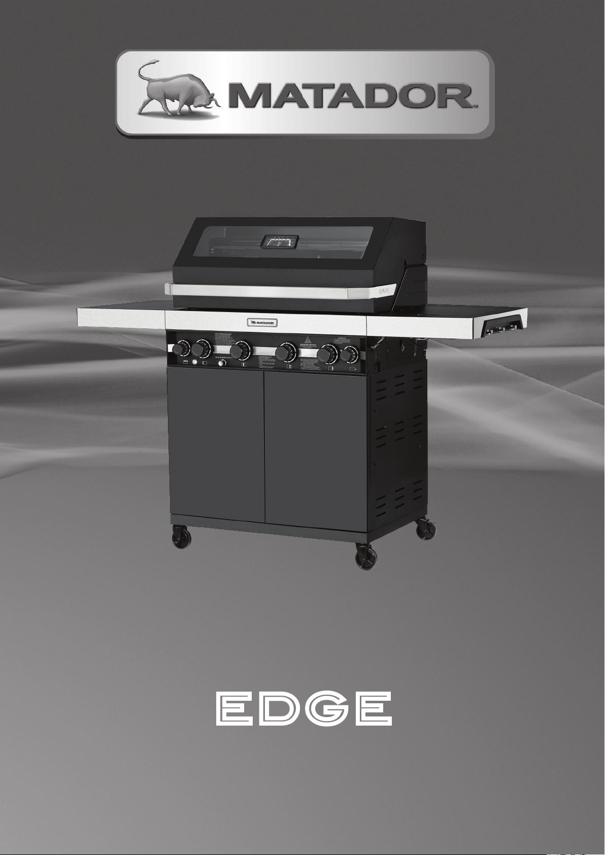
3 BURNER, 4 BURNER AND
Before using the BBQ,
remove any packaging
material within and
around the BBQ
supplied for protection
during transit.
edge
6 BURNER BBQ’S
GB0100, GB0101 & GB0102
Retain manual for future reference.
Page 2
Contents
Features & Benefits 3
Safety Information 4
Do’s & Don’ts 6
Gas Cylinders 7
Positioning the BBQ 8
Gas Leak Test 10
Using your Barbecue 11
Care and Maintenance 13
Natural Gas Conversion 16
Exploded product diagram 17
Part List 20
Hardware List 21
Assembly instructions 22
Troubleshooting 47
Technical Information 48
Spare Parts List 50
Warranty 52
CONTACT INFORMATION
For spare parts, order from your nearest
Bunnings Warehouse. For service and
warranty queries, please contact
Mayo Hardware at
[email protected]
or call;
1300 360 211 (AUS)
09 415 6240 (NZ)
www.matadorbbqs.com.au
BARBECUE DIMENSIONS
EDGE 3 BNR EDGE 4 BNR EDGE 6 BNR
GB0100 GB0101 GB0102
Length 1517 mm 1633 mm 1840 mm
Width 633 mm 663 mm 663 mm
Height 1237 mm 1237 mm 1237 mm
Page 3
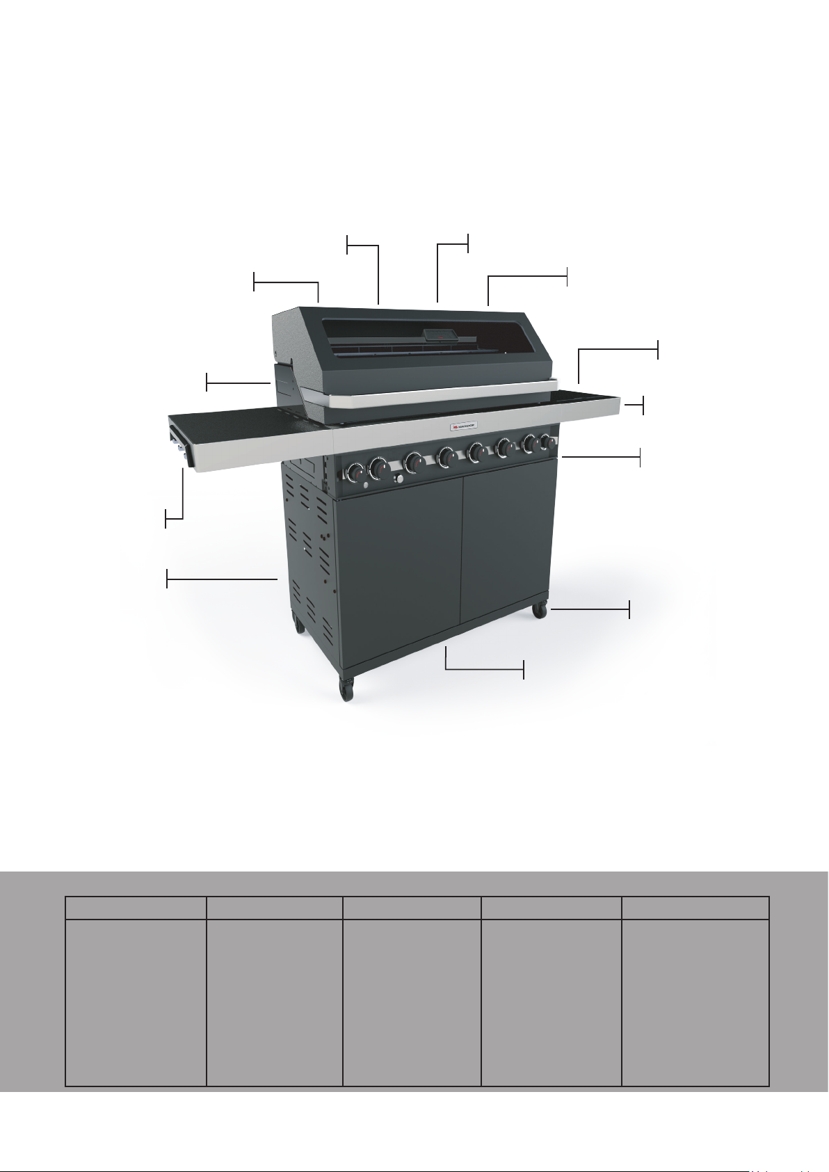
Heat level LED
indicating knobs
High power
side burner
Robust metal
castor wheels
6 Tool hooks &
bottle opener
Large hood
viewing window
Grease management
system
Hood
lights
Dual usb
ports
Rear
burner
Magnetic
door latches
304 Stainless
steel facia panel
4 & 6 BNR ONLY
4 & 6 BNR ONLY
Large Temperature
Gauge
Features & Benets
BARBECUE SPECIFICATIONS
EDGE 3 BNR EDGE 4 BNR EDGE 6 BNR SIDE BURNER REAR BURNER
TOTAL INPUT
ULPG: 45.9 Mj/hr
INJECTOR SIZE:
1.09 mm
PRESSURE: 2.75 kPa
NG: 38.4 Mj/h
INJECTOR SIZE:
1.69 mm
PRESSURE: 1.0 kPa
TOTAL INPUT
ULPG: 61.2 Mjhr
INJECTOR SIZE:
1.09 mm
PRESSURE: 2.75 kPa
NG: 51.2 Mj/h
INJECTOR SIZE:
1.69 mm
PRESSURE: 1.0 kPa
TOTAL INPUT
ULPG: 91.8 Mjhr
INJECTOR SIZE:
1.09 mm
PRESSURE: 2.75 kPa
NG: 76.8 Mj/h
INJECTOR SIZE:
1.69 mm
PRESSURE: 1.0 kPa
TOTAL INPUT
ULPG: 21.1 Mjhr
INJECTOR SIZE:
1.30 mm
PRESSURE: 2.75 kPa
NG: 18 Mj/h
INJECTOR SIZE:
2.08 mm
PRESSURE: 1.0 kPa
TOTAL INPUT
ULPG: 8.7 Mjhr
INJECTOR SIZE:
0.85 mm
PRESSURE: 2.75 kPa
NG: 8 Mj/h
INJECTOR SIZE:
1.35 mm
PRESSURE: 1.0 kPa
MATADOR INSTRUCTION MANUAL
3
Page 4

Safety Information
Read the Instruction manual thoroughly before
assembling or using the barbecue.
This barbecue has been tested and certified in
accordance with Australian Standards
AS 5263.1.7 and is approved for sale and
distribution in Australia and New Zealand.
CAUTION:
FOR OUTDOOR USE ONLY.
• We recommend assembling this barbecue with
another person.
• Estimated assembly time is 2 Hrs.
• Only use this barbecue on a hard, level, noncombustible, stable surface (concrete, ground,
etc.) capable of supporting the weight of the
barbecue.
• Place the barbecue in an area where children
and pets cannot come into contact with it. Close
supervision is necessary when in use.
• Do not use this barbecue for anything other than
its intended purpose.
• Any modifications to this barbecue may be
dangerous. Parts sealed by the manufacturer or
their agent must not be manipulated by the user.
• Never alter or modify the regulator or gas supply
assembly.
• In windy weather, place the barbecue in an
outdoor area that is protected from the wind.
• Use caution when opening the lid. Keep hands,
face and body a safe distance away.
• Use caution during assembly and while
operating your barbecue to avoid scrapes or
cuts from sharp edges of metal parts. Use
caution when reaching into or under the
barbecue.
• Use caution and common sense when operating
your barbecue.
• Do not move the barbecue during cooking.
• Always turn off gas supply after use.
• Use caution when lifting or moving the barbecue
to prevent strains and back injuries. Wait for the
barbecue to cool down prior to moving.
• We advise that a fire extinguisher be on hand.
Refer to your local authority to determine proper
size and type of fire extinguisher.
• Failure to adhere to safety warnings and
guidelines in this manual could result in bodily
injury or property damage.
• When operating and handling the barbecue and
fuel, always wear protective clothing.
• Do not attempt to service the barbecue other
than by normal maintenance, as explained in the
sections of this manual.
• Recycle and/or dispose of all packaging
materials thoughtfully. Check with your local
council recycling rules for further information.
• Ensure manual remains in the possession of the
user for further reference.
WARNING: The barbecue
must not be used
indoors
Contact your local Municipality for any building
codes regulating outdoor barbecue installations.
When using in an enclosure, ventilation must be
provided as per the details on pags 8 & 9. Gas
vapours are highly explosive and can cause serious
injury if allowed to accumulate in a confined space
and ignited.
PRODUCT WARNING LABELS
Do not remove the permanent WARNING labels
that are applied to your barbecue to ensure safe
operation.
DATA SPECIFICATION LABEL:
On your barbecue is a silver data label that contains
detailed information about your product. For your
records on this label will find;
• Product Specifications
• Serial Number
• Manufacturing Date
If you need to contact the manufacturer for
information, technical support or to order spare
parts please have this information at hand.
your matador edge barbecue
date of purchase................................................
model number......................................................
serial no................................................................
date of manufacture.........................................
Page 5
Safety Information
SAFETY COMPLIANCE LABEL
While there is a requirement under the regulations
for all gas products to be safe, the Australian and
New Zealand regulatory environment establishes the
limits of fundamental safety.
The safety compliance label confirms that this
barbecue has been certified as compliant and
deemed suitable for importing and operation in
Australia and New Zealand.
COOKING SURFACE
This barbecue has been tested and certified with
the configuration of solid hot plates and grate plates
that it came with. Changing the number of solid hot
plates on this barbecue will void this certification and
cause a safety issue. DO NOT change the barbecue’s
original configuration of cooking surfaces.
IN CASE OF A FIRE
• If the fire is at the barbecue, turn the gas off at the
cylinder.
• Smother the flames with a wet cloth, fire blanket
or extinguish using a fire extinguisher.
• If you cannot safely reach the valve to turn off
because the fire is at the cylinder, contact the fire
brigade immediately.
• Cool the gas cylinder by directing water from the
garden hose to its centre.
• If gas is burning try to not extinguish it, having
the gas burn off is better than letting the pressure
build up and potentially lead to an explosion.
SETTING UP YOUR GREASE
MANAGEMENT
• Remove the grease tray from the BBQ and line it
with aluminum foil. Try to make this as smooth
as possible so you don’t hinder the flow of oil
and grease.
• Line the bottom of the grease cup with fat
absorber.
• Regularly change the foil and fat absorber to
reduce the chance of fat fires occurring.
• Fires and damages resulting from a build up of
fat and grease are NOT covered under warranty.
PREVENTING FAT FIRES
Your barbecue whilst in use collects a large amount
of fat and grease. Make sure that excessive amounts
of grease or food DO NOT build up in the grease slot
under your cooking plates to reduce the risk of fat fires
occurring.
If your barbecue is not maintained regularly this build
up can lead to a potential fire.
Please refer to the ‘Maintaining Your Barbecue’
section in this booklet for further information on how
to clean and reduce the risk of a fire occurring. If you
have any questions please call the Mayo Hardware
support team for further details.
VENTILATION
When locating your barbecue it is important to
ensure there is adequate ventilation for both the
barbecue and cylinder. This is required not only for
proper combustion, but also to prevent gas build up.
Minimum 20mm ventilation and air-intake gaps are to
be left at rear of the barbecue in fixed installations.
IMPORTANT! PLEASE READ
THESE INSTRUCTIONS
CAREFULLY BEFORE USE!
UNIVERSAL LPG GAS ONLY
MATADOR INSTRUCTION MANUAL
5
Page 6

Do’s & Don’ts
DO’S
• Use inspected exchanged gas cylinders and/
or have cylinders filled by an authorised LPG
supplier in your country.
• Perform a gas leak check on all gas line
connections prior to lighting the barbecue.
• This appliance is designed and approved for use
with LPG / Propane Gas and Natural Gas when
converted by an approved gas fitter using the
available natural gas conversion kit.
LPG Cylinder sizes;
Type 1 - 4 Kg/ 3.2 Kg Fill Capacity 350mm Height
x 240mm Diameter.
Type 2 : 9 Kg / 8.5 Kg Fill Capacity 480mm
Height x 310mm Diameter.
(Cylinder and gas sold separately) Install every
component of the barbecue so it functions
correcly and avoids the risk of injury.
• Before cooking preheat the barbecue for 3 - 5
minutes.
• Always use proper barbecue tools and
accessories when cooking and serving from
your barbecue.
• Take note of your burner temperature when
cooking to achieve the desired result.
• If your barbecue will not light immediately, turn
the knob to off and wait 1 min before trying to
light again.
• Always let you barbecue cool down before
attempting to clean any of the components.
• To remove any grease deposits after cooking,
turn the knob to HI and allow it to burn for 5 min.
This will burn off any build up that has occurred
during your cook.
• Turn off your gas cylinder at the valve after
every cook.
• Regularly clean and maintain your barbecue to
reduce the chance of fire.
• Check your hose and fittings to ensure they are
not cracked or deteriorated to a point that they
need replacing.
DON’TS
• DO NOT install the barbecue closer than 1
meter on the sides or 1 meter in the back to
any combustible surface or less than 1 metre
beneath any overhead combustible construction.
• DO NOT ignite your barbecue with the hood
closed
• DO NOT attempt any adjustment or modification
of the preset regulator.
• DO NOT let LPG cylinder rest on its side. It must
always remain upright.
• DO NOT store gas cylinder indoors, or in any
enclosed area.
• DO NOT obstruct any of the ventilation points of
this barbecue or the cylinder.
• DO NOT operate this barbecue without an
approved gas regulator.
• DO NOT turn on burner knob until a lit match
is in place next to the burner ready for ignition.
(Manual ignition only).
• DO NOT wear long loose flowing clothing
around the barbecue. Long flowing hair is also
easily ignited, especially by unexpected flareups.
• DO NOT leave food unattended for long
periods. It is possible for fats to catch fire at low
temperatures.
• DO NOT use corrosive materials to clean your
barbecue parts.
• DO NOT exceed a temperature of 250°C or
480°F when cooking with the hood closed.
• DO NOT obstruct any of the ventilation points of
this barbecue or the cylinder storage.
• DO NOT apply a protective weather cover until
the barbecue has completely cooled down.
• DO NOT replace any of the grill grates on your
barbecue with extra hot plates. Changing them
will void the warranty and safety certification of
this appliance.
• DO NOT turn on side burner before lifting cover
• DO NOT leave children unattended with this
appliance.
• DO NOT SPRAY AEROSOLS IN THE
VICINITY OF THIS APPLIANCE WHILE
IT IS IN OPERATION.
• Only use the regulator and hose assembly
provided with this appliance. Use only genuine
replacement parts. All replacement parts used
must be of the same specification as originally
supplied with this appliance.
• DO NOT USE OR STORE FLAMMABLE
MATERIALS IN OR NEAR THIS
APPLIANCE.
• DO NOT PLACE ARTICLES ON OR
AGAINST THIS APPLIANCE.
• DO NOT MODIFY THIS APPLIANCE.
Page 7
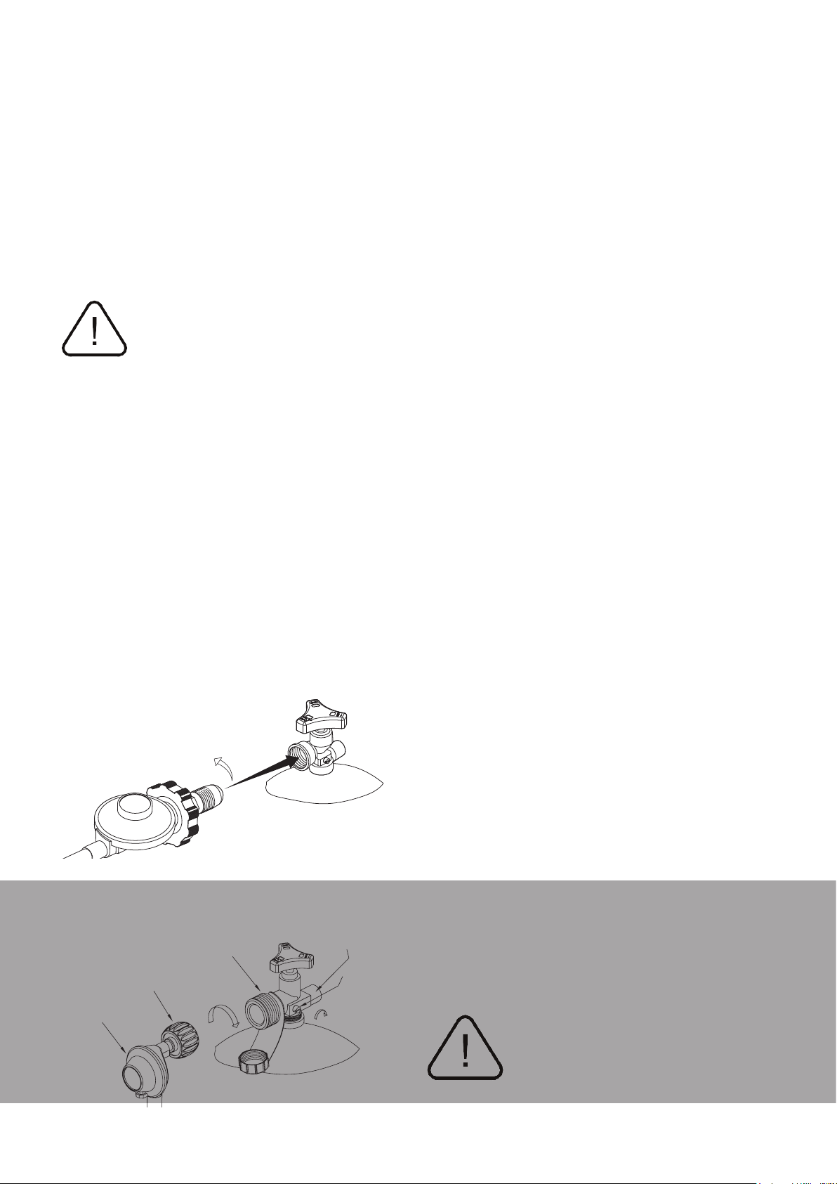
Cylinder Valve
Valve Handle
Regulator
Turn anti-clockwise
to connect
POL Connector
Gas Cylinders
The EDGE BBQ comes ready to be used with
Propane (AUS) / ULPG (NZ) gas cylinders. The
size of cylinder that can be used with this BBQ is
either 4.5kg or 9Kg. Depending on your location
your barbecue will come supplied with the correct
regulator connection to suit your Propane cylinder.
This appliance has the ability to be converted to
Natural Gas, please refer to this section of the
manual for instructions on this process.
how to connect the gas
cylinder to the barbecue
Before connecting the barbecue to the gas cylinder,
please refer to the appliance’s Data Label to verify
you are using the correct gas specification.
The hose and regulator connected to the BBQ have
been leak tested at factory. Do not disassemble or
modify unnecessarily.
1. Check that all control knobs are in the ‘Off’
position.
2. Make sure the cylinder valve is off by turning the
valve knob all the way clockwise.
3. If present, remove the protective cap from
threaded connection on the cylinder.
4. Make connection as described in figure below
depending on the type of regulator connection
that came with your barbecue.
Tighten the regulator connection by hand (no tools) to
ensure it is secure before lighting and operating this
barbecue.
5. Conduct a leak test on all of the gas line
connections on this barbecue (Refer to Gas Leak
Testing Procedure).
how to disconnect the gas
cylinder from the barbecue
When it is time to replace or refill your gas cylinder
please always observe this following procedure:
1. Ensure that all control knobs on the appliance
and the gas cylinder are turned off before
disconnecting the hose and regulator from the
cylinder.
2. DO NOT smoke or use a naked flame near the
appliance or gas cylinder while disconnecting.
3. Remove the gas cylinder from the enclosure
before disconnecting the hose and regulator
from the appliance.
4. Tighten all connections before placing the gas
cylinder back in its enclosure.
gas cylinder storage
• Gas cylinders must be stored outdoors, out of
reach of children and must not be stored in a
building, garage or any other enclosed area. This
excludes from within the barbecue trolley or a well
ventilated outdoor kitchen cabinet.
• This appliance is designed to be used with a gas
cylinder not exceeding 9KG capacity.
Note: POL fitting connectors are left hand threaded
and must be turned anti clockwise to connect.
QCC Connector
PRESSURE
RELIEF VALVE
Turn clockwise
to reseal
BLACK COUPLING NUT
Turn clockwise to connect
REGULATOR
CYLINDER VALVE
BLEED-OFF
VALVE
• The Gas cylinder must be constructed and marked
in accordance with specifications for LP Gas
Cylinders.
• The gas cylinder supply valve must be turned off
when the appliance is not in use.
• The gas cylinder used must incorporate a safety
collar to protect the valve assembly.
• The gas cylinder must always be kept and used in
the upright position.
• DO NOT store a spare LPG cylinder under or near
this appliance.
• NEVER fill a gas cylinder beyond 80 percent full.
• If the information above is not followed exactly, a
fire causing death or serious injury may occur.
ALWAYS STORE GAS
CYLINDER IN A WELL
VENTILATED AREA
MATADOR INSTRUCTION MANUAL
7
Page 8
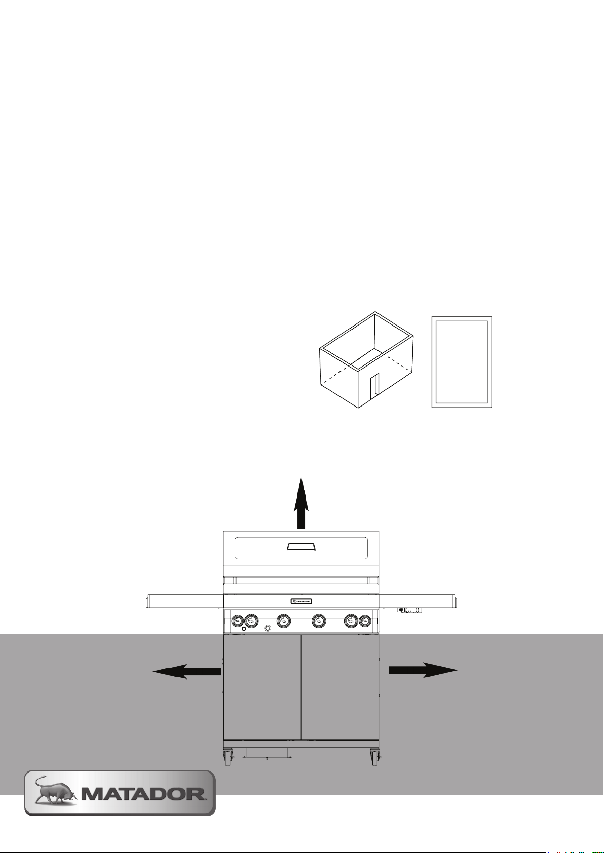
Positioning the BBQ
• This BBQ shall only be used in an above ground
open-air situation with natural ventilation,
without stagnant areas, where gas leakage and
products of combustion are rapidly dispersed by
wind and natural convection.
• When the BBQ is in use, maintain a clearance
of at least 1m between the hot BBQ and any
combustible materials, such as bushes, trees,
wooden fences, buildings, etc.
• Any enclosure in which the appliance is used
shall comply with one of the following:
• An enclosure with walls on all sides, but at least
one permanent opening at ground level and no
overhead cover.
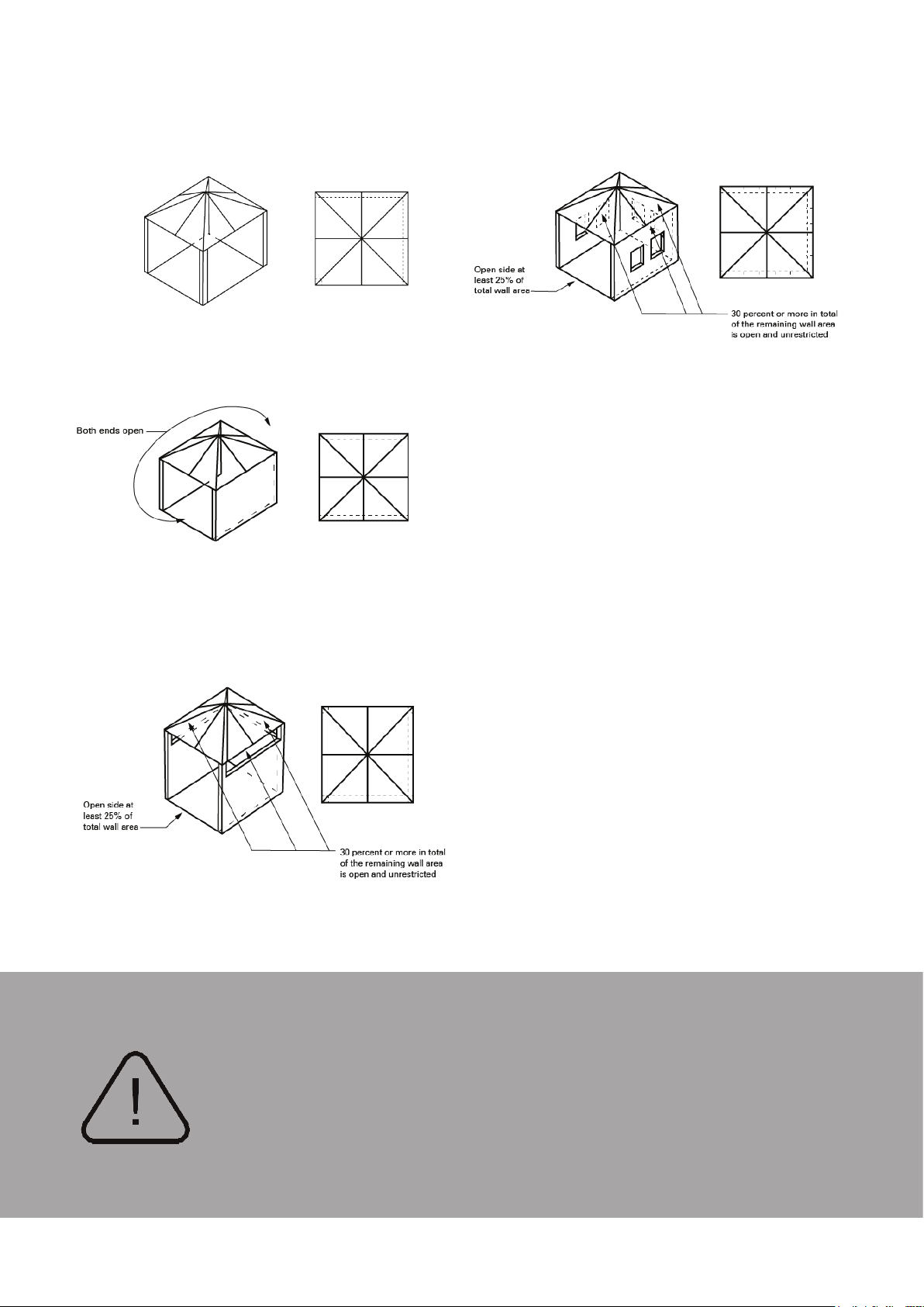
• Within a partial enclosure that includes an
overhead cover and no more than two walls.
• Within a partial enclosure that includes an
overhead cover and more than two walls, the
following shall apply:
• At least 25% of the total wall area is
completely open; and
• At least 30% of the remaining wall area is
open and unrestricted.
• In case of balconies, at least 20% of the total of
the side, back and front wall areas shall be and
remain open and unrestricted.
• The BBQ must not be installed under or on any
combustible material. Minimum clearance from
any combustible materials on ALL sides of the
BBQ is 1000mm and 1000mm overhead.
• BBQ MUST BE ASSEMBLED IN ACCORDANCE
WITH THE MANUFACTURER’S INSTALLATION
INSTRUCTIONS.
• The following figures are diagrammatic
representations of outdoor areas described.
Rectangular areas have been used in these
figures – the same principle applies to any other
shaped area.
1.
An enclosure with walls on all sides, but at
least one permanent opening at ground level
and no overhead cover.
1000mm
1000 mm
1000mm
Page 9
Positioning the BBQ
2.
3.
Within a partial enclosure that includes
an overhead cover and no more than two
walls (See example 2 & 3).
4.
5.
Within a partial enclosure that includes an overhead
cover and more than two walls, the following will
apply:
(i) at least 25% of the total wall area is completely
open, and
(ii) at least 30% of the remaining wall area is open
and unrestricted (see Example 4 & 5).
(iii) In the case of balconies, at least 20% of the total
wall area shall be and remain open and unrestricted.
Power Connection
Your EDGE barbecue needs to be connected to an
outdoor power outlet to function. When positioning
your barbecue you will need to consider this. If you
already have a weatherproof outdoor power outlet
within reach of your barbecue, please plug in the
connected power lead to this point.
If the power outlet location is too far away from the
barbecue, you must use an outdoor rated extension
lead to connect to the power outlet.
For situations where there is no outdoor power outlet
is installed, you will need to ask a licensed electrician
to install an outlet in a suitable position for use with
your barbecue.
BARBECUES MUST BE INSTALLED
IN ACCORDANCE WITH THE
MANUFACTURER’S INSTALLATION
INSTRUCTIONS, LOCAL GAS
FITTING REGULATIONS, MUNICIPAL
BUILDING CODES AND THE GAS
INSTALLATION CODE AS/NZS 5601
MATADOR INSTRUCTION MANUAL
9
Page 10
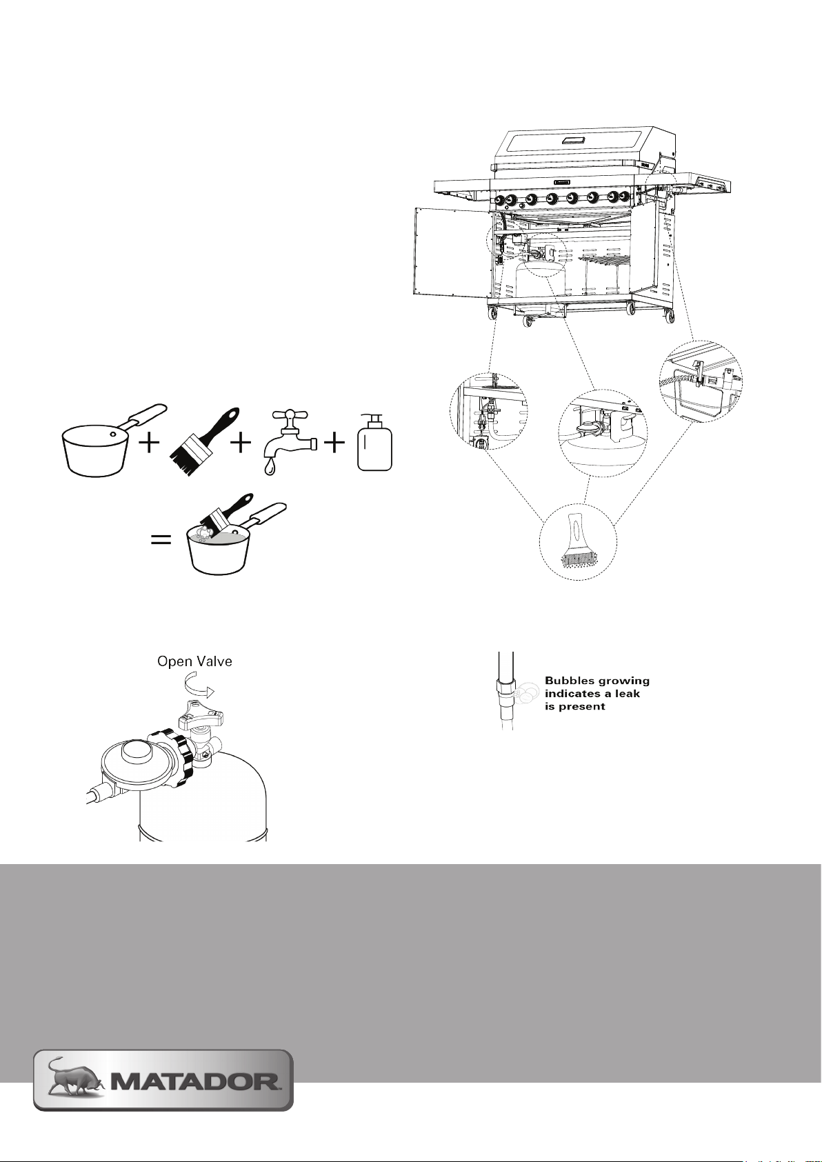
Gas Leak Test
The gas connections on your barbecue were leak
tested at the factory before shipment, however a
complete leak test must be done during assembly.
This leak test must also be conducted every time
you connect the regulator to the gas cylinder for safe
operation.
NOTE:
• Prior to starting this test please ensure the
burner knobs and gas cylinder are both OFF.
• NEVER perform a leak test with an naked flame
Step 1
Make a soap solution with one part water and one
part liquid detergent.
Step 2
Turn on the gas cylinder (Ensuring all the burner
knobs are still in the OFF position).
Step 3
Apply the soap solution to all the gas connections
using a soft bristle brush or spray bottle.
If you smell gas and/or soap bubbles start to appear
from a gas connection it is a sign that a leak is
present.
If there is a leak, turn off your gas supply and tighten
the connection. Repeat the test to ensure that the
leak is fixed.
WARNING
If after repeating the test with tightened connections
a leak is still present, DO NOT use the barbecue
and contact Mayo Hardware Support to assist in
replacing any faulty components.
If you find that the leak is coming from anywhere on
the actual cylinder, take the cylinder outdoors away
from any sources of ignition. Contact the cylinder
exchange provider, or local gas authority, for safe
disposal.
Page 11
Using Your Barbecue
Ground Protection
We recommend placing a grill or bbq mat underneath
your trolley barbecue. This will help to prevent any
accidental damage to the ground surface whilst
cooking.
Lighting your barbecue
1. AUTO IGNITION
Before lighting this barbecue you MUST have
completed the leak test procedure and also read this
manual thoroughly.
Main Burners
Step 1 - Ensure the gas valve on your cylinder is
turned to open.
Step 2 - Lift the hood to the open position.
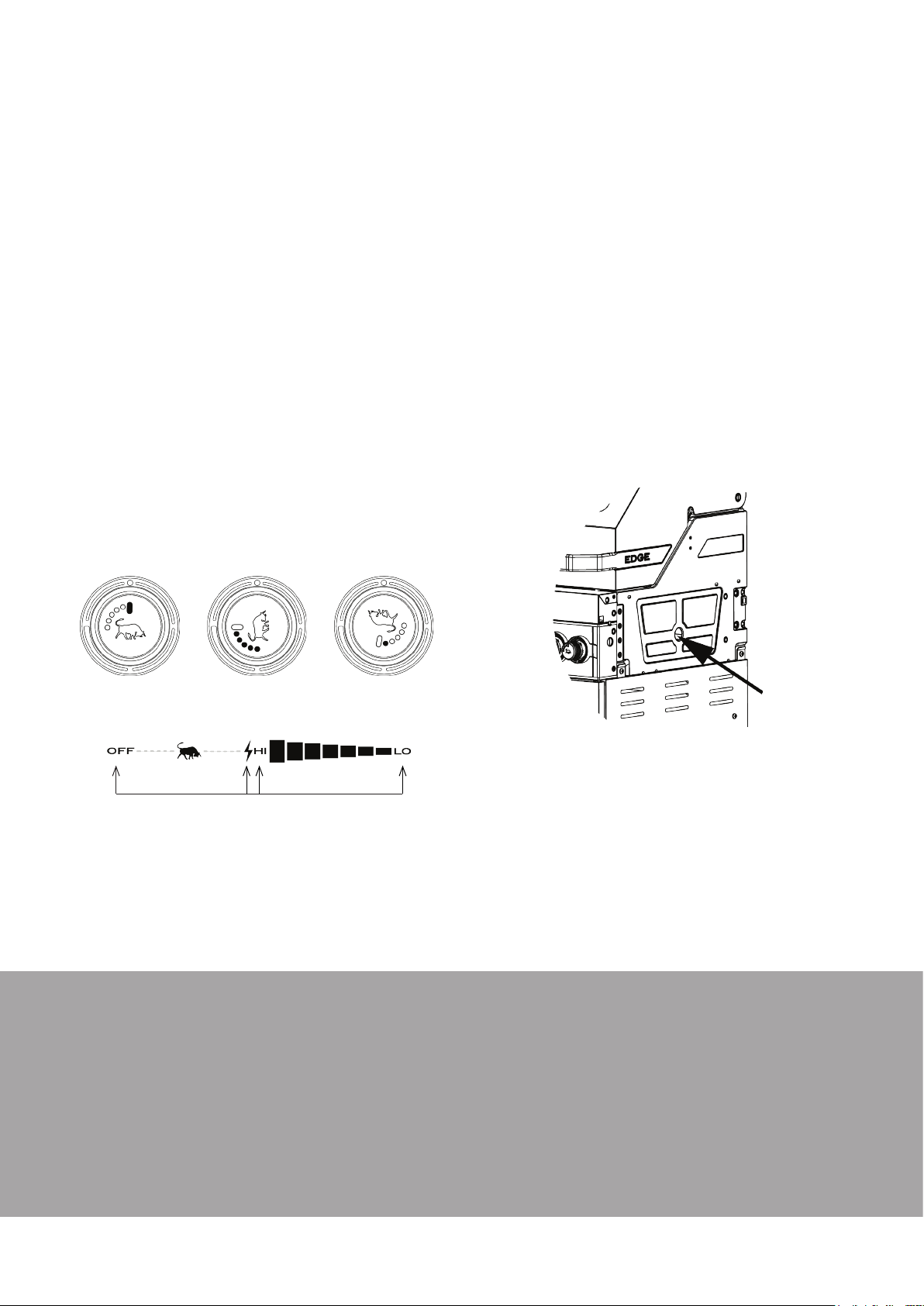
Step 3 - Press and turn the control knob anti-
clockwise to the HI position to trigger the auto-ignition
of the burner. When the burner ignites, release the
knob.
Step 4 - If the burner does not light, return control
knob to the OFF position and wait 2 minutes before
trying again.
Step 3 - Turn the control knob to the HI position
and at the same time press the ‘Rear Burner Ignition
Switch’ to ignite the burner. When the burner
ignites, release the knob.
Step 4 - If the burner does not light, return
control knob to the OFF position and wait 2 minutes
before trying again.
2. MANUAL IGNITION
If you find that you need to manually ignite your
barbecue please follow these instructions carefully.
Main Burners
Step 1 - Ensure the gas valve on your cylinder is
turned to open.
Step 2 - Lift the hood to the open position.
Step 3 - Insert a lit long nozzle gas lighter or long
stemmed match into the lighter hole on the right hand
side of the barbecue (see below).
off
WHITE LED ON
OFF HIGH LOWIGNITE
Side Burner
barbecues only)
Step 1 - Lift the lid on the side burner and retract it
downwards out of the way.
Step 2 - Ensure the gas valve on your cylinder is
turned to open.
Step 3 - Follow the ignition procedure detailed
for the main burners.
Rear Burner (
barbecues only)
NOTE: You need to insert the supplied ‘AAA’ battery
into the ignition switch for it to operate. Refer to
page 13 of this manual for how to insert the battery.
Step 1 - Lift the hood to the open position.
Step 2 - Ensure the gas valve on your cylinder is
turned to open.
HIGH
ALL RED LED ON
(4BNR and 6BNR trolley
4BNR and 6BNR trolley
LOW
ONE RED LED ON
Step 4 - Turn the far right hand control knob to HI
and it will light from the match or gas lighter.
Step 5 - Once lit, turn the next burner to the left
onto HI and light it from the already lit burner. Repeat
this process for all remaining main burners.
Using with the hood down
When cooking with the hood down on your barbecue
do not exceed an internal temperature of 250°C. With
the hood down use only the two outer burners to
control your heat. Temperatures above this can lead to
damage of the appliance and void the warranty.
Pre-heating
To get the best results, we advise pre-heating the
barbecue for 3-5 minutes prior to cooking.
Cooking Surface
Your cooking surfaces are enamel coated and do not
need to be seasoned before use. We do advise to wash
them down with warm soapy water prior to use.
In between cooks we suggest applying a light coating
of cooking oil to protect the surfaces and prevent food
from sticking the next time you cook.
MATADOR INSTRUCTION MANUAL
11
Page 12
Using Your Barbecue
Cooking Utensils
When cooking we recommend using long utensils that
are specifically designed for use on barbecues.
Using your Side Burner
If you purchased a 4 BNR or 6 BNR Trolley BBQ you
will have a side burner. This side burner allows you
greater flexibility in your cooking capabilities.
WARNING: Before lighting your
side burner ensure the lid has
been lifted and retracted down
into its storage position.
• The side burner is a high temperature burner so
take this into consideration when you are cooking.
• The maximum pot/wok diameter size that can be
used on your side burner is 35cm. Larger pots/
woks can lead to damage of your BBQ and void
your warranty.
• The minimum pot base diameter size that can be
used on your side burner is 16.5cm.
• The trivet is designed to work with both flat and
domed woks and pans.
Using your USB ports
Included with the 4 BNR or 6 BNR Trolley barbecues
are twin USB charging ports (charging cable is not
included). The USB ports provide convenience for
charging small appliances such as a mobile phone or
meat thermometer. Appliances that draw larger power
requirements may not function as intended.
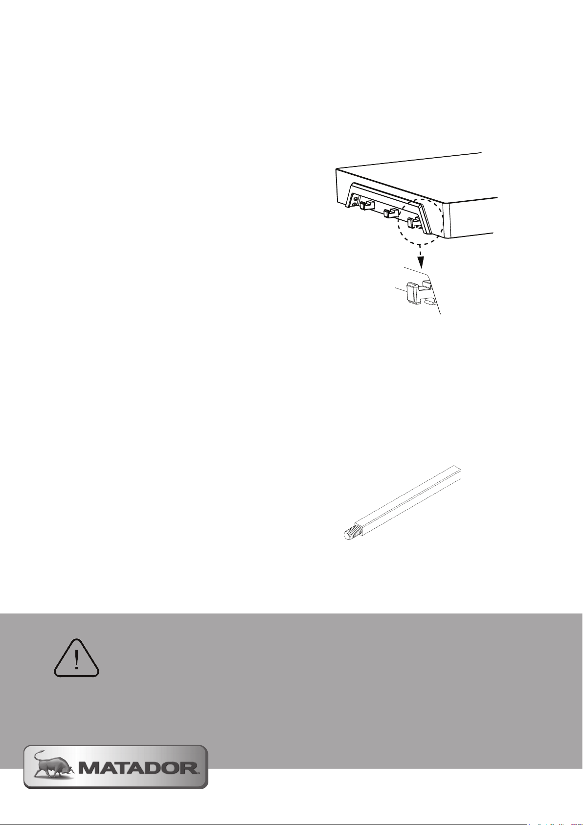
Bottle Opener
For your convenience the EDGE barbecue comes with
an integrated bottle opener. The first hook on the left
hand side of your barbecue is also a bottle opener. See
below for location of this opener.
Installing a Rotisserie
(optional)
Your EDGE barbecue is designed to accept most
major brands of rotisserie accessory products. We
recommend the purchase of the genuine Matador
Rotisserie Kit for use with this barbecue.
If you purchased an EDGE 6 burner barbecue you will
have been supplied with an extension rod (see image
below) that is designed to be used with the Matador
rotisserie kit. It is essential that you use this extension
rod so that your rotisserie kit will function correctly.
• To prevent damage to your charging cables we
suggest feeding your cable through the side vents
in your trolley cabinet. This will allow you to close
the cabinet doors and not damage your cables.
• DO NOT place your appliances on areas of the
BBQ that are hot as this can be a potential fire
hazard and cause . Place your appliance away
from the main BBQ cooking area.
WARNING: DO NOT
place charging
appliance on or
near hot and greasy
surfaces
Please carefully refer to the instructions that came with
your rotisserie kit when installing it onto this barbecue.
When cooking with the rotisserie remember that with
the hood closed the barbecue must not exceed an
internal temperature of greater than 250°C or 480°F.
Page 13
Care & Maintenance
Before Use
Before using your barbecue, ensure that it is clean
from built up grease and residue. Inspect the
barbecue and check that all connections are in order.
After Use
STEP - 1 After you have finished cooking it is
important you turn the burners to HI and burn off
any excess fat and grease residue. Do this for 5
minutes.
STEP - 2 Turn all the control knobs to the OFF
position and turn off the gas supply at the cylinder’s
valve.
STEP - 3 Whilst the barbecue is still warm, and
wearing protective gloves, use a long handled brush
and scraper to remove the remaining oil and food
scraps from the cooking surface.
STEP - 4 Re-coat the grill and hot plate with
cooking oil to provide continued protection.
STEP - 5 Remove the grease cup from the
barbecue and empty the waste and fat absorber.
Place new fat absorber into the cup and re-insert.
Periodical Cleaning
To maintain the performance and high finish of your
barbecue we recommend cleaning it on a regular
basis. To perform this cleaning we recommend the
following;
Burners
• Check your burners for any sort of blockages.
To do this remove the burners and inspect the
burner holes, if any are clogged gently tap the
burner on a hard surface to remove residue.
• Use a wire brush to also clear any of the holes if
required.
Grease Tray
• Remove your grease tray from the barbecue and
remove the foil covering you applied.
• Clean the tray with warm soapy water, dry,
replace the foil and insert back into the
barbecue.
Hose and Regulator
• Safely disconnect the hose and regulator from
the gas cylinder as detailed in this manual.
• Inspect the flexible hose for any signs of wear
and cracking.
• Inspect the rubber O-ring on the regulator end to
ensure no cracks or excessive wear is present.
• If these parts need replacing, only use
recommended manufacturer spare parts.
• On re-attachment of the Hose and Regulator
perform the gas leak test.
Cooking Surfaces
• Remove the hot plate and grill plate from your
barbecue and wash them down with a mild
soapy warm water solution.
• Replace the plates and apply a light coating of
cooking oil for protection.
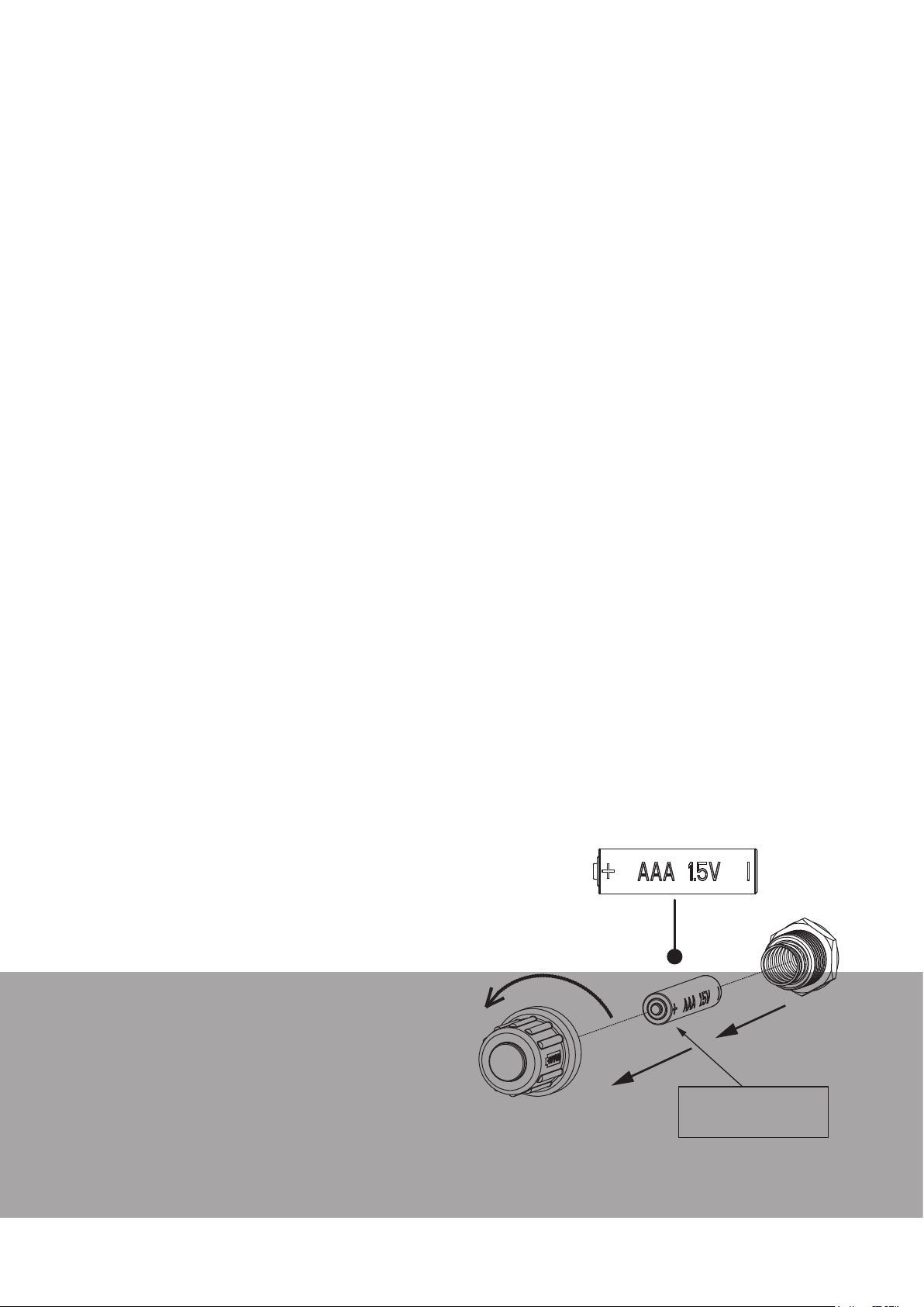
Rear Burner Ignition Battery
• The rear burner ignition switch is powered by
1 x AAA Battery. To replace this battery when
required, unscrew the switch from the front of
the barbecue to access. Re-attach the switch to
secure the battery.
To Remove Burners:
STEP 1 - Using your supplied grate lifting tool, lift
your grill grate from the barbecue. Once removed
you can remove the hot plate.
STEP 2 - Remove the flame tamers that sit
above each of the burners.
STEP 3 - At the rear of the barbecue remove
the screws that secure the burners (2 screws per
burner).
STEP 4 - Lift and swing out the burner from its
resting place over the valve assembly.
STEP 5 - Once cleaned, repeat the above
process in reverse to reassemble the barbecue.
INSERT BATTERY WITH
‘+’ END FACING OUT
FROM THE BBQ.
MATADOR INSTRUCTION MANUAL
13
Page 14

Care & Maintenance
Storage
• To help maintain your barbecue we recommend
using a protective cover (not included). Where
possible store barbecue under a sheltered area.
External Surface Care
Your barbecue has a combination of painted and
stainless steel external surfaces that need to be
maintained.
1. Clean water and wipe
A soft damp cloth and clean warm water should
always be the first choice for mild stains and loose
dirt and soils. A final rinse with clean water and a
dry wipe will complete the process and eliminate the
possibility of water stains.
2. Household cleaners
Household cleaners fall into two categories:
detergent (non-abrasive) and abrasive cleaners.
Abrasive cleaners are more effective but introduce
the possibility of scratching the surface. A neutral
cleaner low in chloride is essential.
The cleaning method generally employed with these
cleaners is to apply them to the powder coated and
stainless surfaces and follow by cloth wiping in the
direction of the grain or polish lines (not across
them).
The cleaned surface should be thoroughly rinsed
with clean water and wiped dry with a soft cloth if
water streaking is a consideration.
Care of the stainless steel on
your barbecue
Your barbecue features stainless steel components.
All stainless steel grades require a level of care and
protection to retain their appearance.
Stainless steels are not immune to corrosion and
neither are they maintenance-free.
Your barbecue has a brushed finish stainless steel
decorative panel and front handle bar. Brushedfinish stainless steel requires frequent cleaning and
care, to maintain its quality of appearance. Without
adequate care it is realistic to expect that it will show
signs of corrosion in time.
The cleaner stainless steel can be kept while in
storage or during use, the greater the assurance of
optimum corrosion resistance. In order to maintain
the life and appearance of your barbecue please
follow these summary tips on the care of stainless
steel:
• When new or when cleaned and dried, we
recommend you apply a thin coat of cooking
oil to stainless steel surfaces which should then
be polished in. This oil will protect the stainless
steel from corrosive contaminants and assist in
the removal of finger prints and other marks.
• Use clean, soft cloths or sponges to clean your
barbecue.
• DO NOT use carbon steel brushes or steel wool
on this barbecue.
• On polished finishes, rubbing or wiping should
be done in the direction of the polish lines, NOT
across them.
• Care must be taken when cleaning areas
with printed information. Text and important
warnings may be erased with heavy cleaning.
Paint Damage
If your hood, trolley or side shelves have paint
damage this can be repaired using ONLY black
high temperature paint. Sand back the effected
area and then re-touch as required per the paint
manufacturers instructions.
• DO NOT use this paint on any internal surfaces
of your barbecue.
If you have chips on the internal baked enamel
surfaces of your barbecue we recommend placing
cooking oil onto these exposed areas to prevent
damage to the metal surface.
Major Maintenance
We recommend every 2 years to have your
barbecue checked by a authorised gas fitter to
ensure all parts are functioning correctly and there
are no leaks.
Page 15
Care & Maintenance
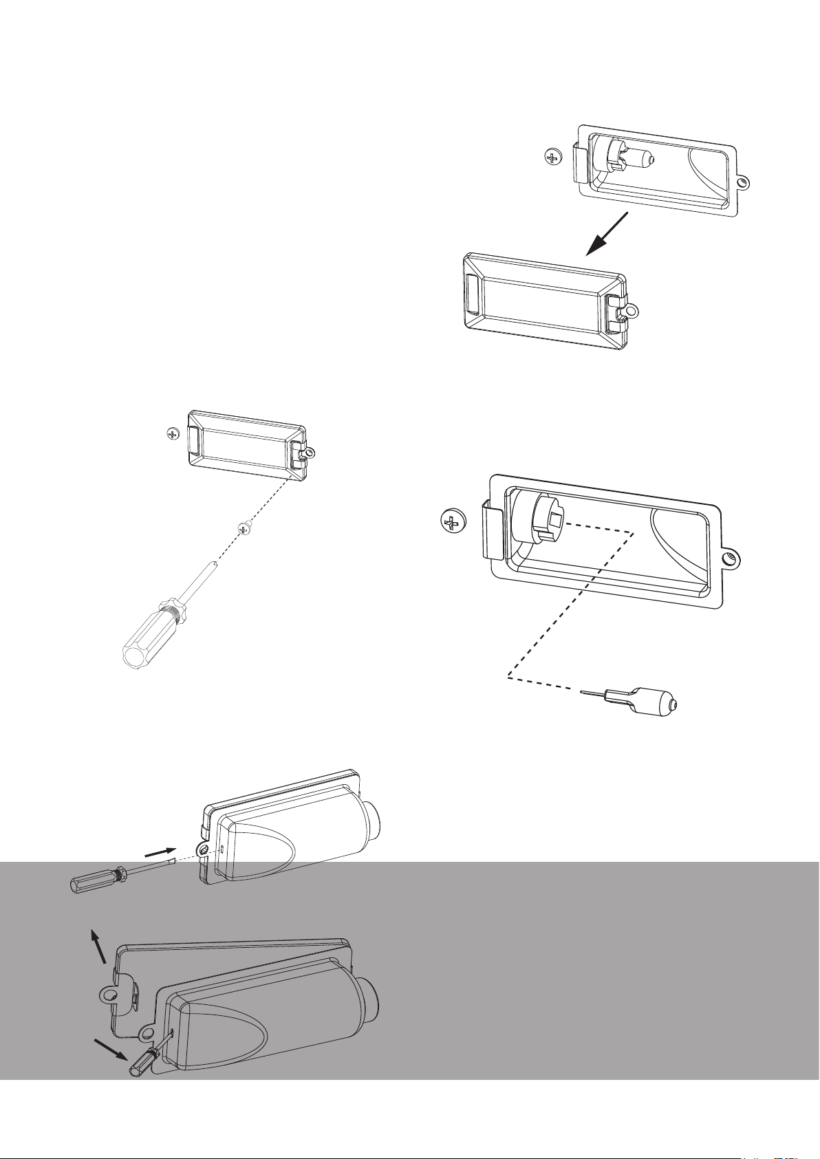
Replacing a Hood Light
Globe
Please follow the following procedure to replace a
hood light globe on your barbecue.
STEP - 1 For safety, turn ‘OFF’ the power to your
barbecue, unplug fromt he outlet and ensure that your
gas cylinder valve is closed.
STEP - 2 Using a Phillips head screwdriver undo
the screw that is holding the lens in place. Remove
the lens and put in a safe place. Whilst this lens is
removed we recommend giving it a good clean in
warm soapy water to improve its performance when
re-installed.
STEP - 3 The globe is connected to the socket
with 2 pins that have been pushed into place.
Gently pull on the globe to remove it from the
socket and carefully dispose.
STEP - 3 Once this screw is removed the light
housing can be removed from inside the BBQ. Using
a flat head screwdriver press the locking detail on the
back of the housing to release the lens of the light.
STEP - 4 Push the new globe (Maximum 10W
Halogen Globe) carefully back into the socket and
make sure it is secure.
STEP - 5 Place the lens back in position and
snap it into the rear housing to lock in place.
STEP - 6 Locate the light housing back into the
mounting hole and use the screw secure in place.
STEP - 7 Turn on the power to the barbecue
and test that the light is now functioning correctly.
MATADOR INSTRUCTION MANUAL
15
Page 16
Natural Gas Conversion
Your EDGE barbecue has been certified that it can
be converted to a natural gas installation from
ULPG. To complete this conversion you must
comply with the following procedure.
STEP - 1 This conversion can ONLY be
completed by a registered Gas Fitter / Plumber.
Please contact one and arrange for a quotation to
convert your barbecue. They will advise on all works
that are required to complete the installation in
accordance with AS/NZS 5601.1.
STEP - 2 Purchase the compatible natural
gas conversion kit from where you purchased
your barbecue or from Mayo Hardware customer
support.
STEP - 3 After your installation has been
completed by the registered authority they LEGALLY
have to issue you with a certificate of compliance for
your records.
STEP - 4 If you do not follow these requirements
in accordance with AS/NZS 5601 you will void your
warranty automatically.
STEP - 5 To complete the installation process
the installer must conduct the leak test on the
barbecue. The barbecue must be checked to ensure
the inlet pressure is correct as per note below;
After the installation has been completed, the
installer must test that operation of the appliance
to ensure it is correctly functioning.
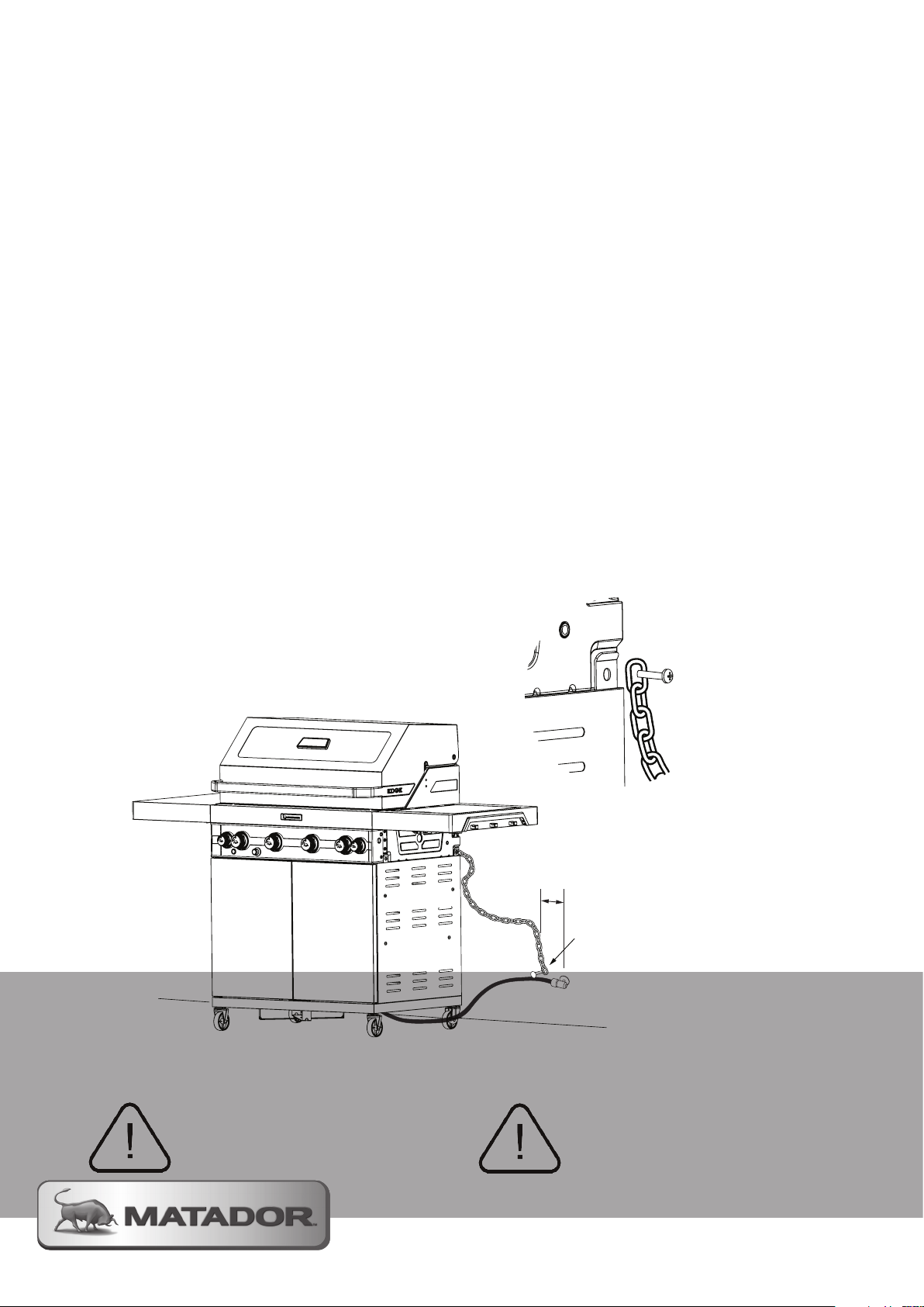
Mobile Restraint Hose
Assembly
When the mobile trolley barbecue is connected to
a fixed gas supply via a flexible hose connection, a
retraining tether of adequate strength shall be fixed
to the appliance and be suitable to be fixed to the
wall within 50mm of each connection point. The
retaining tether must be less than 80% of the gas
hose length.
NOTE:
This gas barbecue is
designed to operate at an
inlet pressure of 1.00 kPa
and must be checked after
installation by turning all
burners on and measuring
at the regulator outlet
test point provided
NOTE: Attach Tether
Chain to the rear of
the barbecue like
shown.
Remove screw from
the BBQ and attach
the tether to the
barbecue using the
new screw supplied
with the conversion
kit.
Do not attempt
to complete this
installation by
yourself!
TETHER TO BE INSTALLED
NOT MORE THAN 50mm
FROM GAS SUPPLY
WALL FASTENERS FOR
THE TETHER ARE NOT
INCLUDED IN YOUR
HARDWARE PACK
GAS SUPPLY
WARNING: ensure
restraining tether
is installed prior
to use!
Page 17
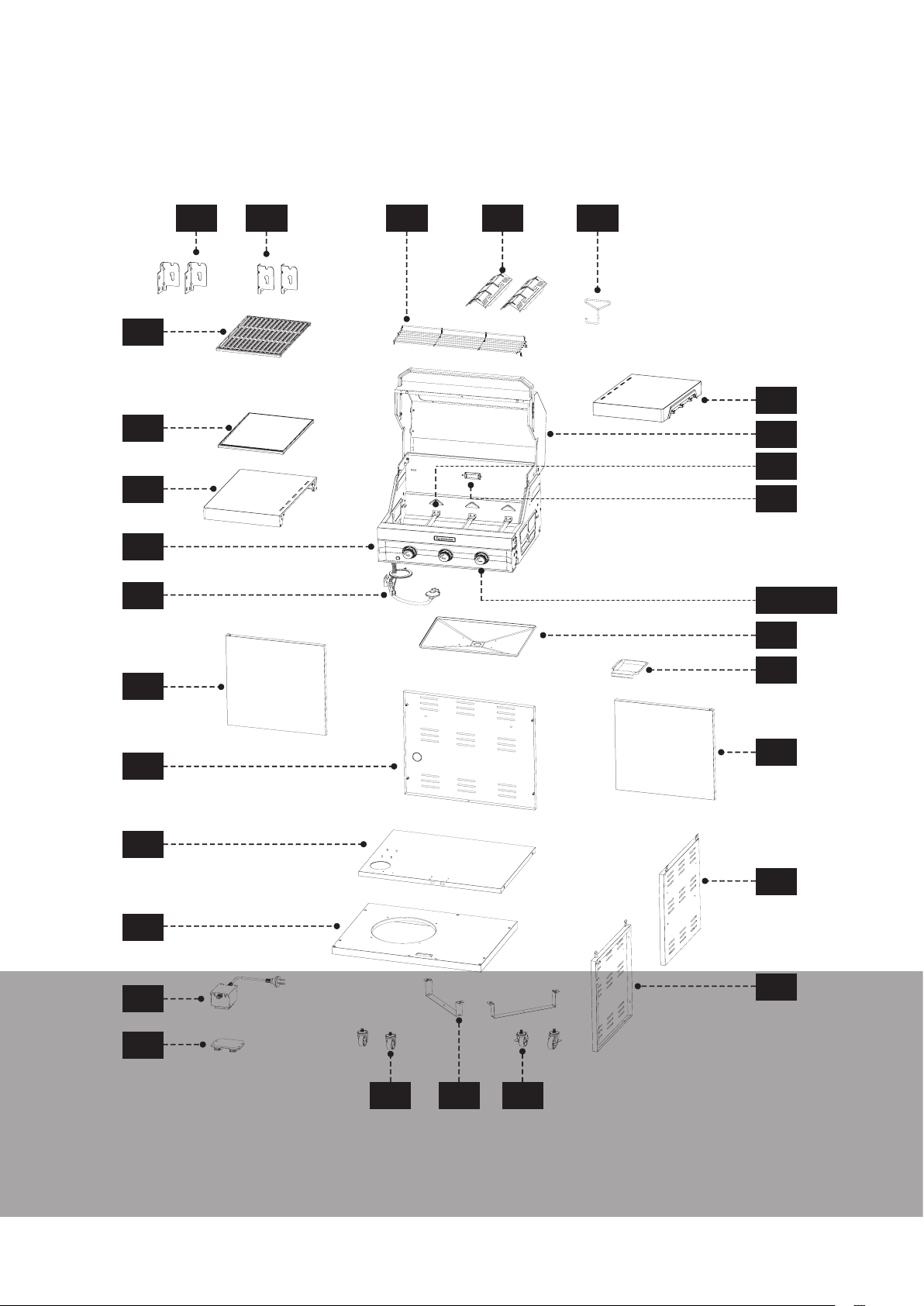
Exploded Parts Diagram
EDGE 3 BURNER BARBECUE
1
2
43
4
5
42 41
363738
31
30
29
28
23/24
22
6
7
8
10
12
13
21
20
19
18
15 16 17
MATADOR INSTRUCTION MANUAL
17
Page 18
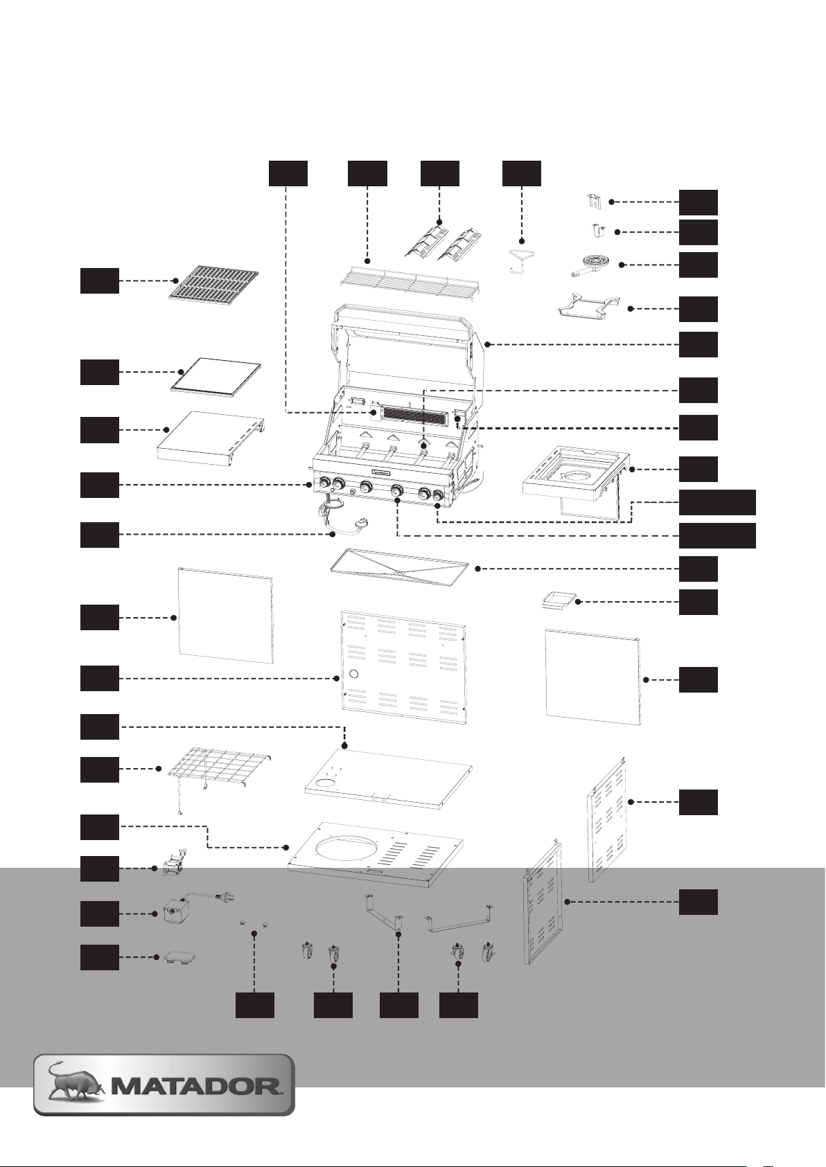
Exploded Parts Diagram
2
3
4
5
6
7
8
9
11
12
13
14 15 16 17
18
19
20
21
22
23/24
25/26
27
28
29
30
32
33
34
35
36373839
1
10
EDGE 4 BURNER BARBECUE
Page 19
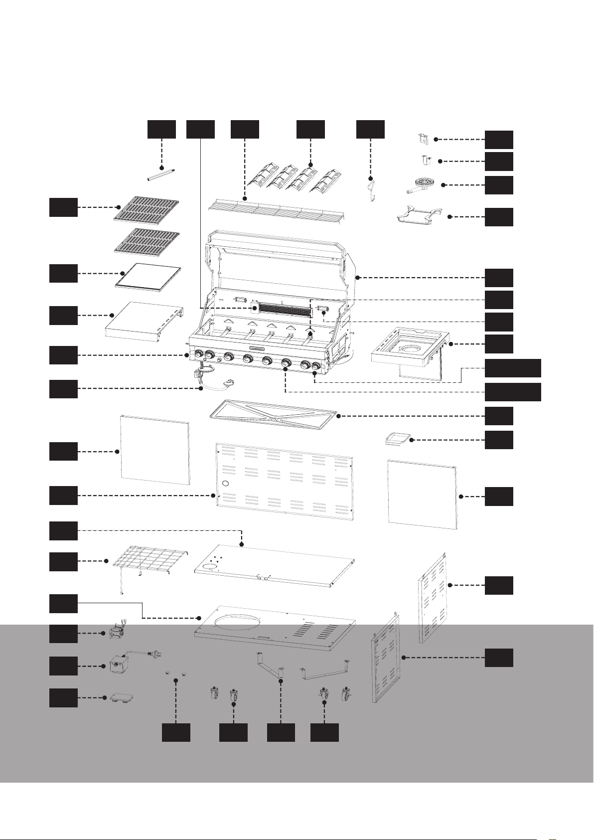
Exploded Parts Diagram
EDGE 6 BURNER BARBECUE
1
2
3
4
5
42
40
36373839
35
34
33
32
30
29
28
27
25/26
23/24
22
6
7
8
9
10
11
12
13
21
20
19
18
14 15 16 17
MATADOR INSTRUCTION MANUAL
19
Page 20
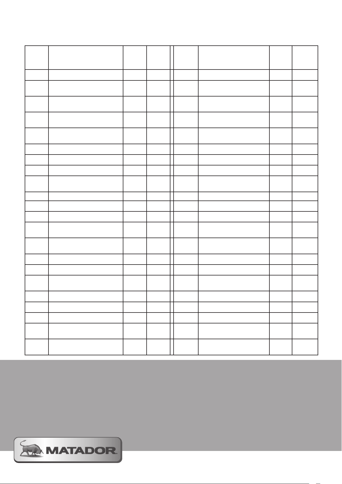
Parts List
Part Name 3
BNR
QTY
1 Cooking Grate 1 1 / 2 23 Large Control Knob 3 4 / 6
2 Solid Hot Plate 1 1 24
3
4 Firebox 1 1 26
5 Hose and Regulator 1 1 27
6 Left Hand Trolley Door 1 1 28 Hood Light 1 2
7 Trolley Rear Panel 2 2 29 Main Burner Assembly 3 4 / 6
8 Trolley Shelf 1 1 30 Hood Assembly 1 1
9
10 Trolley Base Panel 1 1 32 Side Burner Trivet - 1
11 USB Port Assembly - 1 33 Side Burner Assembly - 1
12 Power Adaptor 1 1 34 Side Burner Support - 1
Left Hand Fixed Side
Shelf
Trolley Wire Shelf
Assembly
4 / 6
BNR
QTY
- 1 25 Small Control Knob - 2
0 1 31
Part Name 3
BNR
QTY
Large Control Knob
Base
Small Control Knob
Base
Right Hand Shelf with
Side Burner
Right Hand Folding
Side Shelf
3 4 / 6
- 2
- 1
1 -
4 / 6
BNR
QTY
13 Trolley Door Magnet 1 1 35
14 Rubber Plug 0 2 36
15 Castor 2 2 37 Flame Tamer 2 2 / 4
16 Gas Cylinder Support 2 2 38 Warming Rack 1 1
17 Locking Castor 2 2 39
18 Trolley Left Panel 1 1 40 Rotisserie Extension - 0 / 1
19 Trolley Right Panel 1 1 41 Front Bracket 2 -
20 Right Hand Trolley Door 1 1 42 Rear Bracket 2 -
21 Grease Cup 1 1 43
22 Grease Tray 1 1 44
Side Burner Injector
Bracket
Cooking Grate Lifting
Tool
Infrared Rear Burner
Assembly
Left Hand Folding
Side Shelf
AAA Battery (not
Shown)
- 1
1 1
- 1
1 -
- 1 / 1
For Technical Assistance
and spare parts advice
Call Mayo Hardware on
(AUS) 1300 360 211
(NZ) 09 415 6240
or email us at [email protected]
Page 21
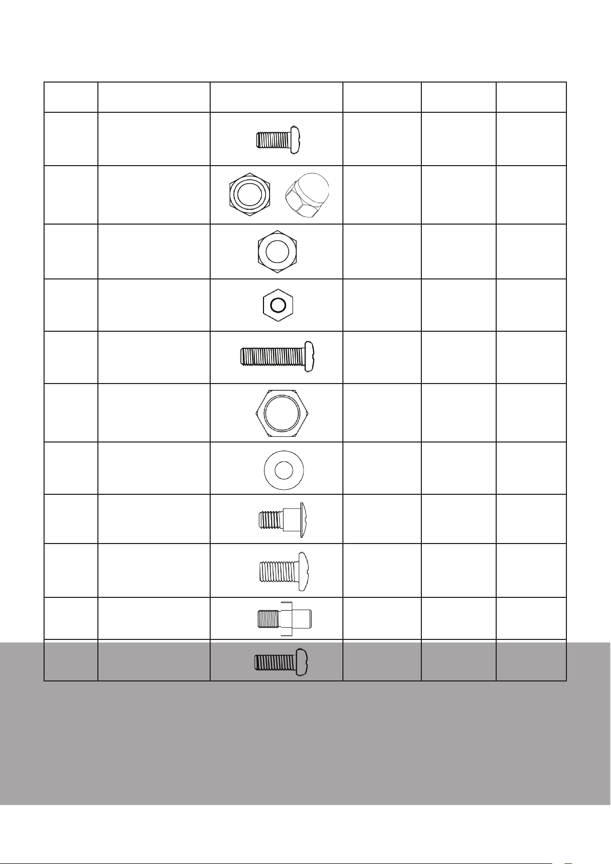
Hardware list
Part Name Hardware Image 3 BNR
QTY
A
B
C
D
E
M4 x 8mm
Pan Head Screw
M6 Hexagon Domed
Cap Nuts
M6 Hex Nut
M4 Hex Nut
M4 x 15mm
Pan Head Screw
- 11 11
2 - -
1 1 1
4 4 4
8 8 8
4 BNR
QTY
6 BNR
QTY
F
G
H
J
L
M
7/16” Collar Nut
6mm Diameter
Flat Washer
M6 Shoulder Screw
M6 x 12mm
Flat Head Screw
M6 Door Pivot
M6 x 16mm
Pan Head Screw
- 1 1
2 2 2
4 - -
36 30 30
2 2 2
4 4 4
MATADOR INSTRUCTION MANUAL
21
Page 22
Assembly Instructions
It is important to read these instructions thoroughly.
If you have any problems, difficulties or concerns
please contact the manufacturer or retailer.
Read all safety warnings and assembly instructions
carefully before assembling or operating your
barbecue. Inspect contents of the box to ensure all
parts are included and undamaged.
We recommend two people for assembly of this
barbecue. The following tools are required for
assembly and are not included:
• Phillips head Screwdriver
• Adjustable Wrench or Socket Set (10mm
Socket)
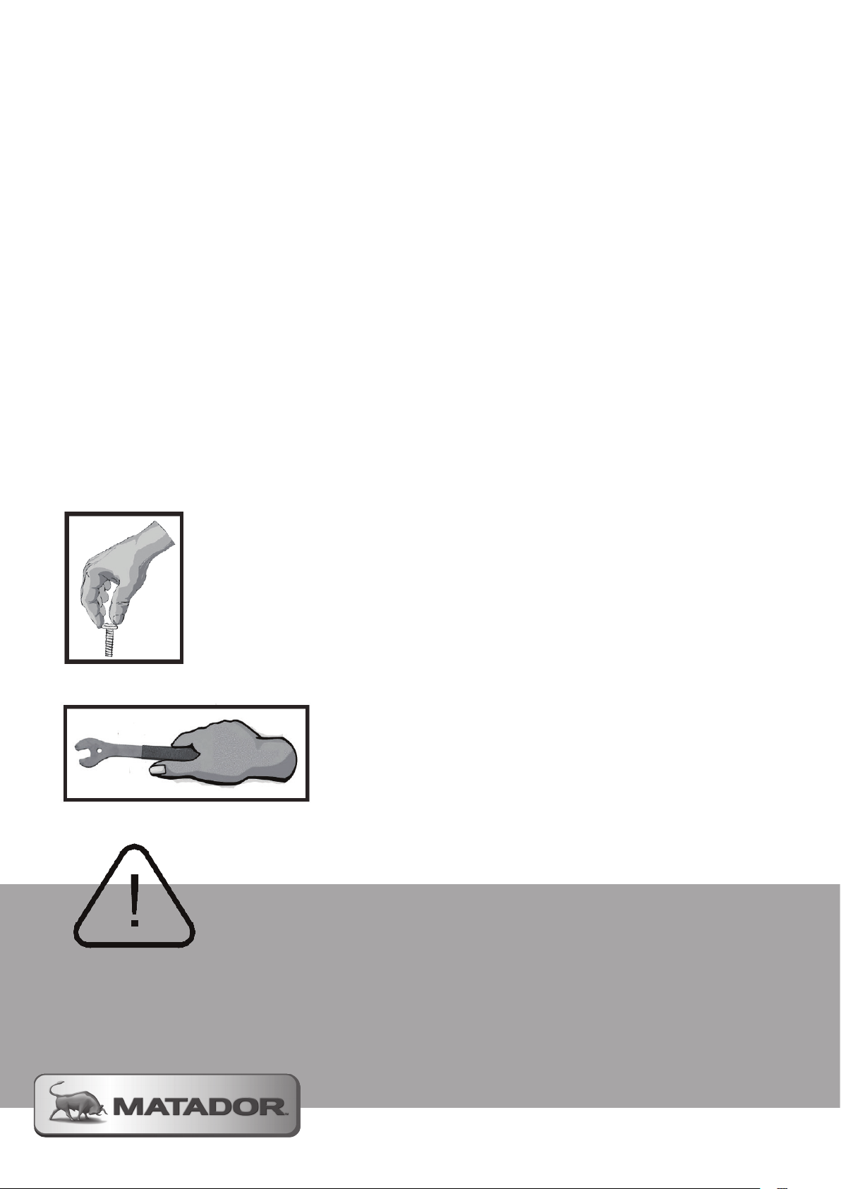
Symbol: The following symbols will be shown in
each procedure for indication of tightening the bolt
and nut if necessary.
Hand Tighten Only at this stage:
Video Instructional Guides
To help you assemble your new Edge Barbecue
videos of the assembly process have been made to
step you through the process.
To access these helpful videos visit:
www.matadorbbqs.com.au
or
www.bunnings.com.au
In addition to the instructional guides you will also
find useful tips, recipes and available barbecue
accessories.
Tighten with Tools at this stage:
Pay Attention at this stage:
Page 23
Assembly Instructions
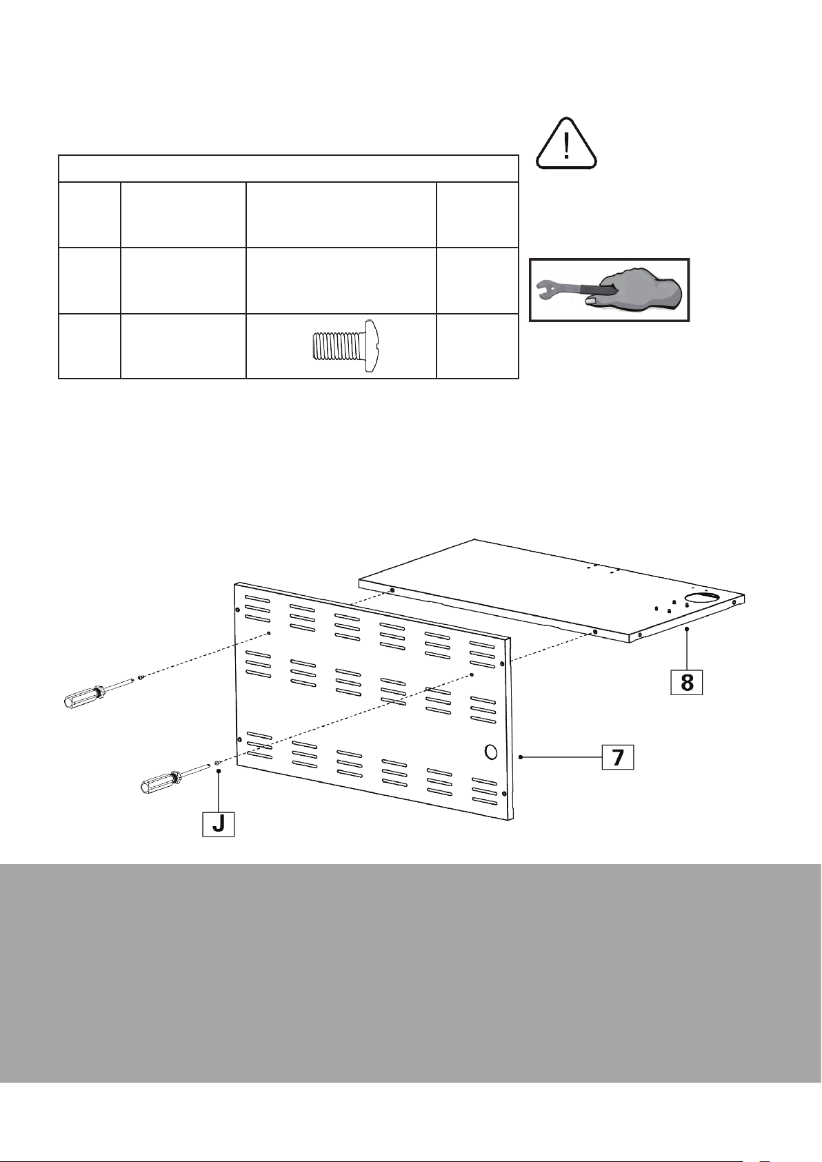
Step 1 - trolley shelf to rear panel
ALL MODELS
Parts / Hardware Needed
NOTE:
7
Trolley Rear
Panel
1
This stage will require a Phillips
head screwdriver
8
J
1.1 Assemble the Trolley Top Panel (8) to the Rear Panel (7) with 2 M6 x 12mm (J) screws.
Pay attention to the orientation of the Trolley Shelf (8) to ensure the folded edges are facing down and that
the large access hole is on the same side as the access hole in the Rear Panel (7).
Trolley Shelf
M6 x 12mm
Flat Head Screw
1
2
MATADOR INSTRUCTION MANUAL
23
Page 24
Assembly Instructions
Step 2 - Assemble Trolley Side Panels
ALL MODELS
Parts / Hardware Needed
NOTE:
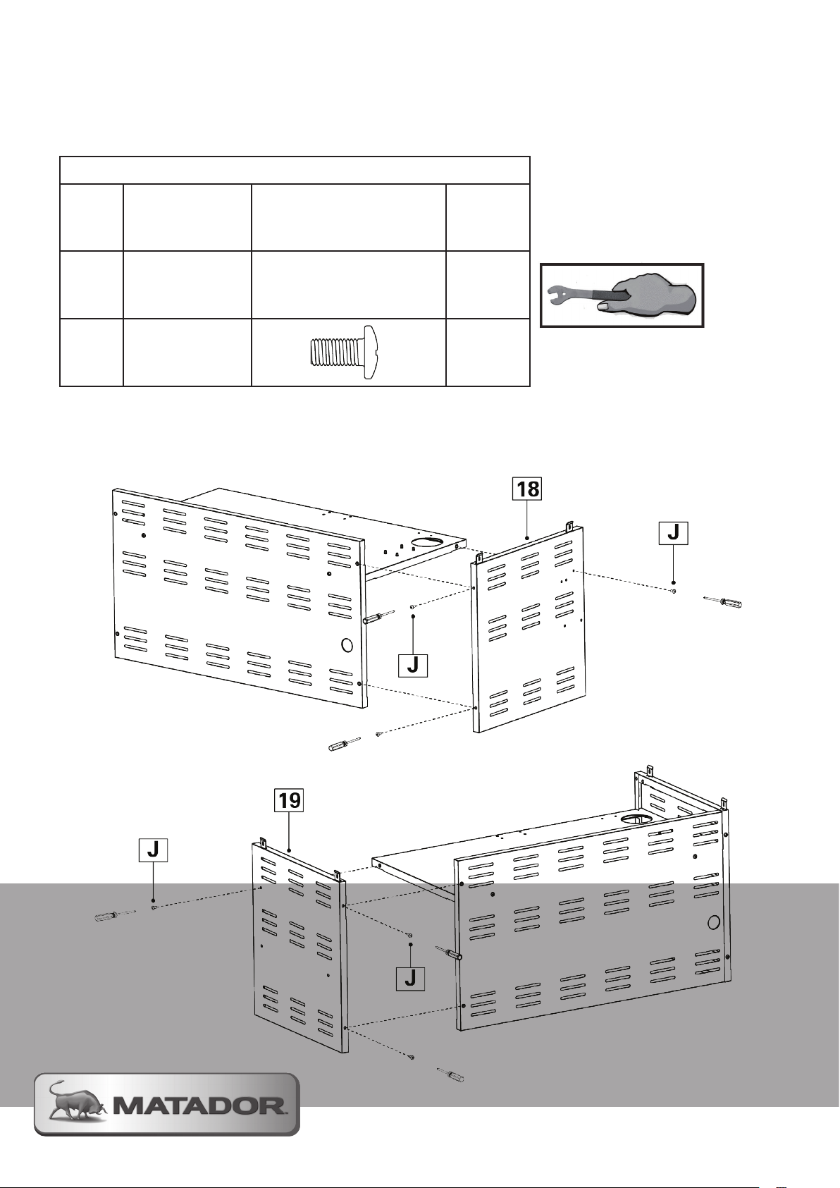
18
Trolley Left
Side Panel
1
This stage will require a Phillips
head screwdriver
19
J
2.1 Screw the Left Hand Side Panel (18) to the Rear Panel and Shelf assembly using 3 M6 x 12mm (J) screws.
2.2 Now assemble the Right Hand Side Panel (19) using the same method
Trolley Right
Side Panel
M6 x 12mm
Flat Head Screw
1
6
Page 25
Assembly Instructions
Step 3 - Assemble the power adaptor
ALL MODELS
Parts / Hardware Needed
NOTE:
12
E
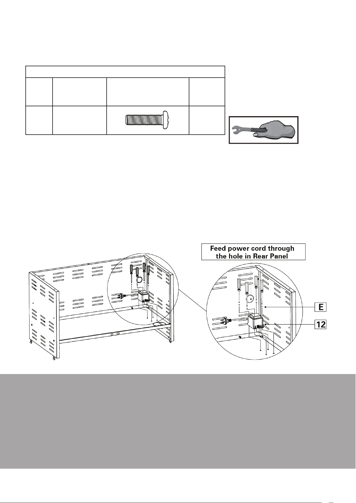
3.1 Carefully turn over the barbecue assembly so you can easily access the underside of the Trolley Shelf (8)
3.2 Align the Power Adaptor’s (12) 4 mounting holes with the 4 mounting points on the Trolley Shelf (8) and
fasten with 4 M4 x 15mm Pan Head Screws (E).
3.3 After securing the Power Adaptor (12) feed the power lead through the access hole in the Trolley Rear
Panel (7)
3.4 Leave the barbecue assembly upside down for now
Power Adaptor
M4 x 15mm
Pan Head Screw
1
4
This stage will require a Phillips head
screwdriver and a 10mm socket (or
adjustable wrench) to tighten the
securing hardware.
MATADOR INSTRUCTION MANUAL
25
Page 26
Assembly Instructions
Step 4 - Attach Trolley Door Pivots
ALL MODELS
Parts / Hardware Needed
NOTE:
10
Trolley Base
Panel
1
This stage will require an
adjustable spanner.
L
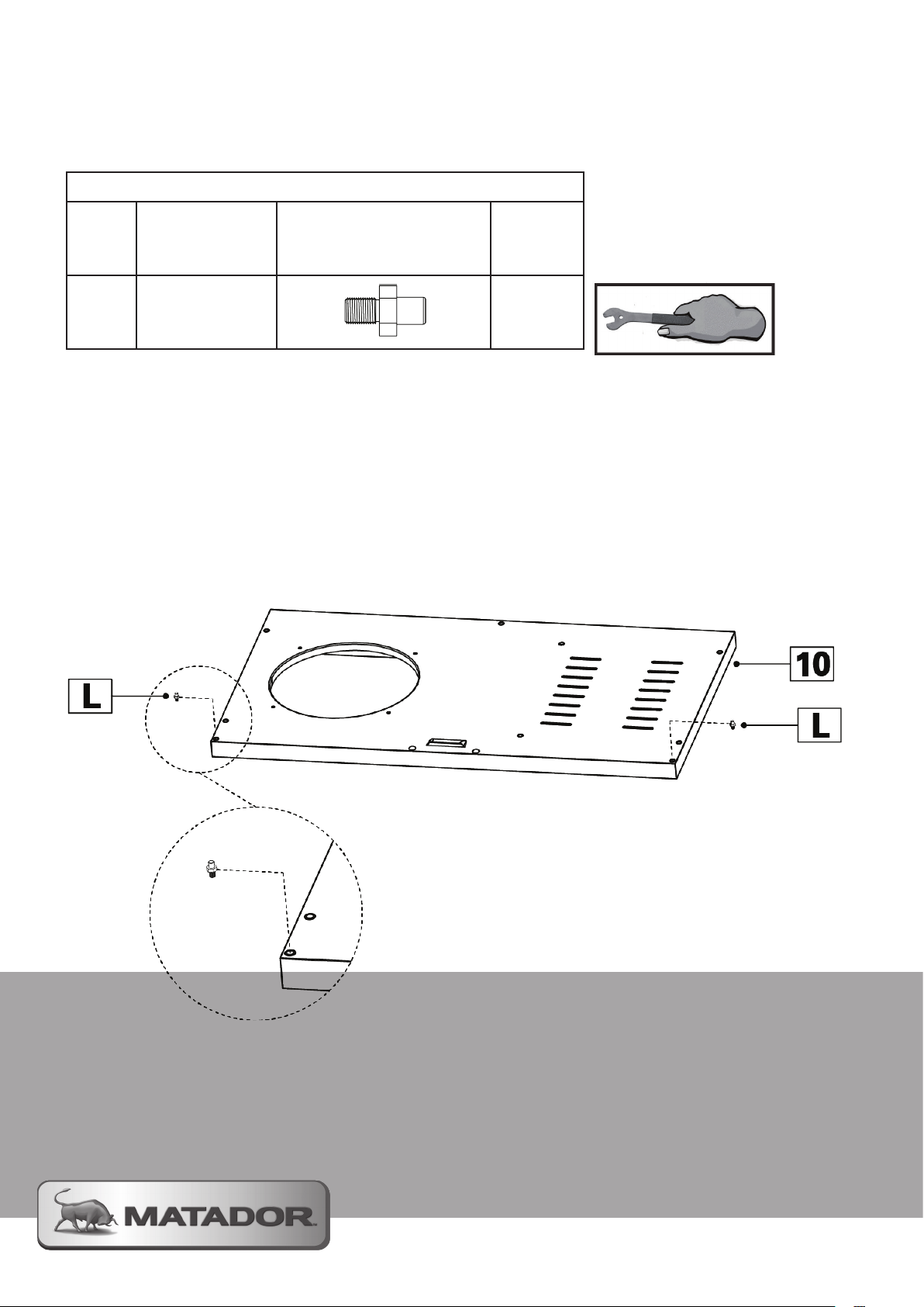
4.1 Screw the 2 M6 Door Pivots (L) into the 2 holes located at the front corners of the Trolley Base Panel (10)
NOTE: Secure the pivots firmly but do not over tighten them
M6 Door Pivot
2
Page 27
Assembly Instructions
Step 5 - Install Trolley Castors
ALL MODELS
Parts / Hardware Needed
15
17
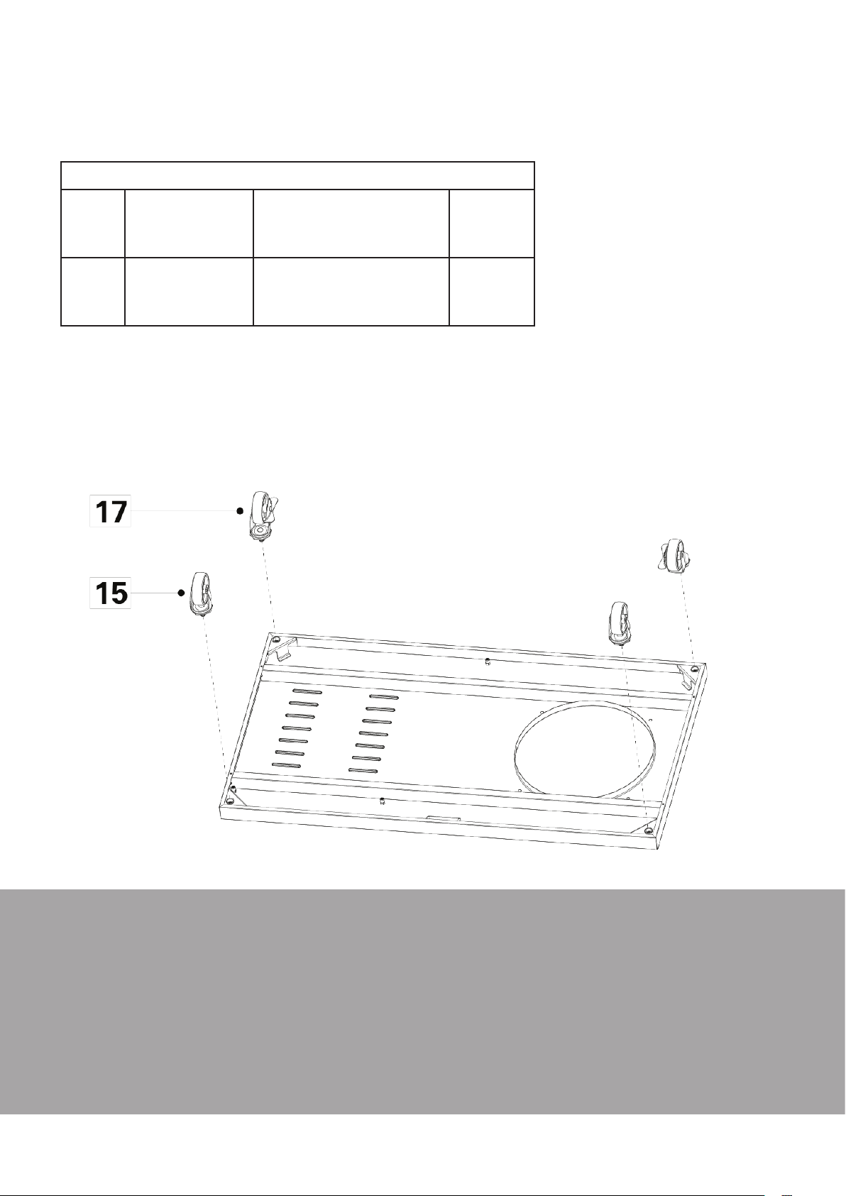
5.1 Turn over the Trolley Base Panel (10) to allow access to the 4 Castor mounting points.
5.2 Attach the 2 non-locking Castors (15) to the front corners of the Trolley Base Panel (10)
5.3 Attach the two remaining Locking Castors (17) to the rear of the Trolley Base Panel (10)
5.4 Turn over the assembly so that it is sitting on its wheels. You may want to lock the rear Castors to help in
assembling further components.
Castor
Locking Castor
2
2
MATADOR INSTRUCTION MANUAL
27
Page 28
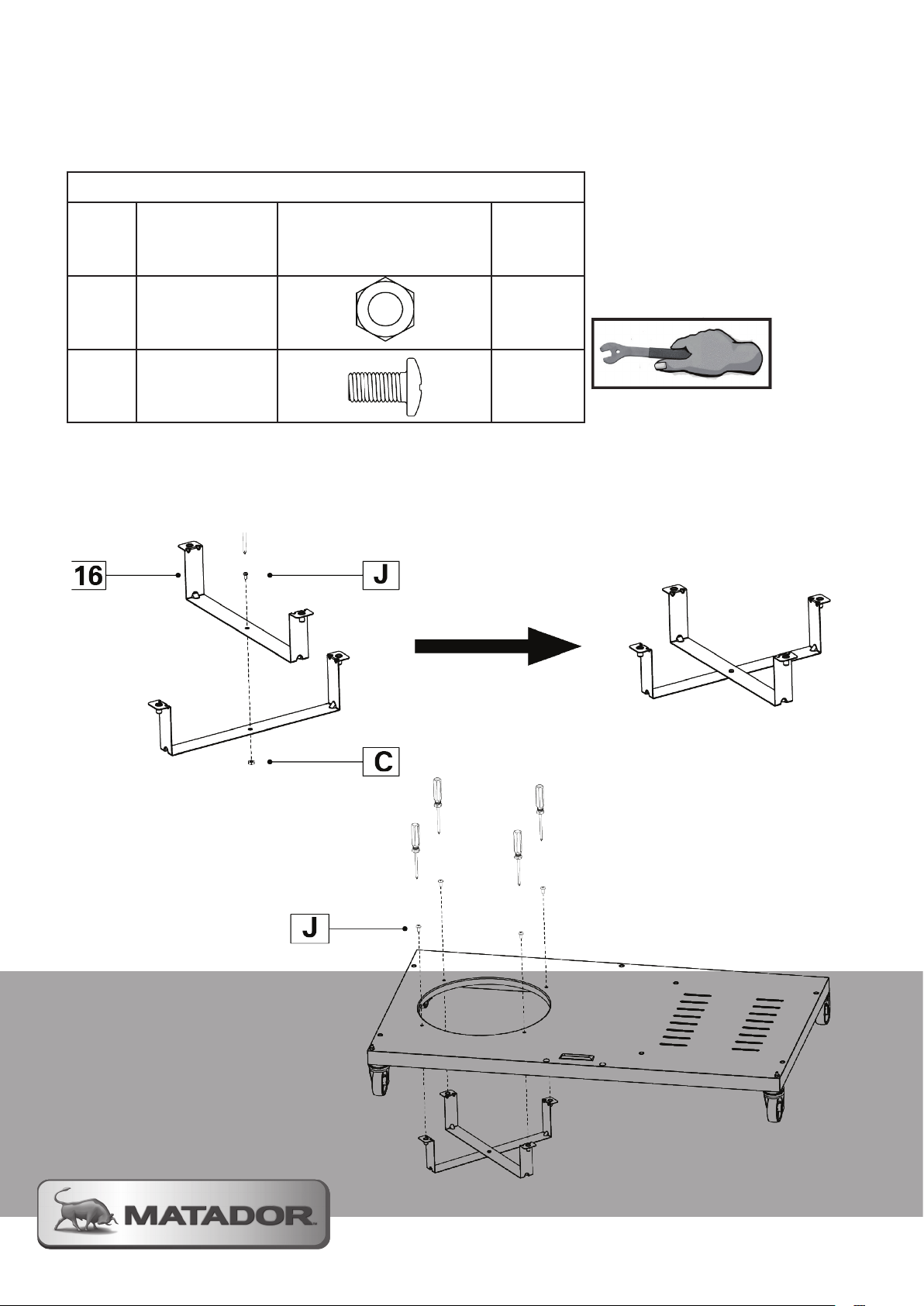
Assembly Instructions
Step 6 - Gas cylinder support
ALL MODELS
Parts / Hardware Needed
NOTE:
16
Gas Cylinder
Support
2
This stage will require an
adjustable spanner or a 10mm
spanner and a Phillips head
screwdriver
C
J
6.1 Using 1 M6 x 12mm Screw (J) and the M6 Hex Nut (C) secure the 2 Gas Cylinder Supports (16) together
so they are at 90 degrees to each other.
6.2 Locate the Gas Cylinder Supports underneath the Trolley Base Panel (10) with the 4 mounting holes
surrounding the cylinder access hole and secure with 4 M6 x 12mm Screws (J)
M6 Hex Nut
M6 x 12mm
Flat Head Screw
1
5
Page 29
Assembly Instructions
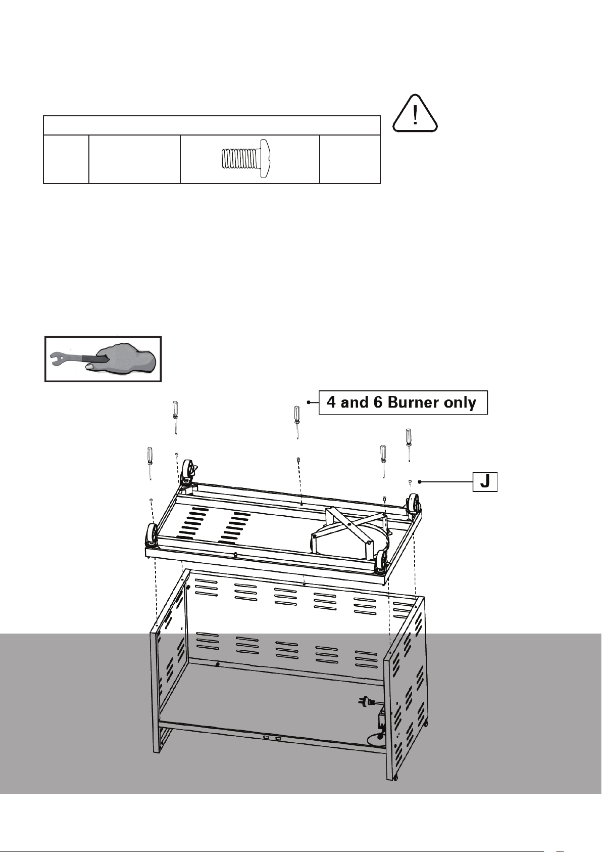
Step 7 - Trolley base assembly
ALL MODELS
Parts / Hardware Needed
NOTE:
J
7.1 Take the base assembly and locate it onto the trolley assembly from Step 3
7.2 Position the base so that all the corresponding mount holes are aligned and then secure using 4 M6 x
12mm Screws (J).
7.3 Carefully lift and turn the trolley assembly over so it is now resting on its castors.
NOTE: We recommend asking for someone to help you lift and turn over the trolley to avoid injury and
damage to the barbecue.
M6 x 12mm
Flat Head Screw
5
3 BNR Trolley assembly will only
have 4 screws at this stage. There
is no central screw required.
This stage will require a Phillips
head screwdriver to tighten the
securing hardware.
MATADOR INSTRUCTION MANUAL
29
Page 30
Assembly Instructions
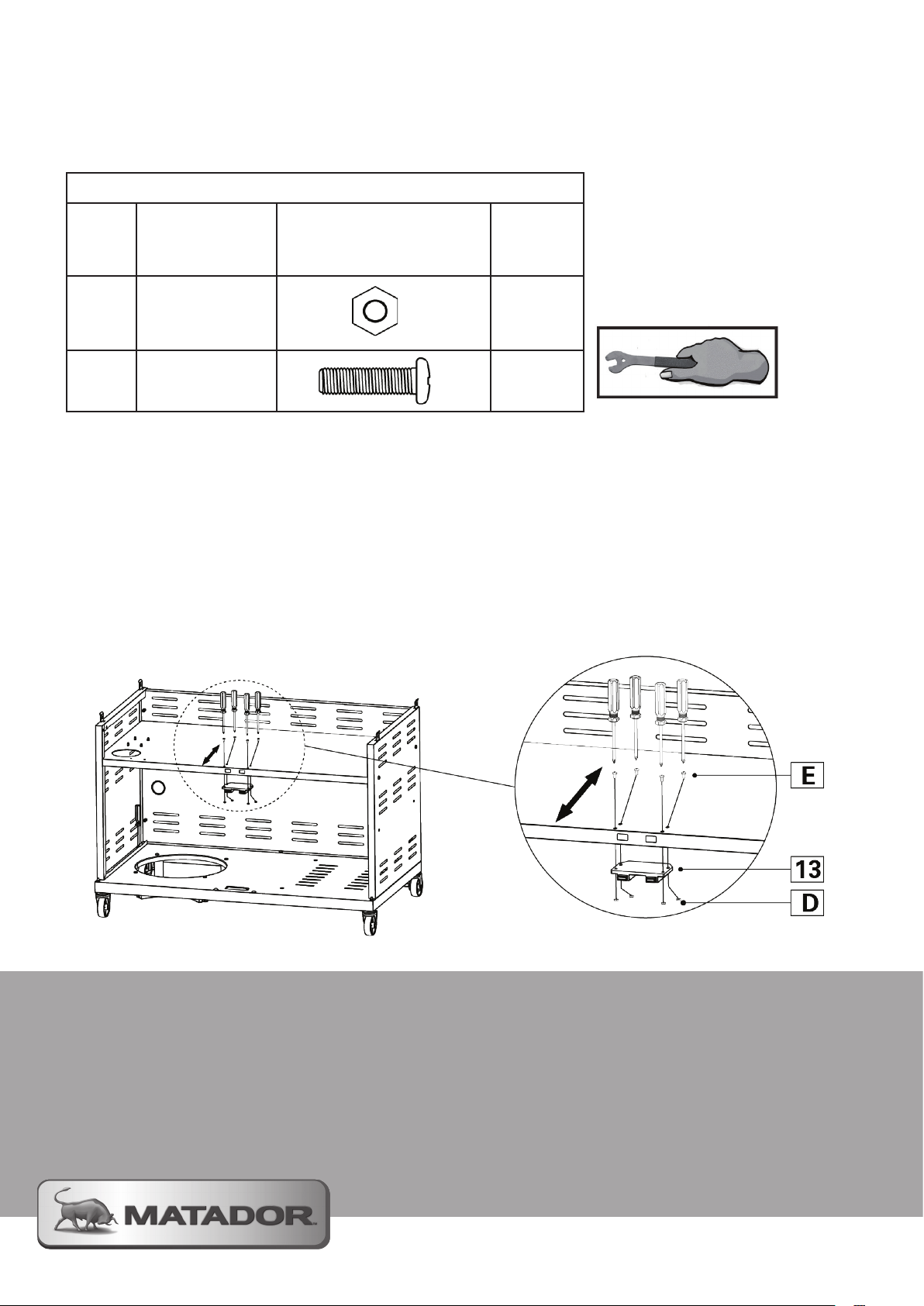
Step 8 - Attach Trolley Door Magnet
ALL MODELS
Parts / Hardware Needed
NOTE:
13
Trolley Door
Magnet
1
This stage will require an
adjustable spanner or a 10mm
spanner and a Phillips head
screwdriver
D
E
8.1 Place the Trolley Door Magnet underneath the Trolley Shelf (8) and feed the magnetic latches through the
two openings on the front face of the shelf.
8.2 Secure the Trolley Door Magnet using 4 M4 x 15mm Screws and M4 Hex Nuts.
NOTE: These magnetic locks can be adjusted to improve their operation if required
M4 Hex Nut
M4 x 15 mm
Pan Head Screw
4
4
Page 31
Assembly Instructions
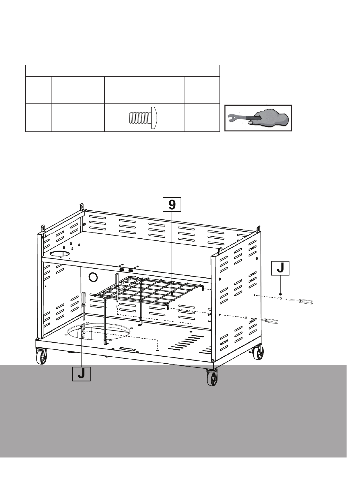
Step 9 - Attach Internal Trolley Shelf
4 BNR AND 6 BNR MODELS ONLY
Parts / Hardware Needed
NOTE:
9
Trolley Wire
Shelf Assembly
1
This stage will require a Phillips
head screwdriver
J
9.1 Unfold the shelf support legs and position the shelf inside the trolley assembly.
9.2 Secure the Trolley Wire Shelf Assembly (9) to the side of the trolley assembly using 2 M6 x 12mm
Screws (J)
9.3 Take 2 more M6 x 12mm Screws (J) and secure the Wire Shelf (9) to the base of the trolley assembly.
M6 x 12mm
Flat Head Screw
4
MATADOR INSTRUCTION MANUAL
31
Page 32
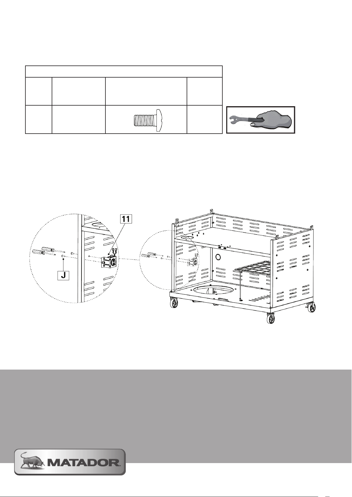
Assembly Instructions
Step 10 - Attach the USB Ports
4 BNR and 6 BNR MODELS ONLY
Parts / Hardware Needed
NOTE:
This stage will require a Phillips
head screwdriver
11
USB Port
Assembly
1
J
10.1 Locate the USB Port Assembly (11) to the left hand side inside the trolley assembly.
10.2 Use 2 M6 x 12mm Screws (J) to secure to the trolley assembly
NOTE: The cables from the USB Ports should be facing the back of the trolley
M6 x 12mm
Pan Head Screws
2
Page 33
Assembly Instructions
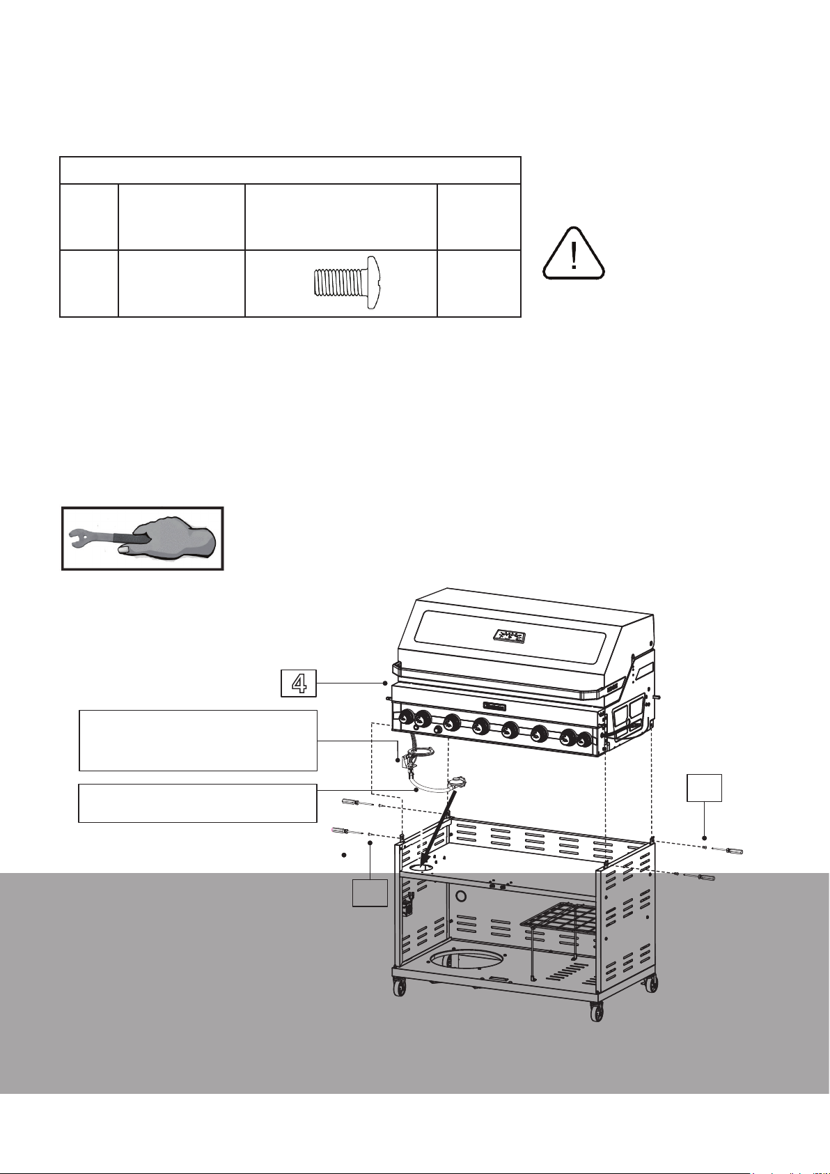
Step 11 - Attach firebox to Trolley Assembly
ALL MODELS
Parts / Hardware Needed
NOTE:
4
Firebox
1
This stage will require a Phillips
head screwdriver
J
11.1 Carefully lower the Firebox (4) onto the Trolley Assembly
11.2 Feed the hose, regulator and bracket assembly through the access hole in the Trolley Top Panel (8). The
round seal ring does not feed through the access hole.
11.3 Use 4 M6 x 12mm Screws (J) to secure the Firebox (4) to the Trolley Assembly.
NOTE: You must get someone to help you lift the Firebox onto the Trolley to avoid injury and damage to the
barbecue.
M6 x 12mm
Pan Head Screws
4
DO NOT lift the Firebox onto the
Trolley Assembly by yourself. This
is to avoid personal injury and
damaging the barbecue.
4
Regulator and light
connection wire
Hose and Regulator
J
GAS INLET SPECIFICATION (for use with ULPG)
3/8” SAE Flare with 5/8-18 UNF Thread
J
MATADOR INSTRUCTION MANUAL
33
Page 34
Assembly Instructions
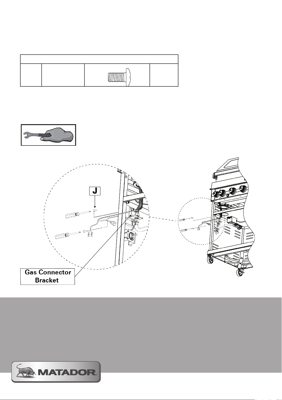
Step 12 - Secure the Gas Connector Bracket
ALL MODELS
Hardware Needed
NOTE:
J
12.1 Locate the Gas Connector Bracket against the inside of the trolley with the 2 mount holes above the
USB Ports.
12.2 Secure the bracket assembly to the inside panel of the trolley with 2 M6 x 12mm Screws (J)
NOTE: The cables from the USB Ports should be facing the back of the trolley
M6 x 12mm
Pan Head Screws
2
This stage will require a Phillips
head screwdriver
Page 35
Assembly Instructions
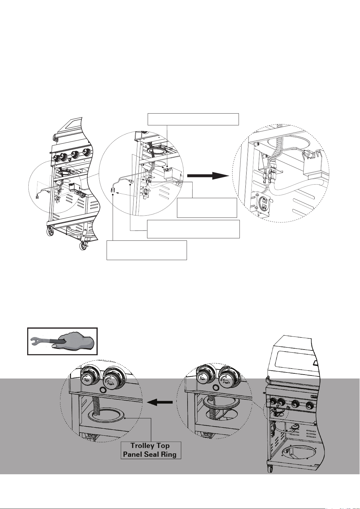
Z - Power Adaptor Input
W - USB Power Cable
from Firebox
Y - Power Adaptor Wire
Terminal from Firebox
X - USB Plugs
from Bracket
Step 13 - Connection of Wires to Power Adaptor
ALL MODELS (NO USB WIRES ON 3 BNR)
13.1 Connect the USB Power Cable (W) to the connection plugs (X) located on the underside of the gas
connection bracket. (4 BNR and 6 BNR barbecues only)
13.2 Connect the Light Adaptor Wire Terminal (Y) to the Power Adaptor Input (Z) secured to the underside of
the Trolley Shelf (8).
13.3 Ensure all connections are correctly assembled and securely tightened.
Step 14 - Secure The Trolley Shelf Seal
ALL MODELS
14.1 Slide the Trolley Shelf Seal down the gas hose assembly and locate it into the access hole in the Shelf
Trolley (8).
14.2 Ensure the groove around the side of the seal locates over the edge of the shelf. The seal must be
located on both sides of the shelf to ensure it will not fall through or pop up once assembled.
MATADOR INSTRUCTION MANUAL
35
Page 36
Assembly Instructions
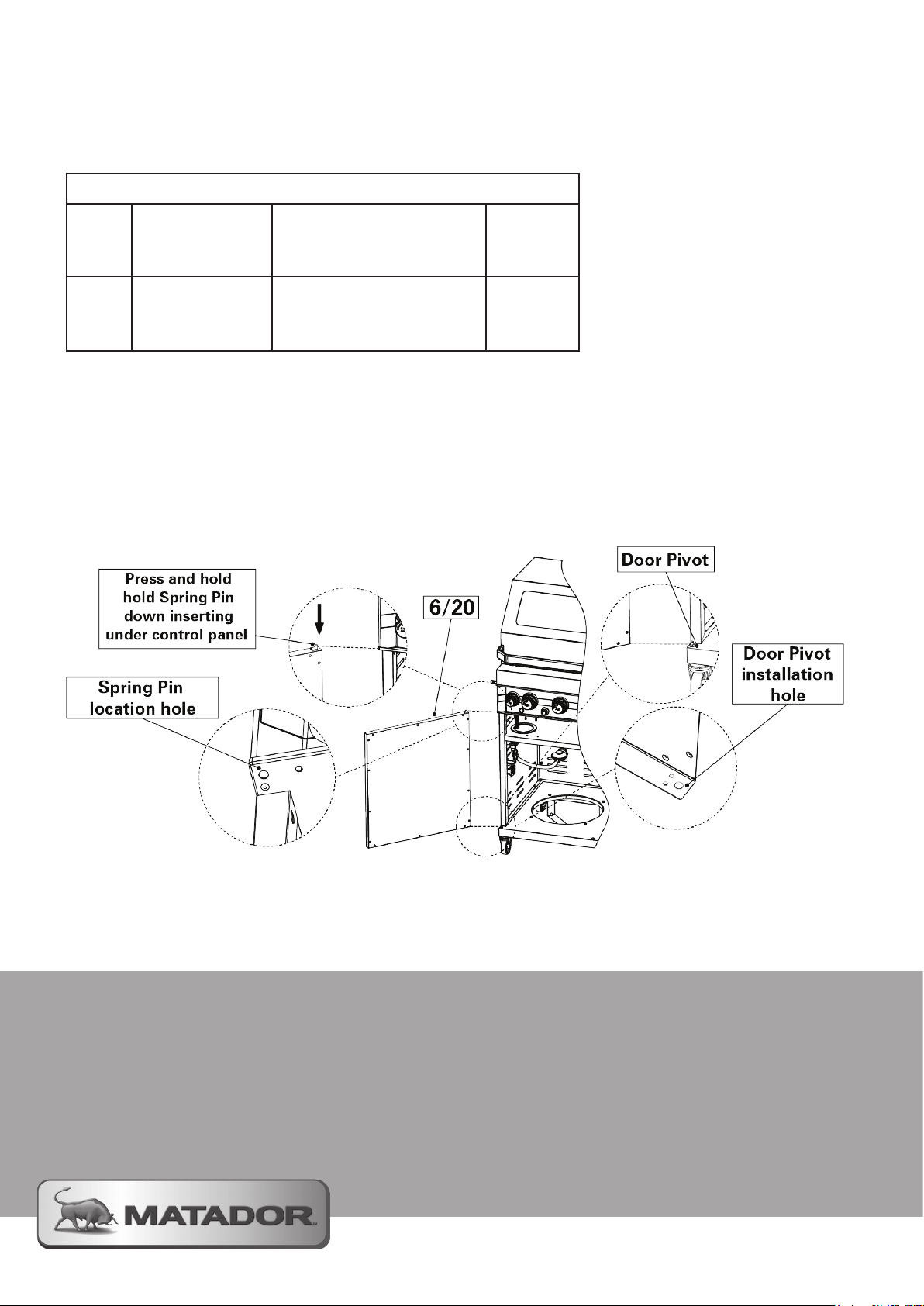
Step 15 - Attach Trolley Doors
ALL MODELS
Parts / Hardware Needed
6
20
15.1 Start with the Trolley Door Left Hand (6) and locate it onto the Door Pivot (L) protruding from the base of
the Trolley Assembly. The bottom side of the door has a hole on one end that locates over the Door Pivot (L)
15.2 Once over the pivot, push hard on the spring pin located on the top face of the door directly above the
Door Pivot. With the pin pushed down slide the Trolley Door Left Hand under the control panel. The control
panel will hold the pin down as you locate it into the installation hole.
15.3 Repeat this process for the Trolley Door Right Hand (20).
Trolley Door
Left Hand
Trolley Door
Right Hand
1
1
Page 37
Assembly Instructions
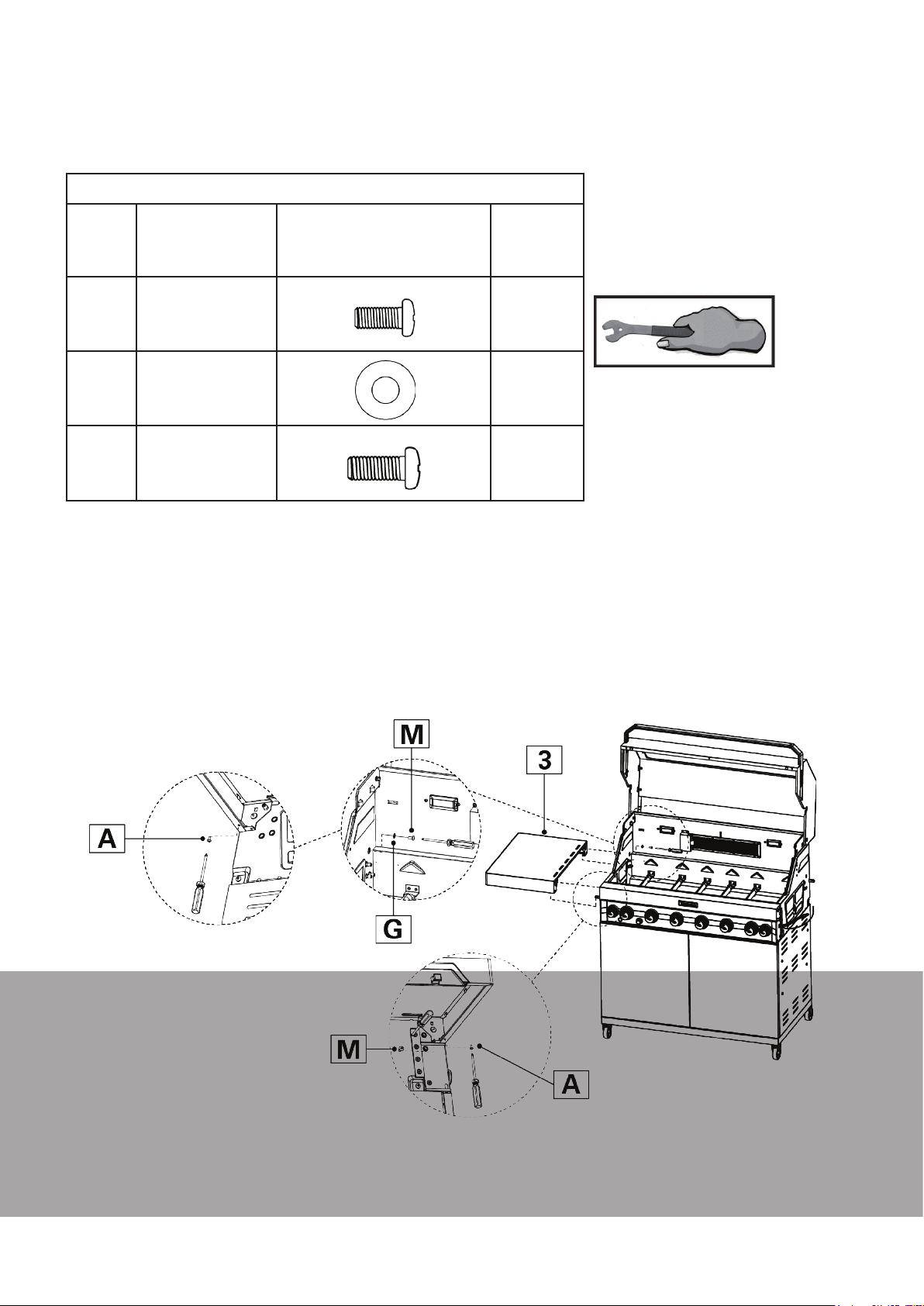
Step 16 - Attaching Left Hand Fixed Side Shelf
4 BNR and 6 BNR MODELS ONLY
Parts / Hardware Needed
3
A
G
M
16.1 Slide the Left Hand Fixed Side Shelf Assembly onto the two square rods protruding from the side of the
Firebox (4)
16.2 Use 2 M4 x 8 mm Screws (A) to attach the Left Hand Fixed Side Shelf (3) to the square rods
16.3 From inside the firebox, screw a M6 x 16mm Screw (M) with a 6mm Flat Washer (G) attached into the
rear bracket of the Left Hand Fixed Side Shelf (3).
16.4 On the front bracket, screw a M6 x 16 mm Screw (M) into the Firebox (4) to finish the attachment.
Left Hand
Fixed Side Shelf
M4 x 8 mm
Pan Head Screw
6 mm
Flat Washer
M6 x 16 mm
Pan Head Screw
1
2
1
2
NOTE:
This stage will require a Phillips
head screwdriver
NOTE: Washer must be used in step 16.3 to avoid damaging the enamel coating of the Firebox
MATADOR INSTRUCTION MANUAL
37
Page 38
Assembly Instructions
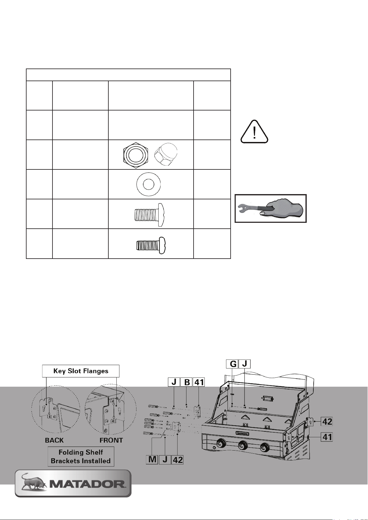
Step 17 - Attaching Folding Shelf Brackets
3 BNR MODEL ONLY
Parts / Hardware Needed
NOTE:
41
Pivot Bracket A
2
This stage will require a Phillips
head screwdriver, adjustible
spanner or and a socket set
42
B
G
J
M
17.1 Take a Pivot Bracket B (42) and secure it to the front of the Firebox (4) on the left hand side with 2 M6 x
12mm Screws (J) and 2 M6 x 16mm Screws (M). Pay attention to the orientation of the bracket and ensure that
key slot flange is on the outside barbecue.
17.2 On the same side of the barbecue attach a Pivot Bracket A (41) at the rear of the Firebox (4). From outside
the Firebox (4) use 3 M6 x 12mm Screws (J) to partially secure the bracket. Again, pay attention to ensuring
the key slot flange is on the outside of the barbecue.
Pivot Bracket B
M6
Domed Hex Nut
6 mm
Flat Washer
M6 x 12 mm
Pan Head Screw
M6 x 16 mm
Pan Head Screw
2
2
2
12
4
Pay attention to the orientation
of the brackets. Make sure the
pivoting flanges with the key
slot are on the outside of the
barbecue.
17.3 From inside the firebox, thread a M6 x 12mm Screw (J) with a 6mm Flat Washer (G) attached through the
firebox and secure to Pivor Bracket A (41) with a 6mm Domed Hex Nut (B).
17.4 Repeat this process for the right hand side of the firebox but you will reverse the position of parts 41 and
42 so that the key slot flanges assemble on the outside faces of the barbecue.
NOTE: Washer must be used in step 17.3 to avoid damaging the enamel coating of the Firebox
Page 39
Assembly Instructions
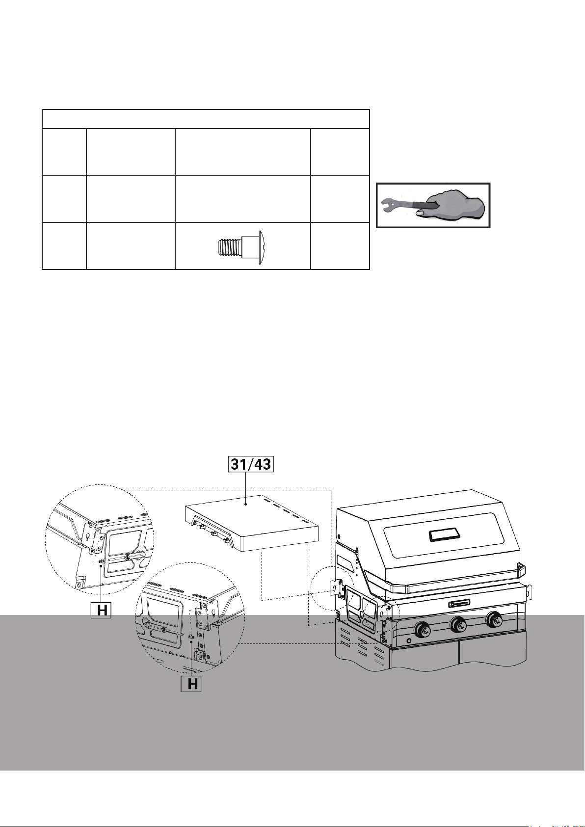
Step 18 - Attaching Folding Shelves
3 BNR MODEL ONLY
Parts / Hardware Needed
NOTE:
31
Folding Right
Hand Side Shelf
1
This stage will require a Phillips
head screwdriver
43
H
4
18.1 Lower the Folding Left Hand Shelf (43) down onto the two Support Brackets (41 & 42) and locate the 2
protruding screws into the top semi-circular notches on the key slot flanges.
18.2 Secure the shelf by fastening 2 M6 Shoulder Screws (H) through the key slot holes on the Support
Brackets (41 & 42)
18.3 Repeat this process for the Right Hand Side of the barbecue using the Folding Right Hand Shelf (31).
TO OPERATE:
• To fold the shelf, directly lift up the shelf to disengage the screw heads from the semi-circular notches
and pivot the shelf downwards.
• To raise the shelf, pivot the shelf up and drop it back down onto the support brackets so that the locking
screws are again engaged again in the top notch details.
Folding Left
Hand Side Shelf
M6
Shoulder Screw
1
4
MATADOR INSTRUCTION MANUAL
39
Page 40
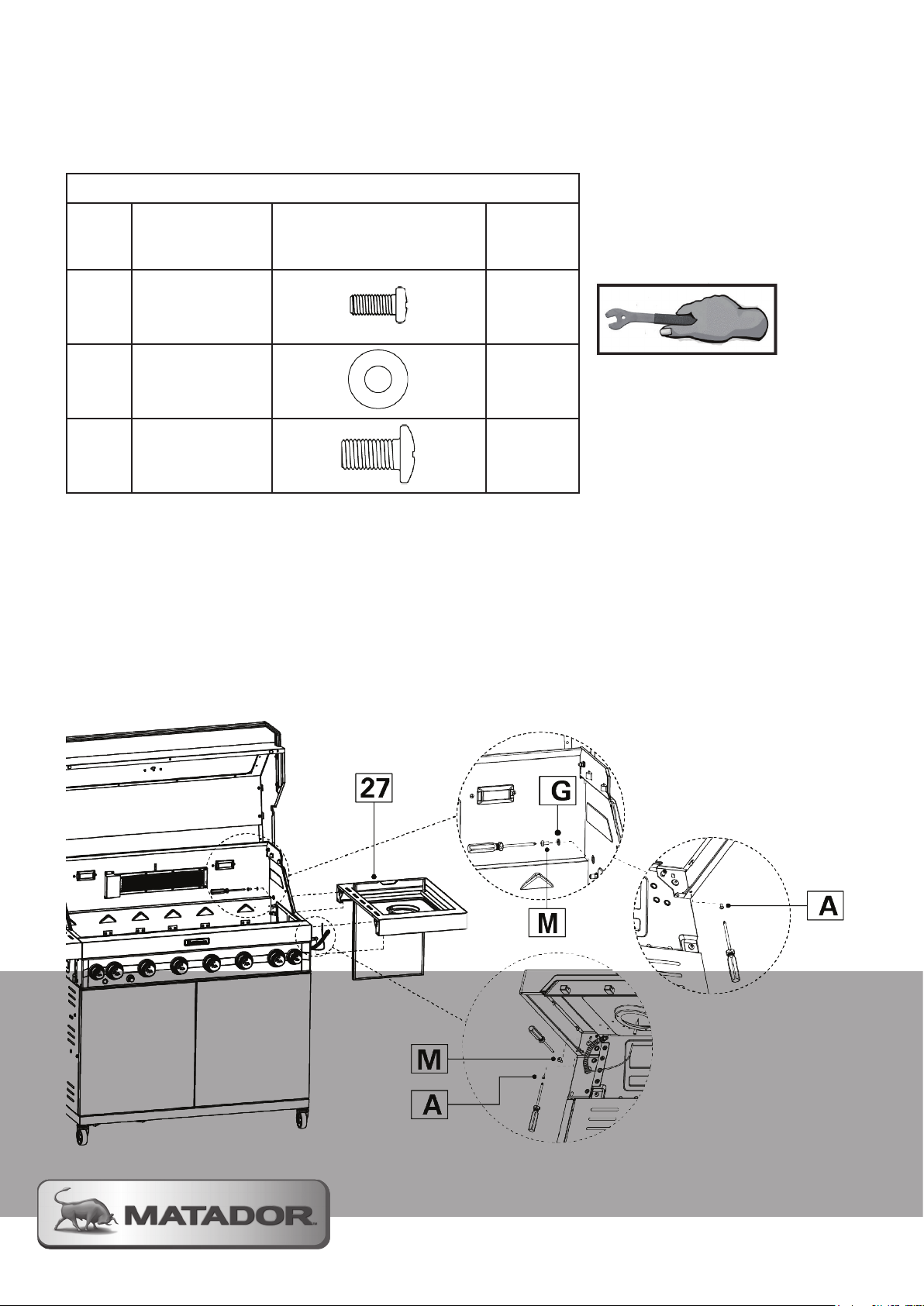
Assembly Instructions
Step 19 - Attaching The Side Burner
4 BNR AND 6 BNR MODELS ONLY
Parts / Hardware Needed
NOTE:
27
Right Hand Side
Burner Shelf
1
This stage will require a Phillips
head screwdriver.
A
G
M
19.1 Slide the Right Hand Side Burner Shelf (27) onto the two square rods protruding from the side of the
Firebox (4)
19.2 Use 2 M4 x 8 mm Screws (A) to attach the Left Hand Shelf (3) to the square rods
19.3 From inside the firebox, screw a M6 x 16mm Screw (M) with a 6mm Flat Washer (G) attached into the
rear bracket of the Left Hand Side Shelf (3).
19.4 On the front bracket, screw an M6 x 16 mm Screw (M) into the Firebox (4) to finish the attachment.
M4 x 8 mm
Pan Head Screw
6 mm
Flat Washer
M6 x 16 mm
Pan Head Screw
2
1
2
Page 41
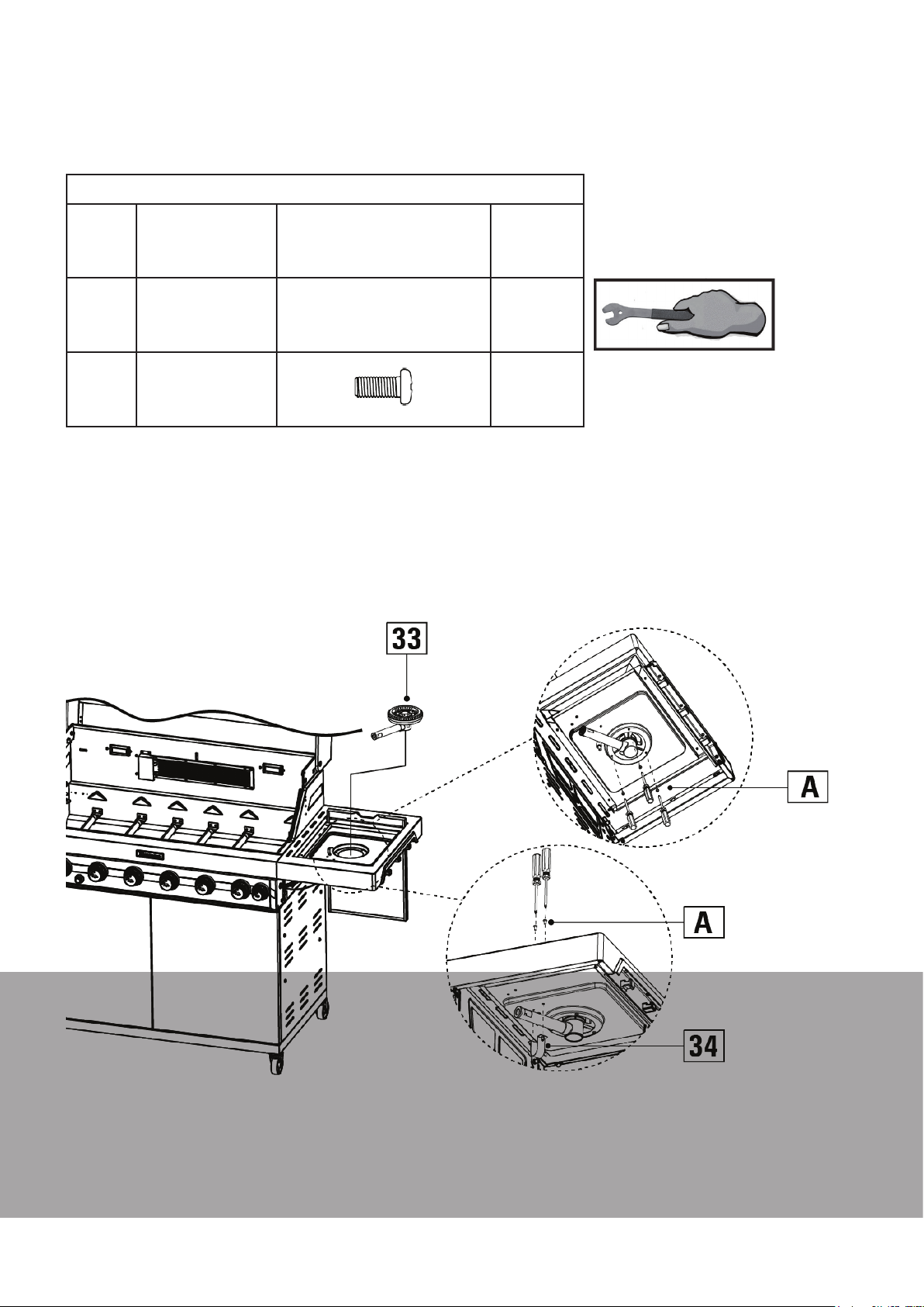
Assembly Instructions
Step 20 - Install Side Burner
4 BNR and 6 BNR MODELS ONLY
Parts / Hardware Needed
NOTE:
33
Side Burner
Assembly
1
This stage will require a Phillips
head screwdriver
34
A
20.1 Lift up the Side Burner Lid and retract it back down into the rear storage slot.
20.2 Take the Side Burner Assembly (33) and lower it through the central hole in the Side Burner Shelf (27).
Turn the burner until the three mounting holes are aligned underneath the shelf.
20.3 Use 3 M4 x 8 mm Screws (A) to secure the Side Burner (33) in place.
20.4 Secure the Side Burner Support Bracket (34) to the underside of the shelf. Use 3 M4 x 8 mm Screws (A)
Assembly to fix the bracket in place. Screw in place from the top side of the shelf
Side Burner
Support Bracket
M4 x 8 mm
Pan Head Screw
1
5
MATADOR INSTRUCTION MANUAL
41
Page 42
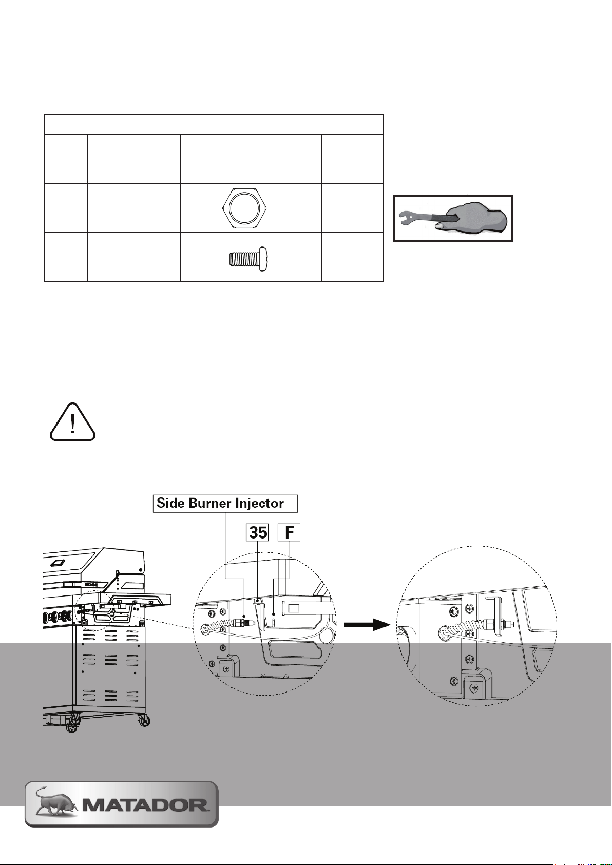
Assembly Instructions
Step 21 - Attaching Side Burner Injector Bracket
4 BNR and 6 BNR MODELS ONLY
Parts / Hardware Needed
35
F
A
21.1 Slide the Side Burner Injector Bracket (35) over the end of the injector hose coming out from the Firebox
(4). Secure the bracket firmly onto the hose with the 7/16” Collar Nut ensure that the top location flange is on
the top.
21.2 Insert the side burner injector inside the end of the induction tube of the Side Burner (33). Once
completely inserted into the Side Burner (33) secure the Side Burner Injector Bracket (35) with 2 M4 x 8mm
Screws (A) from the top side of the assembly.
21.3 Once secure, insert the side burner ignition guide wire into the side burner ignition needle.
Side Burner
Injector Bracket
7/16” Collar Nut
M4 x 8 mm
Pan Head Screw
1
1
2
NOTE:
This stage will require a Phillips
head screwdriver
NOTE: The side burner injector must be completely inserted into the injection tube of the side burner. To
prevent the leaking of gas and injury the injector cannot be exposed
Page 43
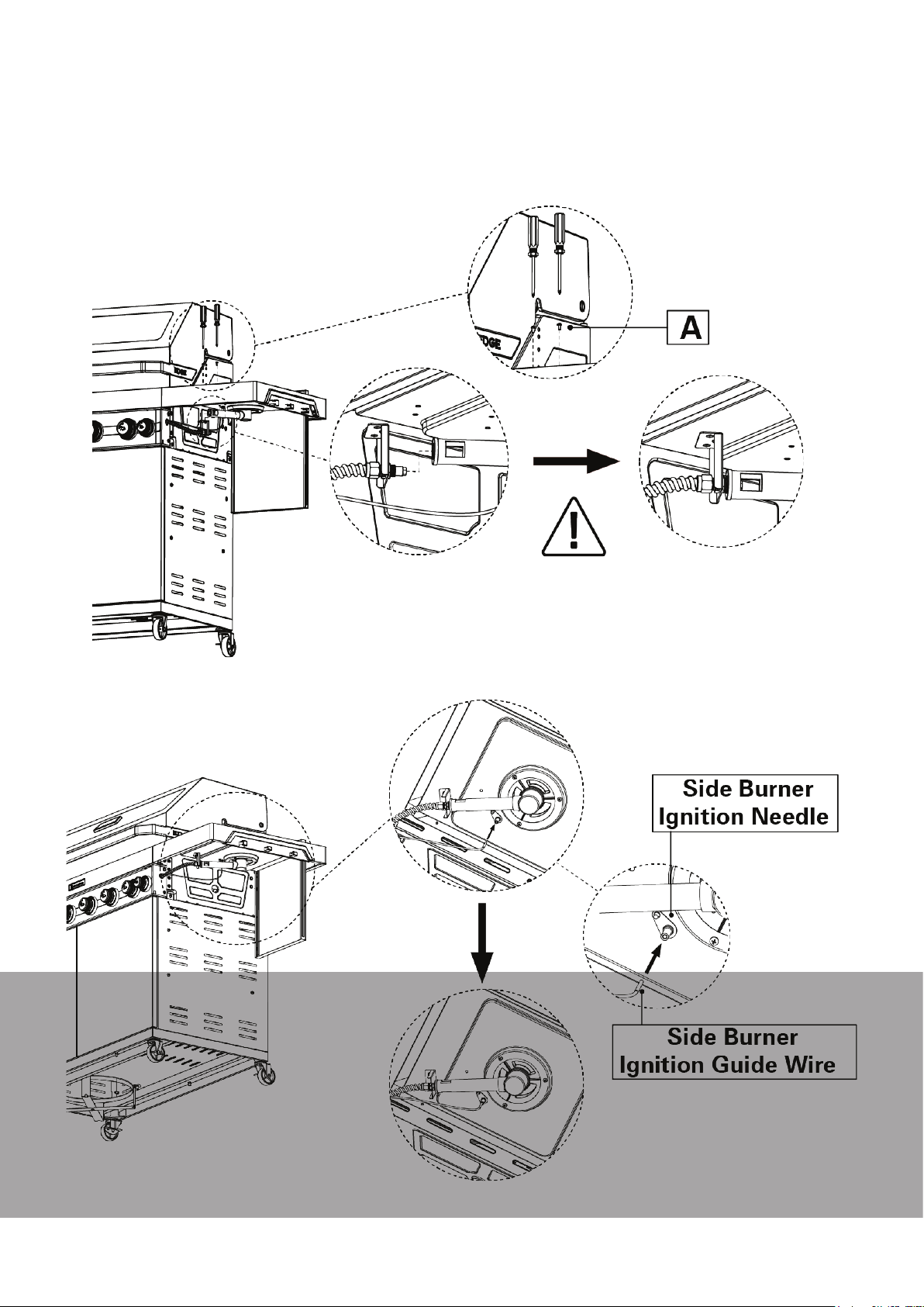
Assembly Instructions
Step 21 - Continued
MATADOR INSTRUCTION MANUAL
43
Page 44
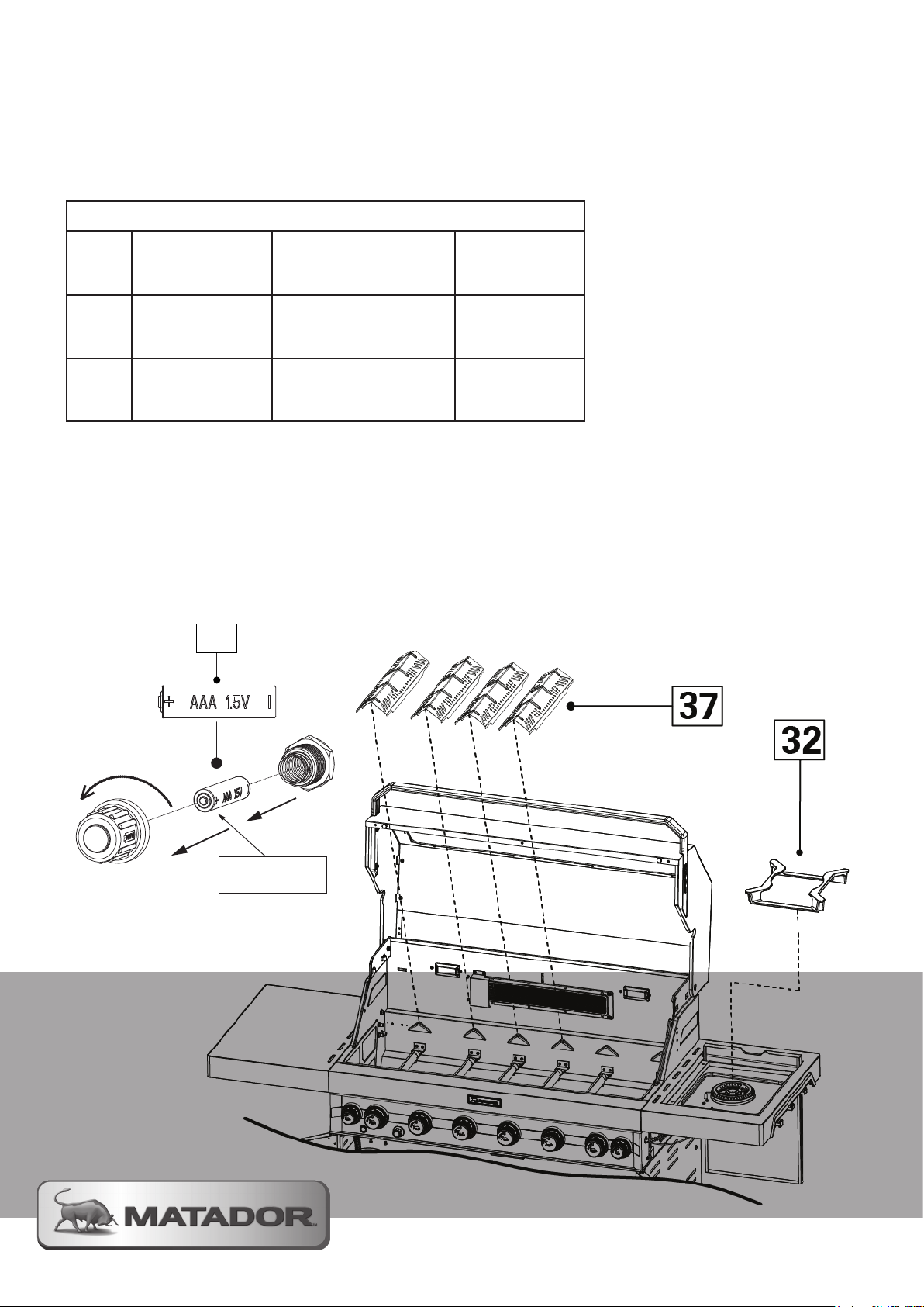
Assembly Instructions
Step 22 - Install Flame Tamers, Side Burner Trivet and
Rear Burner Switch BAttery
ALL MODELS (Flame Tamers) 4 BNR and 6 BNR only (TRIVET)
Parts / Hardware Needed
32
37
44
22.1 Place the Side Burner Trivet (32) over the top of the Side Burner and locate in the recess provided.
22.2 Place the Flame Tamers (37) over the top of the burners starting from the left hand side of the Firebox
(4).
22.2 Unscrew the Rear Burner Ignition Switch and insert AAA Battery (44). Insert with the positive end facing
outwards.
NOTE: Flame tamers must only be used under the Cooking Grates (1) and not under the Solid Cooking Plate
(2)
Side Burner
Trivet
Flame Tamers
AAA Battery
3 / 4 / 6 BNR
0 / 1 / 1
2 / 3 / 4
0 / 1 / 1
44
INSERT BATTERY WITH
‘+’ END FACING OUT
FROM THE BBQ.
Page 45
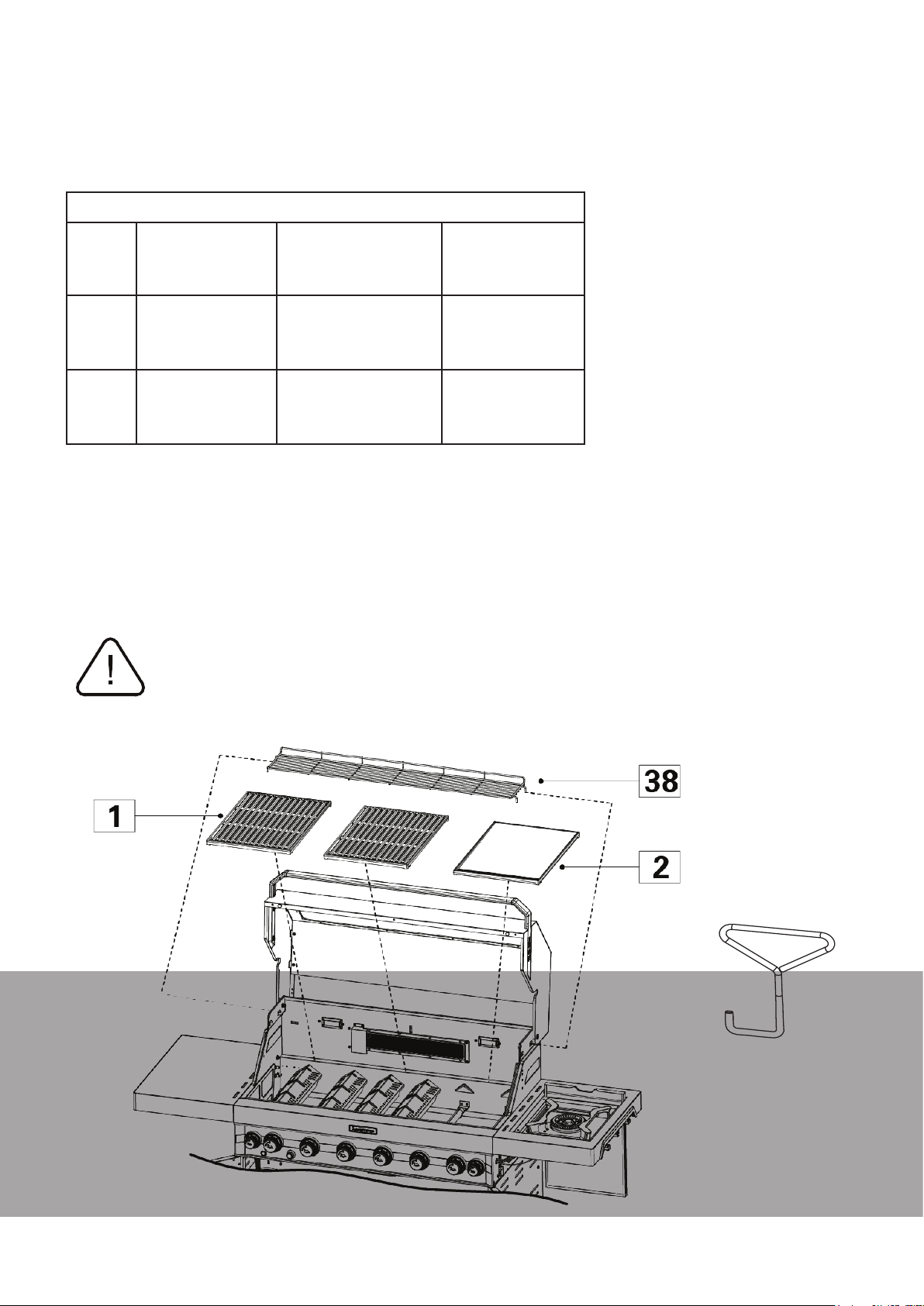
Assembly Instructions
Step 23 - Cooking Surface and Warming Rack
ALL MODELS
Hardware Needed
1
2
38
23.1 Carefully lower and place the Cooking Grate/s (1) into the Firebox (4) above the flame tamer/s on the left
hand side of the barbecue.
23.2 Carefully lower and place the Solid Hot Plate (2) into the Firebox (4) above the burners on the right hand
side of the barbecue
23.3 Locate the Warming Rack’s (38) 4 legs into the 4 resting points located at the top of the Firebox (4)
above the cooking surface.
NOTE: It is important that the Solid Hot Plate is located on the right hand side of the barbecue above the
burners that DO NOT have the flame tamers on them.
Cooking Grate
Solid Hot Plate
Warming Rack
Your EDGE Barbecue comes supplied with a Grate Tool (36) which is design to help you lift the
Cooking Grate (1) from the Firebox (4) when needed for cleaning and maintenance. You must
use this tool to avoid damaging the Cooking Grates (1) with other tools.
3 / 4 / 6 BNR
1 / 1 / 2
1 / 1 / 1
1 / 1 / 1
36
MATADOR INSTRUCTION MANUAL
45
Page 46
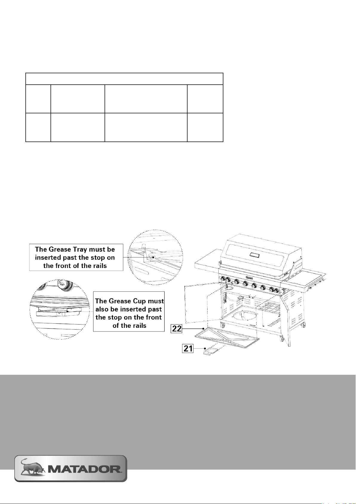
Assembly Instructions
Step 24 - Insert The Grease Tray and Cup
ALL MODELS
Parts / Hardware Needed
21
22
24.1 The Grease Tray (22) and Grease Cup (21) are removed and inserted from the front of your barbecue for
your convenience. To access them you need to open both of the doors on your trolley cabinet.
24.2 Slide the Grease Tray (22) into the two rails that are below the Firebox (4) of your barbecue. Push until
the front of the tray passes over the small stop situated on the front of the rails.
23.3 Once the tray is located take the Grease Cup (21) by its handle and lift it into the location rails in the
centre of the Grease Tray (22) again until it also passes over of the stop on the end of the rails.
Grease Cup
Grease Tray
1
1
Page 47
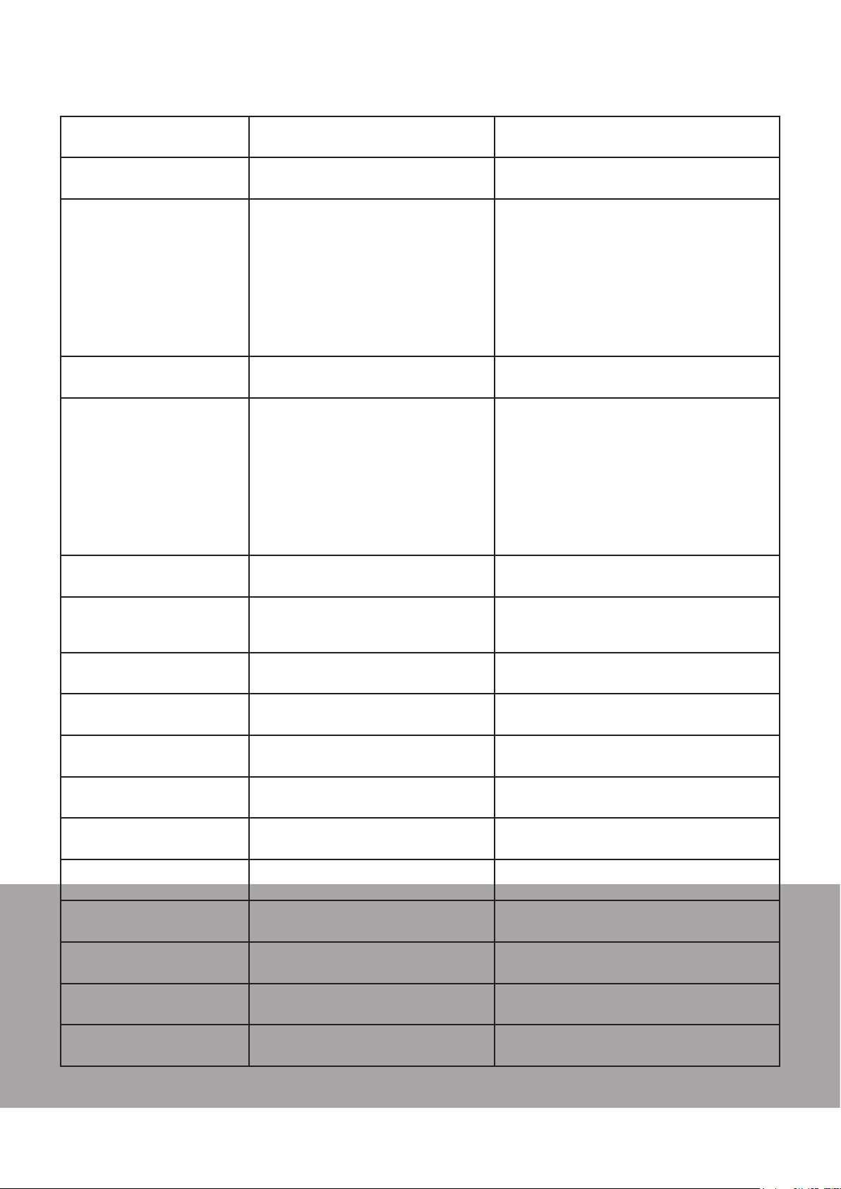
Troubleshooting
PROBLEM CAUSE CHECK
When lighting I smell gas Loose connection or faulty part Check all connections are tight and
perform the leak test of the gas line.
Barbecue will not light No gas flow Check that the valve on the gas cylinder is
turned on.
Check the burner ports are free from
obstructions.
Check all gas injectors are clean and free
of obstructions.
Check all gas connections are secure.
Ensure each burner is positioned
correctly over each gas port.
Turning on gas control too quickly Allow 5 seconds for the gas to flow
through the burner before igniting.
Ignition system not working Check to see visible spark at starter probe
- if no spark is present when control knob
is turned then the unit may need to be
serviced or replaced. Contact your Mayo
Hardware support.
Check that there is a visible flame coming
from the pilot ignition tube.
Check that the pilot ignition tube is not
blocked by spider webs or insect nests.
Burners not assembled correctly Check that burners are correctly
positioned in the barbecue frame.
Burner ports or throat blocked Check that the burner ports are not
blocked by spider webs or insect nests.
Clean out as required.
Barbecue lights but goes
out soon after starting
Low flame level or heat
output
LED lights are not on Power not connected to barbecue Check the barbecue is connected to the
USB will not charge device Power not connected to barbecue Check the barbecue is connected to the
Hood Lights will come on Power not connected to barbecue Check the barbecue is connected to the
Fuel supply turned off Turn gas valve at cylinder.
Gas cylinder low or empty Replace cylinder and carry out leak test.
Kink in the gas hose Check there are no kinks or twists in the
hose.
Windy conditions Make sure barbecue is out of the way of
direct wind.
Burners will not cross light Check you are running on correct gas.
Check gas injector size is correct.
power source and turned on.
power source and turned on.
Faulty charge cable Ensure there is no visible damage to your
charge cable
power source and turned on.
Globes may need replacing Replace globe in light fitting
MATADOR INSTRUCTION MANUAL
47
Page 48
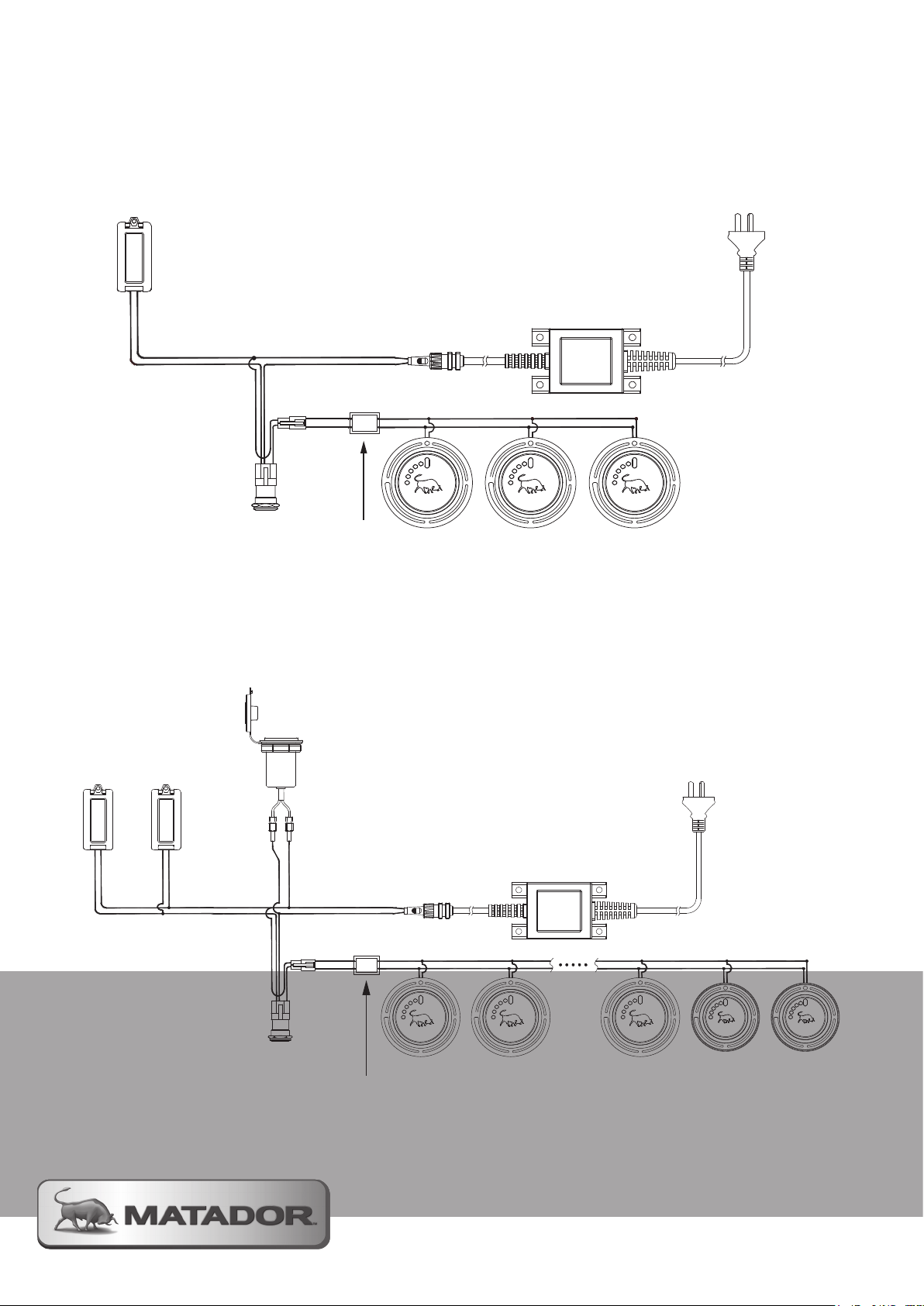
Technical Information
Hood Lights
Knob Lights
Switch
230-240V AC
Power voltage
step-down plate
12V AC
Transformer
USB Ports
Hood Lights
Knob Lights
Switch
230-240V AC
Power voltage
step-down plate
12V AC
Transformer
3 Burner Wiring Diagram
4 and 6 Burner Wiring Diagram
Page 49
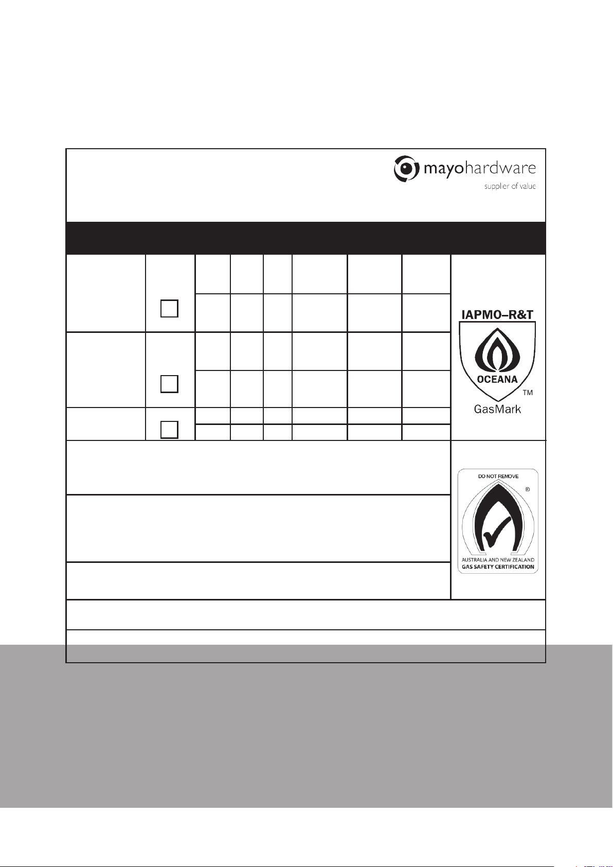
Technical Information
14cm W x 15cm H
Label 1 - Data label for EDGE Trolley BBQs
Black on Silver Stock
Version 5.0 - 09.06.2020
Data Specification Label
Mayo Hardware Pty Ltd
4 Secombe Place Moorebank
New South Wales, 2170
T: 1300 360 211
www.mayohardware.com.au
NAME
MODEL
INJECTOR
(mm)
MATADOR EDGE
Trolley BBQ 6 BNR
MATADOR EDGE
Trolley BBQ 4 BNR
MATADOR EDGE
Trolley BBQ 3 BNR
Gas Supply Pressure, ULPG
Min: 2.70kPa; Max 3.45kPa
Gas Type: NZ: Universal LPG or NG
AUS: ULPG or NG
GB0102
GB0101
GB0100
ULPG:
NG:
ULPG: 2.75
NG: 1.00
ULPG:
NG:
BBQ
S/B
R/B
BBQ
S/B
R/B
BBQ
S/B
R/B
BBQ
S/B
R/B
BBQ
BBQ
Gas Supply Pressure, NG: 1.13kPa - 2.0kPa
Complies to: Standard AS/NZS 5263.1.7
INPUT: 230-240 Vac 50Hz pf=0.97
OUTPUT: 12Vac 2.5A 30VA
a. Use only with a GFI protected circuit
b. Use only extension cords approved for outdoor use marked with W-A and rated
for the power of this appliance
.
1.09
1.30
0.85
1.69
2.08
1.35
1.09
1.30
0.85
1.69
2.08
1.35
1.09
1.69
PRESSURE
(kPa)
2.75
1.00
2.75
1.00
INP/BURN
(Mj/h)
6 x 15.3
1 x 21.1
1 x 8.7
6 x 12.8
1 x 18
1 x 8
4 x 15.3
1 x 21.1
1 x 8.7
4 x 12.8
1 x 18
1 x 8
3 x 15.3
3 x 12.8
TOTAL
(Mj/h)
121.60
102.80
91.00
77.20
45.90
38.40
IAPMO APPROVAL
GMK10658
MINIMUM CLEARANCE FROM COMBUSTIBLE MATERIALS:
From Top of BBQ: 1000mm, From Sides and Rear: 1000mm
SERIAL NUMBER: DAT E:
FOR OUTDOOR USE ONLY
MATADOR INSTRUCTION MANUAL
49
Page 50
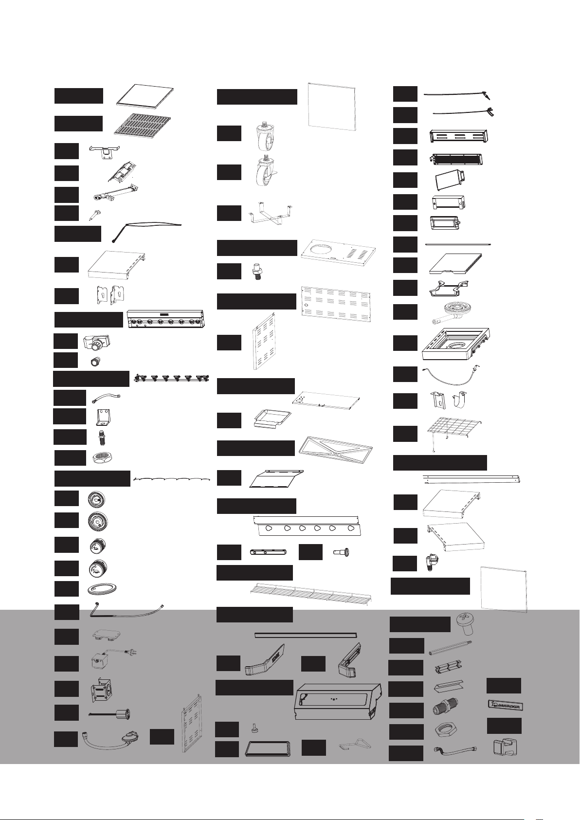
EDGE Spare Parts
6BNR BARBECUE PARTS SHOWN FOR REFERENCE
1/65
2/66
3
4
5
6
7/68
8
9
10/69/70
11
12
13/73/75
127
126
125
128
14/74/76
2
3
42
27/78/79
28
29
30
31/83/84
32
33/85/86
34
35/87/88
36
37/89/90
38
50
51
52
53
54
55
56
57
58
59
60
61
62
63
64
67/121/122
3
2
15
16
17
18
19
20
21
22
23
24
25
26
39/91/92
40
42/93/95
43/94/96
44
46/97/98
47
48
41
45
49
71
72
77
80/81/82
99/100
105
109
110
129
130
131
132
133
Page 51

EDGE Spare Parts
Spare
Part
1 3B / 6B Cooking Grate GB0111 32 Door Axle Set GB0143
2 3B / 6B Solid Hot Plate GB0112 33 6B Trolley Back Panel GB0144
3 Flame Tamer Support Bracket GB0113 34 Trolley Right Hand Panel GB0145
4 Flame Tamer GB0114 35 6B Trolley Top Panel GB0146
5 Main Burner Assembly GB0115 36 Grease Cup GB0147
6 Main Burner Injection Needle GB0116 37 6B Grease Tray Assembly GB0148
7
8 Fixed Left Side Table Assembly GB0118 39 6B Heat Shield GB0150
9 Control Panel Brackets GB0119 40 Side Burner Support GB0151
10 6B Control Panel Assembly GB0120 41 Hood Axle GB0152
11 Rear Burner Ignition Switch GB0122 42 6B Warming Rack GB0153
12 Light Switch GB0123 43 6B Hood Handle GB0154
13 6B Gas Assembly GB0124 44 Hood Handle Base RH GB0155
14 6B Knob Connection Wire GB0125 45 Hood Handle Base LH GB0156
6B / 4B Light Connection Wire
Assembly
Name Part
Code
GB0117 38 Firebox Thermal Baffle GB0149
Spa r e
Part
Name Part
Code
15 Small Control Knob Base GB0126 46 6B Hood Assembly GB0157
16 Large Control Knob Base GB0127 47 Hood Buffering Pads (Set) GB0158
17 Small Control Knob GB0128 48 Hood Thermometer GB0159
18 Large Control Knob GB0129 49 Grate Lifter GB0160
19 Trolley Top Panel Seal Ring GB0130 50
20 Rear Burner Bellow GB0131 51
21 Door Magnet GB0132 52 Rear Burner Back Cover GB0163
22 Power Adaptor GB0133 53
23 USB Socket Bracket GB0134 54
24 USB Socket Assembly GB0135 55 Light Cover GB0166
25 Hose and Regulator Assembly GB0136 56 Hood Light GB0167
26
27 6B Trolley Left Door Assembly GB0138 58 Side Burner Lid GB0169
Trolley Left Hand Panel
Assembly
GB0137 57 Side Burner Lid Axle GB0168
Rear Burner
Thermocouple Assembly
Rear Burner Ignition
Needle
Rear Infrared Burner
Assembly
Rear Burner Ignition
Needle Cover
GB0161
GB0162
GB0164
GB0165
28 Castor GB0139 59 Side Burner Trivet GB0170
29 Locking Castor GB0140 60 Side Burner Assembly GB0171
30 Gas Cylinder Base GB0141 61 Side Burner Shelf Assy GB0172
31
6B Trolley Bottom Panel
Assembly
GB0142 62
Side Burner Ignition
Needle Assembly
MATADOR INSTRUCTION MANUAL
GB0173
51
Page 52
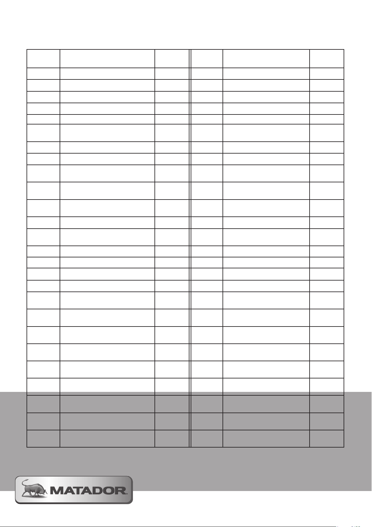
EDGE Spare Parts
Spare
Part
63 Side Burner Injector Brackets GB0174 89 4B Grease Tray Assembly GB0200
64 Trolley Wire Shelf Assembly GB0175 90 3B Grease Tray Assembly GB0201
65 4B Solid Hot Plate GB0176 91 4B Heat Shield GB0202
66 4B Cooking Grate GB0177 92 3B Heat Shield GB0203
67 4B Grease Slot Assembly GB0178 93 4B Warming Rack GB0204
68
69 4B Control Panel Assembly GB0180 95 3B Warming Rack GB0206
70 3B Control Panel Assembly GB0181 96 3B Hood Handle GB0207
71
72
73 4B Gas Assembly GB0184 99
74 4B Knob Connection Wire GB0185 100 3B Trolley Hardware Pack GB0212
75 3B Gas Assembly GB0186 105
76 3B Knob Connection Wire GB0187 109 Grease Tray Bracket GB0220
3B Light Connection Wire
Assembly
3B Left Folding Shelf
Assembly
3B Right Folding Shelf
Assembly
Name Part
Code
GB0179 94 4B Hood Handle GB0205
GB0182 97 4B Hood Assembly GB0208
GB0183 98 3B Hood Assembly GB0209
Spa r e
Part
Name Part
6B/4B Trolley Hardware
Pack
6B Rotisserie Extension
Rod
Code
GB0210
GB0216
77 Rear Burner Injector Assembly GB0188 110 Grease Tray Outer Bracket GB0221
78 4B Trolley Left Door Assembly GB0189 121 6B Grease Slot Assembly GB0232
79 3B Trolley Left Door Assembly GB0190 122 3B Grease Slot Assembly GB0233
80
81
82
83
84
85
86
87
88
6B Trolley Right Door
Assembly
4B Trolley Right Door
Assembly
3B Trolley Right Door
Assembly
4B Trolley Bottom Panel
Assembly
3B Trolley Bottom Panel
Assembly
4B Trolley Back Panel
Assembly
3B Trolley Back Panel
Assembly
4B Trolley Top Panel
Assembly
3B Trolley Top Panel
Assembly
GB0191 125 Gas valve connector GB0236
GB0192 126 Inlet Port Bracket GB0237
GB0193 127 Connected Corrugated Pipe GB0238
GB0194 128 Gas Valve Connector Nut GB0239
GB0195 129
GB0196 130 Side Burner Connector Nut GB0241
GB0197 131
GB0198 132 Matador Badge GB0121
GB0199 133 Bottle Opener Hook GB0211
Side Burner Injector
Assembly
Side Burner Corrugated
Pipe
GB0240
GB0242
Page 53

Warranty
MATADOR WARRANTY
Thank you for purchasing one of our quality Matador BBQs.
YOUR MATADOR BBQ IS COVERED AGAINST DEFECTS FOR A PERIOD OF 5 YEARS FOR PARTS AND
LABOUR, REPAIR OR REPLACEMENT.
THIS WARRANTY EXCLUDES SURFACE RUST AND DAMAGE CAUSED BY ABUSE OR NEGLECT.
CONDITIONS OF THE WARRANTY
• The BBQ must be operated and maintained in accordance with the instructions supplied in the
operating manual.
• Any repair does not extend the warranty period.
• Any parts other than original Matador parts will void this warranty.
THIS WARRANTY IS GIVEN BY:
Mayo Hardware Pty Ltd
ABN 73 000 032 806
4 Secombe Place
Moorebank
NSW 2170
Australia
www.mayohardware.com.au
Phone (Aus) 1300 360 211
Phone (NZ) 09 415 6240
Email: [email protected]
RETAIN A COPY OF YOUR RECEIPT AND THE BELOW INFORMATION FOR YOUR RECORDS ALSO
Date of purchase: ……………………………………………………………………………………………………………
Purchased from: ……………………………………………………………………………………………………………..
Location: ………………………………………………………………………………………………………………………
Model name and number: ………………………………………………………………………………………………….
Batch code: …………………………………………………………………………………………………………………...
Receipt number: ……………………………………………………………………………………………………………..
Note: The manufacturing date can be found printed on this operating manual and is also located on the Data
Specification Label that is applied to the inside of the Trolley Door of your Matador BBQ.
MATADOR INSTRUCTION MANUAL
53
Page 54

Warranty
MAKING A CLAIM
Any claim under this warranty must be made within 5 years of the date of purchase of the product.
To make a claim under warranty, take the product (with proof of purchase) to any Bunnings store (see www.
bunnings.com.au for store locations) or contact Mayo Hardware Pty Ltd [email protected].
Mayo Hardware Pty Ltd bears reasonable, direct, expenses of claiming under warranty. You may submit
details and proof to Mayo Hardware Pty Ltd for consideration. The warranty covers manufacturer defects in
materials and workmanship under normal use. Refer to care and use instructions for correct cleaning and
maintenance advice.
This warranty is provided in addition to other rights and remedies you may have under law: our goods
come with guarantees which cannot be excluded under the Australian Consumer Law. You are entitled to
replacement or refund for a major failure and to compensation for other reasonably foreseeable loss or
damage. You are also entitled to have the goods repaired or replaced if the goods fail to be of acceptable
quality and the failure does not amount to a major failure.
The warranty excludes damage resulting from product misuse or product neglect. The warranty covers
domestic use only and does not apply to commercial applications.
WHAT IS NOT COVERED
• Removal or re-location costs.
• Liability will only be accepted for loss or damage during transit if at the time the product was being
transported by Bunnings or a Bunnings approved contractor.
• Lack of maintenance, abuse, neglect, misuse, accidental or improper installation of this appliance.
• Scratches, dents, surface rust, discolouration caused by heat, abrasive chemical cleaners or chipping or
porcelain enamel parts.
• Damage caused by exposure to the elements such as weather, hail, insects, grease and fat fires.
• Rusting of the cooking or solid grate.
• Cleaning and wear and tear.
• Commercial use of this product.
• Halogen globes
• Ignition battery
• Unauthorised modifications or repairs during the warranty period.
FOR TECHNICAL ASSISTANCE
Refer to the troubleshooting section of this operating manual or contact the Mayo Hardware through the below
details:
Phone (Aus) 1300 360 211
Phone (NZ) 09 415 6240
Email: [email protected]
FOR SPARE PARTS
Contact Mayo Hardware through the below details:
Phone (Aus) 1300 360 211
Phone (NZ) 09 415 6240
Email: [email protected]
Page 55

Register your BBQ
REGISTERING YOUR BBQ FOR WARRANTY
We recommend you register your Matador BBQ to make it easier for you in the event that you ever have any
warranty claims.
To register your warranty please scan the QR CODE below to be taken to our online registration page.
We recommend you register your Matador BBQ for potential warranty claims.
You can also register your Matador BBQ by emailing us a copy of your BBQ’s details together with a copy of
your purchase receipt to [email protected].
MATADOR INSTRUCTION MANUAL
55
Page 56

PB0150f
Visit www.matadorbbqs.com.au
For technical and warranty support call
1300 360 211 (AUS)
09 415 6240 (NZ)
Your purchase receipt will be required for warranty claims.
For spares parts contact your local Bunnings Warehouse.
 Loading...