

Page 1

052_03
Installation, operating and
maintenance instructions
GAS PASTA COOKER
03/2006
ABE0001
ACE0005
Page 2

Models and dimensions page 3
Data of appliances 4
Technical data 4-5
Operating instructions 6
Construction, equipment installed
and safety devices 6
Assembly 6
Location 6
Legal and technical requisites 6
Installation 6
Installation procedure 6
Gas connection 6
Plumbing connection 6
Gas venting 6
Commissioning the appliance 7
Before commissioning the appliance 7
Start-up 7
Testing the power rating 7
Checking input pressure 7
Checking power rating using
the volumetric method 7
Checking power rating when using
LP gas 7
Checking the pilot light 8
Checking the primary air 8
Checking the functions 8
Note for the installer 8
Running the appliance on other types
of gas page 8
Replacing the main burner nozzle 8
Pilot injector replacement 8
Adjusting the low flame 8
Maintenance 8
Replacing parts 9
Ignition plung 9
Gas tap 9
Thermocouple 9
Using the appliance 10
First-time use of the appliance 10
Ignition 10
Turning the pilot burner on 10
Turning the main burner on and adjusting
the temperature 10
Turning the appliance off 10
Turning the appliance off during
normal operation 10
Turning the appliance off
in an emergency 10
What to do if something goes wrong or if
not using the appliance for a long time 10
Taking care of the appliance
frequency of maintenance 11
Daily cleaning 11
Precautions during use 11
Protection of stainless steel 11
Warning 12
INDEX
052-03 - Gas pasta cooker
2
Page 3
052-03 - Gas pasta cooker
3
A
B
C
D
E
F
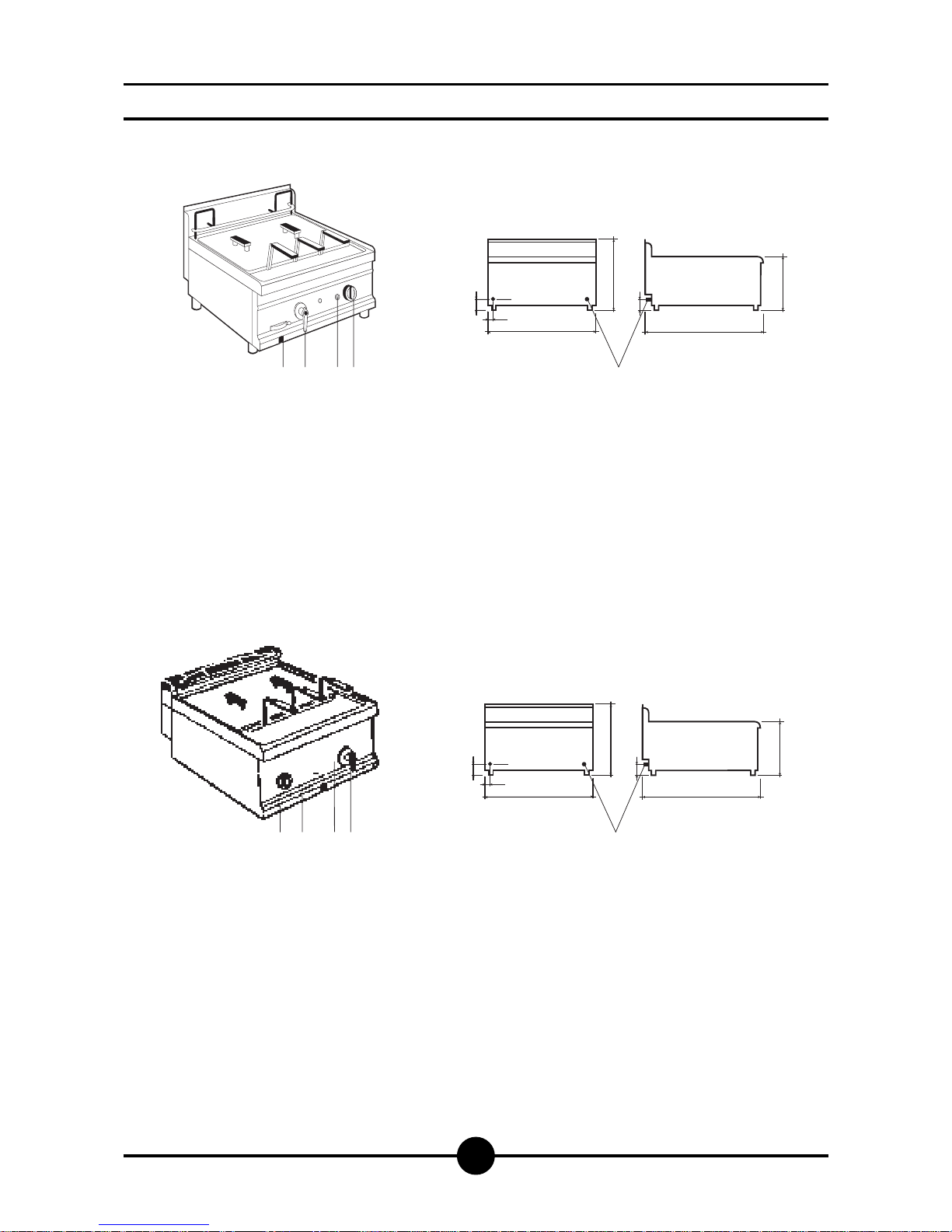
Drainage tap
Inlet tap
Gas control knob
Piezo electric lighter
Water inlet
Gas connection
Models and dimensions
55
21
600
400
E
F
55
655
300
BDAC
F
55
21
600
400
E
F
55
700
300
BDAC
F
ABE00001
600 x 650 x 300
weight approx.33,6 kg
ACE00005
600 x 700 x 300
weight approx35,6 kg
Page 4
052-03 - Gas pasta cooker
4
3 - TECHNICAL DATA
2 - DATA OF APPLIANCES
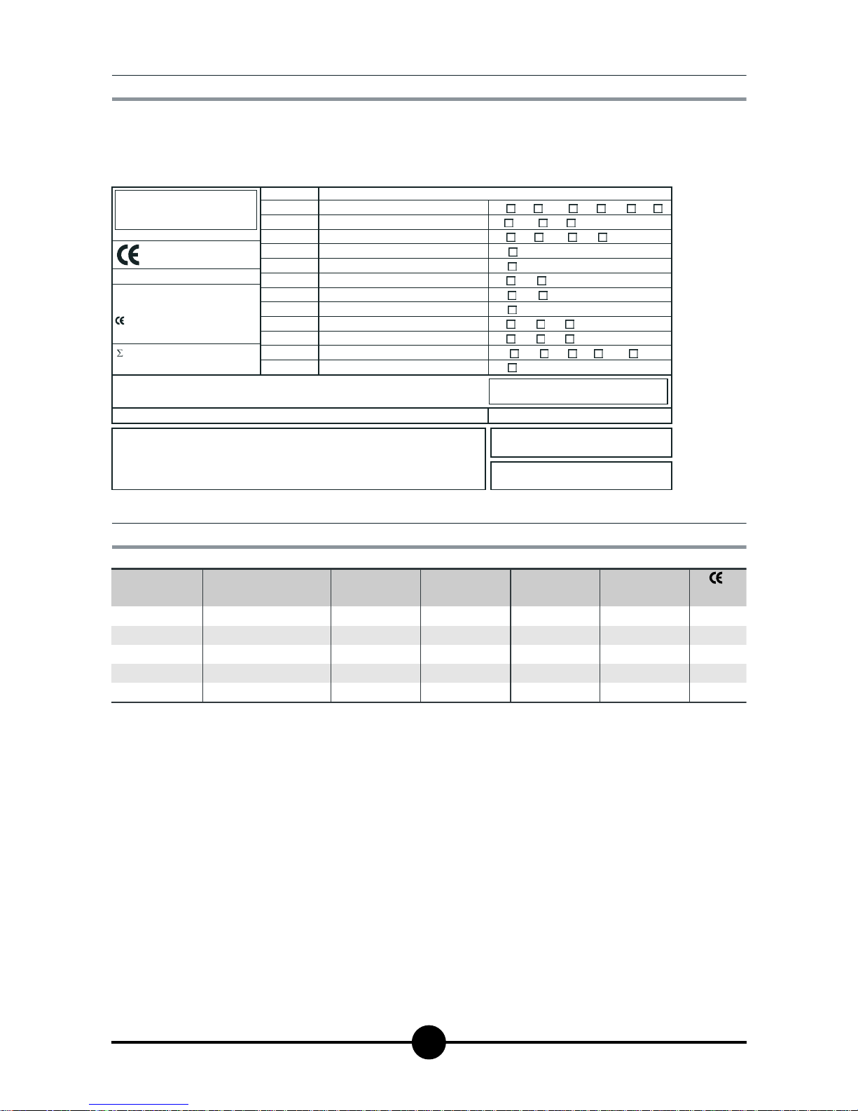
The instructions contained in this manual apply to our gas
cookers in the II2H3+ category (see table on page 5).
The data plate is located on the front of the appliance and
on the control panel. It contains all necessary reference
data such as the name of the manufacturer, input pressure, gas type setting, etc.
0051
TIPO/TYPE
CAT/KAT GAS/GAZ G30 G31 G20 G25
II2H3B/P P mbar 30 30 20 -
II2H3+ P mbar 30 37 20--
II2H3+ P mbar 28 37 20 -
25II2L3B/P P mbar 30 30
II2ELL3B/P P mbar 50 50 20 20
II2E+3+ P mbar 28 37 20 25
II2H3B/P P mbar 50 50 20 -
I2E P mbar - - 20 -
--II2H3B/P P mbar 30 30
II2H3+ P mbar 28 37 20 -
--
--
I3B/P P mbar 30 30
I3+ P mbar 28 37
SE FI DK CZ SK SI
IT CH PT
ES IE GB GR
NL
DE
FR BE
AT CH
LU
EE LV LT
EE LV LT
NO MT CY IS HU
CY
MOD.
MOD.
ART.
N.
N.
Qn kW
m3/h
MADE IN ITALY
Predisposto a gas: - Gas preset: - Prevu pour gaz:
Eingestelt für Gas: - Preparado para gas: -
Geschuckt voor:
V AC kW Hz
THE APPLIANCE MUST BE CONNECTED IN COMPLIANCE WITH THE LAWS IN FORCE
AND INSTALLED IN A WELL-VENTILATED ROOM. READ THE INSTRUCTION MANUALS
BEFORE INSTALLING AND USING THE APPLIANCE.
THE APPLIANCE MUST BE INSTALLED BY QUALIFIED PERSONNEL.
G30/G31 28/37 mbar
G20 20 mbar
Model
ABE00001
ACE00005
N.
51BQ2902
51BQ2902
External dimensions
(LxPxH+H1) - mm
Plumbing
connection - mm
Water
outlet
Gas connection Tank
capacity (lt)
600 x 650 x300
600 x 700 x 300
Ø 12
Ø 12
front panel
front panel
R 1/2" ISO R228
R 1/2" ISO R2283434
Page 5

052-03 - Gas pasta cooker
5
Primary air distance “A”
Methane gas G20
Liquid gas G30/G31
close
open
TABLE 1
Model
Category
Construction type
Air necessary for combustion
Nominal thermal power
Minimum thermal power
Connection pressure
Methane gas 2H
Liquid gas 3+
Gas connection values
Methane gas 2H
Liquid gas 3+
Nozzles Ø 1/100 mm
Main burner
G20
G30/G31
(HuB = 9.45 kWh/m
3
) m3/h
(HuB = 12.87 kWh/kg) kg/h
Nominal capacity
Low flame
Nominal capacity
Low flame
G20
G30/31
20 mbar
30/37 mbar
II2H3+
A
m
3
/h
kW
kW
2x150
adjustable
2x95
80
No. of nozzles, pilot burner
G20
G30/G31
36
19
18
8
3.2
ABE00001
ACE00005
0.847
0.631
Page 6

052-03 - Gas pasta cooker
6
Construction, equipment installed
and safety devices
Robust steel frame, with 4 legs (adjustable in height).
18/10 chrome-nickel steel outer panelling, tank in AISI
316.
The water is heated by 2 tubular stainless steel burners,
which is resistant to thermal and mechanical stress.
The pilot burner has fixed injector.
The combustion chamber and flues are made of electro-galvanised steel sheeting.
The temperature is set using the safety taps provided.
It goes from low (minimum) to high (maximum) through
a range of easily selectable intermediate levels.
ASSEMBLY
Location
The appliance should be installed in a well ventilated
room, and under a range hood.
The appliance can be installed on its own or alongside
other equipment.
If the appliance is to be installed near inflammable walls, a minimum distance of 50 mm. around the sides and
back should be allowed.
If this is impossible, take proper steps to ensure the installation is safe, such as fitting tiles or heat-reflecting
material to the walls
Before connecting up the appliance to the gas supply,
check on the data plate that the appliance is fitted for
the type of gas available.
If not, consult paragraph “Running the appliance on
other types of gas”, page 8.
Legal and technical requisites
During assembly, the following legal and technical requisites should be adhered to:
- relevant national legislation;
- local building and fire safety regulations;
- worksheet “Technical rules for installing gas”;
- worksheet “Technical rules for LP gas”;
- worksheet “Gas installations in industrial kitchens”;
- industrial injury legislation;
- local Gas Board regulations;
- current CEI regulations.
INSTALLATION
Assembly, installation and maintenance, i.e.: assembly,
connecting the gas supply, checking power rating,
transforming or adapting the appliance to run on other
types of gas, and commissioning, must all be done by
contractors authorised by the local Gas Board in accordance with local and national legislation.
Before doing anything else, seek advice from your Gas
Board.
Installation procedure
To level the appliance correctly, adjust the height of the
four legs.
Gas connection
The R 1/2” gas off-take can either be permanently fixed
to the mains or made detachable using a standard
adaptor.
If flexible hose is used, it must be in stainless steel.
After completing connection, check for leaks using a
special leak-detector spray.
Plumbing connection
A rigid or flexible pipe may be used for connection to
the water supply.
The inlet pipe has a 12 mm diameter.
Gas venting
These appliances are A construction type, thus no gas
venting is required.
For advice on ventilating the premises where the appliance is installed, observe current regulations.
OPERATING INSTRUCTIONS
Page 7
052-03 - Gas pasta cooker
7
Before commissioning the appliance
Before commissioning the appliance, remove the protective wrapping.
Thoroughly clean the work-surface and the outside of
the appliance using lukewarm water and detergent.
With a damp cloth eliminate all traces of the rust-proofing applied in the workshop then dry with a clean cloth.
Start-up
Before starting the appliance up, check that its specifications (category and type of gas used) match those of
the family and group of the gas available locally.
If not, adapt the appliance to the gas family or group required (see paragraph “Running the appliance on other
types of gas” page 8).
To start the appliance up, see the instructions for regular use.
Testing the power rating
Use the specific nozzles for the nominal capacity on the
appliance.
Capacity can be of two types:
- nominal, as given on the data plate;
- minimum.
These nozzles are shown in table 1 in the assembly instructions.
The following are the operating pressure tolerances to obtain the nominal power according to the agreed nozzles:
- from 15 to 22.5 mbar for gases of the second family
- from 25 to 45 mbar for gases of the third family
(propane).
The appliance will not work outside the above pressure
threshholds.
To adjust the capacity to its minimum value, use the data in tables 1 (Gas Flow Regulation table).
If you wish to check the nominal capacity further, you
may do so using a gas meter according to the so-called
”volumetric method”.
It is normally enough, however, simply to check that the
nozzles are functioning correctly.
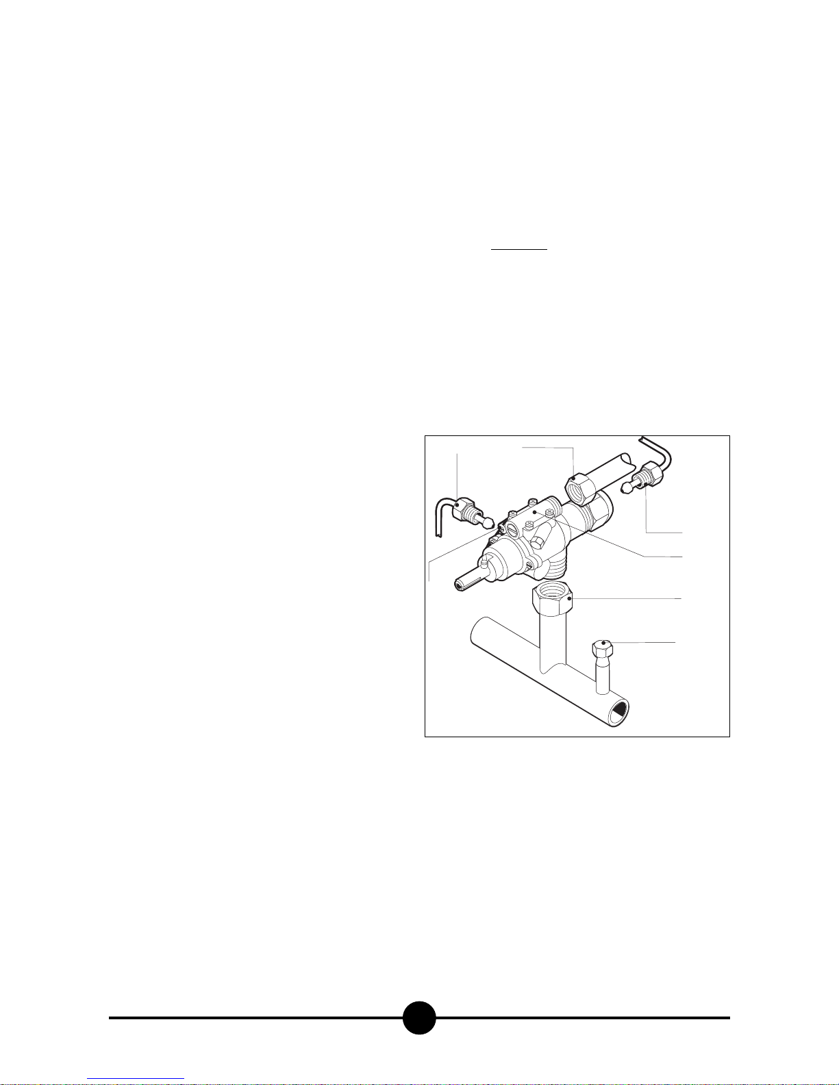
Checking input pressure (Fig. 3)
Input pressure should be measured using a gauge (e.g.
a gooseneck pipe, min. resolution 0.1 mbar).
Remove screw (22) from the pressure socket and connect it to the tube on the gauge; after measuring, the
screw should be retightened absolutely airtight (22).
Checking power rating using the
volumetric method
Using a gas meter and a chronometer, you can read
the volume of gas output per time unit.
The correct volume will be the value of “E” expressed in
litres per hour (It/hr) or litres per minute (It/min).
The following formula is used to calculate the value of “E”:
Capacity should only be measured when the appliance
is at a standstill.
The heat value can be obtained from your local Gas
Board.
To obtain the nominal and minimum capacities in relation to the nominal pressure, consult table (1- Gas Flow
Setting).
WARNING
It is not possible to adjust nominal capacity in advance.
Checking power rating when using
LP gas
Check that the type of nozzles used match table 1 specifications.
Check that the output pressure regulator installed collaterally to the plant conforms to the specifications laid
down in paragraph "Testing the power rating" (see data
plate and measure the pressure).
Capacity
Heat value
E =
COMMISSIONING THE APPLIANCE
4
22
6
1
5
3
2
3
Page 8

052-03 - Gas pasta cooker
8
Checking the pilot light
When correctly adjusted, the pilot light flame will completely surround the thermocouple and will not flicker.
Checking the primary air
The appliance can be adjusted. Air volume flow is correct when there is sufficient protection against the flame rising when the burner is cold or light-back when it
is hot. Position the ring at measurement “A” (Fig. 1) indicated in table 1 for type of gas.
Checking the functions
- Start the appliance in accordance with the instructions;
- Check the gas tubes for leaks;
- Check that the flame on the main burner lights
properly and is correctly formed, even on low;
- Check that the pilot light is correctly regulated;
- Draw up a servicing and maintenance contract.
Note for the installer
- Explain and demonstrate to the user how the machine works according to the instructions, and hand him
this manual.
- Remind the user that any structural alterations to the
room housing the appliance may affect the combustion air supply. Once the alterations have been completed, the appliance and its functions should be thoroughly checked.
Running the appliance on other types
of gas
When changing to another type of gas, e.g. from natural
to LP, or to another gas group, consult the “TECHNICAL
DATA” table to determine the correct nozzles to use.
The nozzles for the main burners and pilot light for different types of gas, marked in 100ths of mm, are in a case supplied with the appliance.
When the appliance has been transformed or adapted,
recheck its functions as described in paragraph
"Checking the functions".
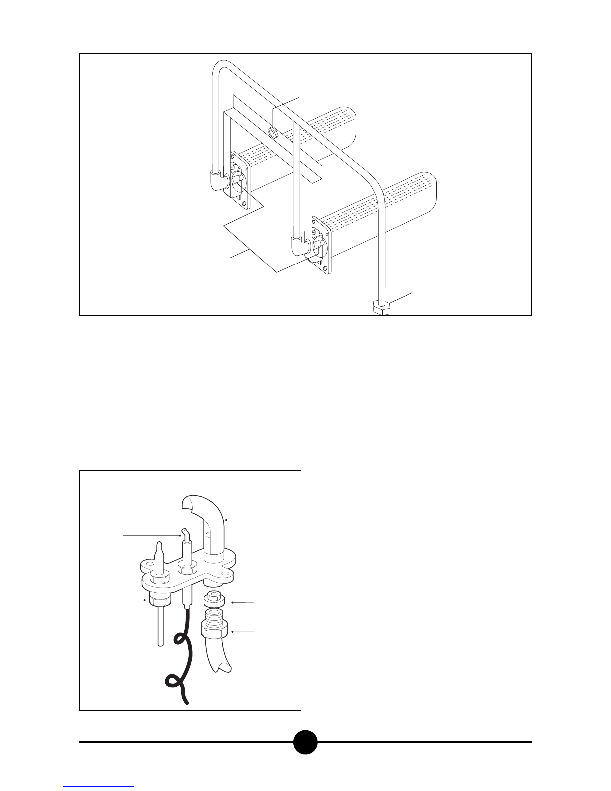
Main burner injector replacement
(Fig. 1)
To replace the injector (30) dismount the front panel.
Dismount the holding injector collector unscrewing the nut
31 and the nut 32 on the gas cock. With a 12 spanner unscrew the holding injector and replace them with new one
(see schedule “technical data”). Reassemble in the reverse order.
Pilot injector replacement (Fig. 2)
To replace the pilot injector (36) dismantle the front panel
with a screwdriver and unscrew the screw nut (35), now the
injector can be reached inside the body pilot, replace it
with a new one (see technical data) when finished screw
again the screw nut (35).
Adjusting the low flame (Fig. 3)
Referring to the “TECHNICAL DATA” table, set the low flame screw (2) as follows:
- if the appliance is to run on LP gas, tighten the low flame
screw as far as it will go;
- if the appliance is to run on natural gas, turn the low flame screw while simultaneously adjusting the primary air:
- read off the setting in It/min which corresponds to the
heat value (calculated by the “Volumetric Method”) in
the Gas Flow Setting Table (2); start the appliance up
according to the instructions;
- after allowing the appliance to run for same mins., turn
the knob to low and set minimum gas flow by turning
screw (2) (to the right = gas flow decreases; to the left =
gas flow increases).
MAINTENANCE
The following maintenance programme should be carried
out at least once a year:
- Check that all the safety and setting devices are working
properly;
- Check that the burners are working properly with regard
to:
- ignition
- combustion safety;
- Check the functions of the appliance as described in paragraph "Checking the functions".
Page 9
052-03 - Gas pasta cooker
9
REPLACING PARTS
All parts must be replaced by authorised technicians only!
To replace the following parts, first remove the control
knobs, slide out the fat tray and remove the control panel (after unscrewing its fixing screws).
Ignition plug (Fig. 2)
The ignition plug (37) is removed by loosening screws
(36). Disconnect the ignition lead, loosen the lock nut
and insert a new plug.
Gas tap (Fig. 3)
Loosen the gas piping and thermocouple hoses, then
loosen the screws fixing the gas supply to the gas ramp
and insert a new tap.
Thermocouple (Figs. 2 & 3)
Loosen the screws fixing the thermocouple (38) to the
gas (6) tap and the pilot burner (34); insert the new
part.
After replacing the parts, fit the control panel and its
parts back in the right order.
WARNING
Every time a replacement involving gas input parts
is made, recheck all functions and test for leakage.
35
36
34
29
37
2
30
31
32
1
Page 10
START-UP
FIRST-TIME USE OF THE APPLIANCE
Important!
Before using the appliance for the first time, thoroughly clean the tank with lukewarm water and detergent, using a soft cloth to eliminate all traces of swarf;
dry with a clean cloth.
IGNITION
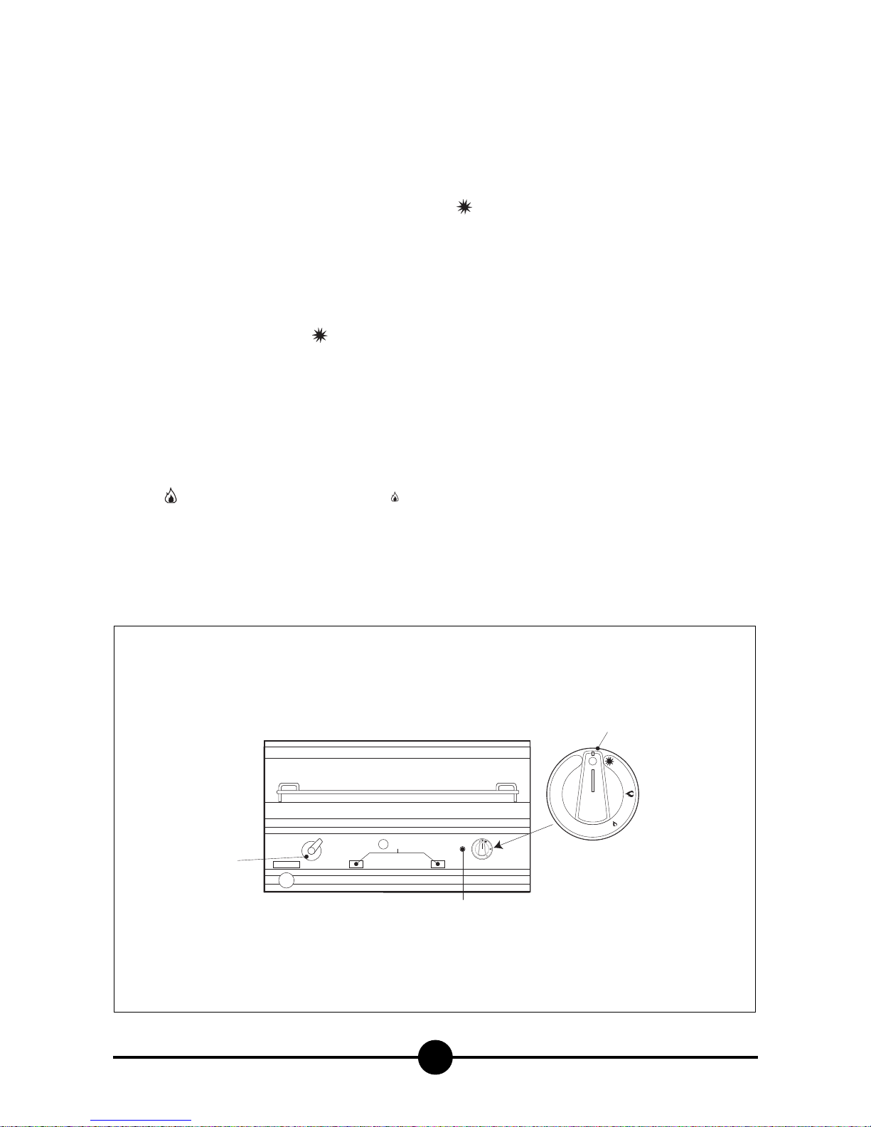
Turning the pilot burner on (Fig. 4)
Press knob (4) and turn it to the left .
Keep the knob pressed down while repeatedly pressing
piezo ignition button (6) until you can see through aperture
(10) on the combustion chamber that the flame has caught.
Keep the knob pressed down for another 15-20 seconds;
if the flame goes out after the knob is released, start again.
Turning the main burner on and
adjusting the temperature (Fig. 4)
To light the main burner, turn the knob to the right until it is
on ‘high’ , or else continue until it reaches low ; the
heating capacity must be set between these two positions.
TURNING THE APPLIANCE OFF
Turning the appliance off during
normal operation
To turn the main burner off only, simply turn the knob
to ; this way only the pilot burner will stay on.
To turn the appliance off completely, turn the knob to ●;
this will turn the pilot burner off as well.
Turning the appliance off in an
emergency
In an emergency turn off the gas supply.
What to do if something goes wrong
or if not using the appliance for a
long time
If the appliance is not to be used for a long time, or if it
breaks down or works incorrectly, close the tap to the gas
mains located outside the appliance. clean thoroughly
(see cleaning and protection of steel).
If anything goes wrong, call the aftersales department.
USING THE APPLIANCE
052-03 - Gas pasta cooker
10
6
3
5
9
4
Page 11

052-03 - Gas pasta cooker
11
TAKING CARE OF THE APPLIANCE
FREQUENCY OF MAINTENANCE
Giving the appliance a thorough clean every day (after turning it off) will keep it in perfect working order and make it
last longer.
Daily cleaning
Frequently clean the surfaces using a damp cloth; water
and soap or common detergents may be used provided
they do not contain abrasives or chlorine-based sub-
stances, such as sodium hypochlorite (bleach), hydrochloric acid (muriatic acid), or other solutions: stainless steel
is quickly and irreversibly corroded by these products.
Under no circumstances use the above-mentioned products to clean the floor under the equipment or nearby, as
fumes or any drops may produce similar destructive effects on the steel.
Only rub in the direction of the satin finish.
Rinse thoroughly with clean water and dry carefully.
Never use running water, as this could infiltrate into the inner parts.
Food stains and encrusted food particles:
wash with hot water before they harden. Should food particles have already become hard, use water and soap or
chlorine-free detergents, if necessary using a wooden
spatula or fine stainless steel wool: rinse and dry thoroughly.
Scale encrustations:
scale deposits on the bottom of tanks, pans, etc. should
be removed using descaling products on the market and
following the relative instructions.
Scratches:
should the surfaces become scratched, they must be
smoothed using extra fine stainless steel wool or abrasive
sponges made of fibrous synthetic material, rubbing in the
direction of the satin finish. Rinse and dry thoroughly.
Never use wire wool for cleaning stainless steel or leave it
in contact with the steel, as very small ferrous deposits
could remain on the surface and cause the formation of rust by contamination.
Precautions during use
Sauces and condiments:
all the stainless steel containers used for notoriously acid
ingredients (vinegar, salt, lemon juice, tomatoes, etc.)
should be thoroughly washed to remove any residue.
In particular salt solutions should not be left to evaporate
or dry on the stainless steel surface.
Never use coarse cooking salt which, being heavy, deposits on the bottom without dissolving completely and over
a period of time can therefore cause points of contact with
consequent corrosion.
It is therefore advisable to add salt in small amounts to water which is already boiling, or to dissolve it in a separate
container; never add it to cold water in the tanks and certainly never put it into an empty tank.
Whenever the tanks are not being used, they should preferably remain uncovered.
Protection of stainless steel
Should the equipment not be used for a certain period of
time, clean the external stainless steel surfaces and when
they are completely dry, protect by spreading over them a
thin film of vaseline oil, or better still specific products to
be found on the market.
Apart from giving the steel a uniform, polished appearance, these products prevent penetration of humidity and
dirt which can also cause corrosion.
These products, basically consisting of a mixture of oily
substances and detergents, are now available in easy-touse, practical spray cans.
Page 12

052-03 - Gas pasta cooker
12
WARNING
DUE TO ITS POLICY OF CONTINUAL PRODUCT IMPROVEMENT, THE MANUFACTURER RESERVES THE RIGHT
TO MAKE ANY CHANGES DEEMED NECESSARY.
THE MANUFACTURER CANNOT BE HELD RESPONSIBLE IF THE INSTRUCTIONS CONTAINED IN THIS MANUAL ARE NOT OBSERVED.
 Loading...