

Page 1
- 1 -
fa
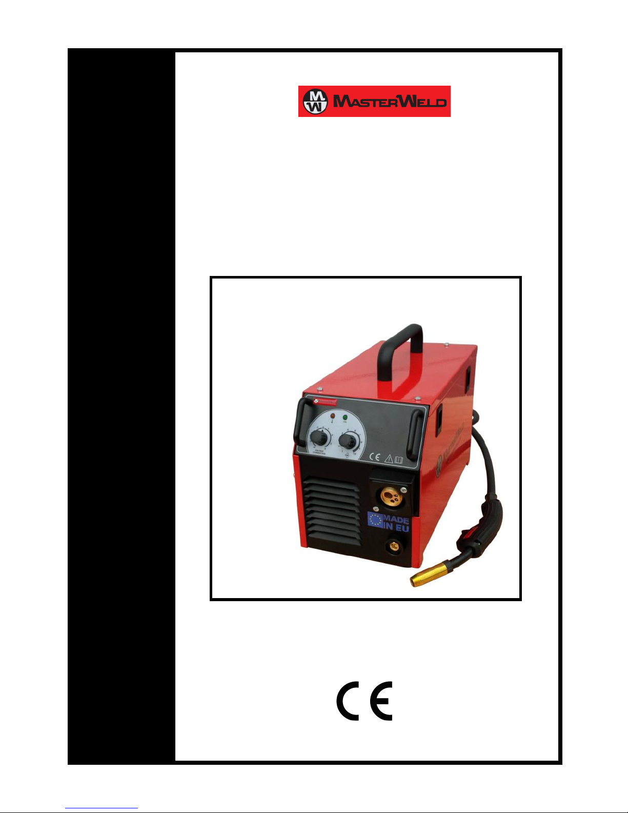
MW2040/2050 MIG EURO
MMaasstteerrwweelldd MMWW22004400//22005500 IInnvveerrtteerr MMIIGG PPaacckkaaggee
EENN -- IInnssttrruuccttiioonn ffoorr uussee aanndd mmaaiinntteennaannccee
MMAADDEE IINN EEUU
Page 2

- 2 -
E N G L I S H
Contents
Introduction
Description
Technical data
Safety standards
Description and installation
Cable connections
Controlling and indicating elements
Principle of MIG/MAG welding
Maintenance
The pointing out of any difficulties and their elimina-
tion
Side cover assembly and disassembly procedure
Welding torch replacement procedure
Ordering spare parts
Official inspection procedure
Table for setting of wire feed rate (for reference
only)
Key to graphic symbols
Graphic symbols on the production plate
Spare parts and list of pulleys
Electrical diagram
List of spare parts
Troubleshooting and repair guide
Testing certificate
Introduction
Thank you for purchasing a Masterweld product, you
have invested in a quality product manufactured in
Europe.
Before using the equipment you should carefully
read the instructions included in this manual.
In order to get the best performance from the system and ensure that its parts last as long as possible,
you must strictly follow the usage instructions and
the maintenance regulations included in this manual.
In the interest of customers, you are recommended
to have maintenance and, where necessary, repairs
carried out by the workshops of our service organisation, since they have suitable equipment and specially trained personnel available. All our machinery and
systems are subject to continual development. We
must therefore reserve the right to modify their
construction and properties.
Description
Machines 2040 and 2050 are a simple portable welding apparatus for the MIG/MAG welding method
suitable both for professional and DIY use. It is a
welding apparatus with ‘flat’ characteristics. This
concerns the welding in inert gas protective atmosphere, where the filler metal is supplied in a form of
‘endless’ wire into the welding bath by the wire feed
mechanism. This method is very productive and
particularly suitable for welding of structural and
low-alloy steel types.
Machine 2040 is available in two versions - with
fixed welding torch and earthing cable and with
euro connectors. Machine 2080 is available only
with euro connectors.
Lightweight and small, the welding apparatus features in its high efficiency. A plastic handrail is used
for easy transport. The device can be suitably supplied with power from a standby generator, e.g. on
building sites. Welding parameters can be easily
adjusted on the apparatus, welding voltage and wire
feed rate are adjustable by a single control element
at the same time according to the welded material
thickness. The control element is used for fine voltage corrections that determine the arc length (weld
temperature). If the correct value is set, it will not be
necessary to change it any more even if there is
a need to weld a material more or less thick. The
apparatus is optimally adjusted for welding of steel
Page 3
- 3 -
with the 0.8 mm wire. However, also 0.6 mm or 1.0
mm wire diameters or tubular wires can be used.
NOTE: The apparatus is designed for the use of steel
wires only!
The welding power supply, wire dispenser and wire
feed mechanism are located in a single compact tin
box. The welding apparatus meets the relevant requirements all standards and regulations of the
European Union and the Czech Republic.
NOTE: The apparatus is designed for the industrial
use.
Temperature-rise tests have been conducted at the
ambient temperature and loading factor of 40°C has
been determined by the calculation.
Safety standards
Welding machines must be used for welding and not
for other improper uses. Never use the welding
machines with its removed covers. By removing the
covers the cooling efficiency is reduced and the
machine can be damaged. In this case the supplier
does not take his responsibility for the damage incurred and for this reason you cannot stake a claim
for a guarantee repair. Their use is
permitted only by trained and experienced persons. Comply with the safety instructions and warnings shown in
this User Guide!
COMPLY WITH THIS USER GUIDE!
Adequate safety devices and equipment protecting
against injury must be used during the welding operations.
Welding inverters must be solely for welding operations by the MIG method; they are not intended for
other nonconforming use.
The device may be used only under the operating
conditions and at place specified by the manufacturer. The welding apparatus must not be used in confined spaces (such as in a crate, vessel, etc.). Do not
place the welding apparatus on wet surfaces! Always
check the condition of power supply and welding
cables before any welding operation; damaged or
unsuitable cables must be replaced immediately!
Welding operations with damaged cables may result
in serious injuries or damage to the welding apparatus. The cables must not be in contact with sharp
edges or hot spots.
Insulate yourself from the welding current circuit by
the use of suitable protective clothing. Avoid any
welding operations while in wet clothing! Do not
place the welding torch or welding cables on the
welding apparatus or other electric equipment.
The welding power supply with the IP23S protection
class is not designed for outdoor use while raining,
unless they are placed under a shed.
DANGERS WHILE WELDING AND SAFETY INSTRUCTIONS FOR MACHINE OPERATORS ARE STATED:
EN 05 06 01/1993 Safety regulations for arc welding
of metals. EN 05 06 30/1993 Safety rules for welding
and plasma cutting. The welding machine must be
checked through in regular inspections according to
EN 33 1500/1990. Instructions for this check-up, see
§ 3 Public notice ČÚPB number 48/1982 Digest.
Table1
Technical data
2040 MIG
2050 MIG EURO
Mains voltage 50 Hz
1~230 V ± 15%
1~230 V ± 15%
Welding current range
20-150 A CO
2,
20 - 170 A Ar+CO2
20-170 A CO
2,
20 - 190 A Ar+CO2
Output voltage settings
22 - 31 V
22 - 31 V
Duty cycle 35%
150 A / 21.5 V
170 A / 22.5 V
Duty cycle 60%
120 A / 20 V
140 A / 21 V
Duty cycle 100%
100 A / 19 V
120 A / 20 V
Mains current / input 60%
20 A / 4.6 kVA
22 A / 5 kVA
Wire feed speed
1-11 m/min
1-12 m/min
Mains protection – slow
16 A
16 A
Power supply cable
2.5 mm2, length 2.4 m
2.5 mm2, length 2.4 m
Temperature class
F (155°C)
F (155°C)
Solid welding wire (Fe)
Ø 0.6 – 1.0 mm
Ø 0.6 – 1.0 mm
Tubular welding wire (Fe)
Ø 0.8 – 1.0 mm
Ø 0.8 – 1.0 mm
Max. size of wire reel
Ø 200 mm
Ø 200 mm
Insulation class
IP 23 S
IP 23 S
Dimensions LxWxH
470 x 200 x 310 mm
470 x 200 x 310 mm
Weight
14 kg / 13 kg
13 kg
Operating temperature
-10°C to +40°C
-10°C to +40°C
Storage temperature
-20°C to +55°C
-20°C to +55°C
Page 4
- 4 -
SECURITY OF WORK WHILE WELDING OF METALS
CONTAINING LEAD, CADMIUM, ZINK, MERCURY
AND GLUCINUM
Make specific precautions if you weld metals containing these metals:
Do not carry out welding processes on gas, oil,
fuel etc. tanks (even empty ones) because there
is the risk of an explosion. Welding can be car-
ried out only according to specific regulations!
In spaces with the risk of an explosion there are
specific regulations valid.
ELECTRIC SHOCK PREVENTION
This apparatus is an electrical device
presenting a serious danger of injury
or fatal accident if it is handled unprofessionally or negligently by person
coming into contact with it.
Welding apparatuses must be operated and handled
only by qualified and properly trained persons. The
operator must observe the requirements of the
following standards EN 60974-1, EN 050601, 1993,
EN 050630, 1993 and all other safety provisions so
that his/her safety and safety of third persons is
guaranteed. All connections must comply with the
current regulations and standards, namely EN
332000-5-54, EN 60974-1 and accident prevention
related legislation.
This apparatus is the Class I device that may be supplied with power only from the mains socket outlet
connected with the protective conductor that is
consequently connected to the equipment (the
conductor must not interrupted in any case - e.g. in
an extension cable). If not, there is a serious danger
of electric shock.
Please make sure that the apparatus is properly
earthed and connect with the earth also the work
area and the weldment.
If not properly covered, the apparatus is not designed for any outdoor work while raining.
Do not conduct any welding operation under wet
conditions or in a wet environment or in rain. Do not
use welding torch, welding or power supply cables of
insufficient cross-sections. Always check the welding
torch, welding or power supply cables and make sure
that their insulation is intact and if the conductors
are not loose in the connections. Cables and socket
outlets must be checked in regular intervals for their
compliance with the relevant safety codes and
standards. Do not use the apparatus with missing or
damaged covers!
If consumable parts are to be replaced (e.g. in the
welding torch), switch the apparatus off using the
mains switch.
All repair and maintenance procedures may be
carried out only if the apparatus is disconnected
from the mains!
All repairs, replacements and adjustments may be
carried only by the servicing personnel authorised by
manufacturer. The parts that might affect the occupational safety (e.g. main switches, transformers,
etc.) may be replaced only with original spare parts.
After each replacement, safety tests must be conducted (visual inspection, protective conductor test,
insulation strength measurement, leakage current
measurement and functional tests).
BURN INJURIES DURING WELDING
Always use the personal protective
equipment for welders and protect all
parts of your body during welding
operations! Always use protective clothing, safety
footwear, splinter-proof goggles and protective
gloves. This personal protective equipment protects
you not only against melted metal splashing and
contact with hot spots, but also against dangerous
ultraviolet radiation resulting in welding operations.
Please be aware that UV radiation may
cause serious health problems. Never
conduct any welding operation while
your clothing is contaminated with
paints and/or other combustible substances.
Please be aware that high temperatures occur at
some parts of the apparatus: such as the tip of the
welding wire or torch.
COMBUSTION GASES PRODUCED DURING WELDING
Use the welding set only in well ventilated areas. The
electric discharge produces ozone gas that may even at low concentrations - cause irritation of mucous membranes and headache. At higher concentrations, ozone gas is noxious.
Provide for proper ventilation of your workplace!
Keep the working place clean and provide for removing of all gases created during welding operations,
particularly in confined premises! If it is not possible
to provide for clean air supply, use suitable respirators. If a good-quality respirator (capable of filtration
of gaseous chemical products) is not available, do
not weld any metals containing lead, graphite,
chromium, zinc, cadmium and beryllium. Many substances, otherwise deemed harmless, may turn in
the contact with the welding arc to dangerous substances.
In order to avoid releasing of noxious gases, remove
all paints, impurities and greasy substances present
at the places for welding.
WELDING ASSOCIATED WITH RADIATION
A wide radiation spectrum is created
during welding; UV radiation is the
Page 5
- 5 -
most dangerous. Therefore, protect whole your body
using the personal protective equipment for welders.
Try to keep the radiation level at welding as low as
possible (by the use of protective screens, blackpainted welding box, etc.).
Protect your eyes with a welder's hood provided
with a protective dark glass visor. In your selection of
a suitable hood, pay the attention to the filter parameters and in particular - its darkening speed. The
protection degree must be compatible with the
relevant work character. Unsatisfactory dark glass
must be removed immediately.
Do not look at the arc without the proper dark visor
or hood.
Do not start with the welding before you are sure
that all people in your neighbourhood are suitably
protected.
Do not use contact lenses while welding. There is
a danger of sticking the lens to the cornea.
EXPLOSION AND FIRE
HAZARD
Functional and
regularly inspected
fire-extinguishing equipment must close to the
working site while welding.
Fire may be induced by electric charges, molten
metal spraying and chippings of small particles
or hot sparks heated at welding.
No flammable materials/substances are allowed
in the welding place neighbourhood.
Never weld any containers that previously con-
tained flammable liquids.
Never weld close to an autogenous welding set
at work.
Before potential contact with combustible ma-
terials, allow for the weldment proper cooling.
Do not weld in rooms with flammable vapour or
explosive dust concentrations.
Be sure that your pockets are emptied of com-
bustibles before welding.
Check the workplace again thirty minutes after
the welding completion. Be aware of the fact
that fire might be induced from sparks even
several hours after the welding completion.
AVOIDANCE OF FLAMES AND EXPLOSIONS
Remove all combustibles from
the workplace.
Do not weld close to inflammable materials or
liquids, or in environments saturated with explosive gasses.
Do not wear clothing impregnated with oil and
grease, as sparks can trigger off fame’s.
Do not weld on recipients that have contained
inflammable substances, or on materials that
can generate toxic and inflammable vapours
when heated.
Do not weld a recipient without first determin-
ing what it has contained. Even small traces of
an inflammable gas or liquid can cause an explosion.
Never use oxygen to degas a container.
Avoid gas-brazing with wide cavities that have
not been properly degassed.
Keep a fire extinguisher close to the workplace.
Never use oxygen in a welding torch; use only
inert gases or mixtures of these.
HANDLING AND STOCKING COMPRESSED GASES
The valve of the inert gas pressure
cylinder should be completely
open while used; after the use, or while handling them, close it tightly.
Always avoid contact between
cables carrying welding current
and compressed gases cylinder
and their storage systems. Do not
attempt to refill compressed gas cylinders, always use the correct pressure reduction regulators and suitable base fined with the correct
connectors.
For further information consult the safety regu-
lation governing the use of welding gases.
RISKS DUE TO ELECTROMAGNETIC FIELDS
The magnetic field generated by the machine
can be dangerous to people fitted with pacemakers, hearing aids and similar equipment.
Such people must consult their doctor before
going near a machine in operation.
Do not go near a machine in operation with
watches, magnetic data supports and timers etc.
These articles may suffer irreparable damage
due to the magnetic field.
This equipment complies with the set protection
requirements and directives on electromagnetic
compatibility (EMC). In particular, it complies
with the technical prescriptions of the EN 50199
standard and is foreseen to be used in all industrial spaces and not in spaces for domestic use.
If electromagnetic disturbances should occur, it
is the user’s responsibility to resolve the situation with the technical assistance of the producer. In some cases the remedy is to schormare
the welder and introduce suitable filters into the
supply line.
ATTENTION, REVOLVING GEARING
Page 6

- 6 -
Wire shift must be handled very carefully, only if
the machine is switched off.
While manipulating with the shift, never use
protection gloves, there is a danger of catching
in the gearing.
Page 7
- 7 -
MATERIALS AND DISPOSAL
These machines are made from
materials that do not contain
substances which are toxic or poisonous to the operator.
During the disposal phase the machine should
be disabled and its components should be separated according to the type of material they are
made from.
DISPOSAL OF USED MACHINERY
Collecting places/banks designed
for back withdrawer should be
used for disposal of machinery put
out of the operation.
Don’t throw away machinery into common
waste and apply the procedure mentioned
above.
Description and installation
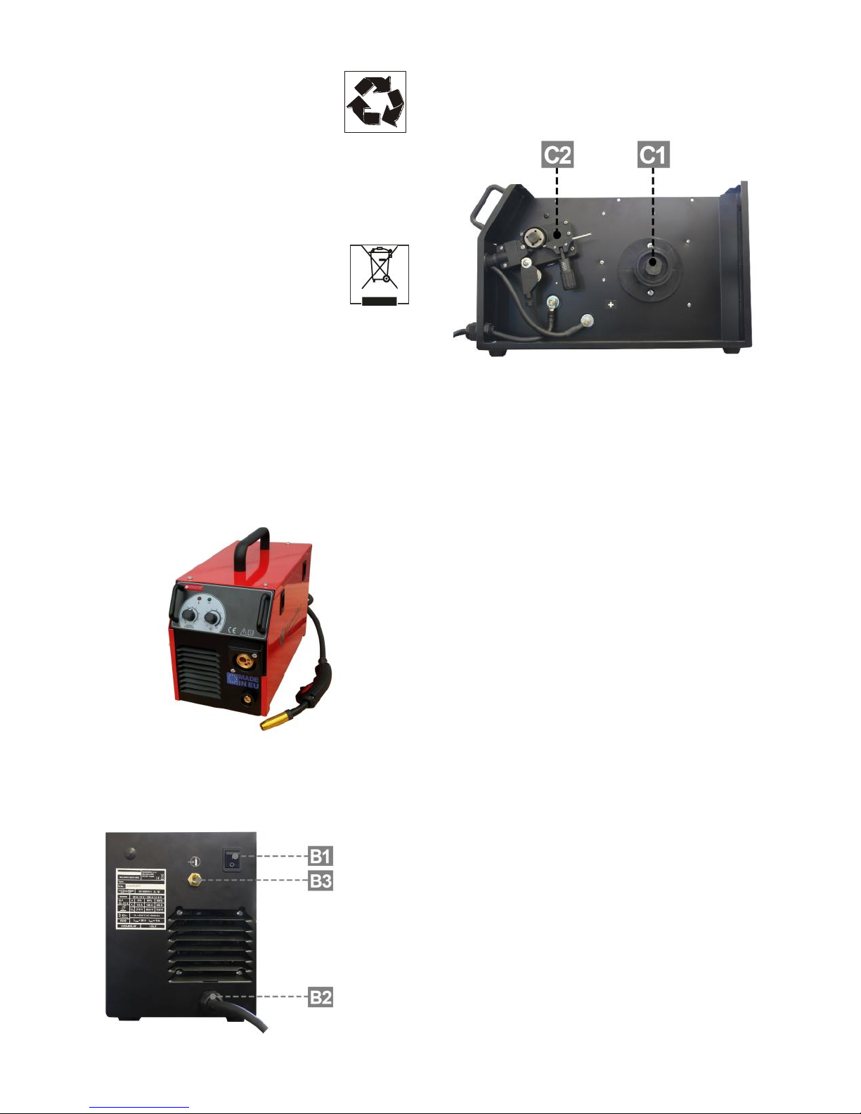
Picture 1 - Front view
Welding torch MW157 (fixed or connected to euro
connector – depending on the version of machine)
Earthing cable (fixed or connected to euro connector
– depending on the version of machine)
Picture 2 - Rear view
B1 - Main switch
B2 - Power supply cable - inlet
B3 - Inert gas inlet to the apparatus
Picture 3 - Side view
C1 - Wire reel coupling disc
C2 - Wire feed mechanism
PLACEMENT OF THE MACHINE
Place the apparatus on a level, compact and clean
surface. Protect the apparatus against rain and direct
sunshine. Allow for a sufficient space before and
beyond the apparatus for proper cooling. When
choosing the position of the machine placement, be
careful to prevent the machine from conducting
impurities and getting them inside (for example
flying particles from the grinding tool).
Cable connections
CONNECTING THE APPARATUS TO THE MAINS
2040 and 2050 apparatus meets the requirements of
Safety Class I, which means that all metal parts are
accessible without the necessity of removing a cover;
the parts are bonded to the protective earthing of
the mains. The apparatus may be connected only
with a mains cable provided with the plug and protective earthing contact. Switch off the apparatus
only by the use of the main switch on the apparatus.
Never use the mains plug for this purpose! The necessary protection parameters are shown in the
‘Specifications’ section.
The apparatus is supplied with the 16 A for the connection to 1x 230 V single-phase mains.
Only properly qualified person (in electrical engineering) may replace the power supply cable, if
necessary.
The relevant socket outlet should be protected by
fuses or automatic circuit breaker.
NOTE 1: Any extensions to the power cable must be
of a suitable diameter, and absolutely not of a smaller diameter than the special cable supplied with the
machine.
Page 8
- 8 -
NOTE 2: Owing to the connected load level, the
approval of the relevant electricity distributing company may be necessary for the connection of this
equipment to the public mains.
WELDING TORCH
The welding is used for supplying the welding wire,
inert gas and current to the welding place. Once the
torch pushbutton is pressed, the welding wire and
protective gas start to pass through the torch. The
arc is activated at the contact of the welding wire
with the welded material.
IMPORTANT NOTE: If you use a welding wire of
a different diameter than 0.8 mm, it will be necessary to exchange the drawing die on the torch for
a drawing die of suitable diameter.
EARTHING CABLE
Keep the earthing clamp clean so that its contact
with the welded material is complete. If possible,
place them directly to the welded part. The contact
area must be clean and as large as possible. If necessary, the area must be cleaned from paint and rust.
PROTECTIVE GAS AND CYLINDER INSTALLATION
For the protective shield in MIG/MAG welding, use
inert gases (argon, CO2, or argon-CO2 mixture). Make
sure that the pressure-reducing valve is of a suitable
type for the used gas.
Cylinder installation
Fix the gas cylinder properly and in the upright position, either in a special holder or trolley. Do not
forget to close the gas cylinder valve after completed
welding.
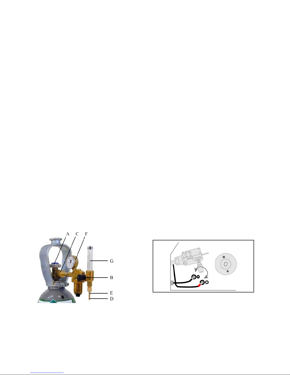
Picture 4
The following installation instructions are applicable
to the majority of pressure-reducing valve types:
1. Keep aside and open for a moment the cylinder
pressure-reducing valve “A” (Pic. 4). Impurities
or dirt, if any, will be blown away from the cylinder valve.
IMPORTANT NOTE: Be careful because of the
high gas pressure!
2. Turn the pressure controlling screw “B” of the
pressure-reducing valve until you feel the spring
compression.
3. Close the pressure-reducing valve.
4. Fit the pressure-reducing valve over the gasket
of the inlet connecting pipe onto the cylinder
and tighten cap nut “C” using a wrench.
5. Fit on the hose adapter “D” with the cap nut “E”
to the gas pipe and fasten with the hose clip.
6. Connect one end of the hose to the pressurereducing valve and the second end to the welding apparatus.
7. Tighten the cap nut with the hose at the pressure-reducing valve.
8. Slowly open the cylinder valve. The cylinder
pressure gauge “F” will indicate the pressure in
the cylinder.
NOTE: Do not consume the whole cylinder content. The cylinder should be replaced as soon as
the pressure drops down to 2 bars.
9. Open the valve of the pressure-reducing valve.
10. Press the torch pushbutton, while the apparatus
is switched on.
11. Turn the pressure controlling screw “B” until the
flow-meter “G” shows the required flow rate.
After the completion of the welding operation close
the cylinder valve. If not in service for a longer period, loosen the pressure controlling screw.
PREPARATIONS FOR WORK - REVERSING THE POLARITY
Some types of the welding wire require in welding
reversed polarity of the welding current. Check the
polarity recommended by the manufacturer indicated on the wire packaging.
Picture 5 - Reversing the polarity
1. Disconnect the apparatus from the mains.
2. Unscrew the two self-cutting screws fixing the
cover of the output terminals.
3. Loosen and unscrew the nuts fixing the output
cables. Note the correct sequence of the washers.
4. Swap the cables.
Page 9
- 9 -
5. Place the washers back, put on and tighten the
nuts.
6. Screw on the cover of the output terminals
back.
REPLACEMENT OF THE FEED ROLLER
The roller installed at the manufacturer’s place is
suitable for wire diameters of 0.6 - 0.8 mm. In
a thinner/thicker wire is to be used, the roller must
be replaced.
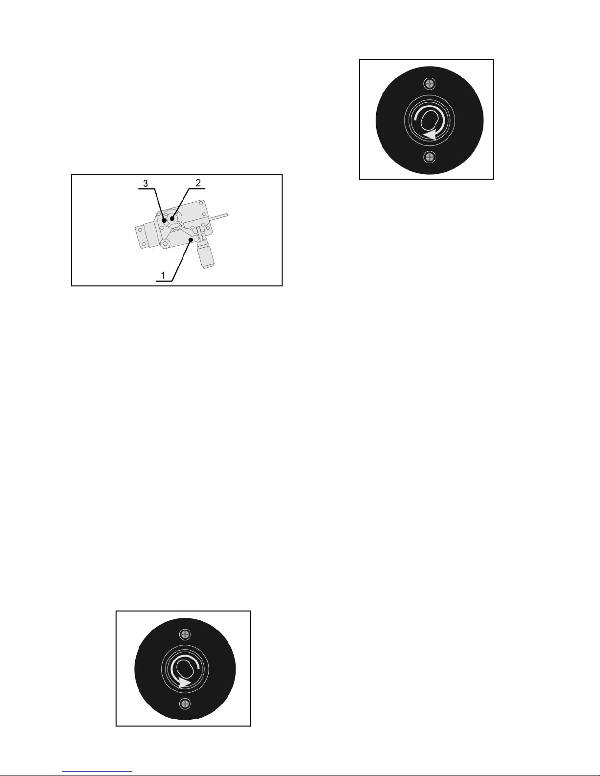
Picture 6 - Replacement of the feed roller
1. Swing away the pressing arm (Pic. 6, pos. 1).
2. Loosen by hand the grooved screw fixing the
feed roller (pos. 2).
3. Remove the feed roller from its shaft (pos. 3).
4. Turn around or replace the feed roller and fix it
to the original position.
5. Tighten the screw fixing the feed roller.
HOW TO INSTALL THE WIRE REEL
Open the side cover by pressing the plastic locks on
the apparatus. Set the lock of the wire reel carrier
into the “open” position and take the carrier apart.
Place the reel on the wire carrier so that the reel can
turn anticlockwise. Coils containing 5 kg of wire
(Ø200 mm) or 1 kg of wire (Ø100 mm) can be used.
Assemble the carrier again and secure it with the
lock of the wire reel carrier the “locked” position. Do
not forget to install the spring between the carrier
lock and reel adapter. For the wire feed, fix the roller
suitable for the relevant wire type and diameter. (As
the standard, rollers with “V” grooves and 0.6 - 0.8
mm wire diameters are installed).
Slide the reel with the wire on the carrier.
Open
Locked
Picture 7
LEADING-IN THE WIRE
Release the wire end from the reel but keep it
tightly for the whole period.
Straighten the wire end and cut it in a manner
making its leading-in to the wire feed easy.
Open the pressing roller.
Lead in the wire over the lead-in Bowden, feed
roller and torch Bowden.
Hold down the wire so it cannot slip out and
close the pressing roller. Make sure that the
wire is in the feed roller groove.
Set the thrust pressure of the pressing roller to
one half of the scale at the most. If the pressure
is too high, the wire will be deformed and small
shavings created on its surface. If the pressure is
too low, the wire will creep and the feed will not
be smooth.
In order to avoid any injury by pressing a part of the
human body during leading-in the wire into the
feed, close the wire feed cover before pressing the
torch pushbutton.
Press the torch pushbutton and wait until the wire is
moves out of the torch tip.
The wire lead-in rate can be controlled by the controlling element 1 (Pic. 8) on the front panel.
Before welding, apply the separation spray to the
space in the gas nozzle and current drawing die. By
this, the splashed metal particles will not stick to the
surface and the gas nozzle service life will be extended.
WARNING! During wire leading-in into the torch, do
not aim the torch against yourself or other persons!
The wire leaving the current tip is very sharp and
may cause injury. Do not place your fingers close to
the feed roller. While the torch pushbutton is
pressed, the roller rotates and can be cause of
squeezing.
IMPORTANT NOTE: While using the welding apparatus with a backup power supply or a mobile power
source (genset, etc.), it is necessary to use a goodquality source of a sufficient capacity and good control system.
Page 10
- 10 -
The power source capacity must be at least
6.5 kVA so that the apparatus can work in the maxi-
mum current range. If this principle is neglected,
there is a danger that the apparatus will not work
properly or at all while welding on the maximum
welding current or, as the case may be, damage to
the apparatus may result because of extensive drops
and increases in the supply voltage.
Controlling and indicating elements
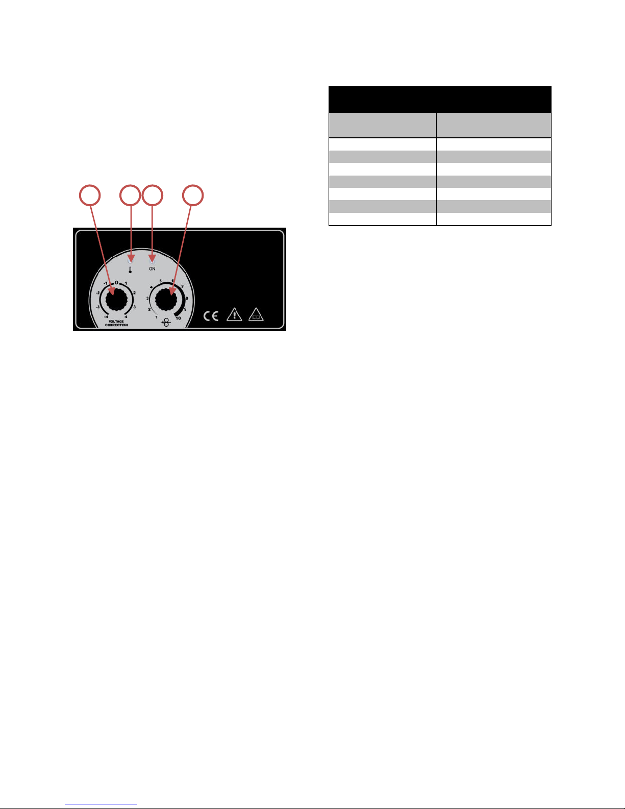
Picture 8
Position 1 Wire feed rate controller (output regu-
lator).
Position 2 Voltage correction regulator (arc
length regulator).
Position 3 Apparatus ‘ON’ indicator.
Position 4 Apparatus overheating indicator.
The welding output is adjusted by the controller
1 (Pic. 8) according to the welded material thickness. The controller 2 is used for the voltage correction (and it regulates the arc length at the same
time).
The control lamps inform about the turning the
machine on (3) and thermal protection activation (4).
Green light is on after switching on the apparatus.
If the apparatus is overheated or its supply voltage is
too low or too high, the welding process will be
automatically stopped and yellow light will be on.
Once the yellow control lamp is off, the apparatus is
prepared for the service again.
ADJUSTMENT OF THE WELDING OUTPUT
The welding output regulator adjusts, at the same
time, the output voltage and wire feed rate. At the
same time, both these parameters determine, for
which material thickness is the relevant setting suitable.
Table 2 shows reference values of welding parameter settings for various thicknesses of materials.
The Table is prepared for the basic settings in welding with the 0.8 mm dia wire. If the 0.6 dia wire is
used, then it will be necessary to set the welding
output slightly lower, while for 1.0 mm dia wire
slightly higher.
Setting of parameters according to the material
thickness (of a reference value only)
Material thickness
Feed rate potentiome-
ter position
0.5 1 0.75 3 1
4
1.5
6
2 7 3
8
4
10
Table 2
VOLTAGE CORRECTION SETTINGS
The voltage correction function influences the setting of the arc length and its temperature. If the
correction is shifted to the negative values, the arc
gets shorter and cooler, while the correction shifts to
positive values, longer and hotter.
Along with various combinations of wire diameters
and usage of various protective gas types, this voltage correction influences the arc properties. If the
arc is too convex, then it is short and cool. In such
case the correction to the positive values will be
necessary. If you need a shorter arc, e.g. to avoid
material penetrations in welding, a correction to the
negative values will be necessary.
IMPORTANT NOTE: If you start welding for the first
time, it will be suitable to set the voltage correction
regulator into the middle position!
WARNING! Any welding operations in places with
explosion/fire hazard are strictly forbidden!
Welding gaseous products might be harmful to human health! Provide for good ventilation during
welding operations!
Welding by the MIG/MAG method
a) Connect the gas hose from the gas cylinder
pressure-reducing valve to the B3 outlet (Pic. 2)
on the rear panel. Open the gas valve on the gas
cylinder.
b) Connect the apparatus to the mains.
c) Switch the B1 main switch on (Pic. 2).
d) Put the wire reel in its place; see “How to install
the wire reel”.
e) Lead-in the wire to the wire feed mechanism.
See “Leading-in the wire”.
Principle of MIG/MAG welding
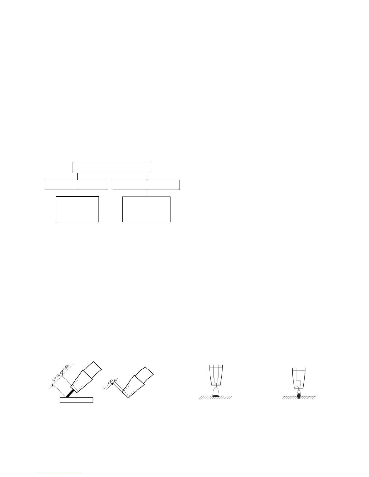
Welding wire is leading from the roller into the flow
drawing tie with the use of the feed. The Arc joins
thawing wire electrode with welding material. Weld-
1 3 4
2
Page 11
- 11 -
ing wire functions as a carrier of the arc and as the
source of additional material at the same time. Protective gas flows from the spacer who protects arc
and the whole weld against the effects of surrounding atmosphere (Pic. 9).
Picture 9
PROTECTIVE GASES
ADJUSTMENT OF WELDING PARAMETERS
For approximate adjustment of welding current and
voltage with MIG/MAG methods corresponds with
empirical relation U2 = 14 + 0.05 x I2. According to
this relation we can set required tension. During
adjustment of the tension, we must take into account with its decrease at loading by welding. Decrease of tension is approximately 4.8 V to 100 A.
Adjustment of welding current is done so that for
chosen welding tension set required welding current
by increasing or decreasing of the speed of wire feed
or we tune the tension so that the welding arc is
stable. For good quality of welds and optimal adjustment of welding current it is necessary to reach
the distance of drawing die from material of approximately 10x welding wire (Pic. 10). Dipping of
drawing die in gas tube should not extend 2 - 3 mm.
Picture 10
WELDING ARC TYPES
a/ Short welding arc
Welding with a very short welding arc means a low
voltage level of the welding arc and current in the
lower part of the range. The surface tension of the
bath facilitates the bringing-in of the drop into the
melted metal and - because of this - the new ignition
of the arc. This cycle is repeated over and over and
this causes permanent changing between the short
circuit connection and period of welding arc burning.
The melted metal flow is relatively “cool”, which
means that this method is suitable for welding of
thin metal sheets and for welding in forced positions.
The transition from the short arc to the spray arc
depends on the welding current, wire diameter and
gas mixture (Pic. 11).
b/ Transition welding arc
If it is allowed by the dimensions of welded materials, the welding operation should be conducted
under a higher consumable output (for economic
reasons), i.e. without exceeding the long or spray
arc. The transition welding arc means a slightly extended short welding arc. The material transition
takes place partly freely, partly within the shortcircuit connection. By this, the number of shortcircuit connections is reduced and the melting bath
flow is “hotter” than in the case of the so-called
short welding arc. This welding method is suitable
for middle thicknesses of materials and down-welds.
c/ Long welding arc
Large drops are formed in the long welding arc and
they penetrate the material by its weight. At this
method, accidental short-circuit connections and
consequent short-term current increases take place
causing the metal spraying after each ignition of the
welding arc. This welding method is suitable for
welding under CO2 shield and other gas mixtures
with the high CO2 content in the upper part of the
range. The method is not much suitable for welding
in forced positions (Pic. 11).
d/ Spray welding arc
The main feature of this welding method is the material transition in small droplets without any connection. The spray arc is to be adjusted, if welding is
to be done in inert gases or argon-rich mixtures in
the upper part of the range. The method is not suitable for welding in forced positions.
Long welding arc Short welding arc
Picture 11
HOLDING AND CONTROLLING THE WELDING TORCH
Protective gases
Inert gases – method MIG
Active gases – method MAG
Argon (Ar)
Helium (He)
Mixture He/Ar
Carbon dioxide
Mixed gases
Ar/CO2
AR/O2
Page 12
- 12 -
A B C
Picture 12
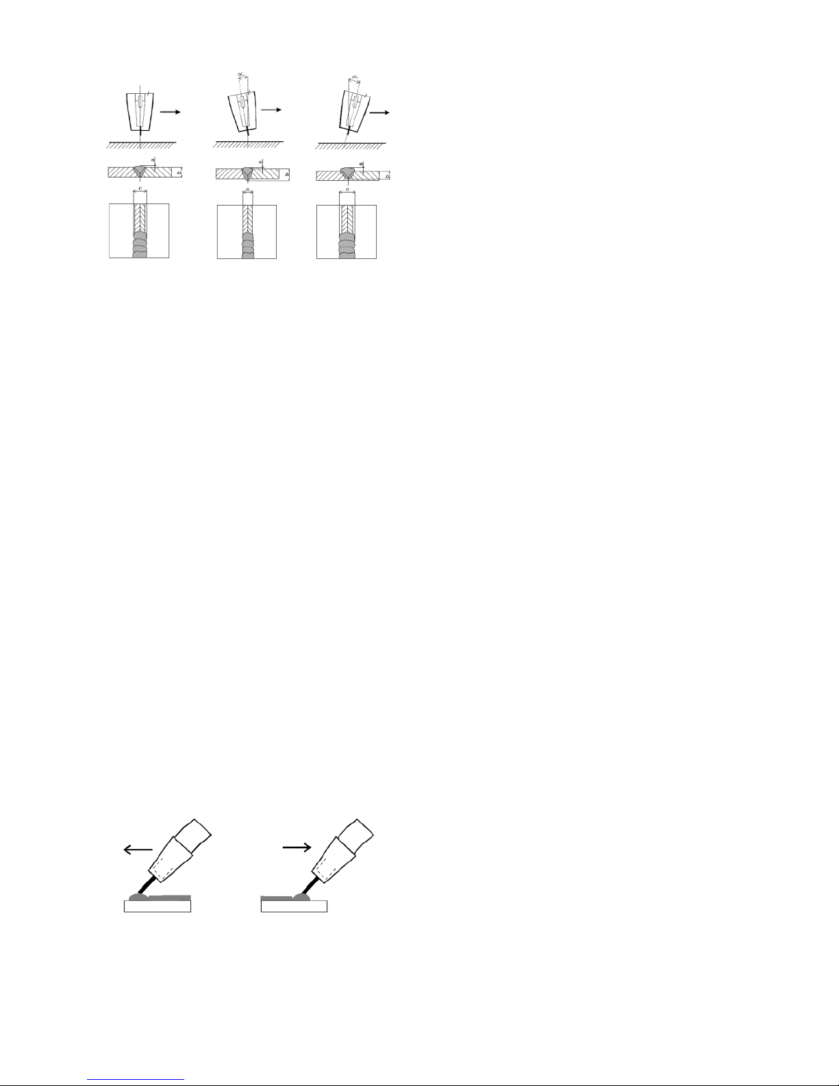
Gas shielded arc welding can be conducted, if the
relevant parameters are suitably selected, in all
positions (horizontal, vertical, overhead, vertical-up
or vertical-down and across, at the same time in
these positions). In horizontal or vertical positions,
the usual gripping of the torch is in the angle of 30°.
In the case of more thick layers, the welding process
is performed by light drawing. The most suitable grip
on the torch for the optimum coverage of the weld
place by shielding gas is vertical (neutral) positioning
of the torch (Pic. 11 A). However, in this position it is
difficult to watch the welded place (it is hidden behind the gas nozzle). For this reason, the torch
should be slightly tilted (Pic. 11 BC). On the other
hand, if the torch tilt is excessively off this position,
there is a danger of sucking air into the shield gas,
which might negatively influence the weld quality.
WELDING BY PRESSING AND DRAWING
Slight moves with “pressing” are used in vertical-up
welding and horizontal overhead welding (Pic. 13).
Only in vertical-down welding the torch is gripped in
the neutral or slightly “drawing” position. The vertical-down welding is used mostly for thin metal
sheets, because there is a risk of a poor connection
with thick sheets; the molten metal tends to pour
down along the connection and “overtake” the weld,
particularly when the molten metal is too liquid
because of high voltage. Such method requires a
high degree of expertise and experience (Pic. 14).
Picture 13 Picture 14
Maintenance
WARNING: Before carrying out any inspection of the
inside of the generator, disconnect the system from
the supply.
In planning of maintenance procedures, the level
and circumstances of the apparatus usage must be
taken into account. Careful handling and preventive
maintenance helps to avoid unnecessary failures and
defects.
If required by the apparatus working conditions,
the inspection and maintenance intervals must be
shortened. If the apparatus is used in a very dusty
environment (conduction dust), then intervals will
be as short as twice a month.
REGULAR MAINTENANCE AND INSPECTIONS
Conduct the inspections according to the relevant
Czech Standard (EN 60974-4.). Before any use of the
apparatus, check the conditions of the welding and
power supply cables. Do not use damaged cables!
Visual inspections include:
1. Torch, welding current return clamp
2. Power supply network
3. Welding circuit
4. Covers
5. Controlling and indicating elements
6. Apparatus condition in general
EVERY HALF A YEAR
Remove the plug from the socket outlet and wait for
two minutes (to allow for discharging of capacitors
inside the apparatus). Then remove the cover of the
apparatus. Clean all internal power supply connections from dust and dirt. Where they are loose,
tighten them.
Clean all internal parts of the apparatus from dust
and dirt using a soft brush of vacuum cleaner.
NOTE: Be careful when using compressed air in order
to not damage any parts.
Never use any solvents or diluents (such as acetone,
etc.); plastic material and front panel lettering could
be damaged in such procedures.
Only sufficiently qualified technicians (electrical
engineers) may repair the apparatus.
SPARE PARTS
Original spare parts have been specially designed for
our equipment. The use of non-original spare parts
may cause variations in performance or reduce the
foreseen level of safety. We decline all responsibility
for the use of non-original spare parts.
THE GENERATOR
As these systems are completely static, proceed as
follows:
Page 13

- 13 -
Periodic removal of accumulated dirt and dust
from the inside of the generator, using compressed air. Do not aim the air jet directly onto
the electrical components, in order to avoid
damaging them.
Make periodical inspections in order to individ-
uate worn cables or loose connections that are
the cause of overheating.
Periodical revision inspection of the machines
has to be done once in a half of year by an authorised staff in accord with EN 331500, 1990
and EN 056030, 1993.
WIRE FEED
Great attention has to be paid to the feeding mechanism, especially to the sheaves and the space
around them. During the wire feeding, copper coating peels off and small fillings fall off, which are
either brought into the spring or pollute the inner
space of feeding mechanism. Regularly remove and
store up dirt and dust from the inner part of wire
store and feeding mechanism.
WELDING TORCH
The welding torch has to be regularly maintained
and worn-out parts have to be exchanged on time.
The most stressed parts are the flow drawing die,
the gas tube, the pipe of the torch, the spring for
leading the wire, the coaxial cable and the button of
the torch.
The flow drawing leads welding current into wire and
at the same time wire is directed to the point of
welding. It has service life from 3 to 20 welding
hours (according to the producer), which depends on
the quality of material of drawing die (Cu or CuCr),
the quality and surface finish of wire, welding parameters and service. The exchange of drawing die is
recommended after the worning-out of drawing die
hole to 1.5 multiple of wire diameter. After each
installing and exchange it is recommended to spray
the drawing die and its thread with separating spray.
The gas tube leads gas which protects the arc and
molten pool. The spatter of metal clogs the tube and
it is necessary to clean it regularly to secure good and
uniform flow of gas and to avoid short-circuit between the drawing die and the tube. A short-circuit
can make damage to the rectifier! The speed of clogging the tube depends particularly on good adjustment of welding process.
The spatter of metal is easily removed after spraying
the gas tube with separating spray.
After these precautions, spatter falls out partially,
though it is necessary to remove it every 10 - 20
minutes from the space between the tube and drawing die with non-metallic rod by mild pounding.
According to the current and rate of work you need
to take off the gas tube twice of 5 times during the
shift and to clear it thoroughly, including channels of
the spacer, which serve as gas inlet. You are not
allowed to pound with the gas tube since its insulating compound can be damaged.
The spacer is also exposed to the effects of the spatter and heat stress. Its service life is 30 - 120 welding
hours (according to the producer).
Time intervals of changing the springs depend on the
wire purity and maintenance of the feeding mechanism and adjustment of the trust of feed sheaves.
Once a week it has to be cleaned with trichloroethylene and blown through with compressive air. In the
case of high working-out or its clogging the spring
has to be exchanged.
The pointing out of any difficulties
and their elimination
The supply line is attributed with the cause of the
most common difficulties. In the case of breakdown,
proceed as follows:
1. Check the value of the supply voltage
2. Check that the power cable is perfectly con-
nected to the plug and the supply switch
3. Check that the power fuses are not burned out
or loose
4. Check whether the following are defective:
The switch that supplies the machine
The plug socket in the wall
The generator switch
NOTE: Given the required technical skills necessary
for the repair of the generator, in case of breakdown
we advise you to contact skilled personnel or our
technical service department.
Side cover assembly and disassembly procedure
Before removing the side covers, always discon-
nect the power supply cable plug from the
mains!
Remove the side cover partially covering the
wire feed mechanism.
Unscrew four screws of the right side cover,
then four upper screws and two screws fixing
the cover inside the space of the wire feed
mechanism.
In the assembly of the apparatus, proceed in the
opposite sequence of steps.
Page 14
- 14 -
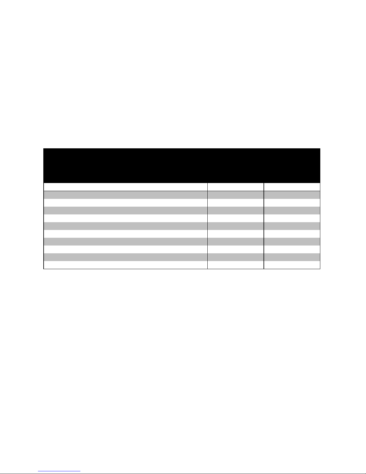
Orientační tabulka nastavení rychlosti podávání drátu
Orientačná tabuľka nastavení rýchlosti podávania drôtu
Table for setting of wire feed rate (for reference only)
Tabelle zur Orientierung mit Einstellungen der Geschwindigkeit des
Drahtvorschubs
Orientacyjna tabela nastawienia prędkości podawania drutu
Pozice voliče rychlosti posuvu drátu
Pozícia voliča rýchlosti posuvu drôtu
Position of the wire feed rate selector
Position des Wahlschalters für Geschwindigkeit des Drahtvorschubs
Pozycja pokrętła regulacji prędkości posuwu drutu
Rychlost podávání drátu [m/min]
Rýchlosť podávania drôtu [m/min]
Wire feed rate [m/min]
Geschwindigkeit des Drahtvorschubs [m/min]
Prędkość podawania drutu [m/min]
2040
2080
1
1,0
1,0
2
1,7
1,8 3 3,2
3,4
4
4,0
4,3
5
4,9
5,3 6 5,5
6,4
7
6,7
7,2
8
8,5
9,4
9
9,8
10,6
10
11,0
12,0
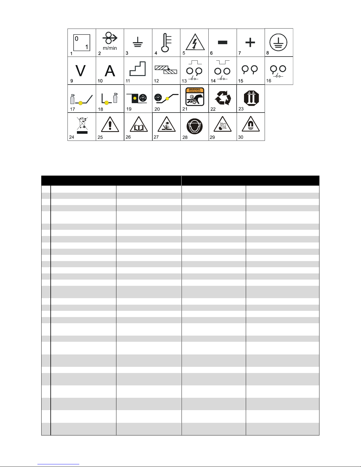
Použité grafické symboly / Key to graphic symbols / Farbzeichenerklärung
Zastosowane symbole graficzne
Page 15
- 15 -
CZ - popis
SK - popis
EN - description
DE - Beschreibung
1
Hlavní vypínač
Hlavný vypínač
Main switch
Hauptschalter
2
Rychlost posuvu drátu
Rýchlosť posuvu drôtu
Wire speed
Drahtvorschubgeschwindigkeit
3
Uzemnění
Uzemnenie
Ground
Erdung
4
Kontrolka tepelné ochrany
Kontrolka tepelnej ochrany
Thermo control
Signallampe Wärmeschutz
5
Výstraha - riziko úrazu el.
proudem
Výstraha - riziko úrazu el.
prúdom
Warning risk of electric shock
Warnung Risikounfall durch el.
Strom
6
Mínus pól na svorce
Mínus pól na svorke
Minus polarity
Minuspol auf der Klemme
7
Plus pól na svorce
Plus pól na svorke
Plus polarity
Pluspol auf der Klemme
8
Ochrana zemněním
Ochrana zemnením
Ground protection
Erdungsschutz
9
Svařovací napětí
Zváracie napätie
Welding voltage
Schweißspannung
10
Svařovací proud
Zvárací prúd
Welding current
Schweißstrom
11
Přepínač napětí
Prepínač napätia
Welding current switch
Spannungsumschalter
12
Síla svařovaného materiálu
Sila zváraného materiálu
Material thickness
Dicke des Schweißmaterials
13
Bodové svařování
Bodové zváranie
Spotting welding
Punktschweißen
14
Pulsové svařování
Pulzové zváranie
Pulse mode
Pulsschweißen
15
Plynulé svařování
Plynulé zváranie
Continue welding
Kontinuierliches Schweißen
16
Svařování ve čtyřtaktním
režimu
Zváranie vo štvortaktnom
režime
Four cycle welding
Schweißen im Viertakt - Betrieb
17
Předfuk plynu
Predfuk plynu
Gas fore-blow
Gas -Vorströmen
18
Dofuk plynu
Dofuk plynu
Gas after-blow
Gas - Nachströmen
19
Dohoření drátu
Dohorenie drôtu
Burning out of wire
Drahtverlöschen
20
Soft start
Soft štart
Soft start
Soft start
21
Pozor, točící se soukolí
Pozor, točiace sa súkolie
Attention, revolving gearing
Vorsicht, rotierendes
Zahnradgetriebe
22
Suroviny a odpad
Suroviny a odpad
Materials and disposal
Rohstoffe und Abfälle
23
Manipulace a uskladnění
stlačených plynů
Manipulácia a uskladnenie
stlačených plynov
Handling and stocking compressed gases
Manipulation und Lagerung mit
Druckgas
24
Likvidace použitého zařízení
Likvidácia použitého zariadenia
Disposal of used machinery
Entsorgung der benutzten
Einrichtung
25
Pozor nebezpečí!
Pozor nebezpečenstvo!
Caution danger!
Vorsicht Gefahr
26
Seznamte se s návodem k
obsluze
Zoznámte sa s návodom k
obsluhe
Read service instructions
Lernen Sie die
Bedienungsanleitung kennen
27
Zplodiny a plyny při svařování bezpečnostní pokyny
Splodiny a plyny pri zváraní bezpečnostné pokyny
Safety regarding welding
fumes and gas
Produkte und Gäse beim Schweißen
28
Ochrana před zářením,
popáleninami a hlukem
Ochrana pred žiarením,
popáleninami a hlukom
Protection from radiation,
burns and noise
Schutz vor Strahlung,
Brandwunden und Lärm
29
Zabránění požáru a exploze
Zabránenie požiaru a explózie
Avoidance of flames and
explosions
Brandverhütung und
Explosionverhütung
30
Nebezpečí spojené
s elektromagnetickým polem
Nebezpečenstvo spojené
s elektromagnetickým polom
Risks due electromagnetic
fields
Die mit elmagn. Strahlung
verbundene Gefahr
Page 16
- 16 -
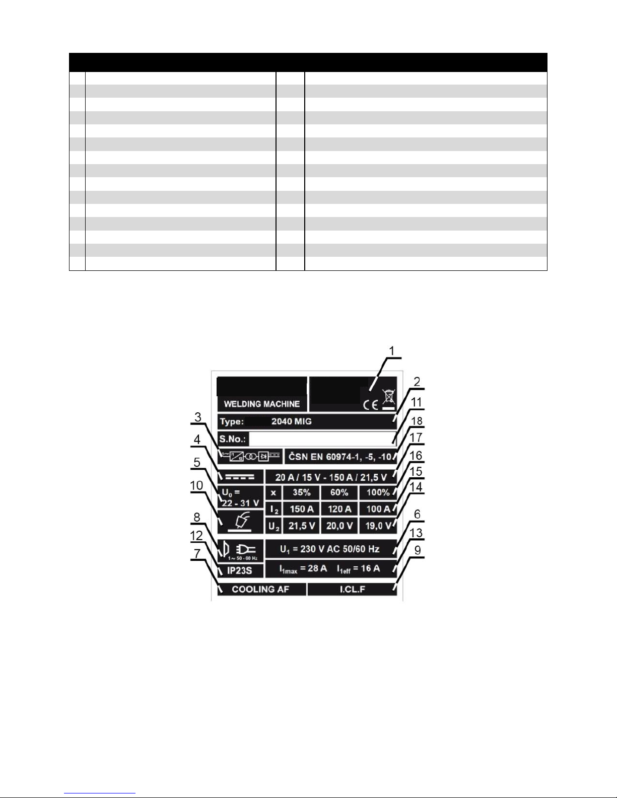
Grafické symboly na výrobním štítku / Grafické symboly na výrobnom štítku
Graphic symbols on the production plate / Erklärung der Sinnbilder am
Typenschild / Symbole graficzne na tabliczce produkcyjnej
PL - opis
1
Wyłącznik główny
16
Spawanie w reżimie czterosuwu
2
Szybkość posuwu drutu
17
Wstupne dmuchanie gazu
3
Uziemienie
18
Koncowe dmuchanie gazu
4
Lampka kontrolna ochrony cieplnej
19
Dopalanie drutu
5
Niebezpieczeństwo, wysokie napięcie
20
Soft Start
6
Biegun ujemny na listwie
21
Uwaga, mechanizm kołowy się obraca
7
Biegun dodatni na listwie
22
Surowce i odpad
8
Ochrona uziemieniem
23
Manipulacja i przechowywanie gazów sprężonych
9
Napięcie spawalnicze
24
Utylizacja zużytego urządzenia
10
Prąd spawalniczy
25
Uwaga niebezpieczeństwo!
11
Przełącznik napięcia
26
Proszę zapoznać się z Instrukcją Obsługi
12
Grubość materiału spawalnic-zego
27
Czynniki szkodliwe i gazy powstające w trakcie spawania
13
Spawanie punktowe
28
Ochrona przed napromieniowaniem, oparzeniami i hałasem
14
Spawanie impulsowe
29
Unikanie pożaru i wybuchu
15
Spawanie ciągłe
30
Niebezpieczeństwo związane z polem elektromagnetycznym
Page 17
- 17 -
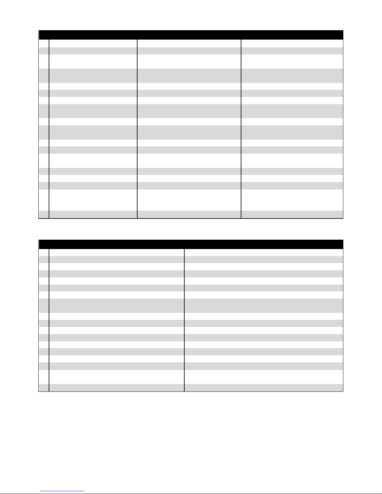
CZ - popis
SK - popis
EN - description
1
Název a adresa výrobce
Názov a adresa výrobca
Name and address of the manufacturer
2
Typ stroje
Typ stroja
Type of machine
3
Značka zdroje svařovacího proudu
(jednofázový invertor)
Značka zdroja zváracieho prúdu
jednofázový invertor
Symbol for the welding current unit
(single-phase inverter)
4
Značka svařovacího proudu
(stejnosměrný proud)
Značka zváracieho prúdu jednosmerný
prúd
Symbol for the welding current (direct
current)
5
Jmenovité napětí naprázdno
Menovité napätie naprázdno
Rated voltage
6
Jmenovité napájecí napětí
Menovité napájacie napätie
Supply voltage
7
Chlazení ventilátorem
Chladenie ventilátorom
Fan-cooled
8
Napájecí obvod, počet fází, střídavý
proud, frekvence
Napájací obvod, počet fází, striedavý
prúd, frekvencia
Power supply circuit, number of phases,
alternating current, frequency
9
Tepelná třída izolace
Trieda izolácie
Insulation class
10
Stroj pro svařování metodou
MIG/MAG
Stroj pre zváranie metódou MIG/MAG
Apparatus for MIG/MAG welding method
11
Výrobní číslo
Výrobné číslo
Serial number
12
Stupeň ochrany krytem
Stupeň ochrany krytom
IP Code Rating
13
Jmenovitý maximální a efektivní
napájecí proud
Menovitý maximálny a efektívny napájací
prúd
Nominal maximum and effective supply
current
14
Normalizované pracovní napětí
Normalizované pracovné napätie
Standardized operating voltage
15
Jmenovitý svařovací proud
Menovitý zvárací prúd
Welding current
16
Zatěžovatel
Zaťažovateľ
Load factor
17
Rozsah výstupu (minimální a
maximální svařovací proud a
odpovídající pracovní napětí)
Rozsah výstupu (minimálny a maximálny
zvárací prúd a odpovedajúce pracovné
napätie)
Output range (min. and max. welding
current and relevant operating voltage)
18
Normy
Normy
Standards
DE - Beschreibung
PL - opis
1
Name und Adresse des Herstellers
Nazwa i adres producenta
2
Maschinentyp
Rodzaj maszyny
3
Symbol Schweißstromquelle (Einphaseninverter)
Jednofazowy invertor
4
Symbol Schweißstrom (Gleichstrom)
prąd stały
5
Lastnennspannung
Nominalne napięcie na biegu jałowym
6
Rated Netzteil
Nominalne napięcie zasilania
7
Ventilatorkühlung
Chłodzenie wentylatorem
8
Netzteil (Speisestromkreis) Anzahl der Phasen,
Wechselstrom, Frequenz
Obwód zasilania, Ilość fazy, frekwencja
9
Isolierungsklasse
Klasa izolacji
10
Schweißgerät für die Methode MIG/MAG
Maszyna do spawaniw atmosferze ochronnej MIG/MAG
11
Produktionsnummer
Numer produkcyjny
12
Schutzart
Stopień ochrony
13
Maximaler und effektiver Nennversorgungsstrom
Maksymalny i efektywny nominalny prąd zasilania
14
Normarbeitsspannung
Nominalne napięcie
15
Rated Schweißstrom
Nominalny prąd spawalniczy
16
Belastungsfaktor
Czas obciążenia
17
Bereich des Ausgangs (minimaler und maximaler
Schweißstrom und entsprechende Arbeitsspannung)
Zakres mocy (min. i max. prąd spawalniczy i odpowiadające
napięcie pracy
18
Norm
Normy
Page 18
- 18 -
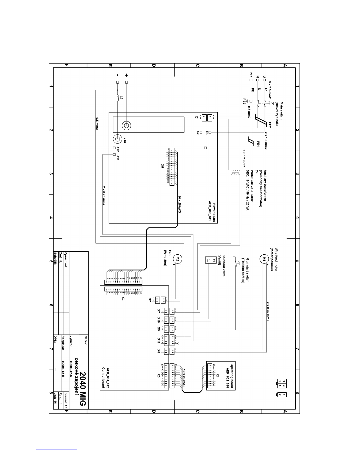
Elektrotechnické schéma / Elektrotechnické schéma
Electrical diagram / Schaltplan / Schemat elektrotechniczny
Page 19
- 19 -
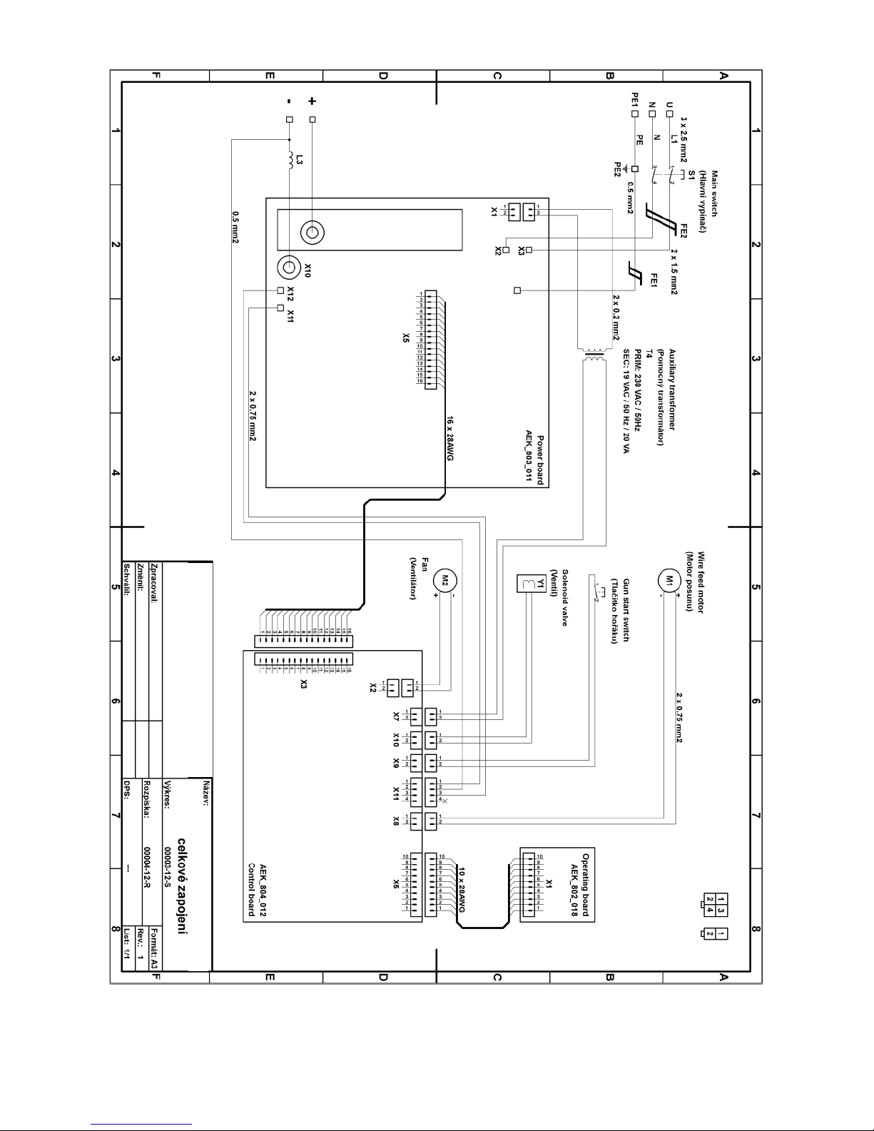
2080
Page 20
- 20 -
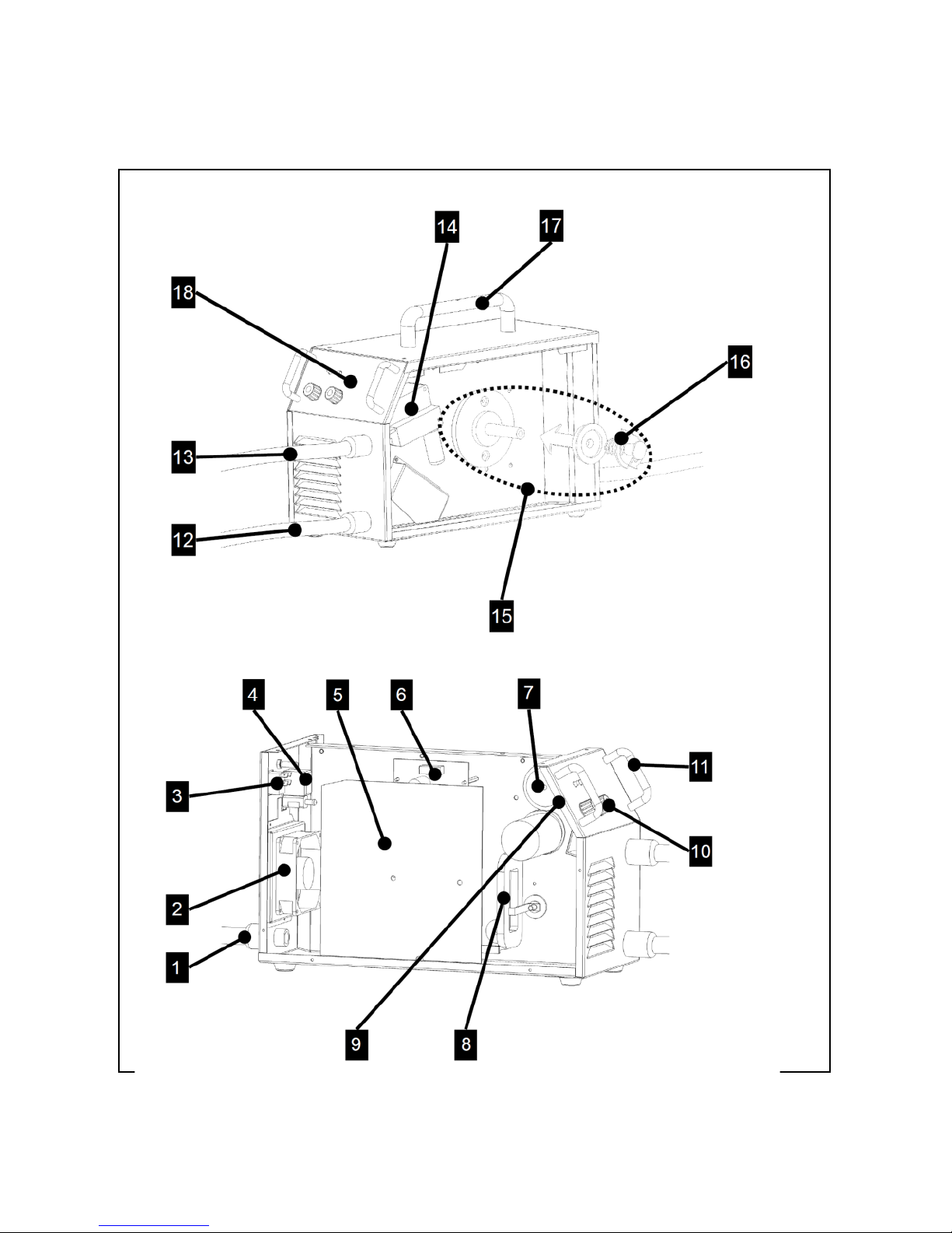
Seznam náhradních dílů / Zoznam náhradných dielov
List of spare parts / Ersatzteilliste / Lista części zamiennych
Page 21
- 21 -
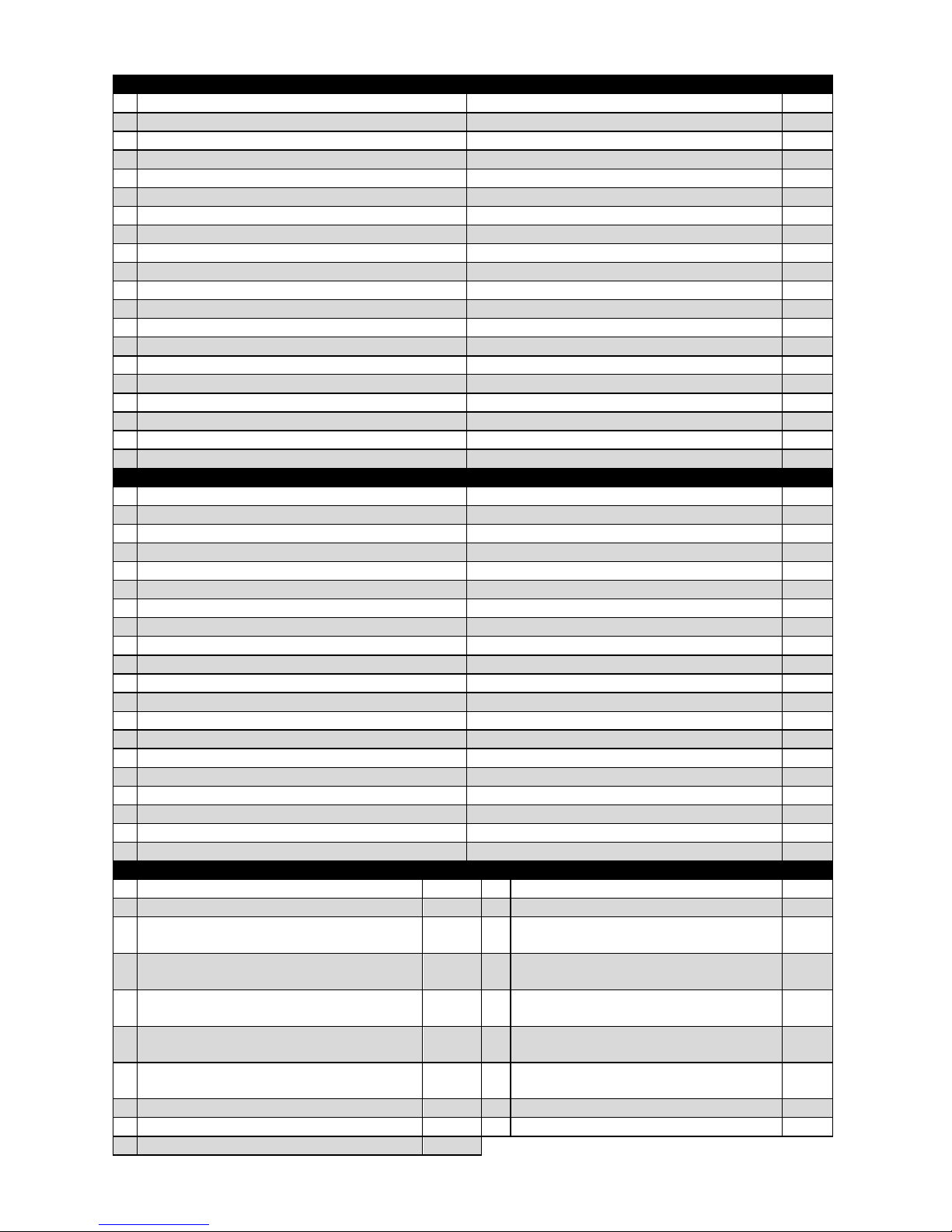
CZ - náhradní díly
SK - náhradné diely
No. 1 kabel přívodní 2040 MIG
prívodný kábel 2040 MIG
11390
2
ventilátor 2040 komplet
ventilátor 2040 komplet
11371
3
vypínač 2x16A
vypínač 2x16A
30452
4
ventil plynový 24V s filtrem DC
ventil plynový 24V s filtrom DC
32717
5
plošný spoj AEK-803-011 - výkonová (2040)
plošný spoj AEK-803-011 – výkonové (2040)
11299
5
plošný spoj AEK-803-012 - výkonová (2050)
plošný spoj AEK-803-012 – výkonové (2050)
11848
6
plošný spoj AEK-804-012 - řídící
plošný spoj AEK-804-012 - riadiace
11298
7
ovládací transformátor 2040 MIG - komplet
ovládací transformátor 2040 MIG - komplet
11389
8
tlumivka 2040 MIG
tlmivka 2040MIG
11318
9
plošný spoj AEK-802-018-ovládací
plošný spoj AEK 802-018 ovládací
11300
10
knoflík přístrojový HF
spínač prístrojový HF
30860
11
madlo kovové černé
madlo kovové čierne
30731
12
kabel zemnící 2040 MIG
kábel zemniaci 2040 MIG
11375
13
hořák MB 15 AG (varianta s pevným hořákem)
horák MB 15 AG (varianta s pevným horákom)
11392
14
posuv 2040 MIG (varianta s pevným hořákem)
posuv 2040 MIG (varianta s pevným horákom)
11370
14
Posuv 2040 MIG s euro-konektorem komplet
Posuv 2040 MIG s euro-konektorom komplet
30735
15
držák cívky plast 2040 MIG
držiak cievky plast 2040 MIG
30723
16
pružina tlačná k držáku cívky plast
pružina prítlačná k držiaku cievky plast
21040
17
madlo 20 cm plast
madlo 20 cm plast
30722
18
samolepka čelní panel 2040/2050 MIG
samolepka čelná panel 2040/2050 MIG
33160
EN - spare parts
DE - Ersatzteile
No.
1
Supply cable for 2040 MIG
Stromversorgungskabel 2040 MIG
11390
2
Fan for 2040 - complete
Ventilator 2040 MIG - komplett
11371
3
2×16A switch
Schalter 2 x 16 A
30452
4
Gas valve - 24V with DC filter
Gasventil 24 V mit Filter DC
32717
5
Printed circuit AEK-803-011 - power (2040)
Leiterplatte AEK-803-011 - Leistungsplatte(2040)
11299
5
Printed circuit AEK-803-012 - power (2050)
Leiterplatte AEK-803-012 - Leistungsplatte(2050)
11848
6
Printed circuit AEK-804-012 - controlling
Leiterplatte AEK-804-012 - Steuerplatine
11298
7
Control transformer for 2040 MIG - complete
Steuertransformator 2040 MIG - komplett
11389
8
Impedance coil for 2040 MIG
Drosselspule 2040 MIG
11318
9
Printed circuit AEK-802-018-ovládací
Leiterplatte AEK-802-018 - Steuerplatine
11300
10
Instrument knob HF
Geräteknopf HF
30860
11
Black metal grab handle
Metallgriff schwarz
30731
12
Earthing cable for 2040 MIG
Erdungskabel 2040 MIG
11375
13
Torch for MB 15 AG (version with fixed torch)
Brenner MB 15 AG
11392
14
Feed mechanisms for 2040 MIG (fixed torch version)
Drahtzuschub 2040 MIG (fest Brenner Variante)
11370
14
Feed mechanisms for 2040MIG with euroconnector
Drahtzuschub 2040 MIG Komplet mit Eurostecker
30735
15
Reel plastic holder for 2040 MIG
Kunststoffhalter für Spule 2040 MIG
30723
16
Compression spring for the reel plastic holder
Druckfeder zum Kunststoffhalter für Spule
21040
17
20 cm plastic grab handle
Griff 20 cm Kunststoff
30722
18
Front panel sticker for 2040/2050 MIG
Aufkleber vordere Blende 2040/2050 MIG
33160
PL - części zamienne
Nr. 1 kabel zasilający 2040 MIG
11390
11
uchwyt metalowy czarny
30731
2
wentylator 2040 komplet
11371
12
kabel masy 2040 MIG
11375
3
wyłącznik 2x16A
30452
13
palnik MB 15 AG (wariant z palnikiem
stałym)
11392
4
zawór gazowy 24V z filtrem DC
32717
14
posuw 2040 MIG (wariant z palnikiem
stałym)
11370
5
płytka drukowana AEK-803-011 - siłowa
(2040)
11299
14
Posuw 2040 MIG z eurokonektorem
komplet
30735
5
płytka drukowana AEK-803-012 - siłowa
(2080)
11848
15
uchwyt szpuli tworzywo 2040 MIG
30723
6
płytka drukowana AEK-804-012 - sterująca
11298
16
sprężyna tłoczna do uchwytu szpuli
tworzywo
21040
7
transformator 2040 MIG - komplet
11389
17
uchwyt 20 cm tworzywo
30722
8
dławik 2040 MIG
11318
18
nalepka panel czołowy 2040/2050 MIG
33160
9
płytka drukowana AEK-802-018-sterująca
11300
Page 22
- 22 -
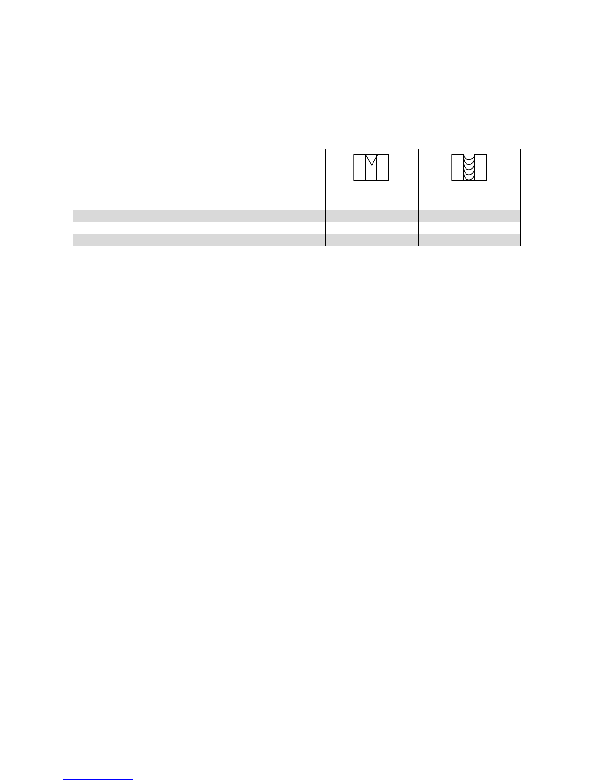
Náhradní díly a seznam kladek
Náhradné diely a zoznam kladiek
Spare parts and list of pulleys
Ersatzteile und Verzeichnis der Rollen
Części zamienne i wykaz rolek
Typ kladky / Type of roll
Vnitřní/vnější průměr kladky 10/30 mm
Inner/outer diameter of roll 10/30 mm
Innen/Aussen- durchmesser der Rolle 10/30 mm
Typ rolki - Średnica wewnętrzna/zewnętrzna rolki 10/30 mm
Ocel, nerez - Fe
Trubička - Tube wire
Průměr drátu / Średnica drutu / Ø of wire 0,6 - 0,8
33109 - 0,6/0,8
-
Průměr drátu / Średnica drutu / Ø of wire 0,8 - 1,0
33125 - 0,8/1,0
33171 - 0,9/1,0
Průměr drátu / Średnica drutu / Ø of wire 1,0 - 1,2
33164 – 1,0/1,2
33176 - 1,0/1,2
CZ - Příručka pro odstranění závad
UPOZORNĚNÍ: stroj mohou opravovat jen kvalifikovaní a příslušně vyškolení pracovníci!
ŘEŠENÍ PROBLÉMŮ
Drát se nepohybuje nebo se zamotává v podavači drátu
Opotřebené podávací kladky, zanesené vedení drátu, nebo špatný proudový průvlak.
Zkontrolujte podávací kladku, jestli není příliš těsná nebo volná.
Zkontrolujte podávací kladku, jestli není příliš opotřebovaná.
Zkontrolujte, jestli není zanesené vedení drátu.
Zkontrolujte, jestli není těsný otvor v proudovém průvlaku, nebo jestli není průvlak uvolněný.
Indikátor zapnutí stroje na čelním panelu nesvítí při zapnutí hlavního vypínače.
Stroj nemá napájecí napětí
Zkontrolujte napájecí napětí pojistky v napájecím obvodu.
Zkontrolujte napájecí napětí na kabelu a na zásuvce.
Stroj špatně svařuje:
Svařování je ovlivněno několika faktory
Zkontrolujte, jestli je podávání drátu pravidelné
Nevhodně nastavený svařovací výkon stroje, nebo korekce napětí
Zkontrolujte dokonalé uchycení zemnící svěrky, zda je zemnící bod čistý a zda není poškozený zemnící
kabel
Zkontrolujte, zda z hubice svařovacího hořáku vychází ochranný plyn
Napájecí napětí je příliš malé, nebo příliš velké
Svítí žlutý indikátor přehřátí stroje
Stroj je přehřátý
Zkontrolujte, zda nic nebrání volnému průchodu chladícího vzduchu strojem
Došlo k překročení zatěžovatele stroje; počkejte, až indikátor přehřátí zhasne
Napájecí napětí je příliš nízké nebo příliš vysoké
Page 23

- 23 -
SK - Príručka pre odstránení závad
UPOZORNENIE: stroj môžu opravovať iba kvalifikovaný a príslušne vyškolení pracovníci!
RIEŠENIE PROBLÉMOV
Drôt sa nepohybuje alebo sa zamotáva v podávači drôtu.
Opotrebené podávacie kladky, zanesené vedenie drôtu alebo špatný prúdový prievlak.
Skontrolujte podávaciu kladku, či nie je príliš tesná alebo voľná.
Či nie je príliš opotrebovaná.
Či nie je zanesené vedenie drôtu.
Či nie je tesný otvor v prúdovom prievlaku alebo či nie je prievlak uvoľnený.
Indikátor zapnutia stroja na čelnom panely nesvieti pri zapnutí hlavného vypínača.
Stroj nemá napájacie napätie.
skontrolujte napájacie poistky v napájacom obvode.
Skontrolujte napájacie napätie na kábli a na zásuvke.
Stroj špatne zvára:
Zváranie je ovplyvnené niekoľkými faktormi.
Skontrolujte či je podávanie drôtu pravidelné.
Nevhodne nastavený zvárací výkon stroja alebo korekcia napätia.
Skontrolujte dokonalé uchytenie zemniacej svorky, či je zemniaci bod čistý a nie je poškodený zemniací
kábel.
Skontrolujte či z hubice zváracieho horáka vychádza ochranný plyn.
Napájacie napätie je príliš malé alebo príliš veľké.
Svieti žltý indikátor prehriatia stroja:
Stroj je prehriaty.
Skontrolujte, či nič nebráni voľnému priechodu chladiaceho vzduchu strojom.
Došlo k prekročeniu zaťažovateľa stroja, počkajte pokým indikátor prehriatia zhasne.
Napájacie napätie je príliš nízke alebo príliš vysoké.
EN - Troubleshooting and repair guide
IMPORTANT NOTE: Only qualified and properly trained persons may repair the apparatus.
PROBLEM SOLVING
Problem: The wire does not move or is tangled in the wire feed mechanism
Probable cause: Worn feed rollers, wire guide is clogged or current drawing die is defective
Check, if the feed roller is not too tight or too loosen condition
Check, if the feed roller is not worn
Check, if the wire guide is not clogged
Check, if the opening in the current drawing die is not too tight or if the die is not loose
Problem: On the front panel, the control lamp for the apparatus ‘ON’ is not on at switching the apparatus on.
Probable cause: No supply voltage
Check the fuse supply voltage in the power supply circuit
Check the supply voltage on the cable and socket
Problem: Poor welding
Probable cause: Welding process may be influenced by several effects
Check for the regular wire feed
Unsuitably adjusted welding output or voltage correction
Check for proper gripping of the earthing clamp, check for earthing point cleanliness or damaged
earthing cable
Page 24

- 24 -
Check, whether the shield gas comes out of the torch nozzle
Too low or too high supply voltage
Problem: Yellow control lamp is on
Probable cause: Overheated apparatus
Check, if cooling air can pass freely through the apparatus
The apparatus (load factor) is overloaded; wait until the yellow control lamp is off
Too low or too high supply voltage
DE - Handbuch zur Fehlerbeseitigung
HINWEIS: Die Geräte können nur von qualifizierten und entsprechend geschulten Fachkräften repariert werden!
PROBLEMLÖSUNG
Der Draht bewegt sich nicht oder wickelt sich um den Drahtzubringer
Verschlissene Zugrollen, verstopfte Drahtführung oder schlecht funktionierende Ziehdüse.
Überprüfen Sie die Zugrolle, ob diese nicht zu fest oder zu lose ist.
Überprüfen Sie die Zugrolle, ob diese nicht zu verschlissen ist.
Überprüfen Sie die Drahtführung, ob diese nicht verstopft ist.
Überprüfen Sie die Öffnung der Ziehdüse, ob diese nicht zu eng oder zu groß ist.
Betriebsanzeige des Gerätes an der vorderen Blende leuchtet beim Einschalten des Hauptschalters nicht.
Das Gerät hat keine Versorgungsspannung
Überprüfen Sie die Sicherungen im Netzteil (Speisestromkreis).
Überprüfen Sie die Versorgungsspannung am Kabel und an der Steckdose.
Das Gerät schweißt schlecht:
Das Schweißen wird von mehreren Faktoren beeinflusst.
Überprüfen Sie, ob der Drahtzuschub kontinuierlich arbeitet.
Falsch eingestellte Schweißleistung des Gerätes oder falsche Spannungskorrektur.
Überprüfen Sie, ob die Erdungsklemme festsitzt, ob der Erdungspunkt sauber und das Erdungskabel
nicht beschädigt ist.
Überprüfen Sie, ob aus der Düse des Schweißbrenners Schutzgas austritt.
Die Versorgungsspannung ist zu klein oder zu groß.
Gelbe Anzeige Überhitzung des Gerätes leuchtet:
Das Gerät ist überhitzt.
Überprüfen Sie, ob die Kühlluft frei durch das Gerät strömen kann.
Der Belastungsfaktor des Gerätes wurde überschritten; warten Sie, bis die Anzeige Überhitzung des
Gerätes erlischt.
Die Versorgungsspannung ist zu klein oder zu groß.
PL - Podręcznik usuwania usterek
Ostrzeżenie: urządzenie może naprawiać tylko i wyłącznie odpowiednio wykwalifikowany i wyszkolony pracownik!
UWAGA: maszynę mogą naprawiać wyłącznie wykwalifikowani i odpowiednio wyszkoleni pracownicy!
ROZWIĄZYWANIE PROBLEMÓW
Drut nie porusza się lub plącze w podajniku drutu
Zużyte rolki podające, zanieczyszczone prowadzenie drutu lub niewłaściwa końcówka prądowa.
Skontrolować rolkę podającą, czy nie jest za mocno lub za słabo dociskana.
Skontrolować rolkę podającą, czy nie jest za mocno zużyta.
Skontrolować, czy nie jest zanieczyszczone prowadzenie drutu.
Skontrolować, czy nie jest za mały otwór końcówki prądowej lub końcówka nie jest poluzowana.
Page 25

- 25 -
Kontrolka włączenia maszyny na panelu czołowym nie świeci po włączeniu wyłącznika głównego.
Maszyna jest bez napięcia zasilania
Skontrolować napięcie zasilania bezpiecznika w obwodzie zasilania.
Skontrolować napięcie zasilania na kablu i w gniazdku.
Maszyna nieprawidłowo spawa:
Na spawanie ma wpływ kilka czynników
Skontrolować, czy podawanie drutu jest płynne
Nieprawidłowo nastawiona moc spawania maszyny lub korekta napięcia
Skontrolować doskonałe umocowanie zacisku masy, czy punkt podłączenia do masy jest czysty i czy nie
jest uszkodzony kabel masy
Skontrolować, czy z dyszy palnika spawalniczego wychodzi gaz ochronny
Napięcie zasilania jest za niskie lub za wysokie
Świeci żółta kontrolka przegrzania maszyny.
Maszyna jest przegrzana.
Skontrolować, czy nic nie przeszkadza w swobodnym przepływie powietrza chłodzącego przez maszynę
Doszło do przekroczenia współczynnika obciążenia maszyny; zaczekać na zgaśnięcie kontrolki
przegrzania
Napięcie zasilania jest za niskie lub za wysokie
Page 26

- 26 -
ES PROHLÁŠENÍ O SHODĚ / ES VYHLÁSENIE O ZHODE
/ DEKLARACJA ZGODNOŚCI I KOMPLETNOŚCI EU
prohlašuje na svou výlučnou odpovědnost, že výrobky níže uvedené splňují požadavky směrnic Evropského
parlamentu a Evropské rady 2006/95/ES v posledním znění (elektrické zařízení s nízkým napětím) a
2004/108/ES v posledním znění (elektromagnetická kompatibilita).
prehlasuje na svoju výlučnú zodpovednosť, že výrobky dole uvedené spĺňajú požiadavky smerníc
Európskeho parlamentu a Európskej rady 2006/95/ES v poslednom znení (elektrické zariadenia s nízkym
napätím) a 2004/108/ES v poslednom znení (elektromagnetická kompatibilita).
declares on its responsibility, that products mentioned below, answer requirements of direction of European Parliament and European Council 2006/95/EC in recent definition (low voltage electrical device) and
direction 2004/108/EC in recent definition (electromagnetic compatibility).
deklaruje na swoją wyłączną odpowiedzialność, że produkty wymienione poniżej są zgodne z Dyrektywą
Parlamentu Europejskiego i Rady Europy 2006/95/ES z późniejszymi zmianami (elektryczne urządzenia z
niskim napięciem) i 2004/108/ES z późniejszymi zmianami, (kompatybilność elektromagnetyczna).
Typy / Types / Typ:
Masterweld / MW2040 MIG
Masterweld / MW2040 MIG EURO
Masterweld / MW2080 MIG EURO
Popis elektrického zařízení /Popis elektrického zaridenia / Description of device / Opis urządzenia
elektrycznego:
Svařovací invertorový stroj pro svařování metodou MIG
Zvárací invertor pre zváranie metódou MIG
Welding inverter for MIG welding method
Urządzenia spawalnicze MIG/MAG
Odkaz na harmonizované normy / Reference to standards / Odpowiadają postanowieniom norm :
EN 60974-1
EN 60974-5
EN 60974-10 a normy související / oraz normy powiązane
Poslední dvojčíslí roku, v němž bylo na výrobky označení CE umístěno / Posledné dvojčíslie roku, kedy bolo
na výrobky označenie CE umiestnené / Year of placine CE mark od product / Spełniają założenia do
oznakowania znakiem CE, ostatnie 2 cyfry roku, w którym certyfikat CE został wykonany:
10
Datum vydání / Dátum vyhlásenia / Date of issue 1. 11. 2010
Page 27
- 27 -
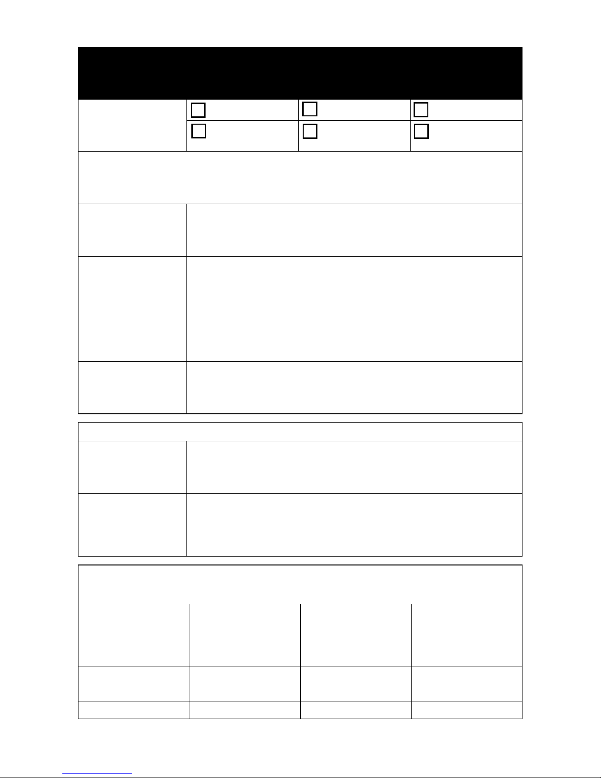
Osvědčení o jakosti a kompletnosti výrobku
Osvedčenie o akosti a kompletnosti výrobku / Testing certificate
Qualitätszertifikat des Produktes / Deklaracja Jakości i Kompletności
Název a typ výrobku
Názov a typ výrobku
Type
Bennenung und Typ
Nazwa i rodzaj produktu
MW2040 MIG
MW2040 MIG EUR
MW2050 MIG EUR
Výrobní číslo stroje: Výrobní číslo PCB:
Výrobné číslo: Výrobné číslo PCB:
Serial number: Serial number PCB:
Herstellungsnummer der Maschine: Herstellungsnummer PCB:
Numer produkcyjny maszyny: Numer produkcyjny PCB:
Výrobce
Výrobca
Producer
Produzent
Producent
Razítko OTK
Pečiatka OTK
Stamp an signature OTK
Stempel OTK
Pieczątka OTK
Datum výroby
Dátum výroby
Date of production
Datum der Produktion
Data produkcji
Kontroloval
Kontroloval
Inspected by
Geprüft von
Sprawdził
Záruční list / Záručný list / Warranty certificate / Garantieschein / Karta Gwarancyjna
Datum prodeje
Dátum predaja
Date of sale
Verkaufsdatum
Data sprzedaży
Razítko a podpis prodejce
Pečiatka a podpis predajca
Stamp and signature of seller
Stempel und Unterschrift
des Verkäufers
Pieczątka i podpis sprzedawcy
Záznam o provedeném servisním zákroku / Záznam o prevedenom servisnom zákroku
Repair note / Eintrag über durchgeführten Serviceeingriff
Zapis o wykonaniu interwencji serwisowej
Datum převzetí servisem
Dátum prevzatia servisom
Date of take-over
Datum Übernahme durch
Servisabteilung
Data odbioru przez serwis
Datum provedení opravy
Dátum prevzatia z opravy
Date of repair
Datum Durchführung der
Reparatur
Data wykonania naprawy
Číslo reklam. protokolu
Číslo reklam. protokolu
Number of repair form
Nummer des Reklamationsprotokoll
Numer protokołu reklamacyj
Podpis pracovníka
Podpis pracovníka
Signature of serviceman
Signature of serviceman
Unterschrift von Mitarbeiter
Podpis pracownika
Page 28

- 28 -
Poznámky / Poznámky / Note / Bemerkungen / Uwagi
Page 29
- 29 -
Výrobce si vyhrazuje právo na změnu.
Výrobca si vyhradzuje právo na zmenu.
The producer reserves the right to modification.
Hersteller behalten uns vor Recht für Änderung.
Producent zastrzega sobie prawo do zmian.
 Loading...