

Page 1
17/03/2014 v2.2
ENGLISH
0
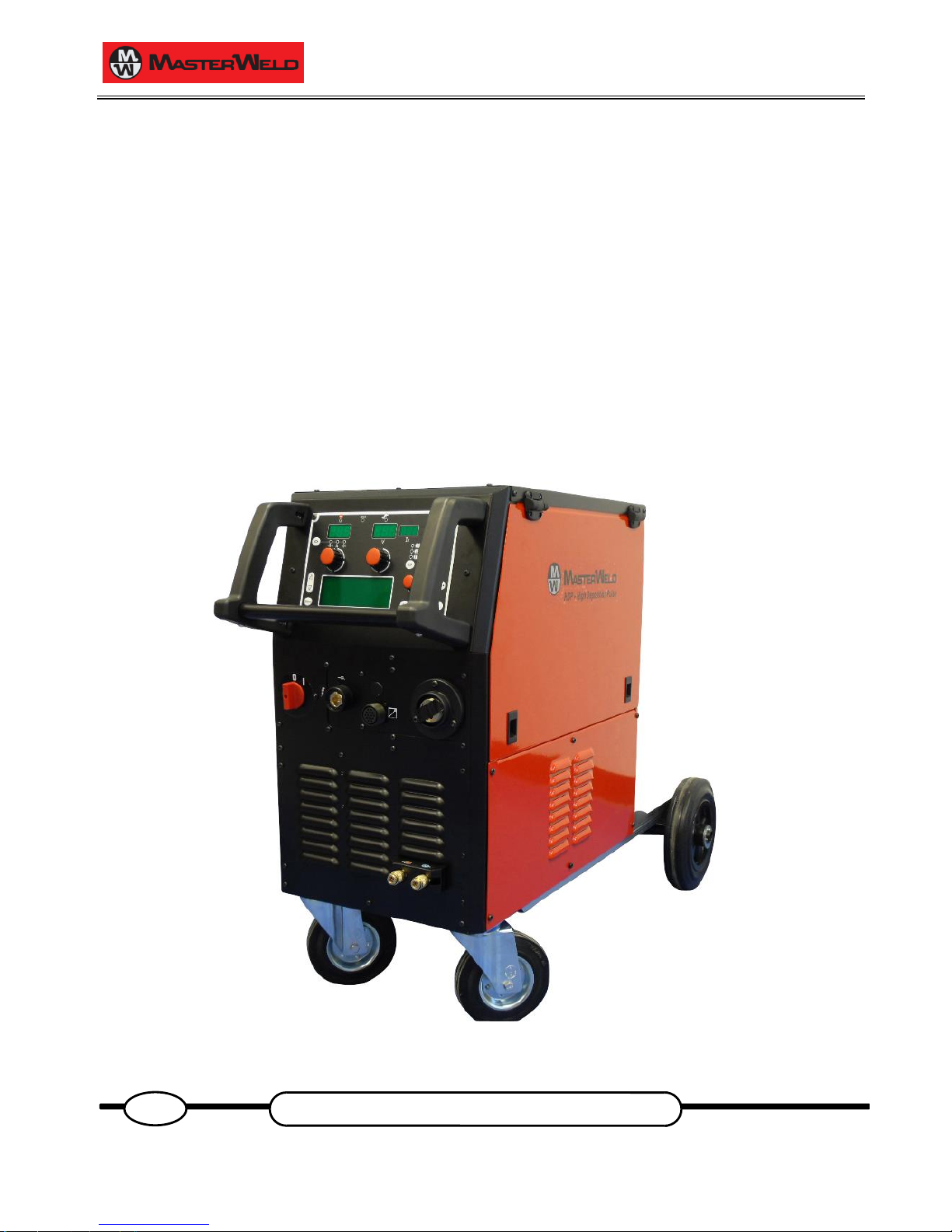
MasterWeld 321 HDP
Instruction manual
GB
Page 2

17/03/2014 v2.2
ENGLISH
0
Page 3

17/03/2014 v2.2
ENGLISH
0
1 INTRODUCTION ..................................................................... 4
2 FRONT PANEL ....................................................................... 4
3 REAR PANEL ......................................................................... 5
4 INSTALLATION ...................................................................... 5
4.1 UNIT ASSEMBLY .................................................................... 5
4.2 CONNECTIONS TO THE ELECTRICAL MAINS NETWORK . 6
4.3 WIRE SPOOL POSITIONING ................................................. 6
4.4 POSITIONING THE WIRE IN THE WIRE FEEDER ................ 6
4.5 CONNECTIONS TO SOCKETS .............................................. 7
5 USER INTERFACE ................................................................. 9
6 UNIT POWER-UP.................................................................. 11
7 RESET (LOAD FACTORY SETTINGS) ................................ 11
7.1 PARTIAL RESET ................................................................... 11
7.2 TOTAL RESET ...................................................................... 11
8 SET-UP (INITIAL SET-UP OF THE WELDING POWER
SOURCE) .............................................................................. 12
COOLER ACTIVATION .................................................................... 12
REMOTE CONTROLLER SELECTION ........................................... 12
ADJUSTMENTS BLOCK SELECTION ............................................. 12
PUSH PULL ...................................................................................... 12
SELECTION OF BURN TYPE .......................................................... 12
8.1 LOCKING PROCEDURE....................................................... 13
Enabling ............................................................................................ 13
Disabling ........................................................................................... 13
8.2 TORCH LOADING ................................................................. 14
9 ALARMS MANAGEMENT .................................................... 14
AL. HEA. ........................................................................................... 14
AL. COO. .......................................................................................... 14
Err. C0 ............................................................................................... 14
Err. C1 ............................................................................................... 14
Err. C2 ............................................................................................... 14
Err. C4 ............................................................................................... 14
Err. C11 ............................................................................................. 14
Err. C12 ............................................................................................. 14
10 PARAMETERS ACTIVATION............................................... 15
Working voltage ................................................................................ 15
Welding inductance ........................................................................... 15
Wire feed rate ................................................................................... 15
Welding current ................................................................................. 15
Thickness .......................................................................................... 15
Programs .......................................................................................... 15
Hot Start ............................................................................................ 15
Crater Filler ....................................................................................... 15
3 Levels Slope .................................................................................. 15
Soft Start ........................................................................................... 15
Motor Slope ....................................................................................... 15
Bourn Back ....................................................................................... 15
Post gas time .................................................................................... 15
Pre gas time ...................................................................................... 15
10.1 WELDING PARAMETERS .................................................... 16
11 WELDING SETTINGS ........................................................... 17
11.1 MIG/MAG WELDING ............................................................. 17
11.1.1 SETTING MIG/MAG PARAMETERS (MAIN WELDING
PARAMETERS) ................................................................................ 17
11.1.2 MIG/MAG PARAMETERS SETTING (2ND LEVEL)......................... 18
11.1.3 MIG/MAG PARAMETERS SETTING (GAS MENU) ......................... 18
12 JOBS MANAGEMENT .......................................................... 19
12.1 SAVING A JOB ...................................................................... 19
12.2 LOADING A USER JOB OF FACTORY SET JOB ................ 19
12.3 DELETING A JOB ................................................................. 19
13 TORCH TRIGGER MODES .................................................. 20
13.1 2T MIG/MAG WELDING ........................................................ 20
13.2 4T MIG/MAG WELDING ........................................................ 20
13.3 3 LEVEL MIG/MAG WELDING .............................................. 20
14 TECHNICAL DATA ............................................................... 21
15 SPARE PARTS ..................................................................... 22
15.1 321 HDP ................................................................................ 22
15.2 WIRE FEEDER MOTOR ....................................................... 24
15.3 WIRE FEEDER ROLLS ......................................................... 25
16 ELECTRICAL DIAGRAM ..................................................... 26
16.1 321 HDP ................................................................................ 26
16.2 REMOTE CONTROLLER ..................................................... 27
16.2.1 RC03: ELECTRICAL DIAGRAM ...................................................... 27
16.2.2 RC04: ELECTRICAL DIAGRAM ...................................................... 27
16.2.3 RC05: ELECTRICAL DIAGRAM ...................................................... 28
16.2.4 RC06: ELECTRICAL DIAGRAM ...................................................... 28
16.3 PUSH-PULL (OPTIONAL) ..................................................... 28
Page 4
17/03/2014 v2.2
ENGLISH
0
1 INTRODUCTION
IMPORTANT!
This handbook must be consigned to the user prior to
installation and commissioning of the unit.
Read the "General prescriptions for use" handbook supplied
separately from this handbook before installing and
commissioning the unit.
The meaning of the symbols in this manual and the associated
precautionary information are given in the "General
prescriptions for use”.
If the "General prescriptions for use" are not present, it is
mandatory to request a replacement copy from the
manufacturer or from your dealer.
Retain these documents for future consultation.
KEY
This symbol identifies an action that occurs automatically as
a result of a previous action.
This symbol identifies additional information or a reference to
a different section of the manual containing the associated
information.
§
This symbol identifies a reference to a chapter of the manual.
This symbol accompanies important information concerning
the execution of the relevant operations.
321 HDP is a synergic three-phase inverter suitable for workshops,
car body repairs, light to medium carpentry and welding on
positioners.
Accessories that can be connected to the unit:
− liquid cooler for torches.
The available procedures in the MIG/MAG modality are:
PROCEDURE
TWO STEP (2T)
FOUR STEP (4T)
THREE LEVEL (3T)
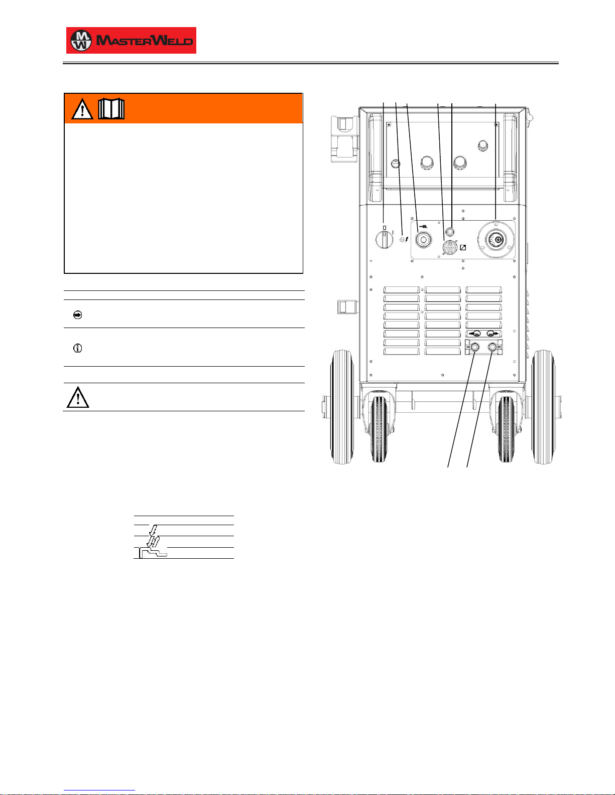
2 FRONT PANEL
1 2 3 4 5 6
7 8
1: Welding power source ON/OFF switch.
2: Mains protection ON LED.
This LED illuminates if an incorrect operating condition occurs:
− absence of a phase in the power supply line.
3: Earth welding socket.
4: Remote controller connector.
5: Provision for connection of the push pull torch (purchasing and
installing the relative kit).
6: MIG/MAG torch connector.
4: Connector for coolant hose.
Torch Power source
5: Connector for coolant hose.
Power source Torch
Page 5
17/03/2014 v2.2
ENGLISH
0
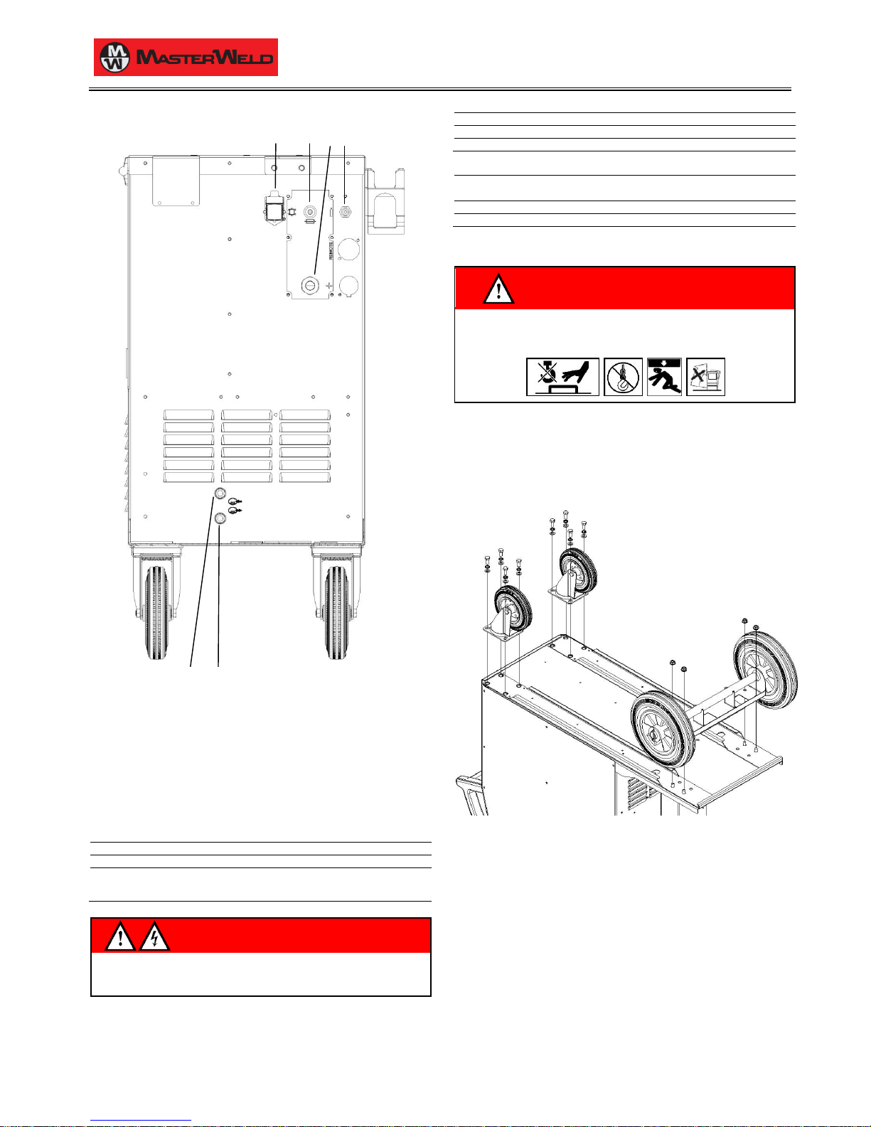
3 REAR PANEL
4 5 6 3
1 2
1: Connector for coolant hose.
Cooler Power source
2: Connector for coolant hose.
Power source Cooler
3: Gas rear connector. This is for the connection of the gas pipe
coming from the bundle of cables.
4: Cooler power feeding connector.
Voltage
230 V~
Current output
0.8 A
IP protection rating
IP20 (cap open)
IP66 (cap closed)
WARNING!
High voltage!
If the socket is not connected to any devices always close the cap:
presence of hazardous voltage levels!
5: Power supply transformer fuse.
Type
Delayed acting (T)
Amperage
2 A
Voltage
250 V
6: Power cable.
Total length
(including internal part)
4.5 m
Number and cross section of wires
4 x 2.5 mm
2
Power plug type
Not supplied
4 INSTALLATION
WARNING!
Lifting and positioning
Read the warnings highlighted by the following symbols in the
“General prescriptions for use”.
4.1 UNIT ASSEMBLY
1. Fit the front swivel wheels with the supplied screws.
2. Screw the fixed rear wheels to the studs in the base of the unit
and secure them with the supplied nuts.
3. Mount the cooler in the relevant location.
4. Screw the cooler fixing bracket to the welding power source
chassis using the supplied screws.
5. Screw the base of the cooler to the unit base using the supplied
screws.
6. Connect the plug of the cooler power cable to the cooler power
socket on the rear panel of the welding power source.
Page 6
17/03/2014 v2.2
ENGLISH
0
4.2 CONNECTIONS TO THE ELECTRICAL MAINS
NETWORK
The characteristics of the mains power supply to which the equipment
shall be connected are given in the section entitled “technical data” on
page 21.
The machine can be connected to motorgenerators provided their
voltage is stabilised.
Connect/disconnect the various devices with the machine switched
off.
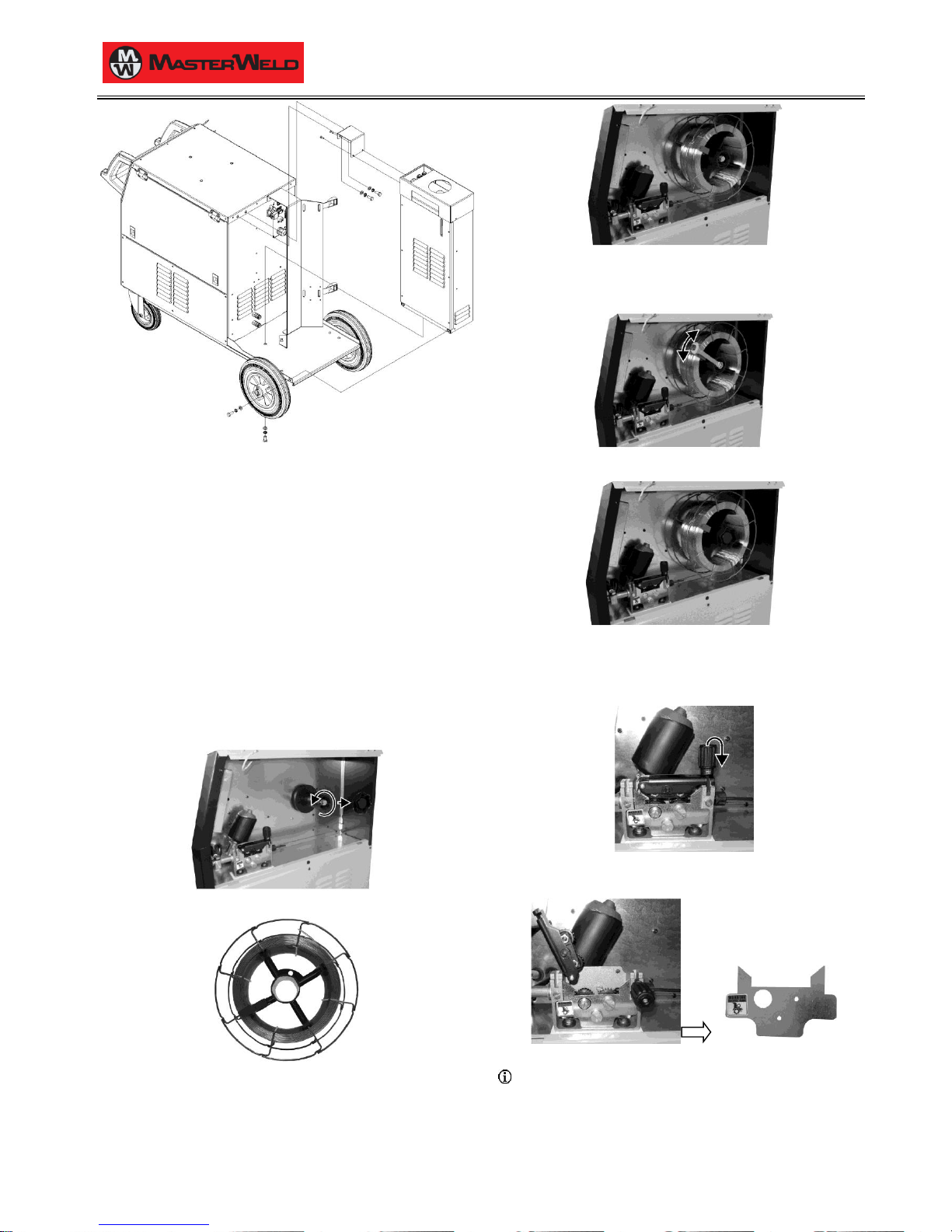
4.3 WIRE SPOOL POSITIONING
1. Open the unit side door to gain access to the spool compartment.
2. Unscrew the cap of the spool holder.
3. If necessary, fit an adapter for the wire spool.
4. Fit the spool in the spool holder, ensuring it is located correctly.
5. Adjust the spool holder braking system by tightening/loosening the
screw in such a way that the wire feed force is not excessive and
when the spool stops rotating no excess wire is released.
6. Refit the plug.
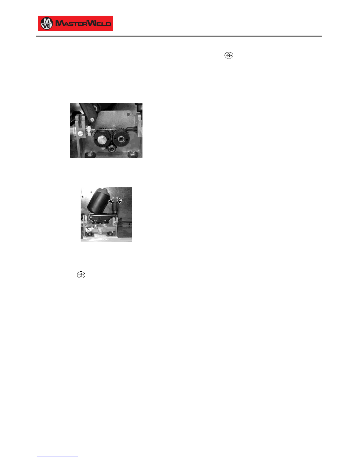
4.4 POSITIONING THE WIRE IN THE WIRE FEEDER
1. Lower the wire feeder pressure devices.
2. Raise the wire feeder pressure arms.
3. Remove the protective cover.
4. Check that the feed rolls are suitable for the wire gauge.
§ 15.3 WIRE FEEDER ROLLS
− The diameter of the roll groovemust be compatible with the
diameter of the welding wire.
− The roll must be of suitable shape in relation to the composition of
the wire material.
Page 7
17/03/2014 v2.2
ENGLISH
0
− The groove must feature a "U" profile for soft materials
(Aluminium and its alloys, CuSi3).
− The groove must be "V" shaped for harder materials (SG2-SG3,
stainless steels).
− Rolls with a knurled groove profile are available for flux-cored
wire.
5. Feed the wire between the wire feeder rolls and insert it into the
MIG/MAG TORCH connector plug.
6. Make sure the wire is located correctly in the roll grooves.
7. Close the wire feeder pressure arms.
8. Adjust the pressure system so that the arms press the wire with a
force that does not deform it while also ensuring constant feed
rate without slipping.
9. Refit the protective cover.
10. Set the welding power source ON/OFF switch to “I” (unit
powered).
11. Feed the wire through the torch until it protrudes from the tip,
pressing button on the unit front panel.
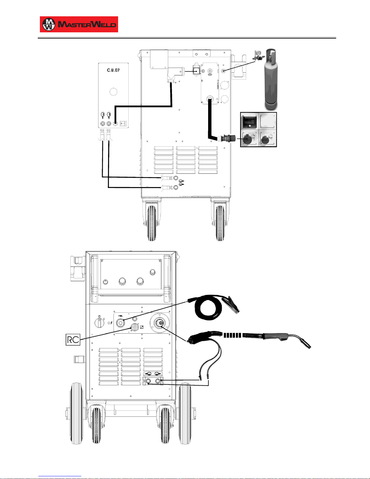
4.5 CONNECTIONS TO SOCKETS
1. Set the welding power source ON/OFF switch to “O” (unit de-
energized).
2. Plug the power cable plug into a mains socket outlet.
3. Connect the gas hose from the welding gas cylinder to the rear
gas socket.
4. Open the cylinder gas valve.
5. Connect the power supply cable of the cooling unit to the auxiliary
power socket on the power source.
6. Attach the coolant hoses to the relevant connectors on the cooler
and on the power source rear panel.
7. Connect the MIG/MAG torch plug to the EURO TORCH welding
socket.
8. Attach the coolant hoses of the MIG/MAG torch to the relevant
connectors on the power source front panel.
9. Connect the plug of the ground clamp to the welding socket on the
basis of the polarity required.
10. Connect the earth clamp to the workpiece being processed.
11. Set the welding power source ON/OFF switch to “I” (unit
powered).
12. Feed the wire through the torch until it protrudes from the tip,
pressing button on the unit front panel.
13. Select the torch trigger procedure on the user interface.
14. Press the torch trigger with the torch well clear of any metal parts.
This serves to open the gas solenoid valve without striking the
welding arc.
15. Use the flow control valve to adjust the flow of gas as required
while the gas is flowing out.
16. Set the required welding parameter values on the user interface.
17. On connecting and enabling a remote controller [RC] certain
settings can be modified from said controller without having to
take action on the user interface of the welding power source.
The system is ready to start welding.
MIG/MAG installation
Page 8
17/03/2014 v2.2
ENGLISH
0
Page 9
17/03/2014 v2.2
ENGLISH
0
9/30
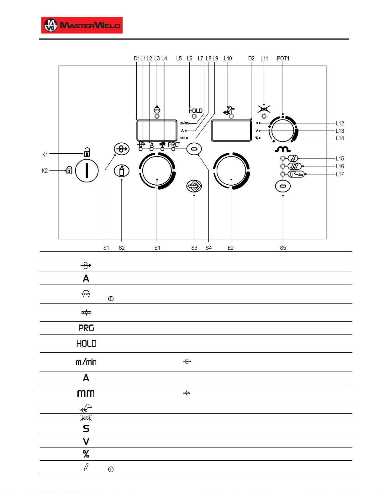
5 USER INTERFACE
CODE
SYMBOL
DESCRIPTION
L1
When this LED illuminates the following parameter can be set: WIRE FEED RATE
The value appears on the following display: D1
L2
When this LED illuminates the following parameter can be set: WELDING CURRENT
The value appears on the following display: D1
L3
This LED illuminates to show an anomaly in the operating conditions.
An alarm message appears on the following display: D1-D2
§ 9 ALARMS MANAGEMENT
L4
When this LED illuminates the following parameter can be set: WELDING THICKNESS
(Reference is made to "T" fillet welds on identical thicknesses. The relative value is purely guideline).
The value appears on the following display: D1
L5
When this LED illuminates the following parameter can be set: WELDING PROGRAM
The value appears on the following display: D1
L6
Illuminates to show the last voltage and current values measured during welding.
The LED switches off when a new welding procedure is started, or when any of the welding settings is modified.
The value appears on the following displays: D1-D2
L7
Illuminates to show a value in the following unit of measurement: METRES PER MINUTE
Illuminates together with the following LED:
The value appears on the following display: D1
L8
Illuminates to show a value in the following unit of measurement: AMPERES
The value appears on the following display: D1
L9
Illuminates to show a value in the following unit of measurement: MILLIMETRES
Illuminates together with the following LED:
The value appears on the following display: D1
L10
This LED illuminates to confirm the presence of power on the output sockets.
L11
Illuminates to show that the cooling unit pressure switch does not detect any pressure.
L12
Illuminates to show a value in the following unit of measurement: SECONDS
The value appears on the following display: D2
L13
Illuminates to show a value in the following unit of measurement: VOLTS
The value appears on the following display: D2
L14
Illuminates to show a value in the following unit of measurement: PERCENTAGE
The value appears on the following display: D2
L15
Illumination shows that the following function has been activated: 2 times procedure
§ 13.1 2T MIG/MAG WELDING
Page 10
17/03/2014 v2.2
ENGLISH
0
10/30
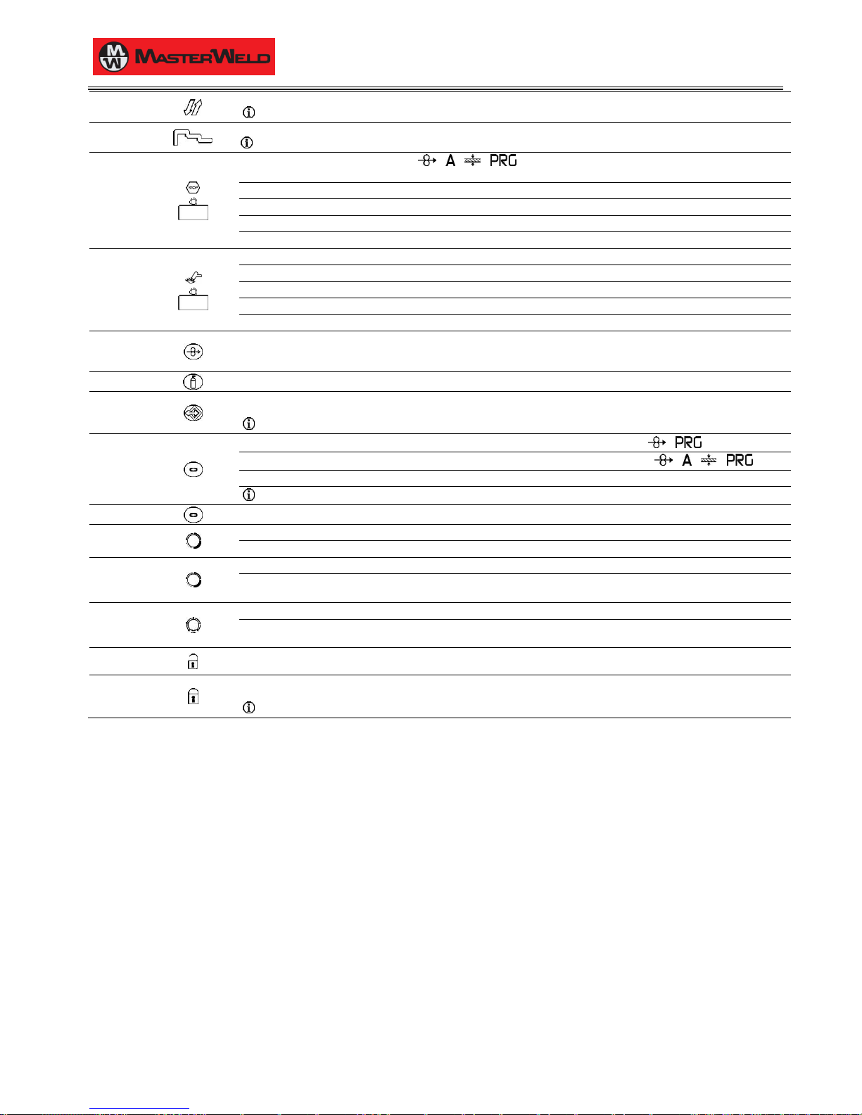
L16
Illumination shows that the following function has been activated: 4 times procedure
§ 13.2 4T MIG/MAG WELDING
L17
Illumination shows that the following function has been activated: 3 levels procedure
§ 13.3 3 LEVEL MIG/MAG WELDING
D1
During illumination of the following LEDs: / / /
The display shows the value of the selected parameter.
Welding: The display shows the effective amperes value during welding.
HOLD function (at welding end): The display shows the latest measured current value.
Menu function: The display shows the acronym of the parameter or function to be adjusted.
Programs setting: The display shows the message P “program no.”.
D2
Data setting: The display shows the value, in Volts, of the selected welding voltage.
Welding: The display shows the effective voltage value during welding.
HOLD function (at welding end): The display shows the latest measured voltage value.
Menu function: The display shows the value of the parameter or function to be adjusted.
Programs setting: The display shows the acronym of the material to be welded on the basis of the selected synergic curve.
S1
This button activates wire feed to insert it through the MIG/MAG torch.
The insertion speed is 2 m/min for 3 seconds, subsequently increasing to 10 m/min.
This function produces a slower feed rate and hence greater precision when inserting the wire when it enters the torch nozzle.
S2
This button opens the gas solenoid valve to fill the circuit and calibrate the pressure with the regulator on the gas cylinder.
S3
Press the button once to open the JOB upload menu.
Hold down the button for 3 seconds to gain access to the JOB save/delete menu.
§ 11 WELDING SETTINGS
S4
Manual MIG/MAG mode: The button cycles through the following LEDs in sequence, selecting only one: /
Synergic MIG/MAG mode: The button cycles through the following LEDs in sequence, selecting only one: / / /
Data setting: Hold down the button for 3 seconds to gain access to the second level menu.
§ 11.1.2 MIG/MAG PARAMETERS SETTING (2ND LEVEL)
S5
This button selects the torch trigger procedure.
E1
Data setting: The encoder adjusts the main welding (and synergy) parameter, shown on the following display: D1
Menu function: The encoder selects the function or parameter to be adjusted.
E2
Manual MIG/MAG mode: The encoder adjusts the welding voltage, and the relative value is shown, in volts, on the following display: D2
Synergic MIG/MAG mode: The encoder is used to correct the factory-set value of the selected synergic curve, the value of which is shown on
the following display: D2
POT1
Manual MIG/MAG mode: The potentiometer sets the inductance value.
Synergic MIG/MAG mode: The potentiometer sets the inductance value from the minimum to the maximum permissible value in accordance
with the selected synergic curve.
K1
Control release: When the key is in this position all the functions of the machine can be changed.
K2
Control lock: When the key is in this position, some functions of the panel are disabled.
The functions disabled depend on the blocking status selected.
§ 8.1 LOCKING PROCEDURE
Page 11
17/03/2014 v2.2
ENGLISH
0
11/30
6 UNIT POWER-UP
Set the welding power source ON/OFF switch to “I” to switch on the unit.
AL. HEA.
The message appears on the following displays: D1-D2
First power-up or power-ups following a RESET procedure
The welding power source sets up for welding with the factory presets.
Subsequent power-ups
The welding power source sets up for welding in the latest stable welding configuration that was active at the time of power-off.
7 RESET (LOAD FACTORY SETTINGS)
7.1 PARTIAL RESET
The reset procedure involves restoration of the parameter values and settings, except the following settings:
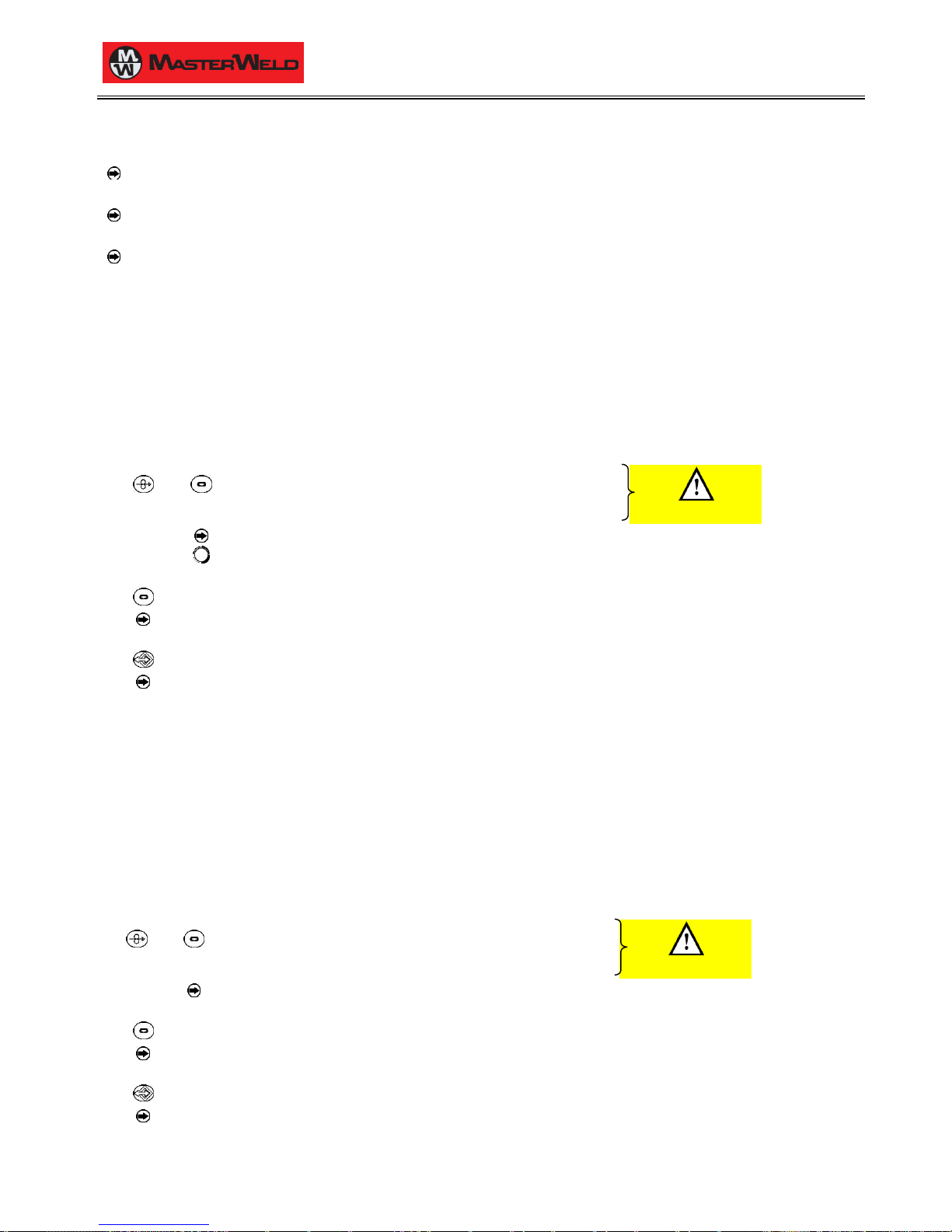
− settings of the SETUP menu.
− saved JOBS.
Set the welding power source ON/OFF switch to “O” to switch the unit off.
S1 S5 Hold down both buttons simultaneously.
Set the welding power source ON/OFF switch to “I” to switch on the unit.
SIMULTANEOUS ACTIONS
rEC FAC
The message appears on the following displays: D1-D2
E2 Select the following setting with the encoder: rEC PAr
Exit without confirmation
Press any button (except S3).
This action will automatically close the menu.
Exit with confirmation
S3 Press the button.
This action will automatically close the menu.
Wait for the memory clear procedure to terminate.
7.2 TOTAL RESET
The reset procedure involves complete restoration of the default values, parameters and memory settings set in the factory.
All memory locations will be reset and hence all your personal welding settings will be lost!
The reset procedure is useful in the following cases:
− too many changes made to the welding parameters so user finds it difficult to restore defaults.
− unidentified software problems that prevent the welding power source from functioning correctly.
Set the welding power source ON/OFF switch to “O” to switch the unit off.
S1 S5 Hold down both buttons simultaneously.
Set the welding power source ON/OFF switch to “I” to switch on the unit.
SIMULTANEOUS ACTIONS
rEC FAC
The message appears on the following displays: D1-D2
Exit without confirmation
Press any button (except S3).
This action will automatically close the menu.
Exit with confirmation
S3 Press the button.
This action will automatically close the menu.
Wait for the memory clear procedure to terminate.
Page 12
17/03/2014 v2.2
ENGLISH
0
12/30
8 SET-UP (INITIAL SET-UP OF THE WELDING POWER SOURCE)
With locked status active it is not possible to access this function.
§ 8.1 LOCKING PROCEDURE
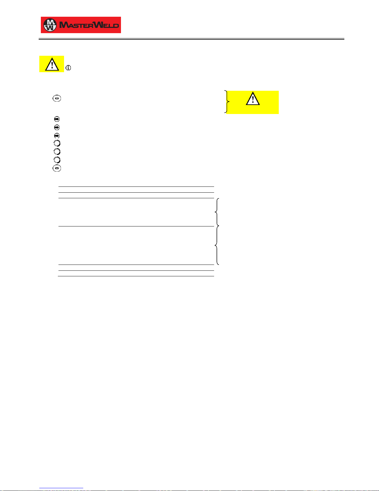
Set the welding power source ON/OFF switch to “O” to switch the unit off.
S4 Hold down the button.
Set the welding power source ON/OFF switch to “I” to switch on the unit.
SIMULTANEOUS ACTIONS
Set UP
The message appears for a few seconds on the following displays: D1-D2
The acronym relative to the setting to be edited appears on the following displays: D1
The value relative to the selected setting appears on the following displays: D2
E1 Using the encoder, select the setting to be changed.
E2 Using the encoder, edit the value of the selected setting.
E1 Select the following setting with the encoder: ESC
S4 Press any button to save the setting and quit the menu.
Tab. 1 - Setup settings
ACRONYM
SETTING
MIN
DEFAULT
MAX
Coo
COOLER ACTIVATION
Aut
Aut
on
rC
REMOTE CONTROLLER SELECTION
oFF
oFF
06
oFF
No control
03
n°1 potentiometer
04
n°2 potentiometers
05
n°1 UP/DOWN
06
n°2 UP/DOWN
LoC
ADJUSTMENTS BLOCK SELECTION
oFF
oFF
3
oFF
All adjustments enabled.
1
All adjustments are disabled with the exceptions
shown in Tab. 2 page 13.
2
All adjustments are disabled with the exceptions
shown in Tab. 2 page 13.
3
All adjustments are disabled with the exceptions
shown in Tab. 2 page 13.
PP
PUSH PULL
on
oFF
oFF bb
SELECTION OF BURN TYPE
SPc (*1)
Std
Std (*2)
*1: Anti-sticking function present to prevent the wire from sticking.
*2: No wire sticking control, just final wire cut.
Cooler activation
− ON= The cooler is always running when the power source is switched on. This mode is preferable for heavy duty and automatic welding
procedures.
− OFF= The cooler is always disabled because an air-cooled torch is in use.
− AUT= When the unit is switched on the cooler is switched on for 15 s. During welding procedures the cooler runs constantly. When welding is
terminated the cooler continues to run for 90 s + a number of seconds equivalent to the average current value shown using the HOLD
function.
Page 13

17/03/2014 v2.2
ENGLISH
0
13/30
8.1 LOCKING PROCEDURE
The procedure inhibits unit adjustments, allowing the user to modify only certain settings depending on the selected lock status.
The procedure is used to prevent accidental alteration of the unit settings and welding settings by the operator.
Enabling
If no locking status is selected (LOC = OFF) and if you wish to set up a limitation on use of the power source, display the LOC function in the
SETUP menu.
Open the Setup menu.
The acronym relative to the setting to be edited appears on the following displays: D1
The value relative to the selected setting appears on the following displays: D2
E1 Select the following setting with the encoder: LoC
E2 Use the encoder to select the required lock status.
E1 Select the following setting with the encoder: ESC
S4 Press any button to save the setting and quit the menu.
Tab. 2 - Functions not disabled by Locks
LOC
USER INTERFACE
RC03
RC04
RC05
RC06
oFF
All adjustments enabled.
Key K1 disabled.
All adjustments enabled.
All adjustments enabled.
All adjustments enabled.
All adjustments enabled.
1
Selection of torch trigger procedure (button S5)
Display of main welding parameters (button S4)
Arc correction (encoder E2)
Wire insertion (button S1)
Gas test (button S2)
Arc correction
(Potentiometer Pot2)
Arc correction (UP/DOWN
lever 2)
2
Selection of torch trigger procedure (button S5)
Display of main welding parameters (button S4)
Arc correction (encoder E2)
Synergy (encoder E1)
Wire insertion (button S1)
Gas test (button S2)
All adjustments enabled.
All adjustments enabled.
All adjustments enabled.
All adjustments enabled.
3
(*1)
Selection of torch trigger procedure (button S5)
Display of main welding parameters (button S4)
JOB selection (encoder E2)
Wire insertion (button S1)
Gas test (button S2)
Scroll JOBS (UP/DOWN
lever 1)
Scroll JOBS (UP/DOWN
lever 1)
*1: The LOC 3 setting becomes active only when a JOB is loaded. When no JOB is loaded, the user interface is completely unlocked.
Disabling
If a lock status is selected, you can only edit parameters permitted by the currently active lock status.
Open the Setup menu.
The acronym relative to the setting to be edited appears on the following displays: D1
The value relative to the selected setting appears on the following displays: D2
E1 Select the following setting with the encoder: LoC
E2 Select the following setting with the encoder: oFF
E1 Select the following setting with the encoder: ESC
S4 Press any button to save the setting and quit the menu.
Page 14
17/03/2014 v2.2
ENGLISH
0
14/30
8.2 TORCH LOADING
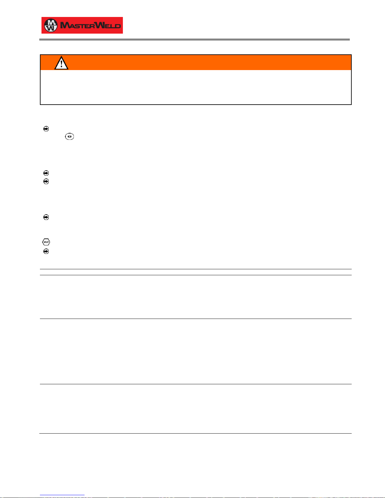
WARNING!
Make sure the torch in use is correctly sized in relation to the welding current required and for the available and selected cooling type. This
prevents the risk of burns to which the operator is potentially exposed, potential faults, and irreversible damage to the torch and the system.
If a torch is installed or replaced while the unit is running, the circuit of the newly installed must be filled with coolant to avoid the risk of damage
to the torch in the case of high voltage arc strikes without any liquid in the circuit.
Power-up with operation of the cooler set to "ON" or "AUTO" mode
AL. COO.
The message appears on the following displays: D1-D2
(any)
Press the button or torch trigger to repeat the checking procedure for an additional 15 seconds.
If the problem persists rectify the cause of the alarm.
Power-up with operation of the cooler set to "OFF"
Operation of the cooler and the cooler alarm are disabled.
Welding is performed without liquid cooling of the torch.
Torch change-over with operation of the cooler set to "AUTO"
Press and release the torch trigger.
This serves to start the cooler for 15 seconds to fill the torch cooling circuit.
9 ALARMS MANAGEMENT
This LED illuminates if an incorrect operating condition occurs.
An alarm message appears on the following display: D2
Tab. 3 - Alarm messages
MESSAGE
MEANING
EVENT
CHECKS
AL. HEA.
Overheating alarm
Indicates tripping of the welding power
source thermal protection.
Leave the unit running so that the
overheated components cool as rapidly
as possible.
When the unit has cooled, the welding
power source will reset automatically.
All functions disabled.
Exceptions:
- cooling fan.
- cooler (if switched on).
- Make sure that the power required by the
welding process is lower than the maximum
rated power output.
- Check that the operating conditions are in
compliance with the welding power source data
plate specifications.
- Check for the presence of adequate air
circulation around the welding power source.
AL. COO.
Cooler alarm
Indicates insufficient pressure in the torch
liquid cooling circuit.
All functions disabled.
Exceptions:
- cooling fan.
The alarm message persists on the display until the first operation is
performed on the user interface.
Cooler ON: the alarm is signalled as long as the unit alarm is active
and the cooler presence signal persists.
Cooler OFF: the alarm is never signalled, irrespective of the
circumstances.
Cooler AUTO: the alarm is signalled at the times in which the unit is
running; the alarm signal occurs as long as the unit presence signal
persists.
- Check that the connection to the cooler is
correct.
- Check that the O/I switch is set to I and that it
illuminates when the pump is running.
- Check that the cooler is filled with coolant.
- Check that the cooling circuit is liquid tight,
notably the torch hoses and the internal
connections of the cooler.
Err. C0
Err. C1
Err. C2
Err. C4
Err. C11
Err. C12
CAN BUS Communication Alarm
Indicates the presence of problems in
data communication between the power
source and wire feeder.
When the unit has cooled, the welding
power source will reset automatically.
Exit the alarm state by performing one of
the following actions:
- Switch the power source off.
All functions disabled.
Exceptions:
- cooling fan.
- cooler (if switched on).
- Check that the connecting cable between
power source and wire feeder is intact and
make sure the connectors are securely
tightened.
Page 15
17/03/2014 v2.2
ENGLISH
0
15/30
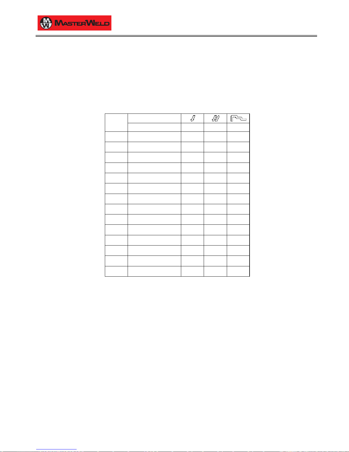
10 PARAMETERS ACTIVATION
The welding parameters are available in accordance with the selected welding mode and procedure.
Certain parameters are available only after other parameters or functions of the unit have been enabled or set.
The table shows the settings required to enable each parameter.
LEGEND:
✓: always available
1: not enabled with manual program P0.
MENU
PROCEDURE
PARAMETER
-
Working voltage
✓
✓
1
-
Welding inductance
✓
✓
1
1°
Wire feed rate
✓
✓
1
1°
Welding current
1
1
1
1°
Thickness
1
1
1
1°
Programs
✓
✓
1
2°
Hot Start
1
2°
Crater Filler
1 2°
3 Levels Slope
1
2°
Soft Start
✓
✓
1
2°
Motor Slope
✓
✓
1
2°
Bourn Back
✓
✓
1
2°
Post gas time
✓
✓
1
2°
Pre gas time
✓
✓
1
Page 16

17/03/2014 v2.2
ENGLISH
0
16/30
10.1 WELDING PARAMETERS
Welding inductance
Consequences of a higher value:
− "Softer welding".
− Less spatter.
− Less positive starting.
Consequences of a lower value:
− "Harder welding".
− More spatter.
− More reliable starting.
Hot Start
This function is useful when using aluminium alloy welding wire.
Consequences of a higher value:
− Greater heat output.
− Greater penetration.
Consequences of a lower value:
− "Cold" weld bead.
Crater Filler
This parameter serves to obtain a uniform deposit at the end of the
welding process to fill the crater with a reduced wire feed rate to
facilitate the deposition of filler material.
By keeping the torch trigger pressed during the 3rd time, the wire feed
rate is reduced (crater filler speed) thereby ensuring optimal crater
filling, until the POST GAS time is started by releasing the torch
trigger (4Th time).
Consequences of a higher value:
− Difficult crater filling (values greater than 100%).
Consequences of a lower value:
− Cold welding (values close to 1%).
3 Levels Slope
Establishes the duration of the slope between the 1st and 2nd time
and between the 3rd and 4Th time.
Soft Start
Determines the wire feed rate before the arc strike.
Calculated as a percentage of the programmed wire feed rate.
In Synergic welding the optimal soft start value (indicated with SYN)
varies in general with variations of the synergic parameters.
In Synergic welding, if the value soft start = SYN is selected the
welding power source will always have the optimal soft start value set
when the main welding parameter changes.
If you set a value other than SYN, this value is stored and fixed.
Consequences of a lower value:
− The start of welding is "softer".
Consequences of a higher value:
− The welding start may prove difficult.
Motor Slope
Time required to switch from SOFT START speed to welding speed.
Bourn Back
The burn back value is associated with the quantity of wire that is
burnt at the end of the welding procedure.
In Synergic welding the optimal burn back value (indicated with SYN)
varies in general with variations of the synergic parameters.
In Synergic welding, if the value burn back = SYN is selected the
welding power source will always have the optimal burn back value
set when the main welding parameter changes.
If you set a value other than SYN, this value is stored and fixed.
Consequences of a higher value:
− Wire significantly retracted into the torch nozzle.
Consequences of a lower value:
− Stick-out at welding start is longer.
Post gas time
Time of post gas delivery when the welding arc is extinguished.
This is useful when welding at high current values or with materials
that oxidise readily to cool the weld pool in an uncontaminated
atmosphere.
In the absence of specific requirements the value should generally be
kept low.
Consequences of a higher value:
− More effective pickling (improved appearance of workpiece at the
end of the welding pass).
− Higher gas consumption.
Consequences of a lower value:
− Lower gas consumption.
− Oxidation of electrode tip (more difficult arc strike).
Pre gas time
Time of gas delivery before the arc strike.
Consequences of a higher value:
− This parameter allows a shielded environment to be created,
thereby eliminating contaminants at the start of the welding pass.
Page 17
17/03/2014 v2.2
ENGLISH
0
17/30
11 WELDING SETTINGS
11.1 MIG/MAG WELDING
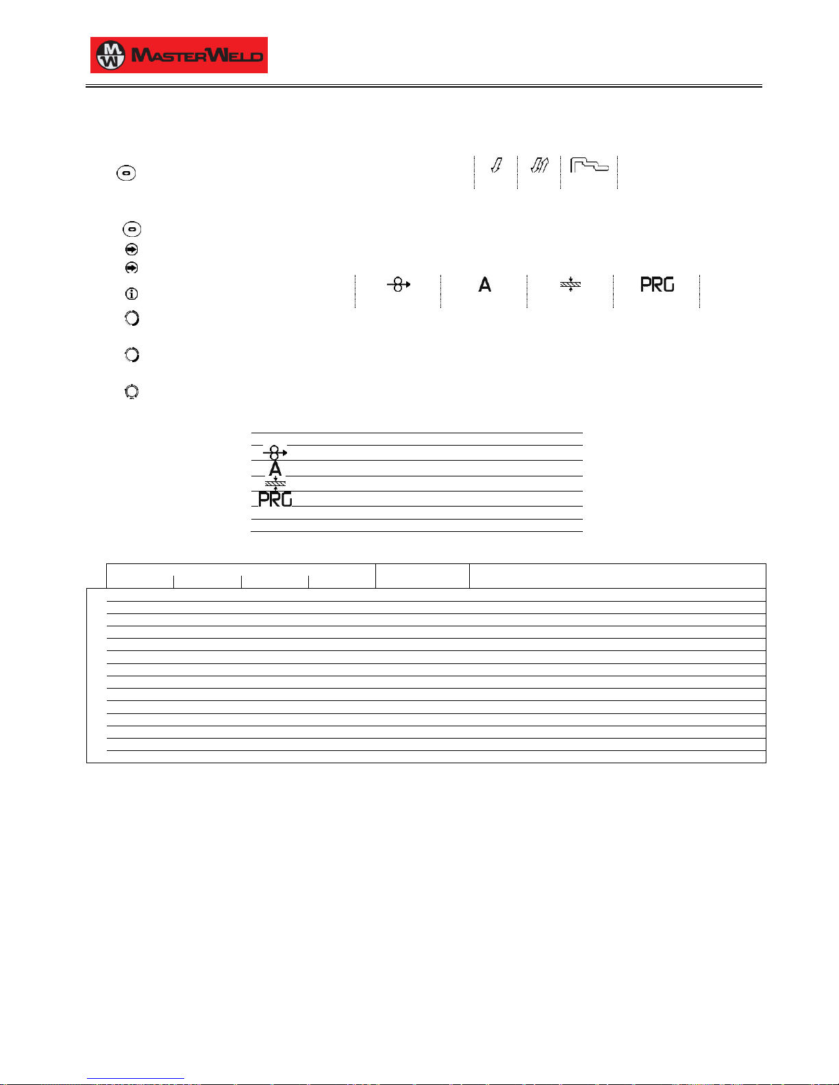
S5 Use this button to select one of the following torch trigger procedures:
2 STEP
4 STEP
3 LEVEL
11.1.1 SETTING MIG/MAG PARAMETERS (MAIN WELDING PARAMETERS)
S4 Press this button to scroll the list of settings to edit.
The LED associated with the selected setting will illuminate.
The value relative to the selected setting appears on the following displays: D1
The following settings are available:
WIRE FEED RATE
AMPERES
THICKNESS
PROGRAMS
E1 Using the encoder, edit the value of the selected setting.
The value is saved automatically.
E2 Using the encoder, edit the value of the following setting: WORKING VOLTAGE
The value is saved automatically.
POT1
Using the potentiometer, edit the value of the following setting: WELDING INDUCTANCE
Tab. 4 - Main welding parameters in MIG/MAG mode
PARAMETER
MIN
DEFAULT
MAX
WIRE FEED RATE
1.5 m/min
5.0 m/min
22.0 m/min
MIG/MAG WELDING CURRENT
-
Syn
-
*1
THICKNESS
-
Syn
-
*1
PROGRAMS
P0
P0
P34
WORKING VOLTAGE
10.0 V
20.0 V
40.0 V
WELDING INDUCTANCE
0 - 255
Tab. 5 - Programmed synergic curves
WIRE DIAMETER
ACRONYM
WIRE MATERIAL (GAS MIXTURE)
0.8
1.0
1.2
1.4
PROGRAMS
P0
P0
P0
P0
MAn
MANUAL
P1
P2
P3
--
FE
SG2/SG3 (80%Ar-20%CO2)
P4
P5
P6
--
FE
SG2/SG3 (92%Ar- 8%CO2)
P7
P8
P9
--
FE
SG2/SG3 (100%CO2)
P10
P11
P12
--
S.S.
INOX 308 (98%Ar-2%CO2)
P13
P14
P15
--
S.S.
INOX 316 (98%Ar-2%CO2)
P16
P17
P18
--
AL
AlMg5 (100%Ar)
P19
P20
P21
--
AL
AlSi5 (100%Ar)
P22
P23
P24
--
CU.S.
CuSi3 (100%Ar)
P25
P26
P27 CU.A.
CuAl8 (100%Ar)
--
--
P28
P29
rFC
RFCW (80%Ar-20%CO2)
--
--
P30
P31
bFC
BFCW (80%Ar-20%CO2)
--
--
P32
P33
MFC
MFCW (80%Ar-20%CO2)
P34
--
--
--
nPr
FREE PROGRAMS
*1: SYN= By synergy we mean a simple and fast way to regulate the generator. Through this function, an optimum balancing of all the welding
parameters in every position can be granted, thus helping the user.
This is the reason why the synergic curves of most of the wire types have been introduced, however these curves can be easily modified so
as to allow the user to optimise his own welding procedure.
NOTE: The synergic curves were created with reference to a fillet weld in position PB (horizontal-vertical) with 10 mm stick-out (distance from
torch to workpiece).
Page 18

17/03/2014 v2.2
ENGLISH
0
18/30
11.1.2 MIG/MAG PARAMETERS SETTING (2ND LEVEL)
S4 Hold down the button for 3 seconds to gain access to the 2nd level menu.
The acronym relative to the setting to be edited appears on the following displays: D1
The value relative to the selected setting appears on the following displays: D2
E1 Use the encoder to scroll the list of settings to edit.
E2 Using the encoder, edit the value of the selected setting.
Press any button to save the setting and quit the menu.
Tab. 6 - 2nd level menu parameters in MIG/MAG mode
ACRONYM
PARAMETER
MIN
DEFAULT
MAX
H.-S.
HOT START
1 %
130 %
200 %
C.-F.
CRATER FILLER
1 %
130 %
200 % S.3L.
3 LEVELS SLOPE
0.1 s
0.5 s
10.0 s
S.-S.
SOFT START
10 %
30 %
100 %
*1
SLO.
MOTOR SLOPE
0 ms
40 ms
200 ms
*1
b.-b.
BOURN BACK
0 ms
16 ms
200 ms
*1
11.1.3 MIG/MAG PARAMETERS SETTING (GAS MENU)
S2 Hold down the button for 3 seconds to gain access to the 2nd level menu.
The acronym relative to the setting to be edited appears on the following displays: D1
The value relative to the selected setting appears on the following displays: D2
E1 Use the encoder to scroll the list of settings to edit.
E2 Using the encoder, edit the value of the selected setting.
Press any button to save the setting and quit the menu.
Tab. 7 - Gas menu parameters in MIG/MAG mode
ACRONYM
PARAMETER
MIN
DEFAULT
MAX
Po.G.
POST GAS TIME
0.0 s
0.3 s
10.0 s
*1
Pr.G.
PRE GAS TIME
0.0 s
0 s
10.0 s
*1
*1: When a synergic program is loaded the default value of the parameter is defined automatically by the software and the message "SYN" will
be shown on the display.
Page 19

17/03/2014 v2.2
ENGLISH
0
19/30
12 JOBS MANAGEMENT
Personalised welding settings, or JOBs, can be saved in memory locations and subsequently uploaded.
Up to 99 jobs can be saved (j01-j99).
The settings of the SETUP menu are not saved.
12.1 SAVING A JOB
This function is available when welding mode is not active.
S3 Hold down the button for 3 seconds.
SA. J.xx
The message appears on the following displays: D1-D2
xx=
number of the first free job.
E2 Select the position in which to save the job with the encoder.
On selecting a currently occupied memory location, the job number flashes.
If you confirm at this point, the new job will overwrite the previously saved settings.
Exit without confirmation
Press any button (except S3).
This action will automatically close the menu.
Exit with confirmation
S3 Press the button.
This action will automatically close the menu.
12.2 LOADING A USER JOB OF FACTORY SET JOB
This function is available when welding mode is not active.
S3 Press and release the button.
LO. J.xx
Only when the jobs have been uploaded, the message is shown on the following displays: D1-D2
xx=
number of the latest job used.
nO Job
If there are no jobs in the memory the message is shown on the following displays: D1-D2
E2 Use the encoder to select the number of the job to be uploaded.
Exit without confirmation
Press any button (except S3).
This action will automatically close the menu.
Exit with confirmation
S3 Press the button.
J.xx
The number of the loaded job remains shown on display D2.
xx=
number of loaded job.
This action will automatically close the menu.
12.3 DELETING A JOB
This function is available when welding mode is not active.
S3 Hold down the button for 3 seconds.
SA. J.xx
The message appears on the following displays: D1-D2
E1 Select the following setting with the encoder:
Er. J.xx
The message appears on the following displays: D1-D2
xx=
number of the latest job used.
E2 Use the encoder to select the number of the job to be deleted.
Exit without confirmation
Press any button (except S3).
This action will automatically close the menu.
Page 20

17/03/2014 v2.2
ENGLISH
0
20/30
Exit with confirmation
S3 Press the button.
This action will automatically close the menu.
13 TORCH TRIGGER MODES
13.1 2T MIG/MAG WELDING
1. Bring the torch up to the workpiece.
2. Press (1T) and keep the torch trigger pressed.
The wire advances at the approach speed until making contact with the work.
3. The arc strikes and the wire feeder accelerates to the set feed rate value.
4. Release (2T) the trigger to start the weld completion procedure.
Gas flow continues for the time set in the post gas parameter (adjustable time).
13.2 4T MIG/MAG WELDING
1. Bring the torch up to the workpiece.
2. Press (1T) and release (2T) the torch trigger.
The wire advances at the approach speed until making contact with the work.
3. The arc strikes and the wire feeder accelerates to the set feed rate value.
4. Press (3T) the trigger to start the weld completion procedure.
Gas flow continues until the torch trigger is released.
5. Release (4T) the torch trigger to start the post gas procedure (adjustable time).
13.3 3 LEVEL MIG/MAG WELDING
1. Bring the torch up to the workpiece.
2. Press (Level 1) the torch trigger.
The wire advances at the approach speed until making contact with the work.
3. The welding arc strikes and the wire feed rate changes to the first welding level, which is set as a percentage of the normal welding feed rate.
This first level is used to create the weld pool: for example, when welding aluminium a value of 130% is recommended.
4. Release (Level 2) the torch trigger to switch to the normal welding feed rate.
5. Press the torch trigger again (Level 3) to switch to the third welding level, which is set as a percentage of the normal welding feed rate.
This third level is used to complete the weld and fill the final crater (CRATER FILLER) in the weld pool: for example, when welding aluminium
a value of 80% is recommended.
6. Release the torch trigger a second time to close the weld and run the post gas procedure.
Page 21

17/03/2014 v2.2
ENGLISH
0
21/30
14 TECHNICAL DATA
Model
321 HDP
Construction standards
EN 60974-1
EN 60974-5
EN 60974-10 Class A
Supply voltage
3 x 400 V~±15 % / 50-60 Hz
Z
max
*
165 mΩ
Mains protection
25 A Delayed
Dimensions ( L x D x H )
1110 x 530 x 750 mm
Weight
61 kg
Insulation class
H
Protection rating
IP23
Cooling
AF
Maximum gas pressure
0.5 MPa (5 bar)
MIG/MAG welding voltage
15.5 - 30.0 V
Motor speed
1.0 - 20.0 m/min
Wire spool: (dimensions/weight)
300 mm / 15 kg
Temperature of the environment
40°C
Welding mode
MIG/MAG
Static characteristic
Work cycle
45 %
60 %
100 %
Welding current
320 A
280 A
230 A
Working voltage
30.0 V
28.0 V
25.5 V
Maximum input power
11.6 KVA
9.5 KVA
7.1 KVA
11.1 KW
9.0 KW
6.7 KW
Maximum supply current
17.0 A
13.1 A
10.3 A
Maximum Effective Supply Current
11.4 A
10.5 A
10.3 A
Open-circuit voltage (U0)
53 V
Reduced no-load voltage (Ur)
10 V
*This equipment complies with IEC 61000-3-12 provided that the maximum permissible system impedance Z
MAX
is less than or equal to 165 mΩ at the interface point between the
user's supply and the public system. It is the responsibility of the installer or user of the equipment to ensure, by consultation with the distribution network operator if necessary, that
the equipment is connected only to a supply with maximum permissible system impedance Z
MAX
less than or equal to 165 mΩ.
Page 22
17/03/2014 v2.2
ENGLISH
0
22/30
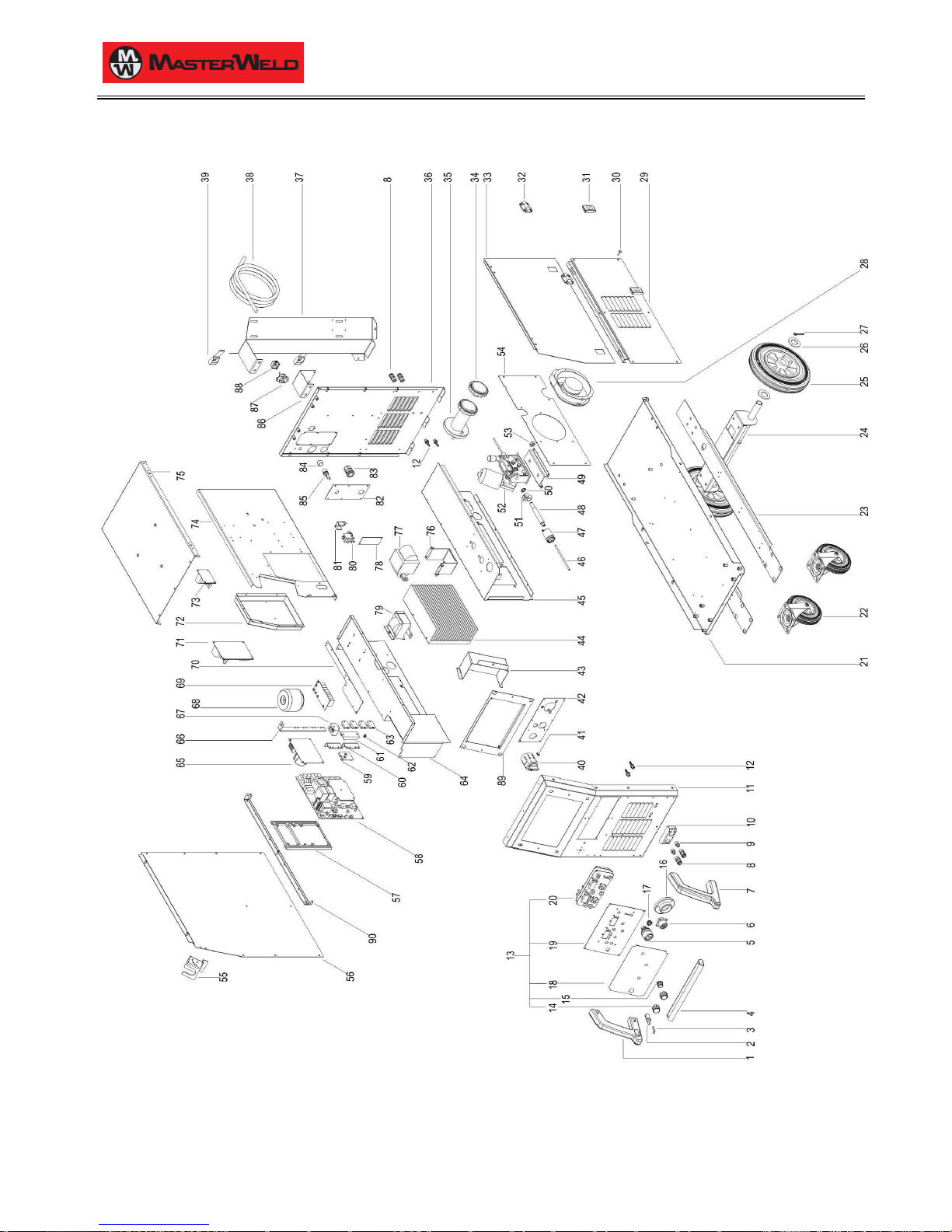
15 SPARE PARTS
15.1 321 HDP
Page 23
17/03/2014 v2.2
ENGLISH
0
23/30
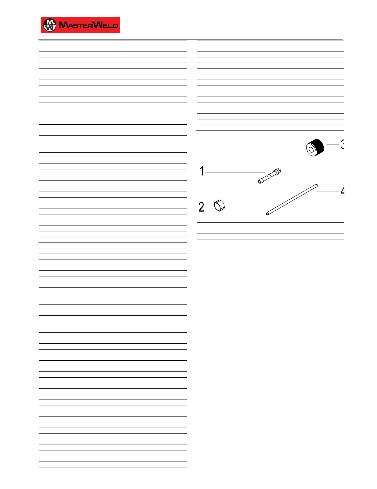
N°
CODE
DESCRIPTION
1
011.0006.0030
RIGHT HANDLE
2
040.0001.0151
KEY
3
040.0001.0150
KEY SWITCH
4
011.0016.0128
FRONT HANDLE
5
021.0001.0259
FIXED SOCKET 400 A
6
022.0002.0177
REMOTE LOGIC CABLE
7
011.0006.0029
LEFT HANDLE
8
018.0002.0004
QUICK CLUTCH
9
017.0003.0055
NIPPLE CONNECTOR
10
011.0016.0156
QUICK CLUTCH COVER PLATE
11
011.0016.0134
FRONT PLATE (1)
12
016.5001.3041
SLEEVE HOSE ADAPTER FOR RUBBER HOSE Ø= 10
mm F= 1/8 M
13
050.5071.0000
COMPLETE FRONT LOGIC PANEL
14
014.0002.0010
KNOB WITHOUT POINTER
15
014.0002.0008
KNOB WITHOUT POINTER
16
021.0001.2005
PLASTIC HOUSING
17
016.0011.0011
CAP Ø=18
18
013.0021.0549
FRONT PANEL LABEL
19
013.0000.8013
LOGIC BOARD PLATE
20
050.0001.0085
LOGIC BOARD
21
011.0016.0136
LOWER COVER
22
004.0001.0013
CASTOR
23
011.0016.0138
BASE SLIDE METAL PLATE
24
011.0016.0129
WHEEL FIXING PLATE
25
004.0001.0014
FIXED WHEEL
26
016.1000.1002
WASHER M27
27
016.0002.0005
SPLIT PIN
28
003.0002.0016
FAN
29
011.0000.0965
RIGHT COVER PANEL
30
016.0009.0005
PVC FOOT
31
011.0006.0002
PLATE SLIDE CLOSURE
32
011.0006.0008
PLASTIC HINGE
33
011.0000.0975
DOOR PLATE
34
002.0000.0268
SCREW CAP FOR SPOOL SUPPORT
35
011.0006.0052
SPOOL SUPPORT
36
011.0016.0135
REAR PLATE (1)
37
011.0016.0139
GAS BOTTLE SUPPORT PLATE
38
045.0002.0014
NEOPRENE CABLE
39
005.0001.0012
BELT FOR GAS BOTTLE
40
040.0001.0017
THREE-POLE SWITCH
41
022.0002.0190
LED WIRING
42
011.0016.0144
FRONT PLATE (2)
43
011.0016.0151
FRONT LOGIC BOARD COVER PLATE
44
015.0001.0019
HEAT SINK
45
011.0016.0147
MOTOR SUPPORT PLATE (1)
46
021.0001.2027
CAPILLARY TUBE FOR EURO CONNECTOR
47
021.0001.2000
AXIAL EURO BODY
48
021.0001.2014
BRASS GUIDE FOR EURO CONNECTOR
49
011.0016.0150
MOTOR SUPPORT PLATE (2)
50
016.1100.1200
KNURLED WASHER M12
51
021.0001.2010
CURRENT CLAMP FOR BRASS GUIDE
52
010.0008.0002
WIRE FEEDER MOTOR
53
016.2000.1219
NUT M19
54
011.0016.0153
FANS SUPPORT
55
011.0015.0029
TORCH HOLDER
56
011.0000.0935
LEFT COVER PANEL
57
012.0003.0000
INTERNAL FRAMEWORKS
58
050.0002.0091
POWER BOARD
59
050.0001.0044
SNUBBER BOARD
60
045.0006.0081
DIODE-DIODE BRACKET
61
011.0009.0121
TRANSFORMER SUPPORT PLATE
62
040.0003.1002
THERMAL CUT-OUT 75°C
63
032.0002.2003
ISOTOP DIODE
64
011.0016.0146
TUNNEL HOUSING (1)
65
050.0002.0049
MAINS FILTER BOARD
66
045.0006.0082
DIODES-SOCKET COPPER BRACKET
67
041.0004.0301
HALL EFFECT SENSOR
68
041.0006.0007
AUXILIARY TRANSFORMER
69
050.0002.0040
PRIMARY CAPACITOR BOARD
70
011.0016.0152
BOARDS SUPPORT
71
050.0003.0041
MOTOR BOARD
72
011.0016.0149
WIRE FEEDER COVER PLATE
73
050.0001.0057
POWER SUPPLY CONTROL BOARD
74
011.0016.0148
INTERNAL PLATE
75
011.0016.0140
UPPER COVER
76
011.0009.0121
TRANSFORMER SUPPORT PLATE
77
042.0003.0004
POWER TRANSFORMER
78
011.0016.0117
CABLE BUNDLE CONNECTION COVER PLATE
79
044.0004.0014
OUTPUT INDUCTOR
80
017.0001.5542
SOLENOID VALVE
81
011.0002.0018
SOLENOID VALVE PLATE
82
013.0000.7001
REAR PLATE (2)
83
045.0000.0007
CABLE CLAMP
84
016.0011.0004
FUSE HOLDER CAP
85
040.0006.1880
FUSE HOLDER
86
011.0012.0058
COOLING UNIT SUPPORT PLATE
87
022.0002.0132
C.U. POWER SUPPLY WIRING
88
021.0013.0007
C.U. POWER CONNECTOR CAP
89
011.0016.0109
PANEL SUPPORT PLATE
90
011.0016.0143
COVER PANEL SUPPORT PLATE
N°
CODE
DESCRIPTION
1
016.5001.0822
SLEEVE HOSE ADAPTER FOR RUBBER HOSE
2
016.0007.0001
HOSE CLAMP Ø=11-13
3
016.5001.0823
NUT 1/4
4
021.0001.2027
CAPILLARY TUBE
Page 24
17/03/2014 v2.2
ENGLISH
0
24/30
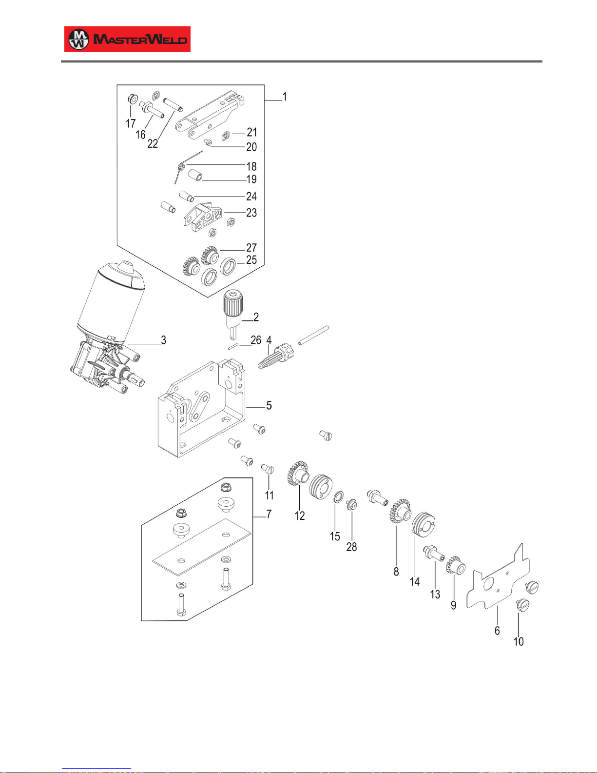
15.2 WIRE FEEDER MOTOR
Page 25
17/03/2014 v2.2
ENGLISH
0
25/30
N°
CODE
DESCRIPTION
1
002.0000.0205
COMPLETE PRESSURE ARM
2
002.0000.0203
COMPLETE PRESSURE DEVICE
3
002.0000.0201
MOTOR COIL
4
002.0000.0259
INLET GUIDE WITH SOFT LINER
5
002.0000.0202
FEED PLATE
6
002.0000.0266
GUARD SAFETY KIT
7
002.0000.0212
INSULATION MOUNTING KIT
8
002.0000.0209
GEAR ADAPTOR FEED ROLL
9
002.0000.0210
MAIN GEAR DRIVE
10
002.0000.0207
SCREW
11
002.0000.0208
SCREW
12
002.0000.0211
GEAR ADAPTOR FEED ROLL
13
002.0000.0255
SHAFT
14
002.0000.0121
FEED ROLL
15
002.0000.0270
WASHER
16
002.0000.0269
PRESSURE ARM HOLDER AXIS
17
002.0000.0271
SCREW
18
002.0000.0272
SPRING PRESSURE ARM AUTO LIFT
19
002.0000.0273
SPACE TUBE PRESSURE ARM AUTO-LIFT
20
002.0000.0274
SCREW
21
002.0000.0275
CIRCLIP
22
002.0000.0276
LOCATING PIN PRESSURE ARM
23
002.0000.0277
HOLDER
24
002.0000.0278
AXLE GAUGE
25
002.0000.0279
PRESSURE ROLL
26
002.0000.0280
LOCATING PIN PRESSURE DEVICE
27
002.0000.0281
GEAR ADAPTOR
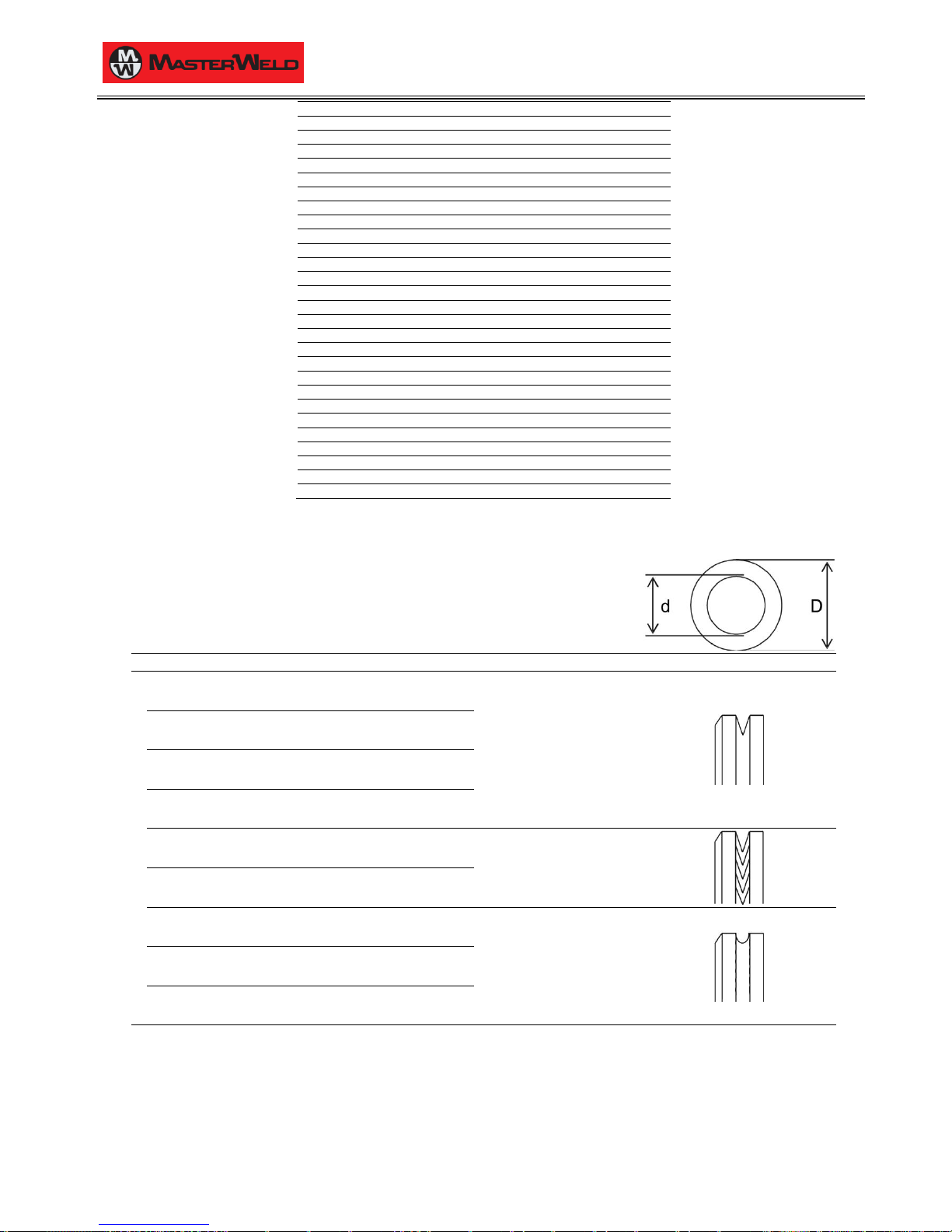
15.3 WIRE FEEDER ROLLS
D = 30 mm
d = 14 mm
N°
CODE
WIRE DIAMETER
GROOVE TYPE
14
0.6 - 0.8
002.0000.0119
V groove
Solid wire
0.8 - 1.0
002.0000.0120
1.0 - 1.2
002.0000.0121
1.2 - 1.6
002.0000.0125
1.0 - 1.2
002.0000.0124
VK shape
Flux-cored wire
1.2 - 1.6
002.0000.0127
0.8 - 1.0
002.0000.0122
U shape
Aluminium wire
1.0 - 1.2
002.0000.0123
1.2 - 1.6
002.0000.0126
Page 26
17/03/2014 v2.2
ENGLISH
0
26/30
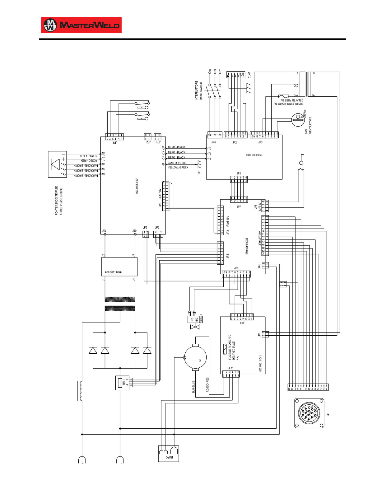
16 ELECTRICAL DIAGRAM
16.1 321 HDP
Page 27
17/03/2014 v2.2
ENGLISH
0
27/30
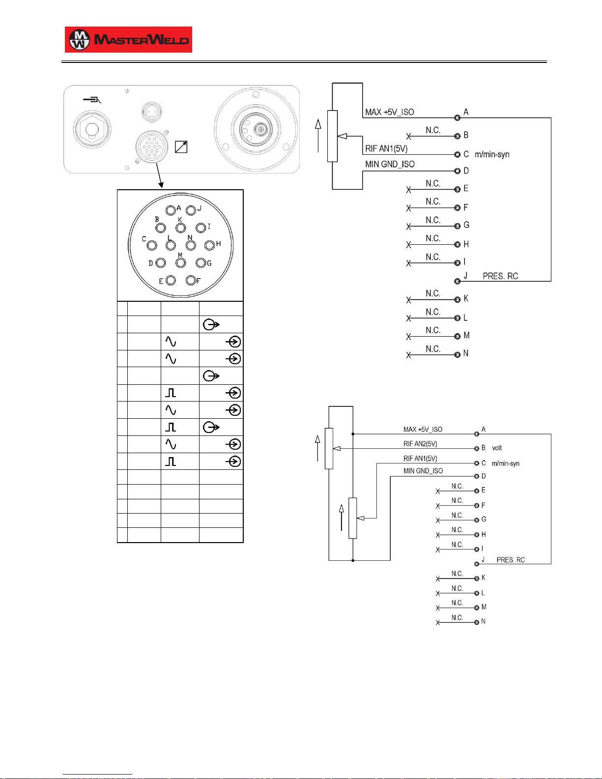
16.2 REMOTE CONTROLLER
Pin
Name
Voltage
Input/Output
A
+5 V
5 V d.c.
Out B AN2 (5 V)
0-5 V
In C
AN1 (5 V)
0-5 V
In
D
GND
GND
Out
E
D1-IN
0-5 V
In F
AN1 (10 V)
0-10 V
In G
D3-OUT
0-5 V Out H AN2 (10 V)
0-10 V
In I
D2-IN
0-5 V
In
J
RC - Not used
K - -
Not used
L - -
Not used
M - -
Not used
N - -
Not used
16.2.1 RC03: ELECTRICAL DIAGRAM
2 kOhm - 10 kOhm potentiometer
16.2.2 RC04: ELECTRICAL DIAGRAM
2 kOhm - 10 kOhm potentiometer
Page 28
17/03/2014 v2.2
ENGLISH
0
28/30
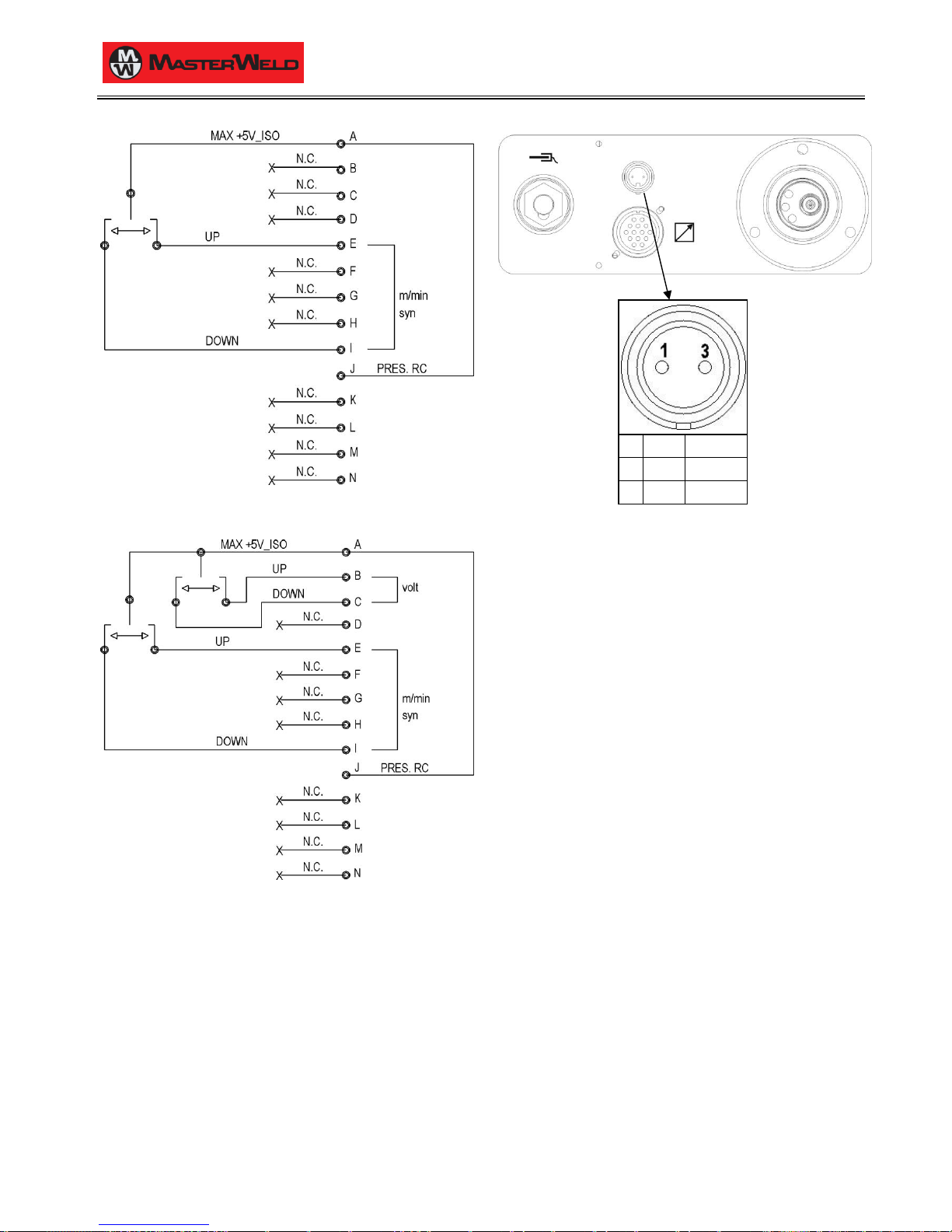
16.2.3 RC05: ELECTRICAL DIAGRAM
16.2.4 RC06: ELECTRICAL DIAGRAM
16.3 PUSH-PULL (OPTIONAL)
Pin
Name
Voltage 1 -
0 V
3 + 42 V d.c.
Page 29

17/03/2014 v2.2
ENGLISH
0
29/30
Page 30

17/03/2014 v2.2
ENGLISH
0
30/30
 Loading...