

Page 1
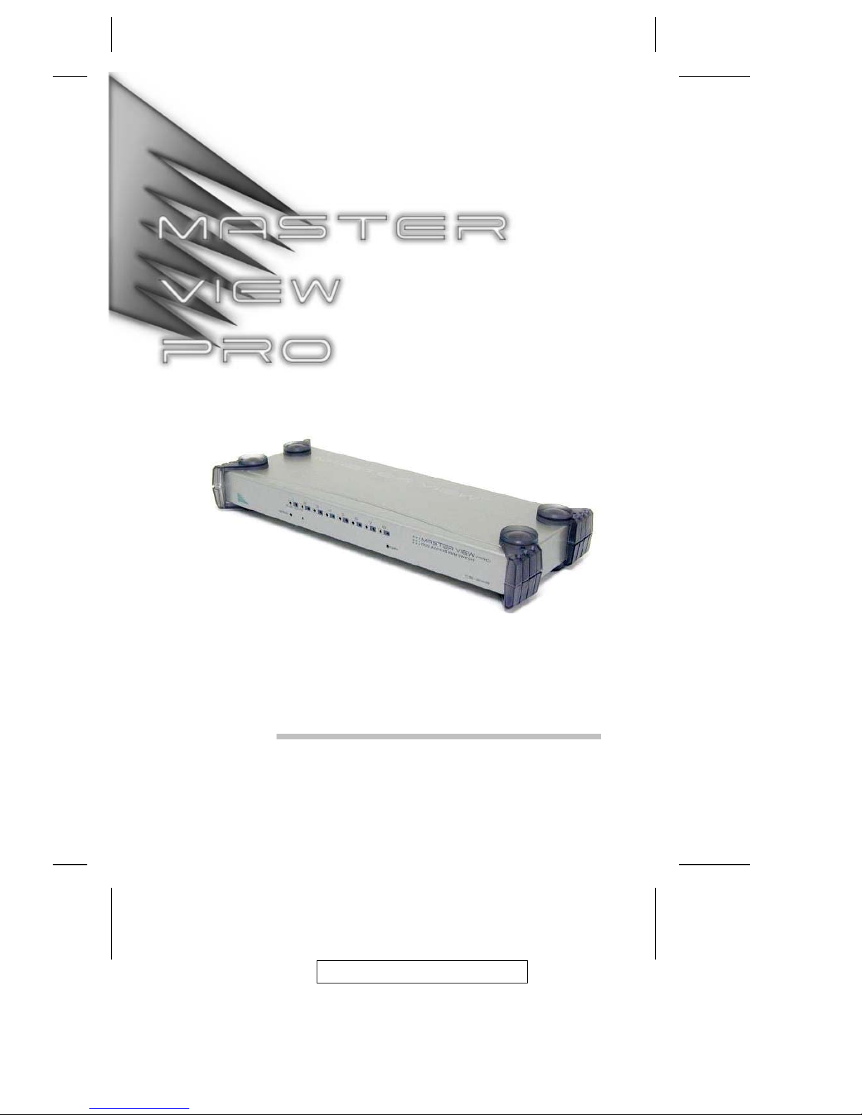
User Manual
CS-228
2005-11-29
Page 2

FCC Information
Note: This equipment has been tested and found to comply with the limits for
a Class B digital device, pursuant to Part 15 of the FCC Rules. These limits
are designed to provide reasonable protection against harmful interference in
a residential installation. This equipment generates, uses and can radiate
radio frequency energy, and if not installed and used in accordance with the
instruction manual, may cause interference to radio communications.
However, there is no guarantee that interference will not occur in a particular
installation. If this equipment does cause harmful interference to radio or
television reception, which can be determined by turning the equipment off
and on, the user is encouraged to try to correct the interference by one or
more of the following measures:
! Reorient or relocate the receiving antenna.
! Increase the separation between the equipment and receiver.
! Connect the equipment into an outlet on a circuit different from that which
the receiver is connected.
! Consult the dealer or an experienced radio/television technician for help.
All contents of this package, including products, packing materials and documentation comply with RoHS.
2005-11-29
CS-228 User Manual
ii
Page 3

User Notice
All information, documentation, and specifications contained in this manual
are subject to change without prior notification by the manufacturer. The
manufacturer makes no representations or warranties, either expressed or
implied, with respect to the contents hereof and specifically disclaims any
warranties as to merchantability or fitness for any particular purpose. Any of
the manufacturer’s software described in this manual is sold or licensed ‘as
is’. Should the programs prove defective following their purchase, the buyer
(and not the manufacturer, its distributor, or its dealer), assumes the entire
cost of all necessary servicing, repair and any incidental or consequential
damages resulting from any defect in the software.
The manufacturer of this system is not responsible for any radio and/or TV
interference caused by unauthorized modifications to this device. It is the
responsibility of the user to correct such interference.
The manufacturer is not responsible for any damage incurred in the operation
of this system if the correct operational voltage setting was not selected prior
to operation. PLEASE VERIFY THAT THE VOLTAGE SETTING IS
CORRECT BEFORE USE.
2005-11-29
CS-228 User Manual
iii
Page 4

Safety Instructions
General
! Read all of these instructions. Save them for future reference.
! Follow all warnings and instructions marked on the device.
! Do not place the device on any unstable surface (cart, stand, table, etc.). If
the device falls, serious damage will result.
! Do not use the device near water.
! Do not place the device near, or over, radiators or heat registers.
! The device cabinet is provided with slots and openings to allow for
adequate ventilation. To ensure reliable operation, and to protect against
overheating, these openings must never be blocked or covered.
! The device should never be placed on a soft surface (bed, sofa, rug, etc.)
as this will block its ventilation openings. Likewise, the device should not
be placed in a built in enclosure unless adequate ventilation has been
provided.
! Never spill liquid of any kind on the device.
! Unplug the device from the wall outlet before cleaning. Do not use liquid
or aerosol cleaners. Use a damp cloth for cleaning.
! The device should be operated from the type of power source indicated on
the marking label. If you are not sure of the type of power available,
consult your dealer or local power company.
! The device is equipped with a 3-wire grounding type plug. This is a safety
feature. If you are unable to insert the plug into the outlet, contact your
electrician to replace your obsolete outlet. Do not attempt to defeat the
purpose of the grounding-type plug. Always follow your local/national
wiring codes.
! Do not allow anything to rest on the power cord or cables. Route the
power cord and cables so that they cannot be stepped on or tripped over.
! If an extension cord is used with this device make sure that the total of the
ampere ratings of all products used on this cord does not exceed the
extension cord ampere rating. Make sure that the total of all products
plugged into the wall outlet does not exceed 15 amperes.
2005-11-29
CS-228 User Manual
iv
Page 5

! To help protect your system from sudden, transient increases and
decreases in electrical power, use a surge suppressor, line conditioner, or
un-interruptible power supply (UPS).
! Position system cables and power cables carefully; be sure that nothing
rests on any cables.
! When connecting or disconnecting power to hot-pluggable power
supplies, observe the following guidelines:
! Install the power supply before connecting the power cable to the
power supply.
! Unplug the power cable before removing the power supply.
! If the system has multiple sources of power, disconnect power from
the system by unplugging all power cables from the power supplies.
! Never push objects of any kind into or through cabinet slots. They may
touch dangerous voltage points or short out parts resulting in a risk of fire
or electrical shock.
! Do not attempt to service the device yourself. Refer all servicing to
qualified service personnel.
! If the following conditions occur, unplug the device from the wall outlet
and bring it to qualified service personnel for repair.
! The power cord or plug has become damaged or frayed.
! Liquid has been spilled into the device.
! The device has been exposed to rain or water.
! The device has been dropped, or the cabinet has been damaged.
! The device exhibits a distinct change in performance, indicating a need
for service.
! The device does not operate normally when the operating instructions
are followed.
! Only adjust those controls that are covered in the operating instructions.
Improper adjustment of other controls may result in damage that will
require extensive work by a qualified technician to repair.
2005-11-29
CS-228 User Manual
v
Page 6

Rack Mounting
! Before working on the rack, make sure that the stabilizers are secured to
the rack, extended to the floor, and that the full weight of the rack rests on
the floor. Install front and side stabilizers on a single rack or front
stabilizers for joined multiple racks before working on the rack.
! Always load the rack from the bottom up, and load the heaviest item in the
rack first.
! Make sure that the rack is level and stable before extending a device from
the rack.
! Use caution when pressing the device rail release latches and sliding a
device into or out of a rack; the slide rails can pinch your fingers.
! After a device is inserted into the rack, carefully extend the rail into a
locking position, and then slide the device into the rack.
! Do not overload the AC supply branch circuit that provides power to the
rack. The total rack load should not exceed 80 percent of the branch
circuit rating.
! Ensure that proper airflow is provided to devices in the rack.
! Do not step on or stand on any device when servicing other devices in a
rack.
2005-11-29
CS-228 User Manual
vi
Page 7

Package Contents
The complete CS-228 package consists of:
! 1 CS-228 KVM Switch with Stacking Pads
! 1 Power Adapter
! 1 Rack Mounting Kit
! 1 User Manual
Check to make sure that all the components are present and that nothing got
damaged in shipping. If you encounter a problem, contact your dealer.
Read this manual thoroughly and follow the installation and operation
procedures carefully to prevent any damage to the unit, and/or any of the
devices connected to it.
Manual Part No. PAPE-0176-1PBG
Printing Date: 11/2005
All brand names and trademarks are the registered property of their respective owners.
2005-11-29
CS-228 User Manual
vii
Page 8

Contents
FCC Information . . . . . . . . . . . . . . . . . . . . . . . . . . . . ii
User Notice . . . . . . . . . . . . . . . . . . . . . . . . . . . . . . . iii
Safety Instructions . . . . . . . . . . . . . . . . . . . . . . . . . . . . iv
General . . . . . . . . . . . . . . . . . . . . . . . . . . . . . . . iv
Rack Mounting . . . . . . . . . . . . . . . . . . . . . . . . . . . vi
Package Contents . . . . . . . . . . . . . . . . . . . . . . . . . . . . vii
About This Manual . . . . . . . . . . . . . . . . . . . . . . . . . . . . x
Overview . . . . . . . . . . . . . . . . . . . . . . . . . . . . . . . x
Conventions . . . . . . . . . . . . . . . . . . . . . . . . . . . . . . x
Chapter 1
Introduction
Overview . . . . . . . . . . . . . . . . . . . . . . . . . . . . . . . . . 1
Features . . . . . . . . . . . . . . . . . . . . . . . . . . . . . . . . . . 2
Hardware Requirements . . . . . . . . . . . . . . . . . . . . . . . . . . 3
Consoles . . . . . . . . . . . . . . . . . . . . . . . . . . . . . . . . 3
Computers . . . . . . . . . . . . . . . . . . . . . . . . . . . . . . . 3
Cables . . . . . . . . . . . . . . . . . . . . . . . . . . . . . . . . . 4
Front View . . . . . . . . . . . . . . . . . . . . . . . . . . . . . . . . . 5
Rear View . . . . . . . . . . . . . . . . . . . . . . . . . . . . . . . . . 6
Chapter 2
Hardware Setup
Before You Begin . . . . . . . . . . . . . . . . . . . . . . . . . . . . . 7
Stacking and Rack Mounting . . . . . . . . . . . . . . . . . . . . . . . 7
Stacking . . . . . . . . . . . . . . . . . . . . . . . . . . . . . . . . 7
Rack Mounting . . . . . . . . . . . . . . . . . . . . . . . . . . . . 8
Single Stage Installation . . . . . . . . . . . . . . . . . . . . . . . . . . 9
Two Stage Installation . . . . . . . . . . . . . . . . . . . . . . . . . . 11
Basic Operation . . . . . . . . . . . . . . . . . . . . . . . . . . . . . 13
Hot Plugging . . . . . . . . . . . . . . . . . . . . . . . . . . . . 13
Powering Off and Restarting . . . . . . . . . . . . . . . . . . . . 14
Port Selection . . . . . . . . . . . . . . . . . . . . . . . . . . . . 14
2005-11-29
CS-228 User Manual
viii
Page 9

Chapter 3
OSD Operation
OSD Overview . . . . . . . . . . . . . . . . . . . . . . . . . . . . . 15
Port Numbering . . . . . . . . . . . . . . . . . . . . . . . . . . . . . 16
OSD Main Menu Headings . . . . . . . . . . . . . . . . . . . . . . . 16
OSD Navigation . . . . . . . . . . . . . . . . . . . . . . . . . . . . . 17
OSD Functions . . . . . . . . . . . . . . . . . . . . . . . . . . . . . 18
F1 HELP . . . . . . . . . . . . . . . . . . . . . . . . . . . . . . 18
F2 EDIT . . . . . . . . . . . . . . . . . . . . . . . . . . . . . . . 19
F3 LIST . . . . . . . . . . . . . . . . . . . . . . . . . . . . . . . 20
F4 SCAN . . . . . . . . . . . . . . . . . . . . . . . . . . . . . . 21
F5 ADM . . . . . . . . . . . . . . . . . . . . . . . . . . . . . . . 22
F6 SET . . . . . . . . . . . . . . . . . . . . . . . . . . . . . . . 23
F7 QV . . . . . . . . . . . . . . . . . . . . . . . . . . . . . . . . 25
Appendix
Computer Connection Tables . . . . . . . . . . . . . . . . . . . . . . 27
Specifications . . . . . . . . . . . . . . . . . . . . . . . . . . . . . . 28
OSD Factory Default Settings . . . . . . . . . . . . . . . . . . . . . . 29
Troubleshooting . . . . . . . . . . . . . . . . . . . . . . . . . . . . . 29
Limited Warranty . . . . . . . . . . . . . . . . . . . . . . . . . . . . 30
2005-11-29
CS-228 User Manual
ix
Page 10

About This Manual
This User Manual is provided to help you get the most from your CS-228
system. It covers all aspects of installation, configuration and operation. An
overview of the information found in the manual is provided below.
Overview
Chapter 1, Introduction, introduces you to the CS-228 System. Its purpose,
features and benefits are presented, and its front and back panel components are
described.
Chapter 2, Installation, describes stacking and rack mounting, how to set up
a single or multiple stage installation, and the basic operation of the CS-228.
Chapter 3, OSD Operation, provides a complete description of the
CS-228’s OSD (On Screen Display), and how to work with it.
An Appendix at the end of the manual provides specifications and other
technical information regarding the CS-228.
Conventions
This manual uses the following typographical conventions:
Courier
Indicates text that you should key in.
[ ]
Indicates keys you should press. For example, [Enter] means
to press the Enter key. If keys need to be chorded, they
appear together in the same bracket with a plus sign between
them: [Ctrl+Alt].
1.
Numbered lists represent procedures with sequential steps.
!
Bullet lists provide information, but do not involve sequential
steps.
→
Indicates movement through a series. For example, Start →
Run means to open the Start menu, and then select Run.
Indicates critical information.
2005-11-29
CS-228 User Manual
x
Page 11

Chapter 1.
Introduction
Overview
The CS-228 KVM Switch is a control unit that allows two independent
keyboard, mouse, and monitor consoles to access eight computers, either
independently or on a multi-user shared basis. A CS-228 can control up to 8
computers directly. By cascading it down to a CS-138A, CS-9138, CS-128A,
or CS-124A, up to 9 units (the CS-228 plus eight cascaded ones), can control
up to 64 computers.
Setup is fast and easy - plugging cables into their appropriate ports is all that
is entailed. There are no installation routines or complex software programs
to configure. Because the CS-228 intercepts keyboard input directly, it works
on most hardware platforms and with most operating systems.
The CS-228 provides a convenient OSD (On Screen Display) function that
allows either of the two consoles to access any computer connected to the
system by means of an on screen, menu-driven interface. A powerful Quick
View Scan feature allows auto scanning and monitoring of the activities of all
operating computers on the installation one-by-one.
For security, two level password protection (administrator and user), prevents
unauthorized access to the computers. Responding to the growing use of
audio input/output in the workstation space, the CS-228 has been designed
with built in microphone and speaker support, as well.
There is no better way to save time and money than with a CS-228
installation. By allowing all the computers to be managed from two separate
consoles, a CS-228 installation: (1) eliminates the expense of having to
purchase a separate keyboard, monitor, and mouse for each computer; (2)
saves all the space those extra components would take up; (3) saves on
energy costs; and (4) eliminates the inconvenience and wasted effort
involved in constantly moving around from one computer to another, while
allowing a single user to access the computers from several different
convenient locations, or for two users to share them.
2005-11-29
1
Page 12

Features
! 2 Consoles Control 8 Computers
! One or Two Users Can Operate Up To 64 Computers (via cascade to
CS-138A, CS-9138, CS-128A, or CS-124A) At The Same Time
! Each Console Has Its Own Access Control
! Port Selection via OSD (On Screen Display)
! Auto Expansion of The OSD Port List For Cascaded Installations
! OSD Automatically Adjusts to Resolution Changes
! Hot Pluggable - Add or Remove any Computer without Powering Off the
Switch
! Auto Scan Function Provides Easy Monitoring of All Computers
! Supports 1920 x 1440 Resolution; DDC2 (Display Data Channel 2)
! PS/2 Compatible Mouse Support: Microsoft Intellimouse Pro, Logitech
FirstMouse, FirstMouse+, Support*
! Audio (Microphone and Speaker) Support
! Special Design For Easy Stacking
* 1. PS/2 compatible mouse support is for three button (wheel) mice
2. The Logitech Mouse Ware program’s Change Device procedure
does not work on Microsoft NT systems.
2005-11-29
CS-228 User Manual
2
Page 13

Hardware Requirements
Consoles
! A VGA, SVGA, or Multisync monitor capable of the highest resolution
that you will be using on any computer in the installation.
Note: If a monitor switches to a computer using a resolution that is
higher than the resolution that the monitor can support, serious
damage to the monitor may result.
! A PS/2 style mouse
! A PS/2 style keyboard
! Microphone and Speakers (Optional)
Computers
The following equipment must be installed on each computer:
! A VGA, SVGA or Multisync card
! Either a 6-pin mini-DIN (PS/2 style), or DB-9 (standard serial), mouse port.
! Either a 6-pin mini-DIN (PS/2 style) keyboard port with +5V DC on pin 4
and Ground on pin 3, or a 5-pin DIN (AT style) keyboard port with +5V
DC on pin 5 and ground on pin 4
2005-11-29
1. Introduction
3
Page 14
Cables
Use of substandard cables may damage the connected devices or degrade
overall performance. For optimum signal integrity and to simplify the layout,
we strongly recommend that you use the following high quality CS Custom
Cable sets:
Cable Type Length Part Number
PS/2 KVM 1.8m 2L-1701P
PS/2 KVM 3m 2L-1703P
PS/2 KVM 5m 2L-1705P
PS/2 KVM 10m 2L-1710P
Note: 1. If your computer uses a standard AT style keyboard socket you will
need to purchase a PS/2-to-AT keyboard adapter in order to plug
the cable into the computer’s keyboard port.
2. If your computer uses a standard 9 pin serial port for the mouse,
you will need to purchase a PS/2-to-Serial mouse adapter in order
to plug the cable into the computer’s serial port.
2005-11-29
CS-228 User Manual
4
Page 15
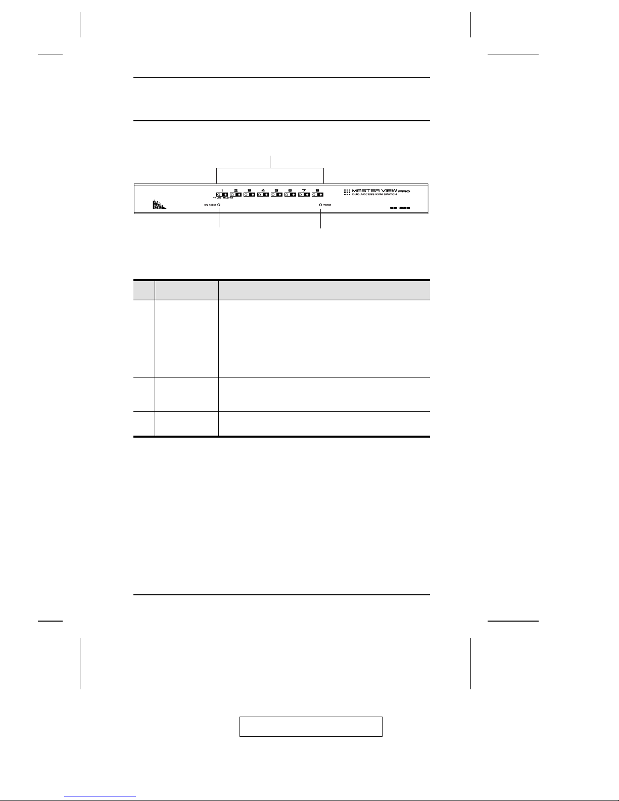
Front View
No.
Component Description
1
Port LEDs ! An On Line LED lights ORANGE to indicate that the
computer attached to its corresponding port is up and
running. If the LED is flashing, it indicates that the Port is
being used for Cascading to another switch.
! A Selected LED lights GREEN to indicate that the
computer attached to its corresponding port is the one
that has the KVM focus.
2
K/M Reset If the keyboard and mouse get stuck and need to be reset,
press this semi-recessed switch in with a thin object, such
as a paper clip or a ballpoint pen.
3
Power LED Lights BLUE to indicate that the unit is turned on and
receiving power.
1
2
3
2005-11-29
1. Introduction
5
Page 16
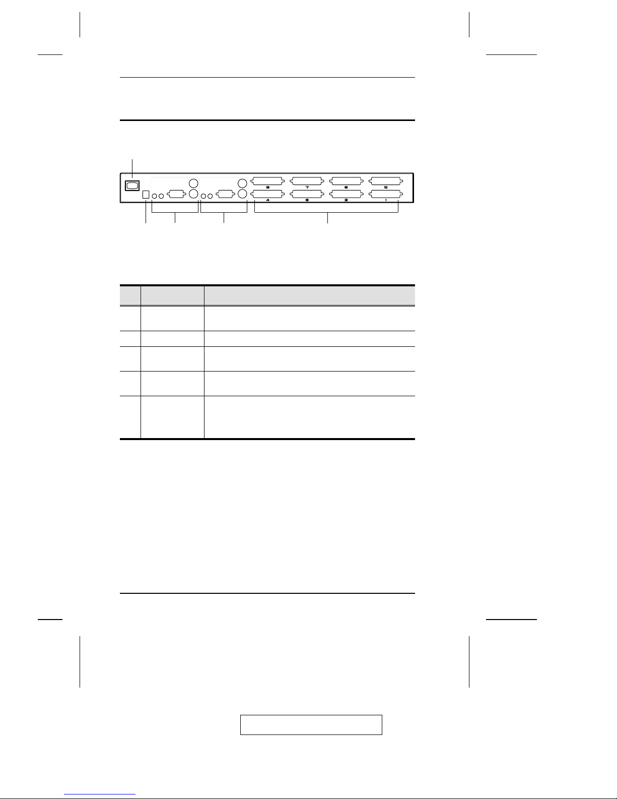
Rear View
No.
Component Description
1
Power Switch This is a standard rocker switch that powers the unit On
and Off.
2
Power Jack The power adapter cable plugs in here.
3
Console 2
Section
The microphone, speakers, monitor, keyboard and mouse
that belong to Console 2 plug in here.
4
Console 1
Section
The microphone, speakers, monitor, keyboard and mouse
that belong to Console 1 plug in here.
5
KVM Port
Section
Use CS Custom Cables (as specified in the Cables section
on p. 4), to connect any available port to the computers you
are installing, or to cascade second stage CS-228 KVM
switches.
1
3 42 5
2005-11-29
CS-228 User Manual
6
Page 17

Chapter 2.
Hardware Setup
Before You Begin
Stacking and Rack Mounting
Stacking
1. The unit comes with the stacking brackets already attached. Note that
there is a top and bottom half to each bracket. The top half has a convex
surface; the bottom half has a concave surface.
2. Line up the four bottom brackets of the top unit with the four top brackets
of the bottom unit; then fit the top unit down onto the bottom unit.
1. Important safety information regarding the placement of this
device is provided on p. iv. Please review it before proceeding.
2. Make sure that power to all the devices you will be connecting
up have been turned off. You must unplug the power cords of
any computers that have the Keyboard Power On function.
2005-11-29
7
Page 18
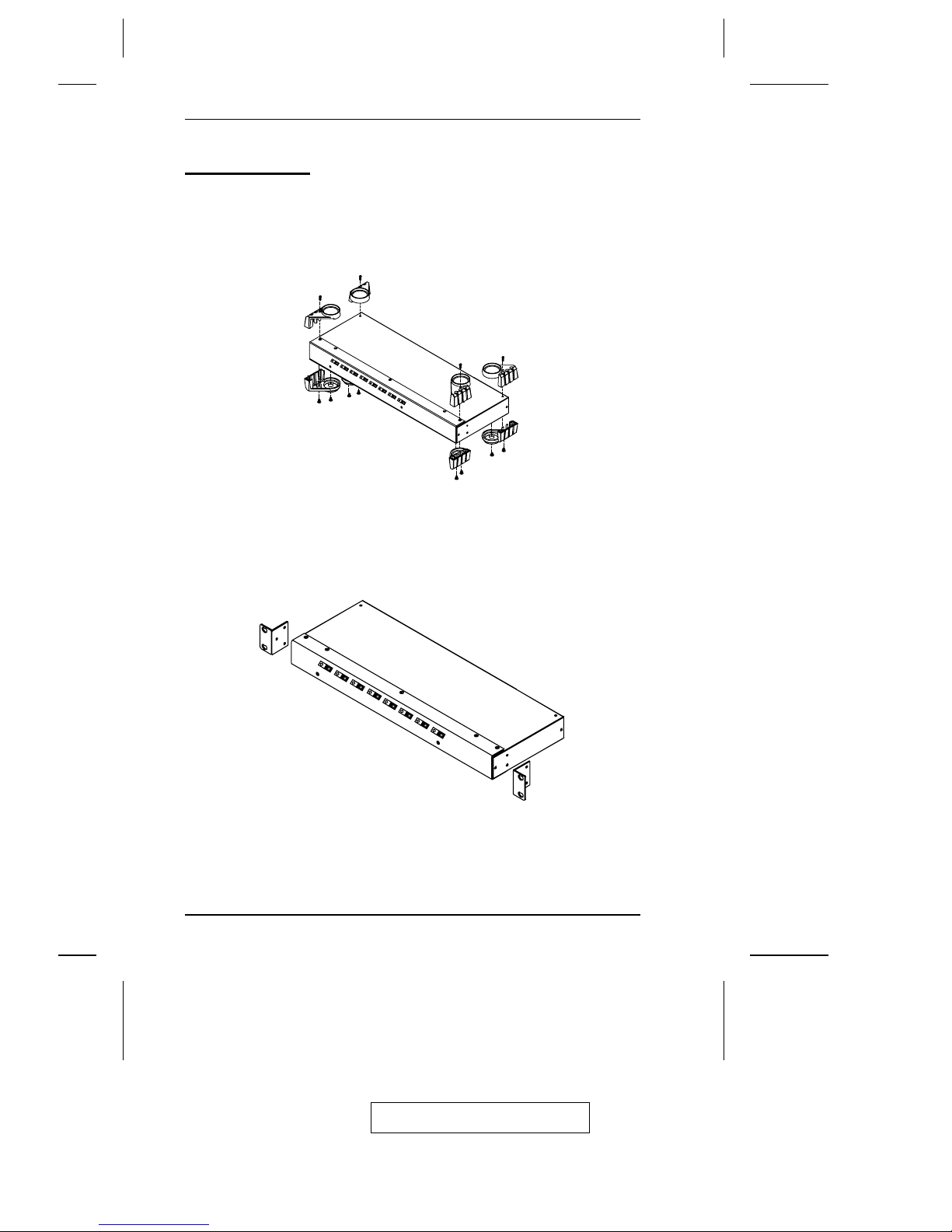
Rack Mounting
To rack mount the unit do the following:
1. First remove the stacking brackets by unscrewing them from the unit, as
shown in the diagram below:
2. Screw the mounting brackets into the sides of the unit, as shown in the
diagram below
3. Slide the unit into the rack and secure it to the rack.
2005-11-29
CS-228 User Manual
8
Page 19

Single Stage Installation
The most basic installation is a Single Stage installation, in which no
additional switches are cascaded down from the first unit. To set up a single
stage installation, refer to the diagram on the next page do the following:
1. Plug the monitor, keyboard, and mouse cables for Consoles 1 and 2 into
the port connectors located on the rear panel of the CS-228 unit. Each port
is labeled with an appropriate icon to indicate itself.
2. Plug the microphone and speaker cables (if you are using them), for
Consoles 1 and 2 into the port connectors located on the rear panel of the
CS-228 unit. Each port is labeled with an appropriate icon to indicate
itself.
3. Use PS/2 KVM cables (as described in the Cables section on p. 4), to
connect the monitor, keyboard and mouse ports of the computers to any
available CS-228 KVM Port.
4. Plug the power adapter into an AC power source; plug the power adapter
cable into the CS-228’s Power Jack.
5. Turn on the power to the CS-228.
Note: When you turn the unit on, it undergoes a Power On Self-Test. If
there is a problem, the On Line Port LEDs flash repeatedly
according to a pattern that indicates what the problem is:
Pattern Indication
On Line LEDs 1 - 8 Flash Simultaneously Internal RAM Memory Error
On Line LEDs 1 - 8 Flash One After the Other External RAM Memory Error
On Line LED pairs 1+2, 3+4, 5+6, and 7+8
Flash One After the Other
ROM Test Error
If any of these problems occur, turn the Switch Off, then turn it on again.
(continues on next page)
2005-11-29
2. Hardware Setup
9
Page 20
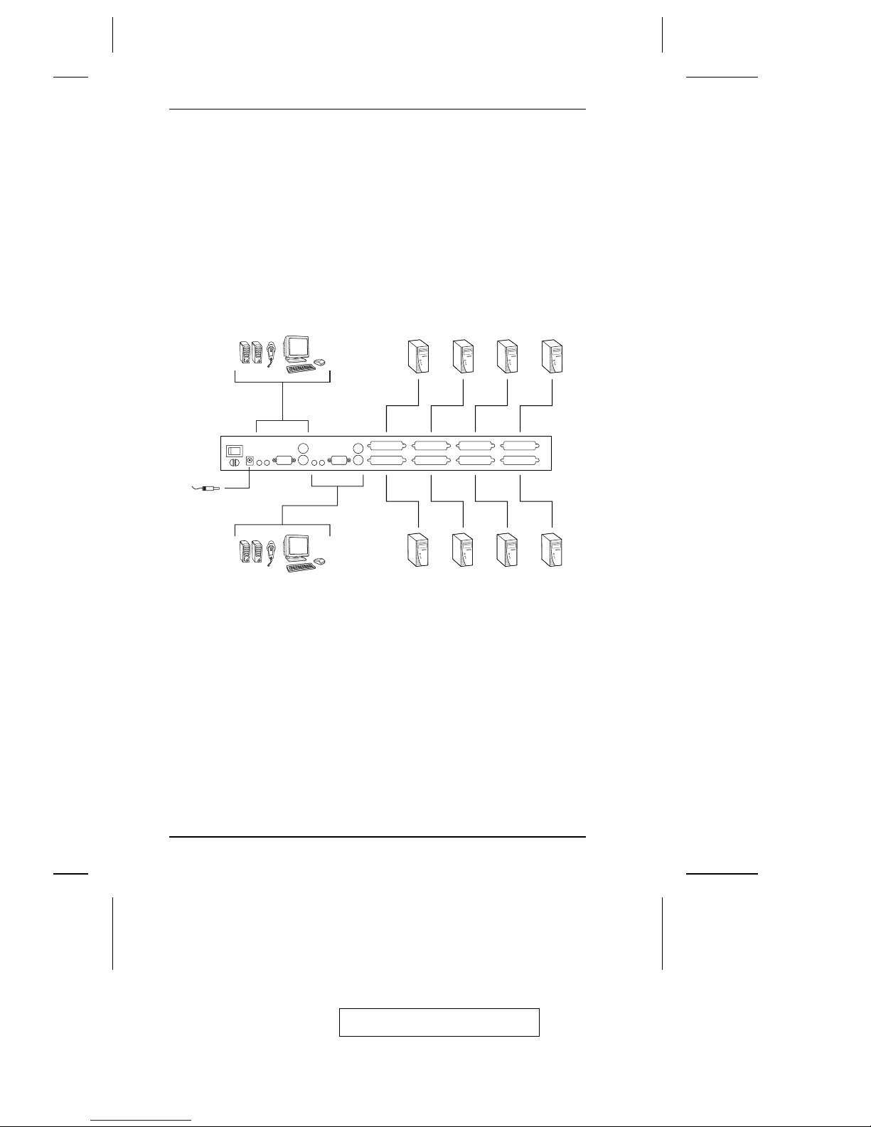
6. Plug in the power cords and power on all the computers.
Note: You must turn on the power to the CS-228 before turning on the
power to the computers.
2005-11-29
CS-228 User Manual
10
Page 21

Two Stage Installation
To control even more computers, up to eight additional switches can be
cascaded from the CPU ports of the CS-228. The cascaded switches that
connect back to the First Stage unit (the CS-228), are considered Second
Stage units. As many as 64 computers can be controlled in a complete two
stage installation. A table showing the relation between the number of
computers and the number of switches needed to control them is provided in
the Appendix.
Note: 1. Only CS-138A, CS-9138, CS-128A, or CS-124A units can be used
with the CS-228;
2. The CS-228 does not support cascading beyond the second stage.
To set up a two stage installation, refer to the diagram on the next page and
do the following:
1. Make sure that power to all the devices you will be connecting up has
been turned off (unplug the power cords of any computers that have the
Keyboard Power On function).
2. Follow steps 1 and 2 under Single Stage Installation (see p. 9).
3. Use a PS/2 KVM cable (described in the Cables section, p. 4) to connect
any available CPU port on the CS-228 to the console port on the Second
Stage unit.
Repeat step 3 for any additional switches that you wish to cascade.
4. Use PS/2 KVM cables (described in the Cables section, p. 4) to connect
any available CPU port(s) on the Second Stage unit(s) to the monitor,
keyboard and mouse ports of the computer(s) you are installing.
5. Plug in the power adapter cables for all switches on the installation.
6. Power on the First Stage CS-228.
7. Power on all Second Stage units.
8. Plug in the power cords and power on all the computers.
2005-11-29
2. Hardware Setup
11
Page 22
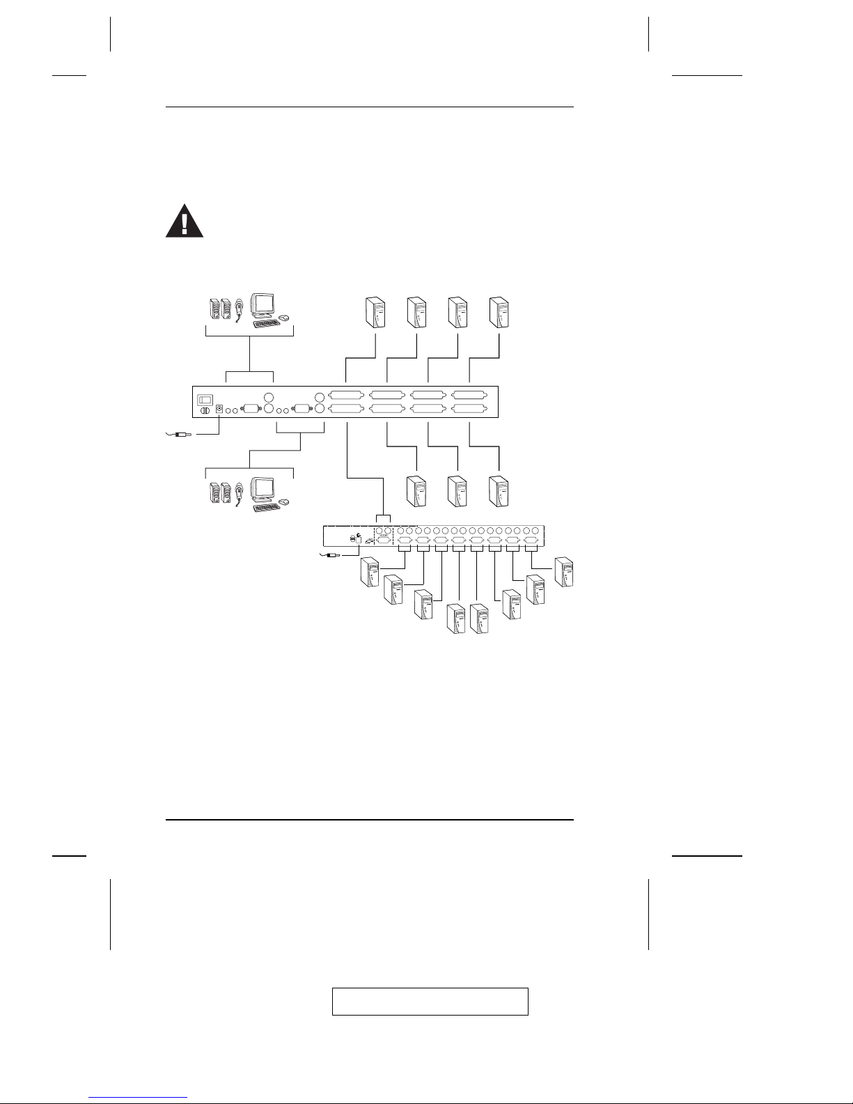
You must follow the sequence in steps 5 - 8 when powering up.
12345678
2005-11-29
CS-228 User Manual
12
Page 23

Basic Operation
Hot Plugging
The CS-228 supports hot plugging - components can be removed and added
back into the installation by unplugging their cables from the CPU ports
without the need to shut the unit down. In order for hot plugging to work
properly, however, these procedures must be followed:
1. When hot plugging cables from the CPU ports the cable must be plugged
back into the same port it was removed from.
2. You may unplug the mouse and plug it back in again (to reset the mouse,
for example), as long as you use the same mouse.
If there is no response to the mouse and/or keyboard after you plug the
mouse back in, perform a K/M Reset. To do so, insert a thin pointed object
into the Reset receptacle on the unit’s front panel and gently push.
2005-11-29
2. Hardware Setup
13
Page 24

Powering Off and Restarting
If it becomes necessary to Power Off the CS-228, before restarting it you
must do the following:
1. Shut down all the computers on the CS-228 installation (includes those
connected to cascaded switches).
Note: You must unplug the power cords of any computers that have the
Keyboard Power On function. Otherwise, the switches will still
receive power from the computers.
2. Wait 10 seconds, and then restart the CS-228.
Note: When the CS-228 comes up it issues a long beep, and the
Consoles are automatically logged out. Each Console logout
produces a short beep - so you will hear one long and two short
beeps.
3. Restart the Second Stage switches.
4. After all the switches are up, power On the computers.
Port Selection
Instant access to any computer on the installation is provided by the menu
driven On Screen Display (OSD) function. OSD operation is discussed in the
next chapter.
2005-11-29
CS-228 User Manual
14
Page 25
Chapter 3.
OSD Operation
OSD Overview
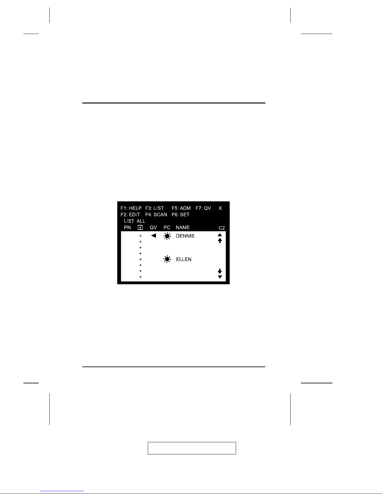
The On Screen Display (OSD) provides a menu driven interface to handle
the computer switching procedure. All operations start from the OSD Main
Menu. To activate the Main Menu, tap a [Ctrl] key twice.
Note: 1. You must tap the same key twice (both left, or both right).
2. If using the [Ctrl] key conflicts with applications running on the
computers, you can change the OSD activation key to the Scroll
Lock key (see OSD Activating Hotkey under the F6 Set function on
p. 23), in which case you would press [Scroll Lock] twice.
When you invoke the OSD, a screen similar to the one below appears:
! The OSD always starts in List view, with the highlight bar at the same
position it was in the last time it was closed.
! The Port Number (PN) for each computer on the installation is shown in
the left column of the list. Port numbering details are discussed in the next
section.
1-5
1-6
1-7
1-8
2-1
2-2
2-3
2-4
2005-11-29
15
Page 26

Port Numbering
The Port Number (PN) for a computer connected to the CS-228 is derived
from the KVM Port (1 - 8) on the CS-228’s back panel that the computer is
connected to. A computer connected to KVM Port 7, for example, would
have a PN of 7.
A computer connected to a cascaded CS-228 has a two digit PN. The first
digit represents the KVM Port of the CS-228 (the First Stage unit) that the
Second Stage CS-228 is cascaded down from; the second digit represents the
KVM Port of the Second Stage CS-228 that the computer is connected to.
For example, a computer connected to KVM Port 3 of a CS-228 that is
cascaded down from KVM Port 2 of a CS-228, would have a PN of 2-3.
OSD Main Menu Headings
Heading Explanation
PN
This column lists the Port Numbers for all the KVM Ports. The simplest
method to access a particular computer (assuming you know which
port it is attached to), is to double-click it with the mouse; or to use the
navigation keys to move the highlight bar to it, and then press
[Enter] .
Indicates ports that this Console can access.
QV
An arrowhead symbol in this column indicates the Port has been
selected for Quick View Scan Mode (see F7, p. 25).
PC
A sun symbol in this column indicates that the computer connected to
this Port is powered On, and is On Line.
NAME
If a port has been given a name (see F2, p. 19), its name appears in
this column.
+
2005-11-29
CS-228 User Manual
16
Page 27

OSD Navigation
! To dismiss the menu, and deactivate the OSD, Click the X at the upper
right corner of the OSD Window; or press [Esc].
! To move up or down through the list one line at a time, Click the Up and
Down Triangle symbols (
!"), or use the Up and Down Arrow Keys. If
there are more items than appear on the screen, the screen will scroll.
! To move up or down through the list one screen at a time, Click the Up
and Down Arrow symbols ("#), or use the [Pg Up] and [Pg Dn] keys. If
there are more items than appear on the screen, the screen will scroll.
! To access a port, double-click it (or move the highlight bar to it), and then
press [Enter].
Note: 1. If you try to access a computer that has been designated as
private (see Private Mode, p. 24), a message appears to inform
you that the Port is in Private Mode. In this case, the screen is
blank, and the port can neither be viewed nor accessed.
2. If you try to access a computer that is already being accessed
by another Console, a message displays to inform you that the
Port is In Use. The target computer’s screen can be viewed, but
you cannot give it any input until the Console that already has
control stops accessing it.
3. In a cascaded installation, if a computer attached to a Second
Stage unit is already being accessed by the other Console, that
computer and all the other computers attached to the same
Second Stage unit are considered to be in use. None of them
can be viewed or accessed from your Console. This is so,
because accessing any one computer attached to a Second
Stage unit ties up the entire CS-228 Port that their Second Stage
unit is cascaded down from. Only after the original Console no
longer has access can these computers be controlled from the
other Console.
! After executing any action, you automatically go back to the menu one
level above.
2005-11-29
3. OSD Operation
17
Page 28

OSD Functions
OSD functions are used to configure and control the OSD. For example, you
can: rapidly switch to any port; scan selected ports only; limit the list you
wish to view; designate a port for Quick View scanning; create or edit a port
name; or make OSD setting adjustments.
To access an OSD function:
1. Either click a function key field on the screen, or press a function key on
the keyboard.
2. In the submenus that appear, make your choice either by double-clicking
it, or moving the highlight bar to it.
3. Press [Esc] to activate your choice and return to the previous menu level.
F1 HELP
Help provides a quick guide to OSD operation. To return to the OSD Main
Menu, Click the X at the upper right corner of the OSD Window; or press
[Esc].
2005-11-29
CS-228 User Manual
18
Page 29

F2 EDIT
To help remember which computer is attached to a particular port, every port
can be given a name. The Edit function allows the Administrator to create,
modify, or delete port names. To Edit a port name:
1. Click the port you want, or use the navigation keys to move the highlight
bar to it.
2. Click the F2 field, or Press [F2].
3. Key in the new Port Name, or modify/delete the old one.
The maximum number of characters allowed for the Port Name is 15.
Legal characters include:
! All alpha characters: a - z; A - Z
! All numeric characters: 0 - 9
! +, -, /, :, ., and Space
Case does not matter; OSD displays the Port Name in all capitals no
matter how they were keyed in.
4. When you have finished editing, press [Enter] to have the change take
effect. To abort the change, press [Esc].
2005-11-29
3. OSD Operation
19
Page 30
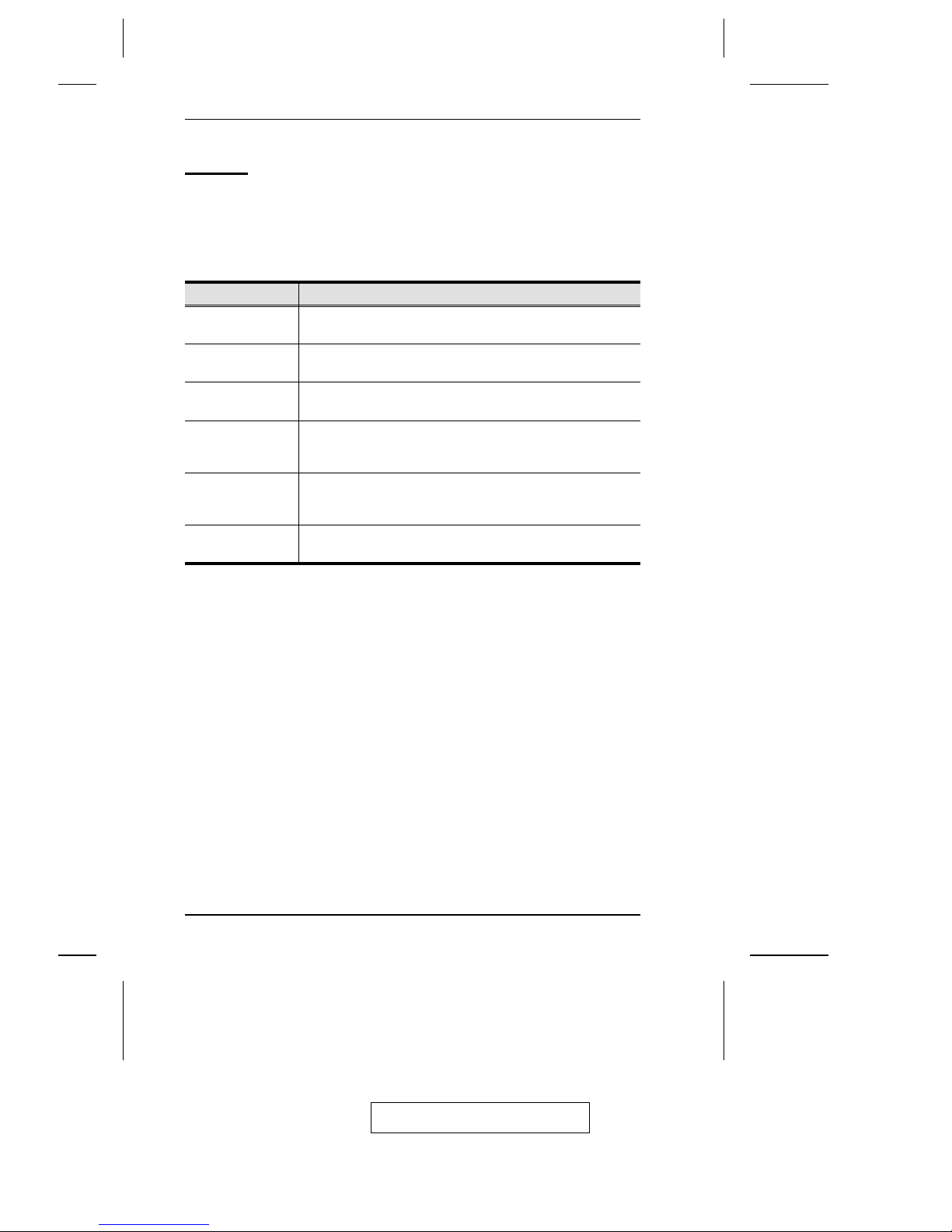
F3 LIST
This function lets you broaden or narrow the scope of which ports the OSD
lists. This will be different for each Console, depending on the choices made
for that Console. The choices and their meanings are given in the table below:
Choice Meaning
ALL Lists the Port Numbers and Names (if names have been
specified - see F2 on p. 19), of all the ports on the installation.
QVIEW Lists only the ports that have been selected for Quick View
scanning (see F7 on p. 25).
POWERED ON Lists only the ports that have their attached computers
Powered On.
POWERED ON +
QVIEW
Lists only the ports that have been selected for Quick View
scanning (see F4 on p. 21), and that have their attached
computers Powered On.
QVIEW + NAME Lists only the ports that have been selected for Quick View
scanning (see F7 on p. 25), and have been assigned names
(see F2 on p. 19).
NAME Lists only the ports that have been assigned names (see F2 on
p. 19).
Double-click the choice you want, or move the highlight bar to it, and then
press [Enter]. An icon appears before the choice to indicate that it is the
currently selected one.
Note: 1. You can access any port on any list by double-clicking it, or using
the navigation keys, and then pressing [Enter].
2. If you select a port that does not have a computer attached to it, or
if the attached computer is powered Off, the OSD will still switch
to it, and will not show an error. To recover, press the OSD
Activation Hotkey.
2005-11-29
CS-228 User Manual
20
Page 31

F4 SCAN
Clicking the F4 field, or pressing [F4] initiates Scan Mode, in which the OSD
cycles through all the ports that have been selected for scanning with the Scan
Mode setting (see p. 24). When you want to stop at a particular location, press
the [Spacebar] to stop scanning.
Note: 1. If the scanning stops on an empty port, or one where the computer
is attached but is powered Off, the monitor screen will be blank and
the mouse and keyboard will have no effect. To recover, press the
OSD Activation Hotkey.
2. As the OSD cycles through the selected ports, an S appears in front
of each accessed computer’s Port ID display to indicate that the
computer is being accessed under Quick View Scanning.
3. If a particular port is being accessed by another Console, an R
appears in front of the Port ID display to indicate that the Port is
"View Only." It can be viewed, but cannot be accessed at this time.
4. If a particular port has been designated as private (see F6 on p. 23),
a P appears in front of the Port ID display to indicate that the Port
is in "Private Mode." The screen is blank, and the port can neither
be viewed nor accessed.
5. If a particular port was accessed by one of the Consoles, but is no
longer being accessed, the OSD begins a Timeout countdown (see
Set Access Timeout p. 22), a Z appears in front of the Port ID
display to indicate that the Port is Pending (i.e., the original
Console that accessed can still reclaim it, but if it doesn’t access the
Port before the Timeout period ends, it is up for grabs to the first
comer).
2005-11-29
3. OSD Operation
21
Page 32

F5 ADM
F5 allows configuration of the OSD operation of the Console. To change a
setting double-click it; or use the up and down arrow keys to move the
highlight bar to it, and then press [Enter].
After you select an item, a submenu with further choices for you to select
from appears. Double-click the choice you want, or move the highlight bar to
it, and then press [Enter]. An icon appears before the selected choice so that
you know which one it is. The settings are explained in the following table:
Setting Function
SET ACCESS
TIMEOUT
This function is used to set the timeout value to control the
release of access rights to a computer. If the original
Console doesn’t access the computer before the timeout
value is reached, the computer becomes available to the
other Console. To set the timeout value, key in a number
from 1 - 255 seconds, and then press [Enter]. If the
number is 0, this function is disabled. The default is 2
seconds.
CLEAR THE NAME
LIST
This function is used to undo all Administrator changes
and return the setup to the original factory default settings.
Note: While this function is in progress, make sure that no
other operations are performed on either Console.
RESTORE DEFAULT
VALUES
This function is used to undo all Administrator changes
and return the setup to the original factory default settings except for the Names that were assigned to Ports, which
are saved.
RELEASE ALL
PRIVATE
Releases all Ports that have been set to Private Mode (see
Private Mode, p. 24), so that they become accessible to all
Consoles.
2005-11-29
CS-228 User Manual
22
Page 33

F6 SET
F6 allows you to configure the OSD settings for the Console you are working
at. To change a setting:
1. Double-click it, or move the highlight bar to it, and then press [Enter].
2. Press [Esc] to activate it.
After you select an item, a submenu with further choices appears. To make a
selection, either double-click it; or move the highlight bar to it, and then
press [Enter]. An icon appears before the selected choice to indicate which
one it is. The settings are explained in the table below:
Setting Function
OSD ACTIVATING
HOTKEY
Selects which Hotkey activates the OSD function: [Ctrl]
[Ctrl] (the default) or [Scroll Lock] [Scroll Lock]. The
Scroll Lock option is provided in case the Ctrl key
combination conflicts with programs running on the
computers.
CHANNEL DISPLAY
MODE
Selects how the Port ID is displayed: the Port Number plus
the Name (PN + NAME); the Port Number alone (PN); or
the Name alone (NAME).
CHANNEL DISPLAY
DURATION
Determines the length of time a Port ID is displayed after a
port change has taken place. The choices are: User
Defined - which lets you select the amount of time that the
Port ID displays for after a port change has taken place
(from 1 - 255 sec.); and Display Always On - which
displays the Port ID at all times. If you select User Defined,
key in the number of seconds, and then press [Enter]. The
default is 3 Seconds.
CHANNEL DISPLAY
POSITION
Allows you to position where the Port ID appears on the
screen. Highlight this item, and then press [Enter]. Use the
Mouse or the arrow keys to position the Port ID display, and
then double-click or press [Enter] to lock the position and
return to the Set submenu.
(continues on next page)
2005-11-29
3. OSD Operation
23
Page 34

Setting Function
SCAN MODE Selects which Ports are available for scanning. There are
six choices:
ALL - All the Ports which have been set Accessible (see F5
on p. 22);
QVIEW - Only those Ports which have been set Accessible
(see F5 on p. 22) and have been selected for Quick View
Scanning (see F7 on p. 25);
POWERED ON - Only those Ports which have been set
Accessible (see F5 on p. 22) and are Powered On;
POWERED ON + QVIEW - Only those Ports which have
been set Accessible (see F5 on p. 22) and have been
selected for Quick View Scanning (see F7 on p. 25) and are
Powered On;
QVIEW + NAME - Only those Ports which have been set
Accessible (see F5 on p. 22) and have been selected for
Quick View Scanning (see F7 on p. 25) and have been
named (see F2 on p. 19);
NAME - Only those Ports which have been set Accessible
(see F5 on p. 22) and have been named (see F2 on p. 19).
SCAN DURATION Determines how long the display dwells on each port when
it cycles through the selected ports in Quick View Scan
Mode. Key in a value from 1 - 255 seconds, and then press
[Enter]. The default is 3 seconds.
PRIVATE MODE The [Enter] key is a toggle that enables/disables Private
Mode for the currently selected port. When Private Mode is
enabled, the other Console cannot access the port, and its
monitor shows a blank screen with a P symbol displayed in
front of the Port ID to indicate Private Mode. When you
have finished making your selections, press [Esc] to return
to the OSD Main Menu.
RESTORE DEFAULT
VALUES
This function is used to undo all User changes and return
the setup to the original factory default settings - except for
the Names that were assigned to Ports, which are retained.
MOUSE BUTTON
SETUP
This function allows you to set the mouse for right or left
handed operation. Use [Enter] to toggle between the two
choices.
2005-11-29
CS-228 User Manual
24
Page 35

F7 QV
You can broaden or narrow the number of ports that get automatically
scanned by selecting only the ones you want with the QV (Quick View Scan)
function. [F7] is a toggle that selects or deselects the currently highlighted
port for the Quick View Scanning function (see F4 on p. 21). To
select/deselect a port for Quick View Scanning:
1. Double-click the port you want, or use the navigation keys to move the
highlight bar to it.
2. Press [F7].
When a port has been selected for Quick View Scanning, an arrowhead
displays in the QV column to indicate so. When a port is deselected, the
arrowhead disappears.
2005-11-29
3. OSD Operation
25
Page 36

Notes:
2005-11-29
CS-228 User Manual
26
Page 37
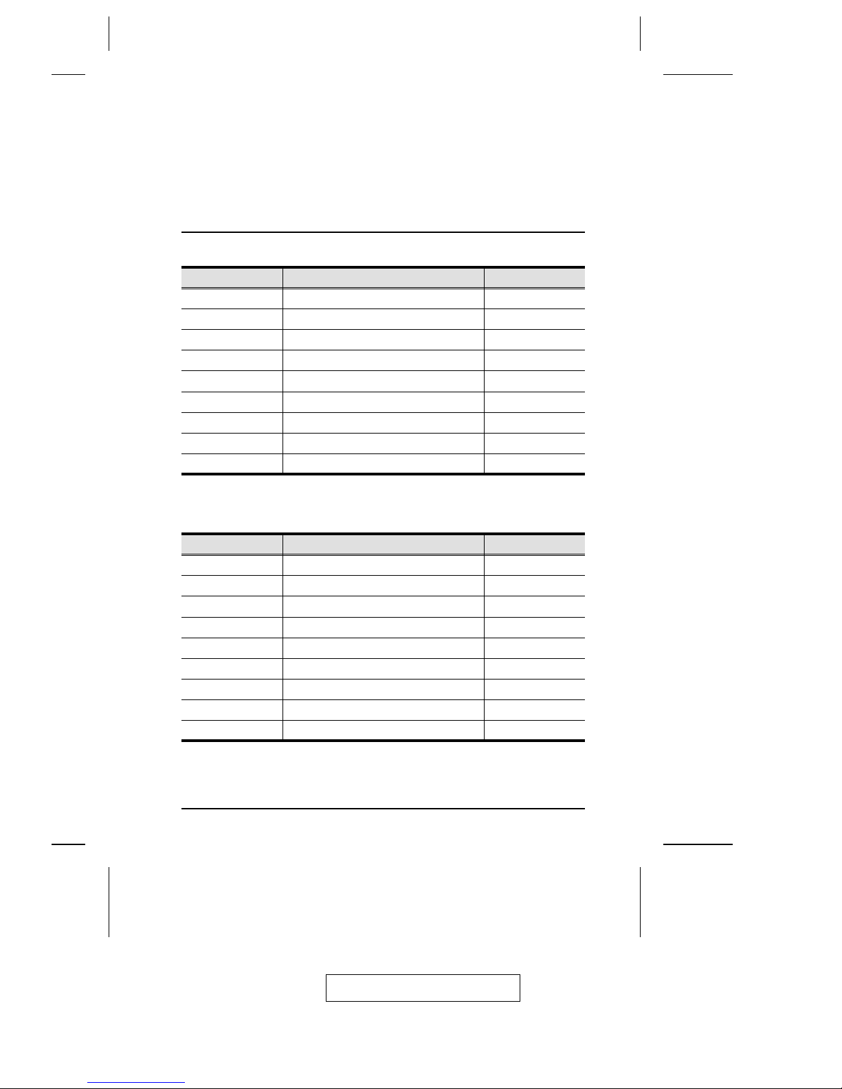
Appendix
Computer Connection Tables
KVM Switches Type Computers
1 CS-228 1 - 8
2 CS-128A / CS-138A / CS-9138 8 - 15
3 CS-128A / CS-138A / CS-9138 15 - 22
4 CS-128A / CS-138A / CS-9138 22 - 29
5 CS-128A / CS-138A / CS-9138 29 - 36
6 CS-128A / CS-138A / CS-9138 36 - 43
7 CS-128A / CS-138A / CS-9138 43 - 50
8 CS-128A / CS-138A / CS-9138 50 - 57
9 CS-128A / CS-138A / CS-9138 57 - 64
KVM Switches Type Computers
1 CS-228 1 - 8
2 CS-124A 8 - 11
3 CS-124A 11- 14
4 CS-124A 14 - 17
5 CS-124A 17 - 20
6 CS-124A 20 - 23
7 CS-124A 23 - 26
8 CS-124A 26 - 29
9 CS-124A 29 - 32
2005-11-29
27
Page 38

Specifications
Function Specification
Computer
Connections
Direct 8
Max 64 (via Cascade)
Port Selection OSD (On Screen Display)
LEDs Power 1 (Blue)
On Line Port 8 (Orange)
Selected Port 8 (Green)
Console
Connectors
Keyboard 2 x 6 pin mini-DIN female
Mouse 2 x 6 pin mini-DIN female
Video 2 x HDB-15 female
Audio 2 x 3.5mm Mini Stereo Jacks (Microphone)
2 x 3.5mm Mini Stereo Jacks (Speakers)
Computer Port Connectors 8 x 25 pin D Type female
On Screen Display (OSD) PC Names; ID Numbers; Port Status
Scan Interval (OSD Select) User Specified: 1 - 255 secs.
Emulation Keyboard PS/2 and PC/AT
Mouse PS/2 and Serial
Video 1920 x 1440; DDC2
Power Consumption DC 9V 7.2W (max.)
Operating Temperature 5 - 40
o
C
Storage Temperature -20 - 60
o
C
Humidity 0 - 80% RH, Non-condensing
Housing Metal
Weight 2.7 kg
Dimensions (L x W x H) 45 x 17 x 6.7 cm (19" 1U)
2005-11-29
CS-228 User Manual
28
Page 39
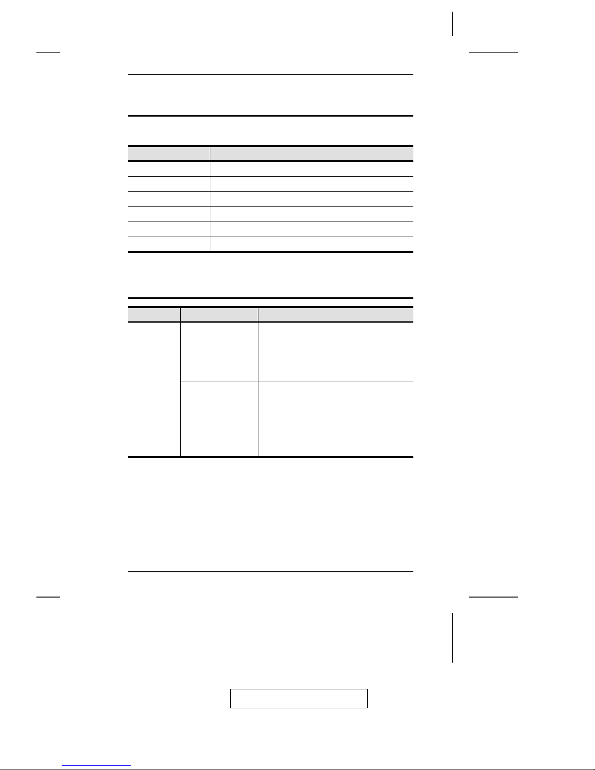
OSD Factory Default Settings
The factory default settings are as follows:
Setting Default
MULTI-USER MODE Enabled
ACCESS TIMEOUT 2 Seconds
OSD HOTKEY [Ctrl] [Ctrl]
DISPLAY MODE The Port Number plus the Port Name
DISPLAY DURATION 3 Seconds
SCAN DURATION 3 Seconds
Troubleshooting
Symptom Possible Cause Action
Keyboard
and/or
Mouse not
responding.
The connection from
the selected port to
the target computer
has been broken, or
the computer is
turned OFF.
Check the Online LED for the selected port.
If it is not lit:
1. Check to see that the computer is
powered ON.
2. Check the cables to make sure they are all
properly connected.
Keyboard/Mouse
need to be reset.
1. Unplug the keyboard and/or Mouse
connector from the Console Keyboard
and/or Mouse Ports, then plug it/them back
in.
2. Use a thin object (such as the end of a
paper clip, or a ballpoint pen), to depress the
K/M Reset Switch (located on the front
panel).
2005-11-29
Appendix
29
Page 40

Limited Warranty
IN NO EVENT SHALL THE DIRECT VENDOR’S LIABILITY EXCEED
THE PRICE PAID FOR THE PRODUCT FROM THE DIRECT,
INDIRECT, SPECIAL, INCIDENTAL OR CONSEQUENTIAL
DAMAGES RESULTING FROM THE USE OF THE PRODUCT, DISK
OR ITS DOCUMENTATION.
The direct vendor makes no warranty or representation, expressed, implied,
or statutory with respect to the contents or use of this documentation, and
specially disclaims its quality, performance, merchantability, or fitness for
any particular purpose.
The direct vendor also reserves the right to revise or update the device or
documentation without obligation to notify any individual or entity of such
revisions, or update. For further inquires please contact your direct vendor.
2005-11-29
CS-228 User Manual
30
Page 41

B
Basic Operation . . . . . . . . . . . . . . 13
C
Cables . . . . . . . . . . . . . . . . . . . . . . . 4
F
FCC Information . . . . . . . . . . . . . . ii
Features. . . . . . . . . . . . . . . . . . . . . . 2
Front View . . . . . . . . . . . . . . . . . . . 5
H
Hardware Requirements
Cables. . . . . . . . . . . . . . . . . . . . . 4
Computer . . . . . . . . . . . . . . . . . . 3
Consoles. . . . . . . . . . . . . . . . . . . 3
Hardware Setup . . . . . . . . . . . . . . . 7
I
Installation
Single Stage . . . . . . . . . . . . . . . . 9
Two Stage . . . . . . . . . . . . . . . . 11
O
OSD
Factory Default Settings . . . . . 29
Functions . . . . . . . . . . . . . . . . . 18
Main Menu Headings . . . . . . . 16
Navigation . . . . . . . . . . . . . . . . 17
Overview . . . . . . . . . . . . . . . . . 15
Port Numbering . . . . . . . . . . . . 16
Overview . . . . . . . . . . . . . . . . . . . . 1
R
Rack Mounting. . . . . . . . . . . . . . . . 8
Safety information . . . . . . . . . . vi
Rear View. . . . . . . . . . . . . . . . . . . . 6
S
Safety Instructions
General. . . . . . . . . . . . . . . . . . . iv
Rack Mounting . . . . . . . . . . . . vi
Stacking . . . . . . . . . . . . . . . . . . . . 7
Index
2005-11-29
31
 Loading...