

Page 1
OVERVIEW 1
FEATURES 2
HARDWARE REQUIREMENTS 3
CONSOLE 3
PC 3
CABLES 3
UNPACKING 4
FRONT VIEW 4
REAR VIEW 5
INSTALLATION 6
SINGLE STAGE INSTALLATION 6
TWO STAGE INSTALLATION 6
THREE STAGE INSTALLATION 8
OPERATION 10
MANUAL PORT SELECTION 10
HOT KEY PORT SELECTION 10
SELECTING THE ACTIVE PORT 11
QUICK VIEW SCAN MODE 11
OSD SELECTION 12
THE MAIN MENU HEADINGS 13
THE FUNCTION KEYS 13
TABLE OF CONTENTS
Page 2
APPENDIX 17
SELECTED LED DISPLAY 17
DIP SWITCH SETTINGS 17
TROUBLESHOOTING 18
SPECIFICATIONS 19
MASTER VIEW - PC CONNECTION TABLE 20
RADIO & TV INTERFERENCE STATEMENT 20
LIMITED WARRANTY 20
TABLE OF CONTENTS
Page 3

PACKING LIST
The complete Master View CS-138D package consists of:
One Master View CS-138D CPU Switch
One DC Power Adapter
One User Manual
• Check to make sure that the unit was not damaged in shipping. If you
encounter a problem, contact your dealer.
• Please read this manual thoroughly and follow the installation procedures
to prevent any damage to the CS-138 and/or the connecting devices.
©Copyright 1998 ATEN®International Co., Ltd.
Manual Part No. PAPE-0115-100
Printed in Taiwan 10/1998
All brand names and trademarks are the registered property of their respective owners .
Page 4

The Master View CS-138D CPU Switch is a control unit that allows access to multiple
PCs from a single console (keyboard, mouse, and monitor). Before the
development of the Master View, the only way to control multiple computer
configurations from a single console was through a complex and costly network
system. Now, with the Master View CS-138D, you can easily access multiple
computers in a cost effective manner.
The Master View CS-138D provides three convenient methods to access any PC
connected to the system: using the port selection switches located on the Master
View CS-138D’s front panel; entering a Hot Key combination from the keyboard;
and using the menu driven OSD (On Screen Display) feature.
Setup is fast and easy; plugging cables into their appropriate ports is all that is
entailed. There is no software to configure, so there is no need to get involved in
complex software installation routines or be concerned with incompatibility
problems. Since the Master View CS-138D intercepts keyboard input directly, it works
on any hardware platform and with all operating systems.
A Master View CS-138D unit can control up to eight PCs. Units can be cascaded to
three levels, which means that up to 43 Master Views can control up to 302 PCs all from a single keyboard-monitor-mouse console. A powerful Quick View Scan
Mode feature allows you to auto scan and monitor the activities of all operating
PCs on the installation one by one. To stop at a particular PC, simply press the
spacebar.
There is no better way to save time and money than with a Master View CS-138D
installation. By allowing a single console to manage all the attached PCs, the
Master View CS-138D eliminates the expense of purchasing a separate keyboard,
monitor, and mouse for each PC as well as saving all the space they would take
up. It also eliminates the inconvenience and wasted effort involved in constantly
moving around from one PC to another.
User's Manual 1
OVERVIEW
Page 5

FEATURES
User's Manual 2
• Cascadable To Three Levels - Control Up to 302 PCs From a Single Console
• No Software Required - PC Selection via Front Panel Switches, Hot Keys, or OSD
(On Screen Display)
• Quick View Scan Mode for Monitoring Selected PCs
• PS/2 and Serial Mouse Emulation Provided For System Bootup
• Mouse Translation - Translates PS/2 Mouse Protocol to MS Mouse. Console’s PS/2
Mouse Controls All Connected PCs - Even Those With Serial Mice
• Microsoft Intellimouse, Logitech First Mouse+, Mouse Man+
....
Support
• SVGA, VGA and Multisync Monitor Support
• DDC (Display Data Channel) Support
• LED Display For Easy Status Monitoring
• Hot Pluggable: Add new PCs or Remove Connected PCs for Maintenance
without Powering down the MASTER VIEW CPU Switch CS-138D
• Supports Both Standard and High Quality CS Series Custom Connector Cables
• Rack Mountable in 19” System Rack
• Any Hard ware Plat Form-All Operating System
Page 6
HARDWARE REQUIREMENTS
User's Manual 3
Console
• One VGA, SVGA, or Multisync monitor capable of the highest resolution that you
will be using on any PC in the installation
• One PS/2 Mouse
• One PS/2 Style Keyboard
PC
The following equipment must be installed on each PC that is to be connected to
the system:
• A VGA, SVGA or Multisync card.
• Mouse port: Either a 6-pin mini-DIN (PS/2 style), or DB-9 (standard serial).
• Keyboard port: Either a 6-pin mini-DIN (PS/2 Style) with +5V DC on pin 4 and
Ground on pin 3, or a 5-pin DIN (AT Style) with +5V DC on pin 5 and ground on
pin 4.*
* See the note under Cables in the next section.
Cables
Although you can use standard cables to connect the PCs to the Master View CS138D, for optimum signal integrity and to simplify the layout, we strongly
recommend that you use the high quality CS Custom Cable sets described in the
table below:
Note: The Master View only uses PS/2 style connectors for its keyboard ports. If the
PC you want to connect uses AT style connectors, you will need an AT-to-PS/2
adapter in order to plug the AT style keyboard connector cable into the
Master View keyboard port.
PC Connector Style
AT (5 pin DIN)
PS/2 (6 pin mini-DIN)
AT & PS/2
ATEN Part Number
2L-1001A (1.8 m) or 2L-1003A (3 m)
2L-1001P/S (1.8 m) or 2L-1003P/S (3 m)
2L-1001U (1.8 m) or 2L-1003U (3 m)
Page 7
UNPACKING
User's Manual 4
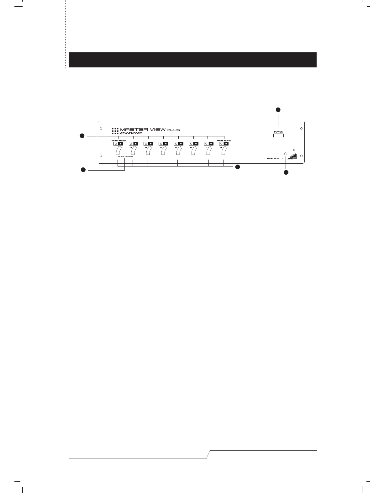
Front View:
1. Status LEDs:
On Line: Lights RED to indicate that the PC attached to the corresponding port
is up and running.
Selected: Lights GREEN to indicate the currently selected port. Depending on the
port’s status, the LED may flash according to a specific pattern (see
the table in the Appendix for details).
2. Port Selection Switches
Press a switch to access the PC attached to the corresponding port.
3. K/M Reset
If the keyboard and mouse get stuck and need to be reset, simultaneously press
this two switch combination.
4. Power Switch
5. Power LED
Lights to indicate that the Master View CS-138D has been turned On and is
receiving power.
1
2
5
4
3
Page 8
User's Manual 5
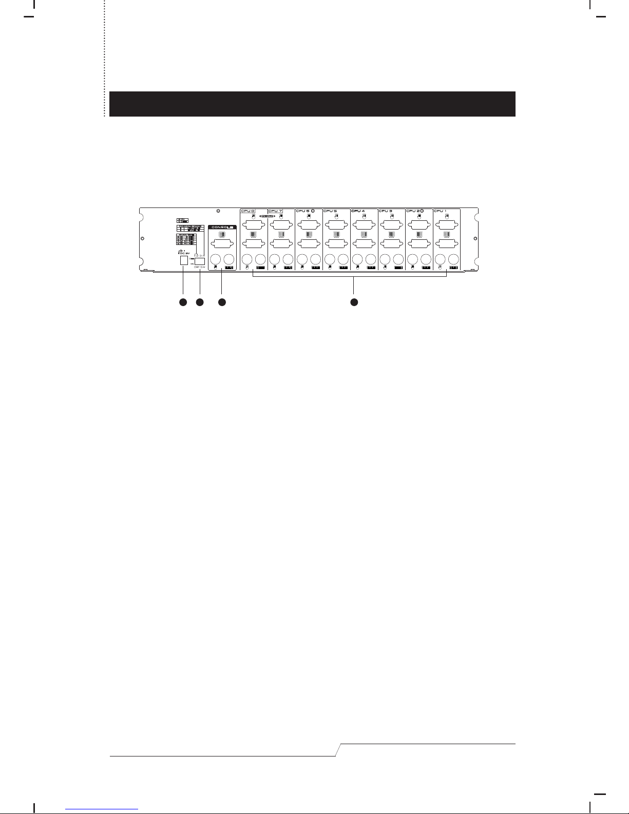
Rear View:
1. Power Jack
The DC power adapter plugs in here.
2. DIP Switch
A four segment DIP Switch. Switches 1 and 2 select the Scan Time; Switch 3 has
no assignment at this time; Switch 4 selects the Cascade Mode. See the table in
the Appendix for details.
3. Console Port Section
Your monitor, keyboard and mouse plug in here.
4. CPU Port Section
The cables (as described in the Hardware Requirements section) from the PCs
monitor, keyboard and mouse ports plug in here.
1
2
3
4
Page 9
User's Manual 6
INSTALLATION
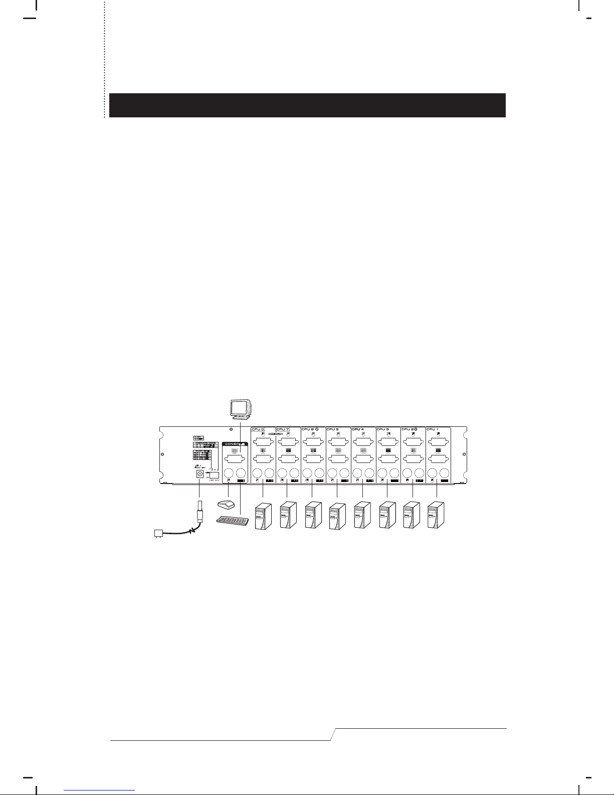
Single Stage Installation
1.Set the Master View CS -138D ’s DIP Switch 4 to the ON (Cascade Disabled)
position.
2.Plug the monitor, keyboard, and mouse into the Console port connectors
(located to the left of the CPU ports) of the Master View CS-138D unit. Each port is
labeled with an appropriate icon to indicate itself.
3.In a Single Stage System, PCs connect to all of the Master View CS-138D’s CPU
ports (CPU 1-CPU 8). Use connector cable sets (as described in the Hardware
Requirements section), to connect the monitor, keyboard and mouse ports of
the PC to any available Master View CS-138D CPU Port, as shown in the diagram
below.
4.Plug the DC power adapter into the Master View CS-138D’s Power Jack.
5.Turn on the power to the Master View CS-138D.
6.Turn on the power to the connected PCs.
Note: You must turn on the power to the Master View CS-138D before turning on
the power to the PCs.
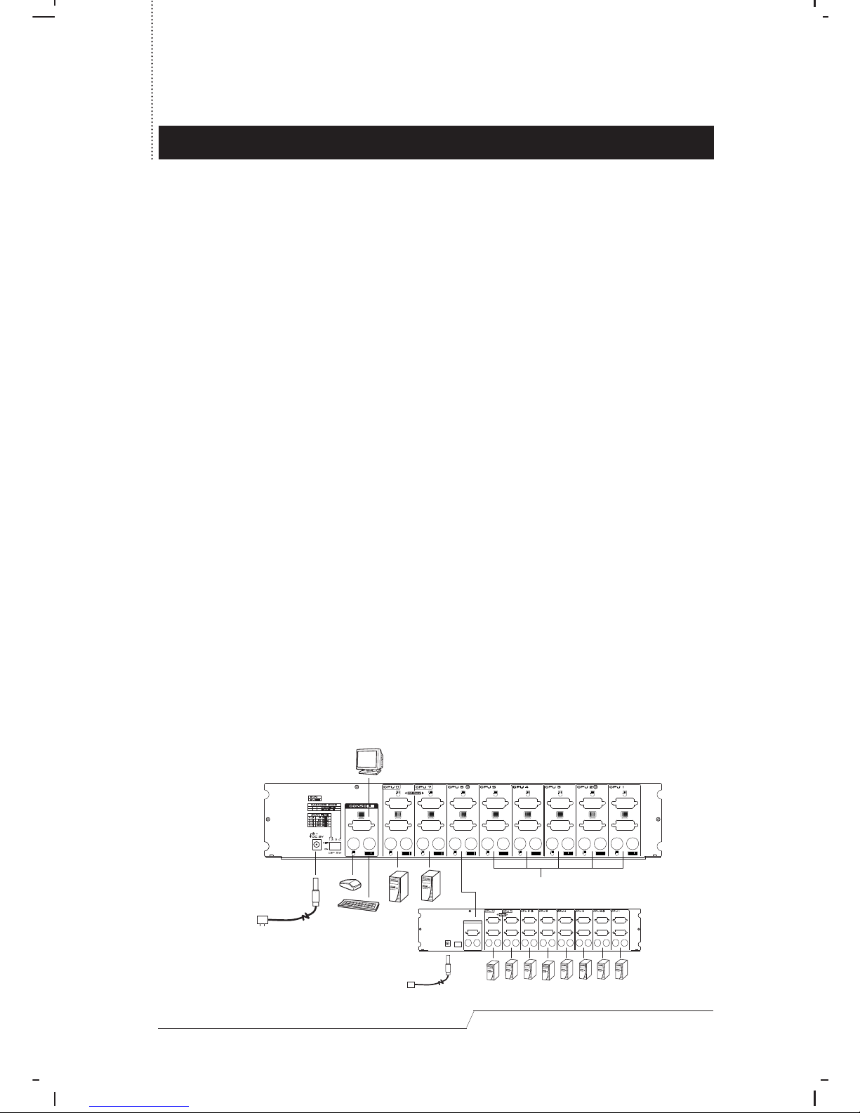
Two Stage Installation
To provide control for more than just eight PCs, up to six Master View CS-138D units
can be cascaded from the CPU ports of the parent unit. These units that connect
back to the original Master View CS-138D that the monitor, keyboard and mouse
are connected to (the First Stage unit), are considered Second Stage units. As
many as 50 PCs can be controlled in a complete two stage installation. A table
showing the relation between the number of PCs and the number of Master View
units needed to control them is provided in the Appendix. To set up a two stage
installation, do the following:
Page 10
User's Manual 7
1. Make sure that power to all the devices (Master View CS-138Ds and PCs) you will
be connecting up, as well as preexisting devices on the installation have been
turned off.
2. Make sure that DIP Switch 4 of the First Stage Master View CS-138D is set to the
ON (Cascade Disabled) position.
3. Make sure that DIP Switch 4 of the Second Stage Master View CS-138D is set to
the OFF (Cascade Enabled) position.
4. Use a PS/2 style connector cable set (as described in the Hardware Requirements
section), to connect from the Console Port connectors of the Second Stage
Master View CS-138D to any available CPU Port on the First Stage unit.
Note: When cascading, you can only connect back to CPU Ports 1-6 of the
parent unit. CPU Ports 7 and 8 are reserved for PC connections only.
5. Plug the DC power adapter into the Master View CS-138D’s Power Jack.
6. Repeat steps 2-5 for any other Second Stage Master View CS-138D units you
wish to connect.
7. Use connector cable sets (as described in the Hardware Requirements section),
to connect the monitor, keyboard and mouse ports of the PCs you want to
control to any available Master View CS-138D CPU Port, as shown in the diagram
below.
8. Turn on the power to all the Master View CS-138D units.
9. Turn on the power to all the connected PCs.
Note: You must turn the power to the Master View CS-138D units On before
turning on the power to the PCs.
To PC or Second stage
1st
Stage
2st
Stage
Page 11

User's Manual 8
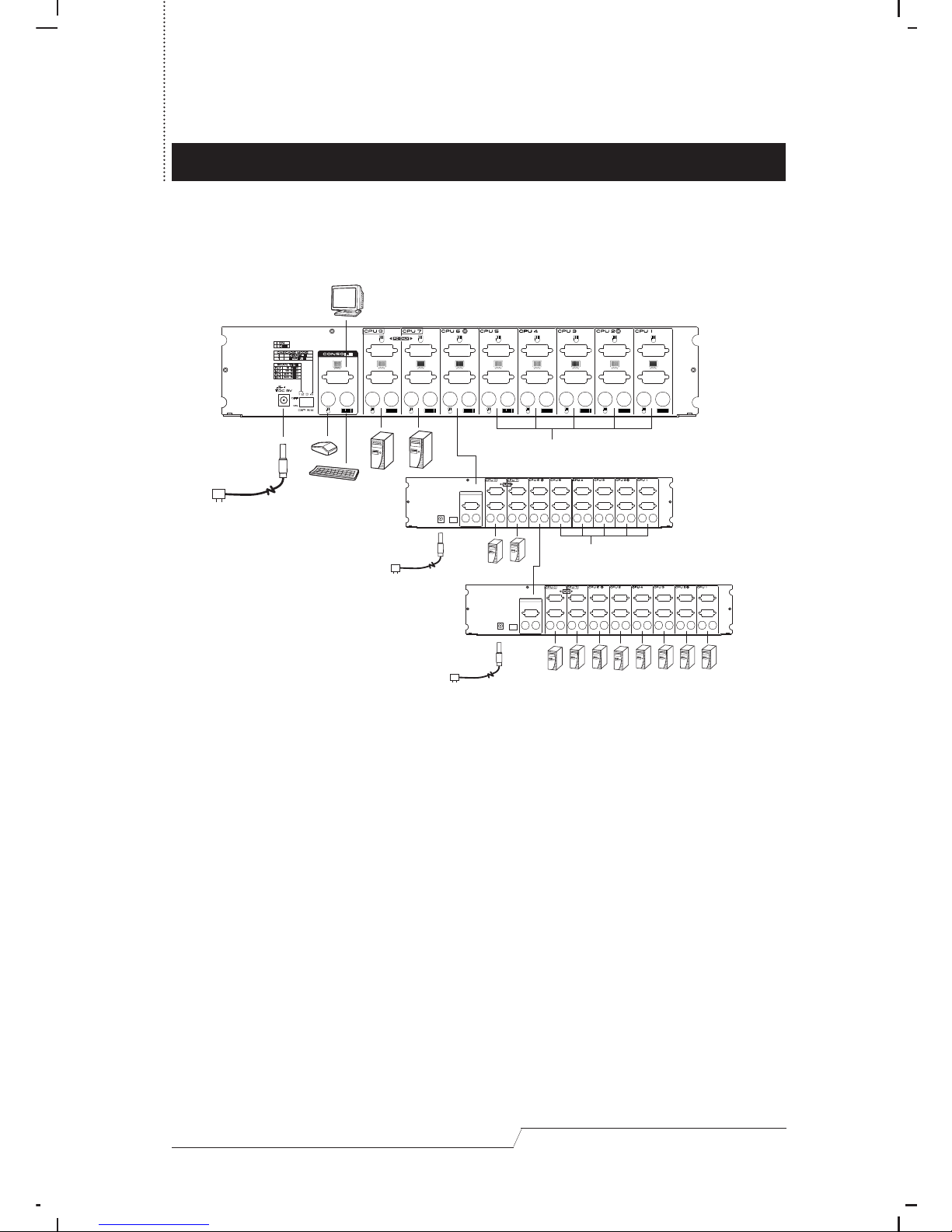
Three Stage Installation
The procedures for setting up a three stage Master View CS-138D configuration are
essentially the same as for a two stage installation. With a three stage setup,
however, as many as 302 PCs can be controlled in a complete installation. A table
showing the relation between the number of PCs and the number of Master View
units needed to control them is provided in the Appendix.
Note: Master View CS-138D units can not be cascaded beyond the third level.
To set up a three stage installation, do the following:
1. Make sure that power to all the Master View CS-138D units, as well as the power
to all the PCs that you are connecting up has been turned off.
2. Make sure that DIP Switch 4 of the First Stage Master View CS-138D is set to the
ON (Cascade Disabled) position.
3. Make sure that DIP Switch 4 of all Second Stage Master View CS-138D units are
set to the OFF (Cascade Enabled) position.
4. Make sure that DIP Switch 4 of the Third Stage Master View CS-138D unit is set to
the OFF (Cascade Enabled) position.
5. Use a PS/2 style connector cable set (as described in the Hardware
Requirements section), to connect from the Console Port connectors of the Third
Stage Master View CS-138D to any available CPU Port on the Second Stage
Master View CS-138D unit.
Note: When cascading, you can only connect back to CPU Ports 1 - 6 of the
parent unit. CPU Ports 7 and 8 are reserved for PC connections only.
6. Plug the DC power adapter into the Master View CS-138D’s Power Jack.
7. Repeat steps 2 - 6 for any other Third Stage Master View CS-138D units you wish
to connect.
8. Use connector cable sets (as described in the Hardware Requirements section),
to connect the monitor, keyboard and mouse ports of the PCs you want to
control to any available Master View CS -138D CPU Port, as shown in the
diagram below.
9. Turn on the power to all the Master View CS-138D units.
10.Turn on the power to all the connected PCs.
Page 12
User's Manual 9
Note: You must turn the power to the Master View CS-138D units On before turning
on the power to the PCs.
To PC or Second stage
To PC or Third stage
Page 13

OPERATION
User's Manual 10
Controlling all the PCs connected up in your Master View CS-138D installation from
a single console could not be easier. Three methods are available that provide
instant access to any PC on the chain:
• Manual - simply press the appropriate port selection switch on the Master View
CS-138D’s front panel;
• Hot Key - enter combinations from the keyboard;
• OSD - use the On Screen Display menus.
Manual Port Selection
Manual selection simply involves pressing the Port Selection switch on the front
panel of the Master View CS-138D unit that corresponds to the PC that you want to
access. After you press the switch, the Selected LED lights to indicate that the port
is currently selected. To access a PC connected to a Second or Third Stage Master
View CS-138D unit, you must press the appropriate Port Selection switch on the
Master View unit that connects directly to the PC you want to access.
Hot Key Port Selection
Hot Key navigation allows you to access connected PCs directly from the
keyboard, instead of having to manually select them by pressing Port Selection
switches. The Master View CS-138D provides two Hot Key navigation features:
• Selecting the Active Port;
• Quick View Scan Mode.
All Hot Key operations begin by pressing and releasing the Alt+Ctrl+Shift
combination to signal the Master View CS-138D that a Hot Key command is
coming; the remaining keys are pressed and released individually.
Note: The Alt+Ctrl+Shift combination must all be on the same side (i.e.,
LeftAlt+LeftCtrl+LeftShift or RightAlt+RightCtrl+RightShift).
Hot Key port selection is disabled while the OSD feature (see the OSD Port
Selection section) is active. When OSD is active, it is expected that you will
use the on screen menu procedure to select ports. In order to use the Hot
Key method, you must first exit OSD (by pressing [Esc] until the OSD menu is
gone from the screen).
Page 14

User's Manual 11
Selecting the Active Port:
Since each CPU port is assigned a unique numeric ID, you can directly access any
PC on any level of the installation using a Hot Key combination that specifies the
Port ID of the CPU Port that the PC is connected to. The steps involved are:
1. Press and release Alt+Ctrl+Shift.
2. Key in the appropriate Port ID one digit at a time (see below for details).
3. Press [Enter] to complete your selection. The Master View CS-138D beeps once
to acknowledge the change of active ports.
The Port ID is a one, two, or three digit number that is determined by the CPU Port
and Stage Level of the Master View unit that the PC is connected to. The first digit
represents the CPU Port of the First Stage Master View CS-138D; the second digit
represents the CPU Port of the Second Stage; the third digit represents the CPU Port
of the Third Stage.
Examples:
• To access a PC attached to a First Stage unit, simply key in the number of the
CPU Port (1-8) that the PC is attached to for the Port ID (step 2, above).
• To access a PC attached to a Second Stage unit, key in a two digit number for
the Port ID (press and release each number separately). The first digit represents
the port number on the First Stage unit that the Second Stage unit connects
back to; the second digit represents the port number on the Second Stage unit
that the PC is connected to. For example, a Port ID of 2 3 refers to a PC that is
connected to CPU Port 3 of a Second Stage unit that
, in turn, connects back to
CPU Port 2 of the First Stage unit.
• To access a PC attached to a Third Stage unit, key in a three digit number
following the method described for the Second Stage unit. For example, a Port ID
of 2 4 1 refers to a PC that is connected to CPU Port 1 of a Third Stage unit that
connects back to CPU Port 4 of a Second Stage unit which, in turn, connects
back to CPU Port 2 of the First Stage unit.
Quick View Scan Mode:
The Master View CS-138D has a powerful Quick View Scan Mode feature that
allows you to scan through each of the active CPU Ports of all the Master View units
in the installation. The amount of time it dwells on each port is determined with
segments 1 and 2 of the DIP Switch located at the left of the Master View
CS-138D’s rear panel (see the table in the Appendix for setting details), or with an
Page 15
User's Manual 12
OSD selection (see the OSD Port Selection section for details). To invoke Quick
View Scan Mode, key in the following Hot Key combination:
Alt+Ctrl+Shift + 0 [Enter]
While Quick View Scan Mode is in effect, the Selected LED of the currently active
port flashes On and Off equally to indicate that it is being accessed in Quick View
Scan Mode. Scanning continues until the operator presses the Spacebar to stop
scanning and exit Quick View Scan Mode. The port that was currently active at the
time scanning stopped, is the one that displays on the monitor.
Note: While Quick View Scan Mode is in effect, none of the other keyboard keys
will function. You must exit Quick View Scan Mode by pressing [Spacebar]
in order to use the console for anything else.
If the scanning stops on an empty port (no device is attached to that port),
the monitor screen will be blank, and the mouse and keyboard will have no
effect. To recover, key in the Hot Key sequence (see Hot Key Port Selection,
above), for any Port ID that has a PC attached.
OSD Port Selection
OSD (On Screen Display), provides a menu driven interface to handle the PC
switching procedure. Although Hot Key switching still works, using the OSD module is
a great deal more convenient - especially in large, cascaded installations where a
great number of PCs are connected to a several Master View CS-138D units, and it
is difficult to keep track of which port a particular PC is attached to.
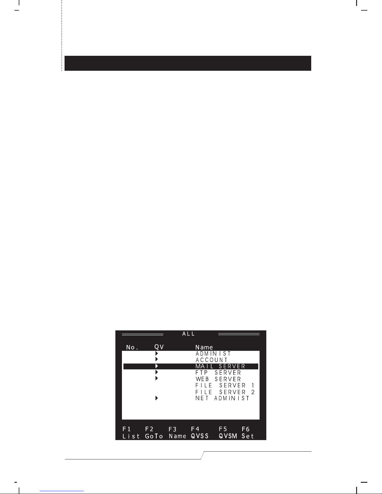
All operations start from the OSD Main Menu. To pop up the menu, press [Ctrl] twice:
1-1-1
2-1-1
4-1-1
5-1-1
6-1-1
7-X-X
8-X-X
3-1-1
Page 16
User's Manual 13
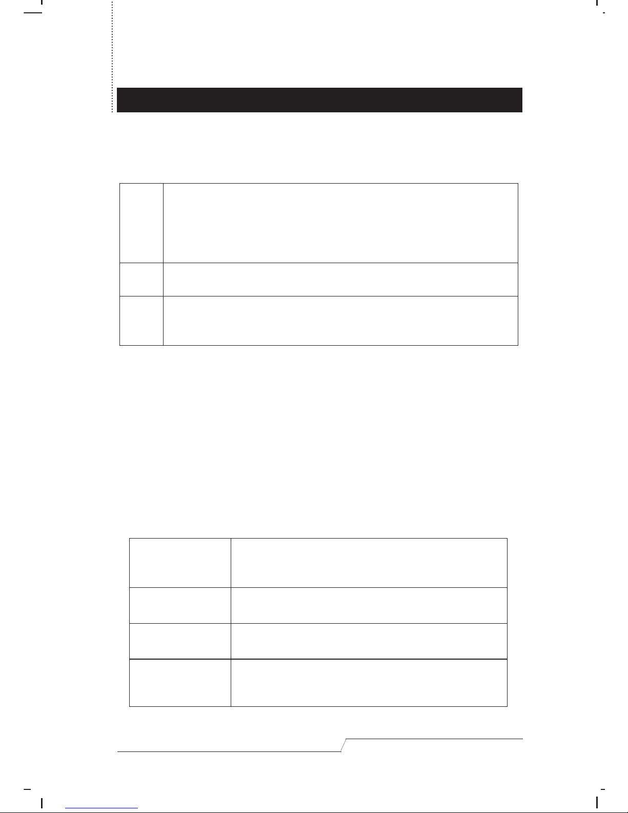
To dismiss the menu, press [Esc]. Use of the OSD Main Menu is explained below:
The OSD Main Menu Headings:
The Function Keys:
Pressing a Function Key brings up a related submenu that is used to configure and
control the OSD to make it convenient for you to work with. For example, you can:
limit the list you wish to view; rapidly switch to any port; create or edit a port name;
designate a port to be included in the Quick View Scan Mode group; scan
selected ports only; or make OSD setting adjustments.
• F1 List:
This function lets you select which ports you wish to see. Pressing [F1] cycles
through the following choices:
No.
QV
Name
Lists the port numbers that can be switched to. The simplest method to
access a particular PC (assuming you know which port it is attached to),
is to use the Up and Down Arrow Keys to move the Highlight Bar to the
desired location, then press [Enter] twice. An explanation of port
numbering is given in the section on the GoTo (F2) Function key.
Ports that have been selected for Quick View Scan Mode (see F4 and F5,
p.14+15), have an arrowhead displayed in this column to indicate so.
For convenience in remembering which PC is attached to a particular
port, the port can be named (see F3, p.14). If a port has been named,
its name appears in this column.
All
QVSM List
Name List
QVSM+Name List
Lists the port numbers and names (if they have been
specified - see F3 p.14) of all the ports that the CPU
Switch can access.
Lists only the ports that have been selected for scanning
under Quick View Scan Mode (see F5, p.15 ).
Lists only the ports that have been assigned names
(see F3, p.14 ).
Lists only the ports that have been assigned names (see
F3, p.13 ), and have been selected for scanning under
Quick View Scan Mode (see F4, p.14 ).
Page 17

User's Manual 14
Note: You can access any port on any list by using the Up and Down Arrow
keys to move the Highlight Bar to it, then press [Enter].
If you select a port that does not have a PC attached to it, or if the
attached PC is powered Off, the CS-138D will still switch to it, and will not
show an error.
• F2 GoTo:
GoTo allows you to switch directly to a port by keying in either its name or
number. Pressing [F1] while in this submenu toggles between the two
methods.
1. Key in the port name or port number, then press [Enter] to switch to the PC
that is attached to that port.
2. To return to the OSD Main Menu without making a choice, press [Esc].
Note: Ports are numbered according to which stage and which port number
they connect to (see Hot Key Port Selection, above).
• F3 Name:
This function allows you to name the currently highlighted CPU port (if it doesn’t
already have a name), or to modify/delete the port name if it does. To edit a
port name:
1. Use the Up and Down Arrow Keys to move the highlight bar to the port you want
(you can use the F1 List function to broaden or narrow the port selection list).
2. Press [F3].
3. Key in the new port name, or modify/delete the old one.
4. When you have finished editing, press [Enter] to have the change take
effect. To abort the change, press [Esc].
• F4 QVSS:
You can limit the number of ports that get automatically scanned by selecting
only the ones you want with the QVSS (Quick View Scan Select) function. [F4] is a
toggle that selects or deselects the currently highlighted port for the QVSM
(Quick View Scan Mode) function (see F5, 15). To select/deselect a port for
QVSM:
Page 18
User's Manual 15
1. Use the Up and Down Arrow Keys to move the highlight bar to the port.
2. Press [F4].
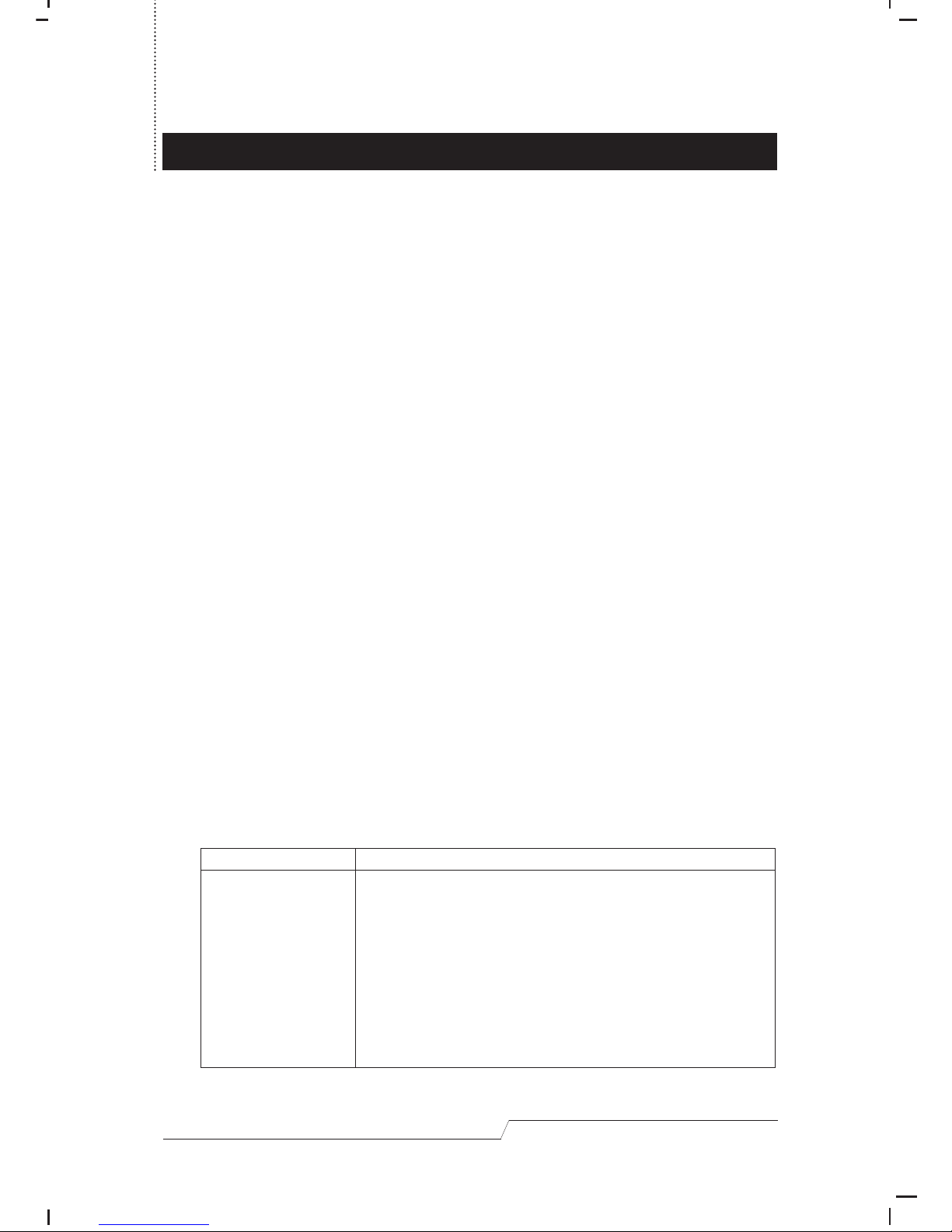
When a port has been selected for Quick View Scanning, an arrowhead
displays in the QV column to indicate so. When a port is deselected, the
arrowhead disappears.
• F5 QVSM:
Pressing [F5] initiates the Quick View Scan Mode, in which the OSD cycles
through all the ports that have been selected for Quick View Scanning (see
F4, p.14), and displays each one for the amount of time set with the Set Scan
Timeout function (see F6, below). When you want to stop at a particular
location, press [Spacebar] to stop scanning.
Note: If the scanning stops on an empty port (no device is attached to that
port), the monitor screen will be blank, and the mouse and keyboard will
have no effect. To recover, key in the Hot Key sequence for any Port ID
that has a PC attached (see Hot Key Port Selection, p.9).
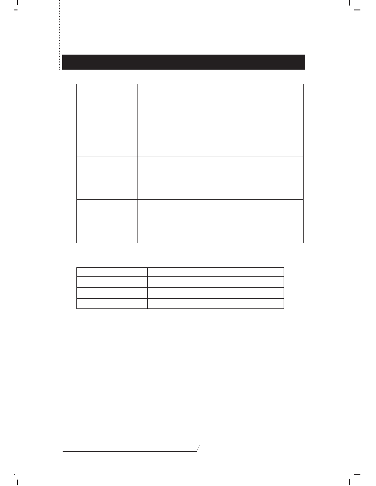
• F6 Set
When you press [F6] a submenu appears that allows you to configure the OSD
settings. To change a setting, use the Up and Down Arrow Keys to move the
highlight bar to it, then press [Enter] to cycle through the choices. When you
have finished making your selections, press [Esc] to return to the OSD Main
Menu. The settings are explained in the table below:
Setting
Show Port ID:
Function
Determines how long a Port ID is displayed for. There are
two choices: On Change - which displays the Port ID for 3
seconds after a port change has taken place; and Always -
which displays the Port ID at all times.
If Always is selected and you want to remove the Port ID
from the display, you can disable the OSD function with the
following Hot Key combination: Alt+Ctrl+Shift + F10. To
reenable the OSD function, key in the following Hot Key
combination: Alt+Ctrl+Shift + F9.
Page 19
User's Manual 16
The factory default settings are as follows:
Setting
Display Mode:
Set Scan Timeout:
Set Channel Position:
Clear All Settings:
Function
Selects how the Port ID is displayed: either the Port Number
alone, or the Port Number plus the Port Name (provided a
name has been assigned).
Determines how long the OSD dwells on each port when it
cycles through the selected ports in Quick View Scan Mode.
The available options are: 3, 5, 10, 15, 20, 30, 40, and 60
seconds. This selection overrides the DIP Switch setting.
Allows you to position where the Port ID appears on the
screen. After you highlight this item and press [Enter], the
menu disappears and the Port ID is displayed. Use the Arrow
Keys to position the Port ID display, then press [Enter] to lock
the position and return to the Set submenu.
Clears all settings from memory, and returns the unit to the
factory defaults. While the settings are being cleared, a
message appears on the display to indicate so. After the
settings have been cleared, another message appears to
indicate that the procedure completed successfully.
Setting
Show Port ID:
Display Mode:
Set Scan Timeout:
Default
On Change
The Port Number plus the Port Name
5 Seconds
Page 20
APPENDIX
User's Manual 17
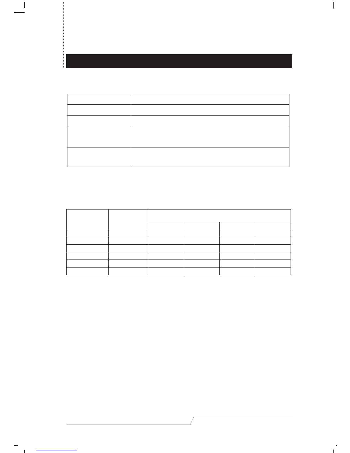
SELECTED LED Display:
DIP Switch Settings
Note: Switch 3 has no assignment at this time. It doesn’t matter what it is set to.
Activity
Off
On (Steady)
Flashing
(On short; Off long)
Flashing
(On and Off equal)
Meaning
Port is not selected.
Port is connected to an active PC.
Port is connected to a lower stage Master View
CS-138D.
Port is connected to an active PC and is being accessed
in Quick View Scan Mode
Scan Time
(secs)
3
10
20
40
Cascade
Mode
Disabled
Enabled
1
On
Off
On
Off
X
X
2
On
On
Off
Off
X
X
3
X
X
X
X
X
X
4
X
X
X
X
On
Off
Switch
Page 21
User's Manual 18
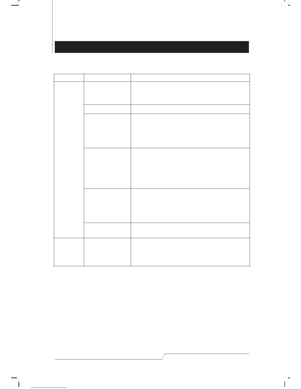
Troubleshooting
Symptom
Pressing the
Hot Keys gets
no response.
Mouse is not
responding.
Possible Cause
DIP Switch 4 settings
are incorrect.
OSD is enabled.
The connection from
the selected port to
the target PC has
been broken, or the
PC is turned OFF.
Improper keyboard
reset.
Improper CS-138D
reset.
Incorrectly keying in the
Hot Key combination.
Action
Make sure that Switch 4 of the First Stage unit is set to
ON; make sure that Switch 4 of all Second and Third
Stage units are set to OFF
Press Alt+Ctrl+Shift + F10 to disable OSD.
Check the Online LED for the selected port. If it is not lit:
1.Manually press one of the Select switches to connect
to a PC that is powered ON.
2.Check the cables to make sure they are all properly
connected.
1. Reset the keyboard (and mouse) by simultaneously
pressing and holding Select switches 1 and 2 on the
First Stage unit for three seconds. This can be done
as often as necessary.
2. Unplug the keyboard connector from the Console
Keyboard Port, then plug it back in.
Turn off all CS-138D units and wait five seconds before
turning them back on.
Note:If a PC uses a mouse protocol sensitive operating
system (such as NT), it may be necessary to
restart it after turning the CS-138D units back on.
After the Alt+Ctrl+Shift combination, make sure to press
and release the other keys one at a time.
Reset the mouse (and keyboard) by simultaneously
pressing and holding Select switches 1 and 2 on the First
Stage unit for three seconds. This can be done as often
as necessary.
Page 22
User's Manual 19
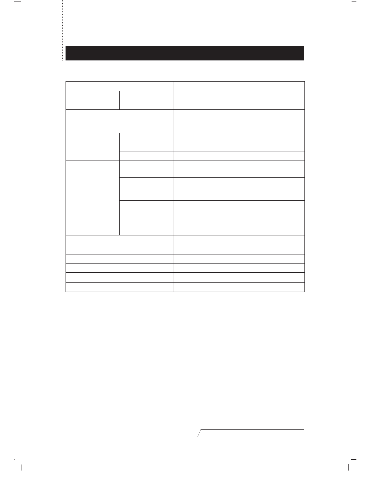
Specifications
Direct
(Daisy Chain)
Power
On Line
Selected
Keyboard
Mouse
Video
DIP Switch Select
OSD Select
Power Consumption
PC Connections
Port Selection
LEDs
Connectors
Scan Interval
Operating Temperature
Storage Temperature
Humidity
Enclosure
Weight
Dimensions (L x W x H)
DC 9V 460mA (max)
8
302 Max
Front Panel Switches
Hot Keys
On Screen Display
1
8
8
1 x 6 pin mini-DIN female (PS/2 style) - Console
8 x 6 pin mini-DIN female (PS/2 style) - CPU Ports
1 x 6 pin mini-DIN female (PS/2 style) - Console
8 x 6 pin mini-DIN female (PS/2 style) - CPU Ports
8 x DB-9 female (std. serial port) - CPU Ports
1 x HDB-15 female (std. VGA/SVGA) - Console
8 x HDB-15 male (std. VGA/SVGA) - CPU Ports
3, 10, 20, 40 secs.
3, 5, 10, 15, 20, 30, 40, 60 secs.
5 ~ 40˚ C
-20 ~ 60˚ C
0 ~ 80% RH, Noncondensing
Metal
3550 g
483 x 155 x 89 mm
Page 23
User's Manual 20
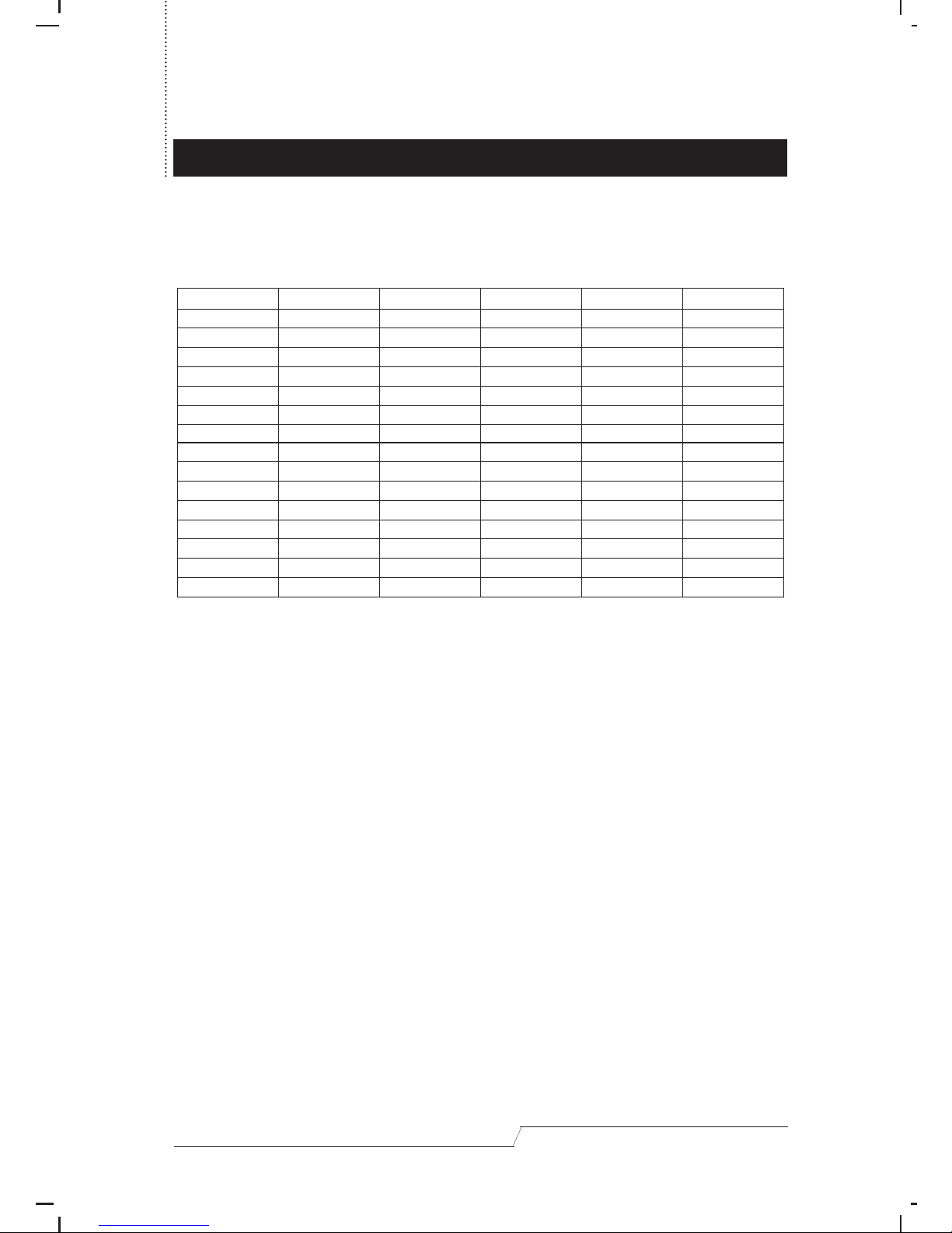
Master View - PC Connection Table
The following table indicates the relationship between the number of daisy chained
Master View Units and the number of PCs that they control:
Radio & TV Interference Statement
WARNING!!! This equipment generates, uses and can radiate radio frequency
energy and, if not installed andused in accordance with the instruction manual,
may cause interference to radio communications. This equipmenthas been tested
and found to comply with the limits for a Class A computing device pursuant to
Subpart J of Part15 of FCC Rules, which are designed to provide reasonable
protection against such interference when operated ina commercial environment.
Operation of this equipment in a residential area is likely to cause interference, in
which case the user at his own expense will be required to take whatever measures
may be required to correct the interference.
Limited Warranty
IN NO EVENT SHALL THE DIRECT VENDOR’S LIABILITY EXCEED THE PRICE PAID FOR THE
PRODUCT FROM THE DIRECT, INDIRECT, SPECIAL, INCIDENTAL OR CONSEQUENTIAL
DAMAGES RESULTING FROM THE USE OF THE PRODUCT, DISK, OR ITS DOCUMENTATION.
MV Units
16
17
18
19
20
21
22
23
24
25
26
27
28
29
30
PCs
107 - 113
114 - 120
121 - 127
128 - 134
135 - 141
142 - 148
149 - 155
156 - 162
163 - 169
170 - 176
177 - 183
184 - 190
191 - 197
198 - 204
205 - 211
MV Units
1
2
3
4
5
6
7
8
9
10
11
12
13
14
15
PCs
1 - 8
9 - 15
16 - 22
23 - 29
30 - 36
37 - 43
44 - 50
51 - 57
58 - 64
65 - 71
72 - 78
79 - 85
86 - 92
93 - 99
100 - 106
MV Units
31
32
33
34
35
36
37
38
39
40
41
42
43
PCs
212 - 218
219 - 225
226 - 232
233 - 239
240 - 246
247 - 253
254 - 260
261 - 267
268 - 274
275 - 281
282 - 288
289 - 295
296 - 302
Page 24

User's Manual 21
The direct vendor makes no warranty or representation, expressed, implied, or
statutory with respect to the contents or use of this documentation, and specially
disclaims its quality, performance, merchantability, or fitness for any particular
purpose.
The direct vendor also reserves the right to revise or update the device or
documentation without obligation to notify any individual or entity of such revisions,
or update. For further inquires please contact your direct vendor.
 Loading...