


REV. 12 (SW33)
MasterLan
INSTRUCTION MANUAL
pCO5/PGD1 DIGITAL CONTROLLER
HEAT PUMPS
MasterTherm
MASTERTHERM CZ s.r.o.
Václavské náměstí 819/43, 110 00 Praha 1
tel.:+ 420 311 516 567
e-mail: info@mastertherm.cz, www.mastertherm.cz

MasterLAN –INSTRUCTION MANUAL
TABLE OF CONTENTS:
1 Introduction ........................................................................................................................... 3
2 Terms definition ....................................................................................................................3
3 Hardware configuration.........................................................................................................3
3.1 pLAN address table ....................................................................................................... 4
3.2 Setting of the pCO pLAN address..................................................................................4
3.2.1 Protocol Set menu .................................................................................................. 5
3.3 Setting of the pDG pLAN address..................................................................................5
3.4 Setting communication between pCO and pGD ............................................................5
3.4.1 Single controller unit ............................................................................................... 6
3.4.2 Double controller unit..............................................................................................6
3.5 Setting summary............................................................................................................6
3.6 Wiring ............................................................................................................................7
3.6.1 MasterLAN wiring diagram .....................................................................................8
4 Software configuration .......................................................................................................... 9
4.1 Main Menu mask ...........................................................................................................9
4.2 Setting masks ................................................................................................................ 9
4.2.1 Master/Slave setting mask......................................................................................9
4.2.2 Master setting masks............................................................................................10
4.2.3 Source Control Masks ..........................................................................................13
4.2.4 OFFLINE configuration.........................................................................................14
4.2.5 Remote Functions ................................................................................................15
4.3 Control principle........................................................................................................... 16
4.3.1 Proportional control (recommended) ....................................................................16
4.3.2 PI control .............................................................................................................. 16
4.3.3 PID control............................................................................................................ 17
5 Alarms MasterLAN masks ..................................................................................................17
6 Additional notes ..................................................................................................................18
7 Revision history .................................................................................................................. 18
Revison 1.1, Ing. Jiří Jiránek 2

MasterLAN –INSTRUCTION MANUAL
1 Introduction
MasterLan is used for control of the multiple units installation. MasterLan requires specific
hardware and software configuration.
2 Terms definition
Explanation of some important terms and names used in the MasterLan description.
pCO5:
PLC controller used in the MasterTherm CZ heat pumps.
pGD1:
Semigraphical terminal used for communication with user. (pCO Graphic Display).
pLAN:
Carel based protocol dedicated for communication between pCO controllers and pGD displays.
(pCO Local Area Network). Principle of data transmision is based on RS485 standard.
pLAN address:
Address of each unit in the pLAN. Each pCO controller and pGD terminal has its own pLAN
address.
MasterLan:
MasterTherm heat pumps hardware and software solution used for multiple heat pumps
installation. Control is based on Master/Slave principle. One unit is configured like Master and
all other units are configured like Slaves. Maximum 16 compressor circuits could be controlled
in the MasterLan.
Single controller machine:
Heat pump with one refrigerant circuit and one pCO5 controller.
Double controller machine:
Heat pump with 2 compressor circuits, 2 controllers and 1 pGD terminal. Switching of the
display between 2 controllers is made by pressing PRG and ENTER keys simultaneously
3 Hardware configuration
Each compressor of the heat pump circuit is controlled by one pCO5 controller.
Single controller heat pump is also equipped with single pGD terminal. Double controller heat
pump is equipped with 2 pCO5 controllers and single pGD display, which is used for
communicating with both compressor circuits of the unit. Switching of the display between 2
controllers is made by pressing PRG and ENTER keys simultaneously. In the double heat
pump 2 controllers are already interconnected with pLAN protocol. Connection is made by 3
wires between terminals 61(Rx-/Tx-), 62(Rx+/Tx+) and 63(GND). Terminals are interconnected
with J11 pLAN connector of pCO5.
IMPORTANT: BEFORE ADDRESS SETTING IT IS ABSOLUTLY NECESSARY TO
DISCONNECT J11 pLAN CONNECTOR FROM ALL CONTROLLERS.
Revison 1.1, Ing. Jiří Jiránek 3

MasterLAN –INSTRUCTION MANUAL
3.1 pLAN address table
Single compressor units:
Unit type pCO controller
pLAN address
Master 1 32
Slave 1 2 31
Slave 2 3 30
Slave 3 4 29
Slave 4 5 28
Slave 5 6 27
Slave 6 7 26
Slave 7 8 25
This text type is default factory setting.
Double compressor units:
Unit type pCO controller
pLAN address
Master 1 32
Slave 1 2 -
Slave 2 3 31
Slave 3 4 Slave 4 5 30
Slave 5 6 Slave 6 7 29
Slave 7 8 -
This text type is default factory setting.
pGD terminal
pLAN address
pGD terminal
pLAN address
3.2 Setting of the pCO pLAN address
IMPORTANT: BEFORE ADDRESS SETTING IT IS ABSOLUTLY NECESSARY TO
DISCONNECT J11 pLAN CONNECTOR FROM ALL CONTROLLERS.
• Disconnect J11 connector from all pCO controllers
• Power ON the pCO controller
• Enter menu "Protocol Set"
• Set the address according to the table
• Repeat this procedure for all units controllers
Revison 1.1, Ing. Jiří Jiránek 4

MasterLAN –INSTRUCTION MANUAL
Display address
3.2.1 Protocol Set menu
List password mask and enter the OEM Expert password code. Enter menu and list "Protocol
Set", confirm ENTER and find following mask using UP key.
Jump with cursor to "pCO Address" and set address according to table above. Address is
changed immediately.
Use ESC to return to the menu.
3.3 Setting of the pDG pLAN address
Each pCO controller and pGD display address must be set according to the table above.
• Connect pGD display to the pCO controller
• Power ON pCO
• Press “UP”+“ENTER“+”DOWN” keys simultaneously until following display appears
Setting…………..: xx
I/O Board address:xx
• Use keys “UP”/”DOWN” to change address of the pGD according to the table above.
• Confirm selection pressing „ENTER“ key
3.4 Setting communication between pCO and pGD
This procedure requires correct setting of the pCO according to the pLAN address table.
Revison 1.1, Ing. Jiří Jiránek 5

MasterLAN –INSTRUCTION MANUAL
Display address
Terminal config
P:xx Adr Priv/Shared
3.4.1 Single controller unit
• Connect the pGD to the pCO controller
• Power ON the pCO, wait for pCO initialization, it takes cca 1 minute.
• Press “UP”+“ENTER“+”DOWN” keys simultaneously until following display appears
• Use keys “UP”/”DOWN” to change address of the pGD according to the pLAN address
table
• Confirm selection pressing „ENTER“ key
• Wait until I/O Board address appears beside “--” symbol
• Confirm pressing ENTER key, following screen will appear
• Pressing ENTER key, following screen will appear
• Set Trm1 address according to the unit You are setting, confirm ENTER
• Set type of terminal to “Pr”, confirm ENTER until You reach Yes/No array
• Change array to “Yes” and confirm ENTER
Setting…………..: xx
I/O Board address:xx
Press ENTER
to continue
Trm1 xx Pr
Trm2 xx -Trm3 xx -- Ok? Yes
3.4.2 Double controller unit
Do procedure as for single compressor circuit, but set type of terminal to Shared, “Sh”. You
have to do it for both controllers in the unit.
3.5 Setting summary
• Disconnect all J11 terminals from all controllers
• Set pCO address for all controllers
• Set pGD address for all pGDs
• Set commincation between pCO and pGD
• Switch all controllers OFF
• Return J11 connectors to the pCO controllers
Revison 1.1, Ing. Jiří Jiránek 6

MasterLAN –INSTRUCTION MANUAL
3.6 Wiring
For correct function make wiring connection using twisted pair shielded cable between 61, 62
and 63 terminals of all electric control boards.
NOTE: For correct pLAN function at least one pGD must be installed.
Please see following wiring diagram for proper installation.
Revison 1.1, Ing. Jiří Jiránek 7

MasterLAN –INSTRUCTION MANUAL
3.6.1 MasterLAN wiring diagram
Revison 1.1, Ing. Jiří Jiránek 8

MasterLAN –INSTRUCTION MANUAL
4 Software configuration
For the access to the MasterLAN configuration You have to enter the OEM password.
4.1 Main Menu mask
MasterLAN masks could be found in the main mask loop, using the UP and DOWN keys from
„ICON“ mask.
Master Slaves 1 to 7
Compressor
status 0 - OFF
1 - ON
Heater
status
Slaves 8 to 15
4.2 Setting masks
To enter MasterLAN setting displays please press PRG button on the main MasterLAN display.
4.2.1 Master/Slave setting mask
MasterLAN control Enabled/Disabled
Unit in the MasterLAN system Compressor steps Heater steps
Master/Slave1/Slave2/…/SlaveX
You can Enable or Disable MasterLAN control on this mask. No more masks are available if the
unit is Slave.
Press ESC key for return to the main mask loop.
Revison 1.1, Ing. Jiří Jiránek 9
MasterLAN –INSTRUCTION MANUAL
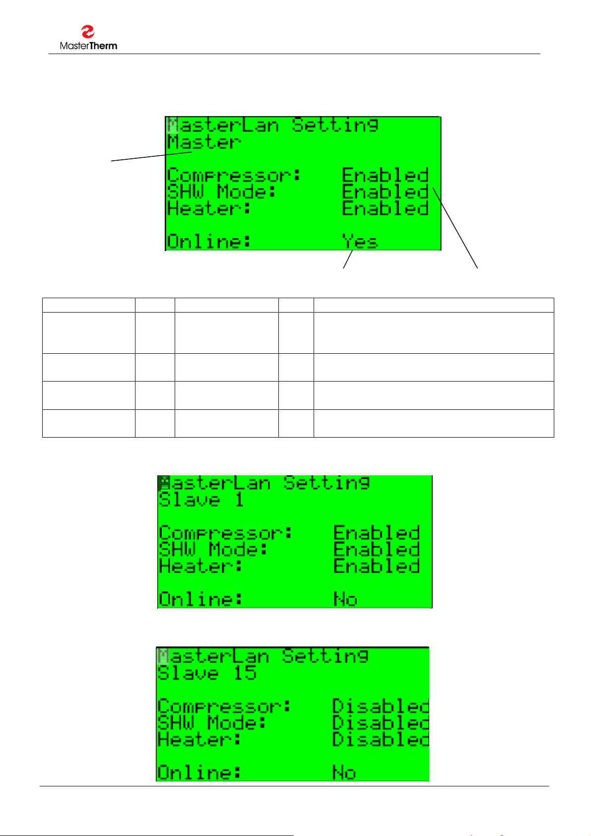
4.2.2 Master setting masks
Using keys UP and DOWN you have access to the following masks.
Unit in the MasterLAN
system
Master/Slave1/Slave2
/........./Slave15
Yes/No Enabled/Disabled
Parameter: SP Range/F.: Unit Description
Compressor B440
-455
SHW Mode - Enabled/Disabled
Heater B460
-475
Online - Yes/No - If the unit is communicating in MasterLAN
Similar masks appearing for each unit .........
Enabled/Disabled
F: Enabled
F: Enabled
Enabled/Disabled
F: Enabled
- Allows compressor to be controlled by
MasterLAN control in Heating/Cooling
mode.
- Unit is enabled for SHW Mode. When
Disabled, unit will not run in SHW Mode.
- Enabling heater for MasterLAN control in
heating mode.
network (unit is present and online).
.
.
.
Revison 1.1, Ing. Jiří Jiránek 10

MasterLAN –INSTRUCTION MANUAL
Parameter: SP Range/F.: Unit Description
Compressor
Control
Proportional
Band
Integration
Time
Derivative Time I137 0-9999
I133 P, PI, PID
F: P
A94 0.0-99.9
F: 3.0
I135 0-9999
F: 0
- Compressor control mode.
°C Control proportional band.
s Integration time of PI or PID control mode
s Derivative time of PID control mode
F: 0
Parameter: SP Range/F.: Unit Description
Rotation B409 FIFO/LIFO
F: FIFO
- Compressor rotation system
FIFO = first in, first out
LIFO = last in, first out
1 Compressor
Off Time
I139 0-999
F: 360
s Minimum compressor Off time. Minimum
time compressor must stay Off before
starting after stop command.
1 Comprressor
On Time
2 Compressors
Off Start
1 Compressor
Off Start
I141 0-999
F: 10
I143 0-999
F: .30
I145 0-999
F: .360
s Minimum time compressor must stay On
after start command.
s Minimum time between starts of 2 different
compressors.
s Minimum time between 2 starts of the same
compressor.
Revison 1.1, Ing. Jiří Jiránek 11

MasterLAN –INSTRUCTION MANUAL
Parameter: SP Range/F.: Unit Description
Heater Control I134 P, PI, PID
- Auxiliary heater control mode.
F: P
Proportional
Band
Integration
Time
Derivative Time I138 0-9999
A95 0.0-99.9
F: 3.0
I136 0-9999
F: 0
°C Heater Control proportional band.
s Integration time of PI or PID heater control
mode
s Derivative time of PID heater control mode
F: 0
Parameter: SP Range/F.: Unit Description
Rotation - FIFO/LIFO
F: FIFO
- Heater rotation system
FIFO = first in, first out
LIFO = last in, first out
1 Heater Off
Time
I140 0-999
F: 360
s Minimum heater Off time. Minimum time
heater must stay Off before starting after
stop command.
1 Heater On
Time
2 Heaters Off
Start
1 Heater Off
Start
I142 0-999
F: 10
I144 0-999
F: .30
I146 0-999
F: .360
s Minimum time heater must stay On after
start command.
s Minimum time between starts of 2 different
heaters.
s Minimum time between 2 starts of the same
heater.
Revison 1.1, Ing. Jiří Jiránek 12

MasterLAN –INSTRUCTION MANUAL
4.2.3 Source Control Masks
Source control allows cascade control according to the source temperature as well.
Parameter: SP Range/F.: Unit Description
Source Control
Enabled
Source Control
Active
Control Probe - B1-5/pCO5
Setpoint A434 -99.9 / +99.9
Real
Temperature
Compressors H I411 0-99 °C Requested Compressors Heating
Compressors S I412 0-99 °C Requested Compressors Source
Parameter: SP Range/F.: Unit Description
Source Control I410 P, PI, PID
Proportional
Band
Integration
Time
Derivative Time I409 0-9999
- Yes/No
- Enabling Source Control
F: No
B429 Yes/No - Source Control Active, Enabled + Probe OK
- Choice of Source Control probe.
B1-4/pCOe
F: Not Used
°C Source Control Setpoint
F: 5.0
A433 -99.9 / +99.9 °C Real Source Temperature
- Compressor Source control mode.
F: P
A529 0.0-99.9
°C Source Control proportional band.
F: 5.0
I408 0-9999
F: 0
s Integration time of PI or PID Source control
mode
s Derivative time of PID Source control mode
F: 0
Revison 1.1, Ing. Jiří Jiránek 13

MasterLAN –INSTRUCTION MANUAL
4.2.4 OFFLINE configuration
In case, unit losses bus communication with Master unit, it starts working in OFFLINE mode,
according to actual settings. It is possible to choose relay, activated in case of OFFLINE
situation.
Parameter: SP Range/F.: Unit Description
Master Online
Delay
Master Offline
Delay
Rele - Relay 1-8/pCO5
P - 0/1
Online B480 Yes/No - Master Online
Active B427 Yes/No - Master Online and MasterLAN control active
I406 0-999
F: 60
I407 0-999
F: 60
Relay 1-4/pCOe
F: Not Used
F: 0
s Delay of MasterLAN control activation, after
Master unit is Online.
s Delay of MasterLAN control deactivation,
after Master unit is Offline.
- Choice of relay activated, in case Master is
Offline.
- Master Offline Relay polarity
Revison 1.1, Ing. Jiří Jiránek 14

MasterLAN –INSTRUCTION MANUAL
4.2.5 Remote Functions
This is the setup of services used on Slave unit provided remotely by Master unit. Each Slave
could be set separately.
Parameter: SP Range/F.: Unit Description
Outdoor Probe:
Value:
SHW Probe:
Value:
SHW Mode:
Active
B203
B204
B205
-
0/1 (No/Yes)
F: 0 (No)
0/1 (No/Yes)
F: 0 (No)
0/1 (No/Yes)
F: 0 (No)
0/1 (No/Yes)
-
°C
-
°C
-
-
No = Slave unit uses own outdoor
temperature probe (recommended)
Yes = Slave unit uses outdoor temperature
probe from Master unit
Shows actual Master value
No = Slave unit uses own Hot Water
temperature probe
Yes = Slave unit uses Hot Water
temperature probe from Master unit
Shows actual Master value
This function is usable, when each unit has
its own Hot Water 3way valve or charging
pump.
No = Slave unit activates Hot Water mode
by its own control
Yes = Slave unit activates Hot Water mode
according to order from Master unit and by
its own control, if it is configured.
Shows actual Master value
Revison 1.1, Ing. Jiří Jiránek 15

MasterLAN –INSTRUCTION MANUAL
4.3 Control principle
Control automaticaly balances the operating hours and sequence of the compressors.
MasterLAN setpoint for compressors and heaters are automatically transferred from Master
unit. Although Slaves are switched On and Off via MasterLAN, they still keep they own setting.
Therefore Slaves setpoints must be highest possible for heating mode and lowes possible for
cooling mode.
4.3.1 Proportional control (recommended)
Proportional control works very simply. Proportional band is divided between compressor steps.
Proportional control is stable but always works with steady state error, so the system is not able
to reach exactly the setpoint. This is not a problem, cause compressors are controlled by On/Off
principle. Disadvantage is, that “band”is relatively big, cause You can not set band per one
compressor less than 1K. This could be the problem for more than 4 compressors.
Example:
Compressors: 4 Proportional band: 4 Requested temperature: 40 °C
Starting temperature: 30 °C
All compressors are running.
When the temperature reaches 37°C, 1st compressor is switched Off.
When the temperature reaches 38°C, 2nd compressor is switched Off.
When the temperature reaches 39°C, 3rd compressor is switched Off.
When the temperature reaches 40°C, the last compressor is switched Off.
Starting temperature: 40 °C
All compressors are Off.
When the temperature reaches 39°C, 1st compressor is switched On.
When the temperature reaches 38°C, 2nd compressor is switched On.
When the temperature reaches 37°C, 3rd compressor is switched On.
When the temperature reaches 36°C, the last compressor is switched On.
4.3.2 PI control
PI control is able to work almost without steady state error, but it’s more sensible for unstability.
It requires more time during commisioning for proper setting of the P and I constants.
Revison 1.1, Ing. Jiří Jiránek 16

MasterLAN –INSTRUCTION MANUAL
4.3.3 PID control
This is the best control method for the more than 4 compressors in the MasterLAN. In reality
You are able to have almost continuous and very accurate control of the requested water
temperature. Begin with the setting of the P/I/D = 50K / 100s / 10s.
If the systém is not stable, increase P.
5 Alarms MasterLAN masks
To find information about Slaves alarms, press ALARM button on the MasterLAN mask.
Press ALARM button to see Slaves alarm status......
Pressing the ENTER key You can edit and change Slave unit. After change for the Slave unit
please wait some time to allow the system to read the data from the Slave unit (30s
recommended).
If You press ALARM button on this mask, Master will send RESET command to all Slaves.
Revison 1.1, Ing. Jiří Jiránek 17

MasterLAN –INSTRUCTION MANUAL
6 Additional notes
• For heating mode all Slaves must have maximum water requested temperature settings
in the menu “Heating Set”, 47.5°C recommended both for point A and B.
- this is not neccessary from SW revision 33 (document revision 12)
• For cooling mode all Slaves must have minimum water requested temperature settings in
the menu “Cooling Set”, 14.5°C recommended both for point A and B.
• Control of the Sanitary Hot Water must be performed by Master unit only.
• All requested temperature settings must be done in the Master unit ONLY. (“Master”
displayed in the right top corner of the display in the ICON mask.
• Internet connection if it is used, must be in the Master unit.
7 Revision history
REV.10
REV 11
Source Control Mode
OFFLINE Management
REV 12
Remote Functions
Automatic maximum setpoint activation for slave units
Revison 1.1, Ing. Jiří Jiránek 18

MasterLAN –INSTRUCTION MANUAL
Revison 1.1, Ing. Jiří Jiránek 19

Registered trade marks and l
ogos used in the
MasterLAN –INSTRUCTION MANUAL
MASTERTHERM CZ s.r.o.
NOTES:
text are owned by the appropriate companies.
All rights are reserved.
Unauthorized modifications are not permitted.
Václavské náměstí 819/43, 110 00 Praha 1
tel.:+ 420 311 516 567
e-mail: info@mastertherm.cz, www.mastertherm.cz
 Loading...