

Master Spas NT MP FORCE, INT MP FORCE WITH WAVE XP, INT MP FORCE D, INT MP FORCE D WITH WAVE XP, INT MP SIGNATURE WITH WAVE XP Owner's Manual
...
OWNER’S MANUAL
INTERNATIONAL


1DO NOT DIVE.
MASTER SPAS OWNER’S MANUAL
Welcome To Ultimate Relaxation!
Thank you for choosing your new swim spa built by Master Spas. Please read the entire Owner’s
Manual before installing and using your swim spa. The goal of this manual is to provide you with
safety and operational information plus some tips that will help you enjoy your swim spa to its fullest.
At the time of print, this manual is accurate in its information. Master Spas reserves the
right to change or improve its product without prior notice. Please visit www.masterspas.com
to check for product information updates and click the Resources link on the page to review
support information.
Record Of Ownership
Name ��������������������������������������������������������������������������������
Address ������������������������������������������������������������������������������
City ��������������������������������������������������������� State ������ Zip ���������
Phone # (������)��������-���������� Date Purchased ������ /������ /�������
Model ��������������������������������� Serial # ���������������������������������������
Dealer Name �������������������������������������������������������������������������
Service Tech Rep ����������������������������������������������������������������������
Serial Number Location
The serial number for your swim spa is located near the filter area, on the swim spa system pack,
or on the listing plate on the skirting. It will start with “H” followed by a 6 digit number.
Ex. H171234
Register Your Swim Spa
Please be sure to register your swim spa so we can efficiently assist with any questions you may have.
Until your swim spa has been registered, Master Spas Inc. will not have record of your ownership.
To register your swim spa, visit www.MasterSpas.com and click the Resources link on the page. This
area will offer Swim Spa Registration capability along with other support information.
6927 Lincoln Parkway
Fort Wayne, Indiana 46804
www.masterspas.com

2DO NOT DIVE. 2
TABLE OF CONTENTS
Record of Ownership .............................................................................................................. 1
Table of Contents ................................................................................................................... 2
Safety Instructions ............................................................................................................ 3-10
VGB Suction Safety & Maintenance Instructions ............................................................... 11-12
Glossary of Swim Spa Terminology .................................................................................. 13-15
Site Preparation / General Guidelines .............................................................................. 16-18
Installation Instructions ........................................................................................................ 19
The Advantages of EcoPur
®
Charge .................................................................................. 20-21
Water Chemistry Terms You Should Know ....................................................................... 22-23
Why Are Chemicals Important in a Swim Spa ........................................................................ 24
Water Maintenance ......................................................................................................... 25-28
Start-Up ........................................................................................................................ 25
Schedule .................................................................................................................. 26-27
Troubleshooting Guide .................................................................................................. 28
Regular Maintenance Procedures ..................................................................................... 29-34
Swim Spa Troubleshooting Guide .................................................................................... 35-36
Winterizing & Storing Your Swim Spa ................................................................................... 37
Swim Spa Care & Maintenance Record ............................................................................. 38-40
Electrical Requirements ................................................................................................... 41-47
Model Specifications ............................................................................................................ 48
Swim Spa Controls .......................................................................................................... 49-65
Propulsion System Controls ............................................................................................. 66-76
Propulsion System Technical Information .............................................................................. 77
Fusion Touch Sound (if equipped) .................................................................................... 78-79
Deluxe Fusion BT Stereo Option (if equipped) .................................................................. 80-88
Mast3rPur (if equipped) .................................................................................................. 89-91
SoftTread
™
Floor System by SwimDek® (if equipped) ............................................................. 92

3DO NOT DIVE.
SAFETY INSTRUCTIONS
SAVE THESE INSTRUCTIONS
Included with your new swim spa is a safety sign. The sign is for you and your guest’s protection
and is suitable for outdoor use in wet locations. The sign should be placed in a location visible
to all users of the swim spa.
Please take time to point out the physical location of the safety sign and the importance of
the safety precautions displayed on the safety sign to all of your guests. Remember, your safety
and the safety of anyone who enjoys the use of your swim spa is our utmost concern.
The sign should be mounted with screws or another type of permanent fastener. Additional
or replacement signs can be obtained from your dealer or direct from the factory.
INTRODUCTION
It’s time to relax! You now have your very own portable swim spa by Master Spas, Inc. By fully
understanding the operation of each of the features of your new Master Spa, you will be assured
of many years of hassle-free, hot water therapy and fun.
Your safety is of paramount importance to the MasterSpas family. We urge you to read and
become thoroughly familiar with all safety aspects addressed in this manual.
Through reading and totally understanding the important information in your owner’s manual, you
will realize that you now own THE ULTIMATE RELAXATION MACHINE!

4DO NOT DIVE.
SAFETY INSTRUCTIONS
IMPORTANT SAFETY INSTRUCTIONS
When installing and using this electrical equipment, basic safety precautions should
be observed including the following:
READ AND FOLLOW ALL
INSTRUCTIONS
WARNING – To reduce the risk of injury, do not permit children to use this product
unless they are closely supervised at all times.
A wire conductor is provided on this unit to connect a minimum 6 AWG
(13.302mm
2
) solid copper conductor between this unit and any metal equipment,
metal enclosures of electrical equipment, metal water pipe, or conduit within 5 feet
(1.5m) of the unit
(For cord-connected/convertible units)
DANGER – Risk of injury.
a) Replace damaged cord immediately.
b) Do not bury cord.
c) Connect to a grounded, grounding type receptacle only.
(For units intended for indoor use only)
WARNING – For indoor use only. This unit is not intended for outdoor use.
(For units intended for outdoor use only)
WARNING – For outdoor use only. This unit is not intended for indoor use.

5DO NOT DIVE.
SAFETY INSTRUCTIONS
IMPORTANT SAFETY
INSTRUCTIONS (CONT.)
(For units with GFCI)
WARNING – This product is provided with a ground-fault circuit interrupter
located on the front panel of selected swim spas and on the power cord of
120 volt convertible spas. The GFCI must be tested before each use. With the
product operating, open the service door. When the product stops operating,
this merely indicates that the door is equipped with an electrical interlock.
Next, push the test button on the GFCI and close the service door. The product should not operate. Now open the service door, push the reset button
on the GFCI and close the service door. The product should now operate
normally. When the product fails to operate in this manner, there is a ground
current flowing indicating the possibility of an electric shock. Disconnect the
power until the fault has been identified and corrected.
DANGER – Risk of Accidental Drowning. Extreme caution must be exercised to prevent unauthorized access by children. To avoid accidents, ensure that children cannot use this swim spa unless they are supervised at all times.
DANGER – Risk of Injury. The suction fittings in this swim spa are sized to match
the specific water flow created by the pump. Should the need arise to replace the
suction fittings or the pump, be sure that the flow rates are compatible.
Never operate swim spa if the suction fittings are broken or missing. Never replace
a suction fitting with one rated less than the flow rate marked on the original suction fitting.
DANGER – Risk of Electric Shock. Install at least 5 feet (1.5m) from all metal surfaces. As an alternative, a swim spa may be installed within 5 feet of metal surfaces
if each metal surface is permanently connected by a minimum 8AWG (8.4mm
2
)
solid copper conductor to the wire connector on the terminal box that is provided
for this purpose.
DANGER – Risk of Electric Shock. Do not permit any electric appliance, such as a
light, telephone, radio, or television, within 5 feet (1.5 m) of a swim spa.
WARNING – To reduce the risk of injury:
a) The water in a swim spa should never exceed 40˚C (104˚F). Water tem-
peratures between 38˚C (100˚F) and 40˚C ( 104˚F) are considered safe for
a healthy adult. Lower water temperatures are recommended for young
children and when swim spa use exceeds 10 minutes.

6DO NOT DIVE.
SAFETY INSTRUCTIONS
IMPORTANT SAFETY
INSTRUCTIONS (CONT.)
b) Since excessive water temperatures have a high potential for causing fetal
damage during the early months of pregnancy, pregnant or possibly pregnant women should limit water temperatures to 38˚C (100˚F).
c) Before entering a swim spa, the user should measure the water tempera-
ture since the tolerance of water temperature- regulating devices varies.
d) The use of alcohol, drugs, or medication before or during swim spa use
may lead to unconsciousness with the possibility of drowning.
e) Obese persons and persons with a history of heart disease, low or high
blood pressure, circulatory system problems, or diabetes should consult a
physician before using a swim spa.
f) Persons using medication should consult a physician before using a swim
spa since some medication may induce drowsiness while other medication
may affect heart rate, blood pressure, and circulation.
(For swim spas with a gas heater)
WARNING – Risk of Suffocation. This swim spa is equipped with a gas heater
and is intended for outdoor use only unless proper ventilation can be provided for an indoor installation.
HYPERTHERMIA
Hyperthermia occurs when the internal temperature of the body reaches a
level several degrees above the normal body temperature of 98.6°F (37˚C).
THE SYMPTOMS OF HYPERTHERMIA INCLUDE:
• Dizziness • Fainting • Drowsiness • Lethargy
• Increase in Internal Body Temperature
THE EFFECTS OF HYPERTHERMIA INCLUDE:
Unawareness of Impending Hazard • Failure to Perceive Heat • Failure to
Recognize the Need to Exit Swim Spa • Physical Inability to Exit Swim Spa •
Fetal Damage in Pregnant Women • Unconsciousness Resulting in a Danger
of Drowning

7DO NOT DIVE.
SAFETY INSTRUCTIONS
IMPORTANT SAFETY
INSTRUCTIONS (CONT.)
DANGER – To reduce the risk of injury to persons, do not remove the suction
grate. Suction through drains and skimmers is powerful when the jets in the swim
spa are in use. Damaged covers can be hazardous to small children and adults with
long hair. Should any part of the body be drawn into these fittings, turn off the
swim spa immediately. As a precaution, long hair should not be allowed to float in
the swim spa.
WARNING – Install the swim spa so that water can be easily drained out of the
compartment containing electrical components so as not to damage equipment.
When installing the swim spa make sure to allow for an adequate drainage system to deal with any overflow water. Please allow for at least 3 feet of clearance
around the perimeter of the swim spa to provide enough room to access for servicing. Contact your local dealer for their specific requirements.
WARNING – The swim spa should be covered with an approved locking cover
when not in use, to prevent unauthorized entry and injuries.
WARNING – People with infections, sores or the like should not use the swim spa.
Warm and hot water temperatures may allow the growth of infectious bacteria if
not properly disinfected.
CAUTION – Safe temperatures for swimming or aquatic exercise is around 80˚F
(26.7˚C).
CAUTION – Risk of Electrical Shock. Do not leave audio compartment open.
Audio CD controls are not to be operated while inside the swim spa.
CAUTION – Replace components only with identical components.
WARNING – Risk of Electric Shock. Do not connect any auxiliary components (for
example, additional speakers, headphones, additional audio/ video components
etc.) to the system. These units are not provided with an outdoor antenna.
Do not service this product yourself as opening or removing covers may expose
you to dangerous voltage or other hazards. Refer all servicing to qualified service
personnel.
If the power supply cord(s) are damaged, water is entering the speaker, audio
compartment, or any other component in the electrical equipment compartment
area, the protective shield is showing signs of deterioration, or there are signs of
other potentially hazardous damage to the unit, turn off the circuit breaker from
the wall and refer servicing to qualified personnel.

8DO NOT DIVE.
SAFETY INSTRUCTIONS
IMPORTANT SAFETY
INSTRUCTIONS (CONT.)
The unit should be subjected to periodic routine maintenance once every quarter to
make sure that the it is operating properly.
DANGER – Risk of Electric Shock. A green colored terminal or a terminal marked G,
GR, Ground, Grounding or the symbol shown in Figure 14.1 of UL 1563 is located
inside the supply terminal box or compartment. To reduce the risk of electric shock,
this terminal must be connected to the grounding means provided in the electric
supply service panel with a continuous copper wire equivalent in size to the circuit
conductors supplying this equipment.
At least two lugs marked “Bonding Lugs” are provided on the external surface or
on the inside of the supply terminal box or compartment. To reduce the risk of
electric shock, connect the local common bonding grid in the area of the swim spa
to these terminals with an insulated or bare copper conductor not smaller than
8AWG.
All field installed metal components such as rails, ladders, drains, or other similar
hardware within 3m of the swim spa shall be bonded to the equipment grounding
bus with copper conductors not smaller than 8AWG.
SAVE THESE INSTRUCTIONS

9DO NOT DIVE.
SAFETY INSTRUCTIONS
WARNING: CHILDREN SHOULD NOT USE SWIM SPAS OR HOT TUBS WITHOUT ADULT
SUPERVISION
AVERTISSEMENT: NE PAS LAISSER LES ENFANTS UTILISER UNE CUVE DE RELAXATION
SANS SURVEILLANCE
WARNING: DO NOT USE SWIM SPAS OR HOT TUBS UNLESS ALL SUCTION GUARDS ARE
INSTALLED TO PREVENT BODY AND HAIR ENTRAPMENT.
AVERTISSEMENT: POUR ÉVITER QUE LES CHEVEUX OU UNE PARTIE DU CORPS
PUISSENT ÊTRE ASPIRES, NE PAS UTILISER UNE CUVE DE RELAXATION SI LES GRILLES DI PRISE
D’ASPIRATION NE SONT PAS TOUTES EN PLACE
WARNING: PEOPLE USING MEDICATIONS AND/OR HAVING AN ADVERSE MEDICAL HIS-
TORY SHOULD CONSULT A PHYSICIAN BEFORE USING A SWIM SPA OR HOT TUB.
AVERTISSEMENT: LES PERSONNES QUI PRENNENT DES MÉDICAMENTS OU ONT
DES PROBLÉMES DE SANTÉ DEVRAIENT CONSULTER UN MÉDECIN AVANT D’UTILISER UNE CUVE
DE RELAXATION
WARNING:
PEOPLE WITH INFECTIOUS DISEASES SHOULD NOT USE A SWIM SPA OR HOT TUB
AVERTISSEMENT: LES PERSONNES ATTEINTES DE MALADIES INFECTIEUSES NE
DEVRAIENT PAS UTILISER UNE CUVE DE RELAXATION
WARNING: TO AVOID INJURY EXERCISE CARE WHEN ENTERING OR EXITING THE SWIM
SPA OR HOT TUB.
AVERTISSEMENT: POUR ÉVITER DES BLESSURES, USER DE PRUDENCE EN ENTRANT
DANS UNE CUVE DE RELAXATION ET EN SORTANT
WARNING: DO NOT USE DRUGS OR ALCOHOL BEFORE OR DURING THE USE OF A SWIM
SPA OR HOT TUB TO AVOID UNCONSCIOUSNESS AND POSSIBLE DROWNING
AVERTISSEMENT: POUR ÉVITER L’ÉVANOUISSEMENT ET LA NOYADE ÉVENTUELLE, NE
PRENDE NI DROGUE NI ALCOOL AVANT D’UTILISER UNE CUVE DE RELAXATION NI QUAND ON S’Y
TROUVE
WARNING: PREGNANT OR POSSIBLY PREGNANT WOMEN SHOULD CONSULT A PHYSI-
CIAN BEFORE USING A SWIM SPA OR HOT TUB.
AVERTISSEMENT: LES FEMMES ENCEINTES, QUE LEUR GROSSESSE SOIT CONFIRMÉE
OU NON, DEVRAIENT CONSULTER UN MÉDECIN AVANT D’UTILISER UNE CUVE DE RELAXATION
WARNING: WATER TEMPERATURE IN EXCESS OF 38˚C MAY BE INJURIOUS TO YOUR
HEALTH
AVERTISSEMENT: IL PEUT ÊTRE DANGEREUX POUR LA SANTÉ DE SE PLONGER DANS
DE L’EAU A PLUS DE 38˚C
WARNING: BEFORE ENTERING THE SWIM SPA OR HOT TUB MEASURE THE WATER TEM-
PERATURE WITH AN ACCURATE THERMOMETER
AVERTISSEMENT: AVANT D’UTILISER UNE CUVE DE RELAXATION MESURER LA
TEMPÉRATURE DE L’EAU À L’AIDE D’UN THERMOMÉTRE PRÉCIS

10DO NOT DIVE.
SAFETY INSTRUCTIONS
WARNING: DO NOT USE A SWIM SPA OR HOT TUB IMMEDIATELY FOLLOWING STRENU-
OUS EXERCISE
AVERTISSEMENT: NE PAS UTILISER UNE CUVE DE RELAXATION IMMÉDIATEMENT
APRÉS UN EXERCISE FATIGANT
WARNING: PROLONGED IMMERSION IN A SWIM SPA OR HOT TUB MAY BE INJUROUS TO
YOUR HEALTH
AVERTISSEMENT: L’UTILISATION PROLONGÉE D’UNE CUVE DE RELAXATION PEUT
ÊTRE DANGEREUSE POUR LA SANTÉ
WARNING: DO NOT PERMIT ELECTRIC APPLIANCES (SUCH AS LIGHT, TELEPHONE, RADIO,
OR TELEVISION) WITHIN 1.5 M OF THIS SWIM SPA OR HOT TUB
AVERTISSEMENT: NE PAS PLACER D’APPAREIL ÉLECTRIQUE (LUMINAIRE, TÉLÉPHONE,
RADIO, TÉLÉVISEUR, ETC) À MOINS DE 1.5 M DE CETTE CUVE DE RELAXATION
CAUTION: MAINTAIN WATER CHEMISTRY IN ACCORDANCE WITH MANUFACTURER’S
INSTRUCTION
ATTENTION: LA TENEUR DE L’EAU EN MATIÉRES DISSOUTES DOIT ÊTRE CONFORME AUX
DIRECTIVES DU FABRICANT
Hyperthermia occurs when the internal temperature of the body reaches a level several degrees
above the normal body temperature of 37˚C (98.6˚F). The symptoms of hyperthermia include
drowsiness, lethargy, and an increase in the internal temperature of the body. The effects of hyperthermia include
(a) unawareness of impending hazard;
(b) failure to perceive heat;
(c) failure to recognize the need to exit swim spa;
(d) physical inability to exit swim spa;
(e) fetal damage in pregnant women; and
(f) unconsciousness and danger of drowning.
WARNING: THE USE OF ALCOHOL OR DRUGS CAN GREATLY INCREASE THE RISK OF
FATAL HYPERTHERMIA IN HOT TUBS AND SWIM SPAS
LA CONSOMMATION D’ALCOOL OU DE DROGUE AUGMENTE CONSIDÉRABLEMENT LES
RISQUES D’HYPERTHERMIE MORTELLE DANS UNE CUVE DE RELAXATION.

11DO NOT DIVE.
VGB Suction Safety &
Maintenance Instructions
VGB 2008:
WARNING
Read and follow all instructions in this manual and on the suction fitting. Failure to follow
instructions can cause severe injury and/or death.
Failure to remove pressure test plugs and/or plugs used in winterization of the spa/swim
spa from the suction outlets can result in an increased potential for suction entrapment as
described on the previous page.
Suction outlet components have a finite life. The cover/grate should be inspected frequently and replaced at least every seven years, or if found to be damaged, broken, cracked,
missing, or not securely attached.
If the fitting is missing or broken, replace with a fitting of equivalent rating or higher. Use
of a lower rated suction fitting could result in entrapment of the body which could result
in serious injury including drowning.
Do not use or operate spa/swim spa if this suction fitting is missing, broken or not secured
per instructions. The suction fitting is intended to prevent entrapment of the body. Use of
the spa/swim spa with a missing, broken or improperly secured suction grate may result in
serious personal injury including drowning.
When the spa/swim spa is in operation, suction is created at this fitting. Users of the spa/
swim spa must be instructed not to come in contact with this fitting in such a way as to
block its orifice. If a user of the spa/swim spa blocks this fitting with his/her body, serious
personal injury or drowning may occur.
IMPORTANT SAFETY INSTRUCTIONS
WARNING - SUCTION ENTRAPMENT HAZARD
Suction in suction outlets and/or suction outlet covers which are damaged, broken,
cracked, missing, or unsecured can cause severe injury and/or death due to the following entrapment hazards:
Hair Entrapment: Hair can become entangled in suction outlet cover.
Limb Entrapment: A limb inserted into an opening of a suction outlet sump/fitting or suction outlet
cover that is damaged, broken, cracked, missing, or not securely attached can result in a mechanical bind or swelling of the limb.
Body Suction Entrapment: A negative pressure applied to a large portion of the body or limbs can
result in an entrapment.
Evisceration / Disembowelment Entrapment: A negative pressure applied directly to the intestines
through an unprotected suction outlet sump or suction outlet cover which is damaged, broken,
cracked, missing, or unsecured can result in evisceration / disembowelment entrapment.
Mechanical Entrapment: There is potential for jewelry, swimsuit, hair decorations, finger, toe, or
knuckle to be caught in an opening of a suction outlet cover resulting in mechanical entrapment.

12DO NOT DIVE.
VGB Suction Safety &
Maintenance Instructions
TO REDUCE THE RISK OF ENTRAPMENT HAZARDS:
• Never use a spa/swim spa if any suction outlet component is damaged, broken, cracked, missing,
or not securely attached.
• Replace damaged, broken, cracked, missing, or not securely attached suction outlet components
immediately.
• It is recommended that suction components be inspected at least monthly.
• Replace the suction within 7 years from the installation date. Contact your dealer or local service
center for quoting and scheduling this required maintenance. This is a mandated regulation and
is not part of nor covered by the spa/swim spa warranty.
NOTE: Always review entire safety and maintenance information before beginning maintenance.
Contact Master Spas for Suction Installation information for complete suction assembly replacement.

13DO NOT DIVE.
GLOSSARY OF SWIM SPA TERMINOLOGY
Your new Master Spa features a variety of jets. All jets, regardless of style return the water to the
swim spa. Air is mixed with the water by using the air controls (if equipped) creating a gentle to
most vigorous massage. Water flow is adjusted by simply turning the outer face of most jets. Your
Master Spa may have a combination of pulsating, rotating, dual pulsating and directional adjustable jets.
1. THERAPY JETS
Located throughout the seats of the swim spa to offer a variety of therapy combinations.
2. NECK JETS (if equipped)
Located above the normal water level to provide massaging action to the back of the neck.
3. SHOULDER JETS (if equipped)
Located above the normal water level to provide massaging action to the shoulders.
4. MASTER BLASTER FOOT THERAPY JET (if equipped)
Large jet with several fixed nozzles located in the bottom of the swim spa near the floor to provide excellent massage to the feet.
5. JET DIVERTER VALVE (if equipped)
Located on the top flange of the swim spa, this large valve physically diverts the flow of water
from one group of jets to another. Be sure that no sand or particles are brought into the swim
spa as they will cause the diverter to seize up. It is best to turn the diverter valve only when the
pump is turned off.
6. WATER FEATURE VALVE (if equipped)
Located on the top flange of the swim spa, this smaller valve adjusts water flow to the water-
falls and/or water features in your swim spa.
NOTE:
When the swim spa is not in use, this valve should be turned mostly shut (not completely
shut) to prevent the water features from allowing water to hit the cover while it is closed.
If left mostly open, water may hit the cover and possibly run out of the swim spa causing
water loss.
7. AIR CONTROL VALVE
These smaller valves are located around the top of your swim spa. You may increase or decrease
the force of your jets by opening or closing the air control valves. Each air control valve will typically function 1 to 2 groups or seats of jets in the swim spa. When not in use the air controls
should be kept in the closed position as the air being introduced in to the water can tend to
cool the water and increase the dissipation rate of sanitizer levels.
8. TOPSIDE CONTROL PANEL
You may safely control swim spa functions from inside or outside your swim spa using the
Topside Control Panel. This Panel is used to control the water temperature, pumps, the swim
spa light, automatic filtration cycles and other advanced functions. The digital display will give
you a constant temperature readout and will notify you in case of certain malfunctions. Several
user programmable functions are also available.

14DO NOT DIVE.
GLOSSARY OF SWIM SPA TERMINOLOGY
9. PERSONAL REMOTE CONTROL (if equipped)
Select swim spa models may have an additional remote which allows the user to control the
jet therapy while remaining in the seat (if applicable). By pressing the control one time, you
will activate the pump. Press again for high speed and again to turn it off.
10. ACCESS PANELS
These are the skirt panels located
around all four sides of the swim spa.
All of the skirt panels are removable
should service be required. Master Spas
recommends at least 3 feet of access be
provided around the swim spa.
Panel “B”
Panel “H” Panel “G” Panel “F”
Panel “E”
Panel “A”
Panel “C” Panel “D”
11. EQUIPMENT ACCESS PANEL
This is the skirt panel located below the Topside Control Panel or behind access panel “A”.
This area houses the majority of components responsible for the swim spa’s operation. These
components include the pumps, heater, swim spa control system, ozonator (if equipped), and
LED light system (if equipped). Pump and equipment placement may vary by model.
12. FILTER LID
This lid fits over the filter area and weir gate to cover the filters. Remove filter lid to access
filters for maintenance.
13. WEIR GATE
The weir gate is the horizontal door located in front of the filters that helps keep debris
trapped in the filter area
14. SWIM SPA CONTROL SYSTEM
This houses the wiring and electrical components necessary to operate the swim spa.
15. SWIM SPA HEATER
This is an electric heater housed in a stainless steel tube. It is thermostatically controlled and
equipped with high-limit temperature safety shut-off sensors.
16. SLICE VALVES
These valves are used by service personnel to shut off water to the
heating system (heater and pump plumbed to the heater) so that
the swim spa water does not need to be drained if the swim spa
requires service to the heating system (varies by model).
NOTE: Slice valves must be completely open during normal operations.
17. MAIN THERAPY PUMP
This produces water flow through the main jets in the swim spa. The first pump may be oper-
ated on two speeds (varies by model). Low speed (if applicable) will produce efficient water
circulation during filtration, heating of the swim spa water, and gentle jet action. High speed
provides maximum jet action. The main pump is controlled by the “Jets” or “Jets I” button on
the Topside Control Panel.
Slice Valve and Pump Union

15DO NOT DIVE.
GLOSSARY OF SWIM SPA TERMINOLOGY
18. SECONDARY THERAPY PUMP (if equipped)
This produces water flow through 1 to 2 groups or seats of jets in the swim spa. The second
pump operates similar to the main pump and is controlled by the “Jets II” or “Aux” button
on the Topside Control Panel.
19. THIRD THERAPY PUMP (if equipped)
This produces water flow through 1 to 2 groups or seats of jets in the swim spa. This is con-
trolled by the Jets III button on the Topside Control Panel.
20. CIRCULATION PUMP (if equipped)
This produces water flow through the heater in the swim spa and provides the water flow
necessary to actuate the ozone injector. This energy efficient pump runs 24 hours for efficient
filtration and heating.
21. PUMP UNION
These are used to help relieve possible pump air locks or for service personnel to easily service
the pumps.
22. HEATER UNION
These are used by service personnel to easily service the heater.
23. SWIM SPA LIGHT
The on/off control for the lighting in your swim spa is located on the topside control panel near the
therapy seats.
24. EXERCISE JETS (H2X Swim Spas)
These large jets are grouped at the end of your swim spa to offer water flow for exercising
against. A jet diverter valve may control the flow for these jets.
25. SWIM SPA JUNCTION BOX (MP Swim Spa Only)
The internal junction box for connecting your electrical service(s) to the swim spa is located
behind and accessible by removing access panels “B” and “A”.
26. PROPULSION SYSTEM ACCESS (MP Swim Spa Only)
The propulsion control system of the MP Swim Spas is located behind the skirt panel desig-
nated as “E” in the access panels drawing. The propulsion motor, propulsion control pack,
and pulleys for the system are located in this area.
27. PROPULSION SYSTEM CONTROL PANEL (MP Swim Spa Only)
You may safely control the speed of the propulsion system from the inside of your swim spa
by using the buttons on the control panel mounted in the swim area. This control panel is
used to turn the propulsion system on and off and to adjust the intensity of the water flow.
Your swim spa may have one of three propulsion systems depending on the equipment
option: Wave, Wave XP, or Wave XP Pro. All three systems operate in the same manner using
the control panel mounted on the swim end of your swim spa. This control panel may be
safely used from inside or outside of the swim spa to operate the propulsion system.

16DO NOT DIVE.
SITE PREPARATION / GENERAL GUIDELINES
Swim spa installation is simple when properly planned. It is important that you read the following
information carefully and consult with your Master Spas dealer.
1) Access - The actual dimensions of your new swim spa will determine the amount of space that
is needed in moving the swim spa from curbside to its final installation area. Be sure to consider
and measure side yard dimensions, gates, doors, overall room dimensions and vertical obstructions such as ceilings, roof overhangs, balconies and overhead cables. Any other space limiting
obstacles such as stairs, trees, and shrubs must also be evaluated. Please be sure to contact and
review these site and installation plans with your Master Spas dealer prior to delivery.
2) Surface/Pad Requirements - When your new swim spa is filled with water and bathers, it may
weigh as much as several tons. It is imperative that the base beneath the swim spa can support
the entire weight. The swim spa must be on a uniformly firm, continuous, and level surface. The
recommended foundation is a concrete pad with a minimum thickness of four (4) inches with
steel reinforcement bars crossed throughout the pad.
IMPORTANT
When installing your swim spa indoors, on a wood deck, roof or balcony; load requirements need
to be evaluated before installation. You should speak with a qualified contractor or your local
building department to confirm that your surface is adequate for supporting a swim spa.
All sides of the swim spa must be accessible for regular maintenance or in the event that service
is needed. Periodical maintenance checks require entry into the equipment bay. When possible, it
is wise planning for the future to leave 3 feet of access to all sides of the swim spa in the event
your swim spa requires maintenance. Your swim spa warranty does not cover the cost of providing
access for service.
GENERAL CONSIDERATIONS FOR OUTDOOR INSTALLATION
Again, proper planning will increase your total enjoyment factor with your new swim spa. Listed
below are some additional items to consider when planning your installation.
• How swim spa will complement landscaping
and vice versa
• View from inside swim spa and view of swim
spa from inside of home
• Exposure to sunlight and shading from trees
• Privacy
• Getting to swim spa from house and return
• Proximity to dressing rooms and bathrooms
• Storage for swim spa chemicals
• Local building codes (if applicable)
• Power cable
GENERAL CONSIDERATIONS FOR INDOOR INSTALLATION
Installing your swim spa indoors creates an entirely different set of considerations.
• Work with your Master Spas dealer and
contractor to insure all local building, electrical and plumbing codes are met
• Plan for a floor drain to drain off excess water
and for draining and cleaning your swim spa
• A ventilation fan may be necessary due
to high humidity created by your swim spa
• Finished material in your swim spa room
should also be capable of withstanding
increased humidity

17DO NOT DIVE.
SITE PREPARATION / GENERAL GUIDELINES
GUIDELINES FOR PARTIALLY OR FULLY RECESSED INSTALLATION
Swim Spas manufactured by Master Spas, Inc. are designed to be installed in a variety of settings.
One of which is installing below grade. Should a swim spa be installed below the level of the
site drainage system (below grade), a system for preventing water collecting and pooling must be
designed based on the requirements of the local authority having jurisdiction. The drainage system
must be designed based on things such as rainfall, water runoff, splashing, draining the swim spa,
etc. that could potentially feed the below grade area with water. Where located in designated
floodways, additional attention to maximum water load entering the area below grade must be
addressed to prevent water from accumulating below grade at all times. It is generally recommended that the swim spa be installed above grade because the swim spa is not designed to be
submerged in water. When a proper drainage system is designed and proper ventilation is planned
based on the characteristics of the site, installing the swim spa below grade is an accepted method
of installation.
• The unit is self-supporting when placed on a surface designed to support the full load of the
swim spa (see Surface/Pad Requirements). Do not backfill with sand, gravel, or earth. Doing so
will void the warranty.
• Plan for complete drainage so that water accumulation drains away from the swim spa perimeter
and standing water never reaches the electrical equipment.
• Plan for appropriate ventilation to remove moisture accumulation and prevent equipment
overheat.
• Provide a minimum of 3 feet service area around the perimeter of the unit. Site access issues are
not covered by the product warranty.
• The unit is not designed to be submerged in water. Water entering the equipment area creates
many hazards and resulting damage will not be covered by the product warranty.
• Make sure that the surroundings do not create any additional hazards.
• Surfaces placed around the unit should also be evaluated for walking/slipping hazards from
standing water. Proper drainage is vital to the installation of a below grade installation.
• Check all building, electrical, and plumbing codes with the authority having jurisdiction to ensure
that your installation is in compliance with all local codes.
• Additional consideration needs to be made when installing unit in designed floodways.
• Verify that site specific drainage systems such as down spouts are not going to feed the area
below grade.
• Below grade drainage system needs to be evaluated based on area specific rainfall. One size
does not fit all so an analysis by a qualified, local engineer to ensure proper drainage of all sources of water is a must when installing below grade.

18DO NOT DIVE.
SITE PREPARATION / GENERAL GUIDELINES

19DO NOT DIVE.
INSTALLATION INSTRUCTIONSINSTALLATION INSTRUCTIONS
1. Put swim spa in final position that allows for access to equipment and swim spa components.
2. Remove skirt panels to access the electrical connections inside the swim spa. The junction box
(MP Swim Spas Only), swim spa control system(s) and majority of the equipment in your swim
spa can be accessed by removing access panels “A” and “B”.
Slice Valve and Pump Union
3. Be sure all pump and heater unions are secure. Each pump has
2 unions and the heater has 2 unions. A newly delivered swim
spa may have loose unions caused in transporting the swim
spa. Check that all slice valves are open, in the up position. The
slice valves may become closed during transportation of the
swim spa.
4. Fill the swim spa to the “minimum safe water level” sticker. This sticker is typically located
on the shell of the swim spa near the filter area. On the Momentum swim spa model with a
clear acrylic divider, it is recommended that the swim side be filled first and then the spa side.
When draining the swim spa always drain the spa side before draining the swim side.
5. Turn on power to the swim spa. If your swim
spa is equipped with two electrical supplies,
make sure that they are both turned on. The
swim spa will go through its priming mode.
This lasts approximately 5 minutes. The purpose of the priming mode is to help insure
that the jet pumps have been primed with
water and are ready to operate. It may be necessary in some instances to bleed air from the
jet pumps in your swim spa, if after the priming mode the swim spa pumps run but do not
move water the pump may have an air lock.
Due to the nature of water flow and hydro-therapy pumps, please be advised that air locking
of pumps may occur. Master Spas, Inc. has taken measures to reduce the possibility of this,
but it still may occur, especially after filling the swim spa. This is not a service covered by the
warranty and service charges may apply.
To relieve an airlock situation, loosen the pump union on the discharge of the pump. This
pump union is indicated by an arrow in the picture above. Water should leak out of the union
once the air has been removed. Tighten the union and test the pump for proper operation.
Repeat this process if needed.
NOTE: Upon power up, the propulsion system may mix water with air for up to several min-
utes until all of the air is pulled from the propulsion chamber. The propulsion system may be
noisy during this time. This is normal.
6. Be sure the jets in your swim spa are open.
7. Adjust water chemistry according to the instructions provided in the “Water Maintenance”
section.
8. Your swim spa water will heat approximately 1°F (0.5°C) per hour with the cover closed, on
average. Times may vary.
Airlock
Pump Union
Slice Valve

20DO NOT DIVE.
The EcoPur® Charge is made from Master Spa’s patented filtration fabric. This fabric is wound
tightly into a nautilus master core, creating a catalytic cell. The nautilus fabric cell is encased by a
unique “spring core” that allows for maximum flow and water “charging”. As water
comes in contact with the EcoPur® Charge Master Core, a chemical reaction causes zinc and copper hydroxides to form in controlled amounts. Like Mother Nature, when controlled releases of
copper and zinc oxides are carried into the filtered water, they kill bacteria and provide hostile
conditions for algae and fungal growth. Using EcoPur® Charge helps reduce the amount of chemicals needed, therefore safeguarding the hot tub’s plumbing and equipment because pipes are protected against the corrosive effects of chlorine. EcoPur® Charge Master Core Technology, another
exclusive design by Master Spas.
FEATURES
• Releases Sanitizing Copper & Zinc Oxides
• Reduces Water Soluble Heavy Metals
• Controls Scale, Bacteria And Algae
• Safeguards The Swim Spa’s Plumbing
• Reduces Use Of Chemicals
• Helps Prevent Damage To Swimwear
THE ADVANTAGES OF EcoPur® Charge
PATENTS PENDING
MADE IN
THE USA

21DO NOT DIVE.
ECOPUR® CHARGE INSTALLATION
THE ADVANTAGES OF EcoPur® Charge
Step 1: Insert EcoPur® Charge in to outer filter.
Step 2: Twist EcoPur
®
Charge clockwise to lock in place
while holding on to outer filter. When snapped in to
locked position, EcoPur® Charge handle aligns with
molded points on outer filter.
NOTE: EcoPur
®
Charge should be replaced every 6
months. Initial snap in fit of inner EcoPur® Charge to
outer filter may be tight, especially if both are new.
Master Spas Outer Filter
Turn Clockwise to Lock
EcoPur® Charge
PATENTS PENDING
MADE IN
THE USA

22DO NOT DIVE.
WATER CHEMISTRY TERMS YOU SHOULD KNOW
Before jumping into Water Maintenance, here are some terms to help you.
1. Parts per million, or ppm: This is a form of measurement used in most pool or swim spa
chemical readings. Best described as any one million like items of equal size and make up,
next to one unlike item, but of equal size. This would be one part per million.
3. Total Alkalinity: This is a measurement of the ability of the water to resist changes in pH.
Put another way, it is the water’s ability to maintain proper pH. Total alkalinity is measured
in parts per million from 0 to 400 plus, with 100 to 120 ppm being the best range for swim
spas. With low alkalinity, the pH will flip, or change back and forth, and be hard to control.
With high alkalinity it becomes extremely difficult to change the pH.
4. pH or potential hydrogen: This is a measurement of the active acidity in the water, or it is
the measurement of the concentration of active hydrogen ions in the water. The greater the
concentration of active hydrogen ions, the lower the pH. pH is not measured in parts per
million, but on a scale from 0 to 14, with 7 being the neutral. The pH in swim spas should
be ideally maintained between 7.4 to 7.6. It should never be below 7.2 or above 7.8. With
low pH, the results can be corroded metals, etched and stained plaster stained fiberglass or
acrylic, eye / skin irritation, rapid chlorine or bromine loss, and total alkalinity destruction.
With high pH, the results can be cloudy water, eye / skin irritation, scale formation and poor
chlorine or bromine efficiency.
5. Shocking: This is when you add either extra chlorine (superchlorinate) by raising the chlorine
level above 8 ppm, or add a non-chlorine /oxidizer (potassium monoperoxysulfate or potassium monopersulfate) to burn off the chloramines or bromamines. A non-chlorine /oxidizer acts
by releasing oxygen in the water, which serves the same function as chlorine. The advantage
to using non-chlorine /oxidizer, is you can enter the water within 15 minutes after application.
Using chlorine, you must wait until the total chlorine reading is below 5 ppm. One thing to
remember, a non-chlorine /oxidizer will not kill bacteria or disinfect.
6. Sequestering: This can be defined as the ability to form a chemical complex which remains in
solution, despite the presence of a precipitating agent (i.e. calcium and metals). Common
names for sequestering chemicals are; minquest, stain and scale control, metal-x, spa defender, spa metal gone, (etc.).
7. Filtration: Filters are necessary to remove particles of dust, dirt, algae, etc. that are continuously entering the water. If the swim spa is not operated long enough each day for the filter
to do a proper job, this puts a burden on the chemicals, causing extra expense. Filtration time
will depend on the water capacity, pump and filter size and, of course, bather load. Spare
filter cartridges should be kept on hand to make it easy to frequently clean the cartridge
without the need for a long shut down. This will also allow the cartridge to dry out between
usages, which will increase the cartridge life span as much as twice. Replace the cartridge
when the pleats begin to deteriorate. Cartridge cleaning should be done a minimum of once
a month. More often with a heavy bather load.

23DO NOT DIVE.
8. Sanitizers: This is what kills the germs and bacteria that enter the water from the environment
and the human body.
A. Chlorine
1. Only one type is approved for swim spa use. Sodium dichlor which is granular, fast
dissolving and pH neutral chlorine.
2. Chlorine is an immediate sanitizer and will be added as needed to maintain free chlo-
rine levels between 2.0 to 4.0 ppm..
B. Bromine (Note: Bromine use is not recommended with Eco Pur filters.)
1. Two types of tablets.
a. Hydrotech
b. Lonza
2. Bromine is a slow dissolve chemical and may take a few days to develop a reserve
or reading in the water. Bromine levels should be maintained between 2.0 to 4.0
ppm.
9. Total dissolved solids (TDS): Materials that have been dissolved by the water. i.e. Like what
happens when you put sugar in coffee or tea.
10. Useful life of water (in days): Water should be drained at least once every 180 days. Useful life
may vary by usage and bather load.
11. Defoamer: Foaming may be caused by body oils, cosmetics, lotions, surface cleaners, high
pH or algeacides as well as other organic materials. Low levels of calcium or sanitizer can
also cause foaming. Also, double rinse your bathing suits as they will hold residual soap after
being washed.
12. Calcium hardness: Water that is too hard (over 250 ppm) can promote scale formation in
components and on swim spa surface. Water that is too low (below 150 ppm) may also
shorten the life of metal components on the swim spa.
NOTE: Always leave swim spa cover open for 15 minutes after adding chemicals to prevent
the off gas from damaging your swim spa cover, swim spa pillows, stainless steel hardware
and other critical parts.
WATER CHEMISTRY TERMS YOU SHOULD KNOW

24DO NOT DIVE.
WHY ARE CHEMICALS IMPORTANT IN A SWIM SPA
1. Evaporation:
As water evaporates, only pure water evaporates, leaving the salts, minerals, metals, and any
unused chemicals behind. Adding water adds more salts, minerals, and metals. In time, the
water can become saturated with these dissolved solids and can cause stains or scale to form
on the walls of the swim spa or a scale build up inside the equipment. Colored or cloudy
water, and possible corrosion of plumbing and fittings may also occur.
2. Heat:
Heat causes much quicker evaporation and also will cause minerals and metals to precipitate
out of solution.
3. Air:
Dust and other airborne contaminants are introduced into the swim spa.
4. Environment:
The environment surrounding the swim spa can also impact the water quality. Items such as
pollen, grass, sand, dirt, lawn fertilizer, airborne dust, insects, leaves, and pets can all affect
the water quality of the swim spa.
5. Bathers:
As the swim spa is used, bathers introduce contaminants to the water. Increased bather
load, length of use and frequency will increase the amounts of contaminants added in to the
water.
Remember:
The maintenance routines set forth in this manual may need to be adjusted depending on bather
load and how much the swim spa is being used.

25DO NOT DIVE.
Step 1: Your swim spa should be filled using a Pre-filter, which can be obtained from your local
dealer. This Pre-filter will help remove many of the minerals existing in the water,
which will make adjusting the water balance easier after a new fill. Never use more
then 50% softened water when filling the swim spa.
Step 2: During the initial filling of the swim spa, add a sequestering agent to combat sus-
pended minerals in the water. The agents are sold under many different names such as
Mineral Clear, or Metal Protect. Allow water to circulate and filter for at least 30 minutes (or per bottle recommendations) before adding any other chemicals.
Step 3: Test water for pH, total Alkalinity, and Calcium hardness. The pH should be 7.4 - 7.6
and the total Alkalinity 100 - 120 ppm. Calcium hardness levels should be maintained
between 150 and 250 ppm (part per million).
Step 4: Adjust pH and total Alkalinity (TA) utilizing the directions on the chemical bottles.
Wait 15 minutes, test and adjust if necessary.
Step 5: It may be necessary to retest and add additional chemicals to get to the proper levels
in Step 3.
Step 6: Add concentrated chlorinating granules* (sodium Dichlor-s-triazinetreone) to reach a
Free Chlorine level of 5 to 8 ppm on initial start up to begin sanitizing the swim spa
water. Bathers should not enter the swim spa until the chlorine levels drop below 5.0
ppm. Always refer to the chemical manufactures dosage recommendations listed on
the container. It is important not to add the chlorinating granules until the pH, alkalinity and calcium hardness have been adjusted to their proper levels.
*SPECIAL NOTE:
We recommend a minimum level of 2.0 ppm residual free chlorine be maintained in swim spa water. Always
refer to the chemical manufacturer’s dosage recommendations listed on the container.
When adding chlorine or non-chlorine shock/oxidizer always broadcast across the water while the pumps are
running.
The quantities of sanitizer and oxidizer shown in this manual are for 500 gallons and may have to be adjusted
depending on the actual amount of water that your swim spa holds. See the specifications section of this manual
for the correct gallons of your swim spa.
The concentration of active ingredients in swim spa chemicals varies by manufacturer. The amounts of sanitizer
suggested in this manual are based on swim spa chemicals that have the active ingredient percentages listed
below:
Chlorine Non-Chlorine Shock/ Oxidizer
Active ingredient: Active ingredient:
Sodium dichlor ................................. 99% Potassium peroxymonosulfate ....................... 42.8%
Other ingredients ................................ 1% Inert ingredients ............................................ 57.2%
Total ............................................... 100% Total............................................................ 100%
WATER MAINTENANCE – START-UP

26DO NOT DIVE.
BEFORE EACH USE
Check swim spa water with a test strip for proper sanitation levels and adjust accordingly to the
proper levels. Free chlorine level should be 2.0 - 4.0 ppm. Appropriate levels should be present
before use of the swim spa. Bathers should not enter the swim spa if total chlorine levels are above
5.0 ppm or if free chlorine levels are below 2.0 ppm.
ONCE A WEEK
Add non-chlorine shock/oxidizer* or chlorine* to swim spa to help maintain the water quality.
3 TIMES A WEEK
Test water using chemical test strips. Adjust sanitizer, pH and Alkalinity accordingly. The total alkalinity should be between 100 - 120 ppm and the PH should be between 7.4 - 7.6. If free chlorine
level measures less than total chlorine level, additional non-chlorine shock/oxidizer* treatment is
necessary.
ONCE A MONTH
Soak your regular filter elements overnight in a container with swim spa Filter Cleaner and then
rinse with clean water. For best results, allow the filter to dry before re-inserting. (The Eco Pur™
mineral element should never be cleaned in a filter cleaner. Just rinse with water.) When cleaning
filters, be sure to never have the pumps (including the circulation pump) running without the filters
in place. Failure to do so may result in debris being drawn into the pumps causing unwarranted
damage.
See the “clean your filter elements” in the maintenance section of this manual for more
information.
EVERY 180 DAYS
Drain and refill your swim spa with fresh water, install a new Eco Pur™ filter element, clean the
regular filter, and repeat start up procedure. The regular filter should be replaced at least once
every year.
AFTER EACH USE
Add non-chlorine shock/oxidizer* or chlorine* to the swim spa water.
WATER MAINTENANCE – SCHEDULE
*SPECIAL NOTE:
We recommend a minimum level of 2.0 ppm residual free chlorine be maintained in swim spa water. Always
refer to the chemical manufacturer’s dosage recommendations listed on the container.
When adding chlorine or non-chlorine shock/oxidizer always broadcast across the water while the pumps are
running.
The quantities of sanitizer and non-chlorine oxidizer shown in this manual are for 500 gallons and may have to
be adjusted depending on the actual amount of water that your swim spa holds. See the specifications section of
this manual for the correct gallons of your swim spa.
The concentration of active ingredients in swim spa chemicals varies by manufacturer. The amounts of sanitizer
suggested in this manual are based on swim spa chemicals that have the active ingredient percentages listed below:
Chlorine Non-Chlorine Shock/ Oxidizer
Active ingredient: Active ingredient:
Sodium dichlor ................................. 99% Potassium peroxymonosulfate ....................... 42.8%
Other ingredients ................................ 1% Inert ingredients ............................................ 57.2%
Total ............................................... 100% Total............................................................ 100%

27DO NOT DIVE.
WATER MAINTENANCE – SCHEDULE
AS NEEDED
If water looks hazy, check PH and Total Alkilinity, and treat with chlorine*. Always refer to the
chemical manufactures dosage recommendations listed on the container. Free chlorine levels
should be maintained between 2.0 - 4.0 ppm.
These are general recommendations for water maintenance that may vary by usage and bather
load. Depending on bather load and frequency of use, drain and refill times may vary as well as the
frequency of cleaning your filters.
A defoamer may be used when excessive foaming occurs. Over use of a defoamer will result
in cloudy, milky water.
USE ONLY SWIM SPA CHEMICALS
Do not use chemicals designed for use in swimming pools. Swim spa chemicals are the same as
spa chemicals.
With a swim spa you are working with a small volume of hot water compared to a large volume
of relatively cool water in a swimming pool. Because of this chemicals will have a shorted life span
and bacteria can grow more quickly than in a swimming pool. A swim spa is less forgiving then a
pool and requires that whatever is put into it have a pH as close to neutral as possible. That is why
only chemicals made for swim spas should be used. Always refer to the chemical manufactures
dosage recommendations listed on the container.
*SPECIAL NOTE:
We recommend a minimum level of 2.0 ppm residual free chlorine be maintained in swim spa water. Always
refer to the chemical manufacturer’s dosage recommendations listed on the container.
When adding chlorine or non-chlorine shock/oxidizer always broadcast across the water while the pumps are
running.
The quantities of sanitizer and oxidizer shown in this manual are for 500 gallons and may have to be adjusted
depending on the actual amount of water that your swim spa holds. See the specifications section of this manual
for the correct gallons of your swim spa.
The concentration of active ingredients in swim spa chemicals varies by manufacturer. The amounts of sanitizer
suggested in this manual are based on swim spa chemicals that have the active ingredient percentages listed
below:
Chlorine Non-Chlorine Shock/ Oxidizer
Active ingredient: Active ingredient:
Sodium dichlor ................................. 99% Potassium peroxymonosulfate ....................... 42.8%
Other ingredients ................................ 1% Inert ingredients ............................................ 57.2%
Total ............................................... 100% Total............................................................ 100%

28DO NOT DIVE.
WATER MAINTENANCE –
TROUBLE-SHOOTING GUIDE
*RECOMMENDED LEVELS OF CHEMICAL
Free Chlorine 2.0 - 4.0 ppm
pH 7.4 - 7.6
Total Alkalinity 100 - 120 ppm
Calcium Hardness 150 - 250 ppm
PROBLEM POSSIBLE CAUSES HOW TO FIX IT
Chlorine / Bromine Odor • Excessive Chlorine or
bromine levels
• Shock water with non-
chlorine
shock treatment
• Low pH • Adjust pH if necessary
Water Odor • Low levels of sanitizer • Shock water with non-
chlorine
shock treatment
or adjust sani-
tizer levels
• pH out of range •
Adjust pH level if necessary
• Bacteria or algae growth
• Adjust sanitizer if necessary
Cloudy Water • Dirty filters or
inadequate filtration
• Clean filters and adjust filtration
times
• Water chemistry not balanced • Adjust chemistry levels
• Suspended particles or
organic materials
• Add swim spa clarifier (see
dealer)
• Old water • Change swim spa water
Scum Ring Around Swim
Spa
• Build up of oils, dirt and
organic elements
• Wipe off with a clean towel add
an enzyme product.
Eye / Skin Irritation • Unsanitary water • Shock swim spa with non-chlo-
rine shock
•
Free chlorine level above 5 ppm
• Allow level to drop below 5 ppm
• Poor sanitizer / pH levels • Adjust according to swim spa
test strip results
Foaming • High levels of body oils,
lotions, soap, etc.
• Add small amount of defoamer
Deep Blue Water Color
or Colorful Deposits
Precipitating from Water
• Excessive build up in the
water from total dissolved
solids, bather load and chemical treatments over time
• Reaction between substances
in water and types or excessive amounts of chemicals
added to water
• Draining and fresh fill of water
may be required
* Recommended levels stated in this manual are based on industry standards for permanently installed and portable residential swim
spas.

29DO NOT DIVE.
Regular Maintenance Procedures
Note: These are maintenance procedures are the responsibility of the swim spa owner to perform.
These procedures are not covered by the swim spa warranty.
CLEANING JETS
The majority of jets in your swim spa can individually be turned on/off. If any of these jets become
hard to turn, it will be necessary to remove the jet to clean it as grit/sand and mineral deposit may
be present.
The jets in your swim spa can be removed for cleaning by unscrewing them (counter clockwise)
and then pulling out the jet.
To Clean Jets
Place the jet(s) in a container, fully immerse in white vinegar. Let the jet(s) soak overnight and then
rinse with water. It may be necessary to clean grit and deposits from the white jet body (mounted
in the swim spa shell) by using a small bristled brush.
CLEANING DIVERTER VALVES
Mineral deposits, grit and sand may get into the internal parts of the diverter valves over time. The
diverter valves may become difficult to turn or not turn at all.
Remove the handle from the top of diverter valve by gently prying up on both sides of the handle
assembly at the same time.
Turn the cap piece counter clockwise. It may be necessary to put a clean towel over the cap and
turn it with a wrench.
Once loose, the cap and handle can be pulled up out of the white plumbing fitting.
Wipe down the internal piece that attaches to the cap and handle.
Soak the cap and handle in white vinegar.
The white plumbing fitting should also be wiped down. If the surface of the white plumbing has
become too abrasive, you can take wet, fine sandpaper and smooth it out. It is also helpful to use
a lubricant (use silicone based, not petroleum based) to allow for an easier turn of the diverter
handle.
Rinse the diverter internals and reassemble.
In the future, it is helpful to turn the diverter valve only when the pump is not on. Cleaning your
diverter valve should occur every time you drain your swim spa.
DRAINING YOUR SWIM SPA
Due to the physical size of the swim spa, we recommend draining your swim spa with a submersible sump pump. Draining your swim spa with a conventional swim spa drain is not a reasonable
option. When draining the Momentum 80 swim spa always drain the water from the spa side
before draining the swim side.

30DO NOT DIVE.
REGULAR MAINTENANCE PROCEDURES
Note: These are maintenance procedures are the responsibility of the swim spa owner to perform.
These procedures are not covered by the swim spa warranty.
CARE OF YOUR SWIM SPA COVER
Always cover your swim spa when not in use with an approved insulating swim spa cover by Master
Spas. This will greatly reduce energy consumption and will cause swim spa water to heat more rapidly. Water loss and chemical usage will also be reduced.
• Be sure to lock down all straps on cover after each use to prevent wind damage.
• Do not allow swim spa to sit uncovered in direct sunlight. This may cause damage to exposed sur
-
faces of swim spa and possible discoloration of swim spa fittings.
• Periodically hose off both sides of swim spa cover for maximum life of cover. Once a month use a
vinyl cleaner and conditioner on the vinyl portion of your cover. Rinse residue off.
• Keep cover open for 15 min. after adding chemicals to prevent off gas damage.
NOTE: If your swim spa is going to be left empty for prolonged periods, do not replace cover directly
on surface of swim spa. Place 2”-3” blocks between cover and swim spa. This allows for ade
-
quate ventilation of cover and swim spa.
NOTE: The cover warranty is not part of the limited warranty provided with the swim spa. It is pro-
vided through the cover manufacturer and may not be through Master Spas. Check the tags
and labeling on your cover to verify manufacturer and refer to the manufacturer’s care, maintenance and warranty information. Your dealer can help provide you with these details.
NOTE: Always turn water feature valve down so that the water features do not hit the cover when
the cover is closed.
CARE OF YOUR SWIM SPA CABINET
The swim spa cabinet is made from a UV resistant Polymer material. The cabinet requires only periodic cleaning with a stream of water from a garden hose.
FILTER CLEANING
NOTE: Never operate the swim spa without the filters installed. Damage to the pumps and other
components could result from operation without filters installed.
1. Turn power off to the swim spa.
2. Remove any large or floating debris from the filter area. For the H2X Therapool models, remove
filter lid located on top of filter weir to access filters and skip to step 6.
3. Allow the weir door to fall back towards the filters in order to remove the filter housing.
4. Lift up on the plastic housing and the entire housing will pop out.
NOTE: When lifting the housing, be careful not to lift too far, as you could break the floating weir
door. Damage to weir door is not warranted.
5. Pull the plastic skimmer plate out from the filter basket in order to gain access to the filters.
6. Unscrew the filter cartridges and remove for cleaning.
7. The filters should be rinsed off and the non-Eco-Pur filter(s) (blue filter) should be soaked in a car
-
tridge cleaner. Follow applicable cartridge cleaner instructions.
8. Re-install filters and replace weir housing or filter lid.
NOTE: Do not soak the Eco-Pur filter in a filter cartridge cleaner. Rinse off only.
NOTE: Eco-Pur filters should be replaced every 6 months. Non Eco-Pur filters should be replaced
every 12 months or as necessary depending on water quality, filter maintenance and bather
load.

31DO NOT DIVE.
REGULAR MAINTENANCE PROCEDURES
Note: These are maintenance procedures are the responsibility of the swim spa owner to perform.
These procedures are not covered by the swim spa warranty.
CARE OF LAMINAR FLOW JETS:
• In order to keep your Laminar Flow Jets operating properly, follow these instructions in sequence:
- Turn off Laminar Flow Jets
- Remove outer ring by turning face counter clockwise
- Remove internal Jet insert with a pair of needle nose pliers
- Clean plastic filter at the back of the Jet insert so all holes are free of debris
- Reinstall Jet insert and outer ring
NOTE: To prevent premature failure of your swim spa cover, always turn Laminar Flow Jets down
so that they do not hit the cover when the cover is closed. You do not want to completely turn jets
off. Doing so may cause a build up of stagnant water in the water line if not used often.
CARE OF YOUR OZONE SYSTEM:
The ozone hose and check valve connecting between the ozone generator and ozone injector
should be inspected and/or replaced, if necessary, every 12 months. Depending on conditions of
the air which is being brought in to the ozone generator, the ozone hose and check valve can
wear more rapidly. This regular maintenance is not covered under the swim spa warranty. Your
Master Spas Dealer or Service Center can be contacted to schedule this maintenance.

32DO NOT DIVE.
REGULAR MAINTENANCE PROCEDURES
Note: These are maintenance procedures are the responsibility of the swim spa owner to perform.
These procedures are not covered by the swim spa warranty.
STAINLESS STEEL
Master Spas uses stainless steel in a number of our swim spas. Its lasting beauty and resistance to
corrosion make it an excellent material for handrails and jets faces.
With the proper care it will keep its luster for many years. All stainless steel can corrode given the
right circumstances so we have provided a guide to help you keep the stainless components in
your swim spa looking nice.
Stainless steel derives its ability to resist corrosion by forming a very thin transparent coating on the
surface when exposed to oxygen. This coating can be damaged by abrasive materials such as steel
wool, sand paper, and other cleaning materials that are abrasive. Chlorine salts, sulfides, or other
rusting metals can also erode this thin coating exposing the metal to corrosion.
The best defense to combat corrosion on stainless steel components in your swim spa is make sure
that it is kept clean and free of any chemical build up.
Always:
• Clean frequently with clear clean water.
• Remove any rust spots as soon as they appear with vinegar or a brass, silver, or chrome cleaner.
• Use a good car cleaning wax for extra protection.
• Leave cover removed for at least 15 minutes after adding chemicals to the swim spa water.
Never:
• Clean with mineral acids or bleaches.
• Clean with steel wool or any other abrasive material.
• Leave in contact with iron, steel any other metals.
• Close the cover immediately after adding chemicals to the water.
NOTE: Failure to take proper care of the stainless steel components could result with
them rusting. Rusting is not covered by the warranty.
NOTE: Do not cover the swim spa for 15 minutes after adding chemicals as the off gas
can cause unwarranted damage. Larger dosages can require longer lengths of time
to off gas. It is recommended to check swim spa water more frequently to allow
small dosages be added as necessary versus large dosages being added less often.

33DO NOT DIVE.
Regular Maintenance Procedures
Note: These are maintenance procedures are the responsibility of the swim spa owner to perform.
These procedures are not covered by the swim spa warranty.
Your swim spa requires periodic draining and cleaning to ensure a safe, healthy environment. It is
recommended that you clean your swim spa at least every 180 days. Heavy bather load will require
cleaning it more often.
DRAIN YOUR SWIM SPA
CARE & CLEANING OF SWIM SPA SURFACE
• With a soft cloth, wipe down the swim spa surface with a non-abrasive swim spa surface cleaner
that may be purchased through your local dealer. Do not use paper towels. Be sure to rinse residue from swim spa surface.
• If your swim spa has developed an oily or chalky residue at the waterline it may require special
treatment. Consult your dealer.
• A submersible pump and hose should be used for draining.
• For the Momentum swim spa, drain the swim spa end first and then the swim end.
Always use an approved insulating swim spa cover by Master Spas to cover your swim spa when
not in use, especially in outdoor installations where the swim spa is exposed to weather conditions
and sun. Constant, prolonged exposure and use of unapproved or non-insulating swim spa cover
can result in damage to swim spa surface which would not be warranted.
CLEAN THE ACRYLIC DIVIDER (Momentum)
• The surface should be first flushed with clean water to remove loose abrasive particles. The clear
acrylic sheet should then be gently sponged with a mild detergent/water solution and finally
rinsed with clean water. Care must be taken not to leave any of the soap residue in the swim spa
as it could cause the swim spa water to foam during operation.
• Drying can be done with a clean soft cotton towel. Avoid hard rough cloths or paper towels
since they can put fine scratches on the acrylic surface.
• Do not use any aggressive solvents (lacquer thinner, gasoline, acetone and etc.) on the clear
acrylic sheet. These products can cause damage to the sheet that may not be visible until days or
weeks later.
• Window glass cleaning compounds are not recommended. Cleaning products that contain any
type of abrasive material should not be used.
REFILL YOUR SWIM SPA
• When filling the Momentum swim spa always fill the swim side of the unit before filling the spa
side.
• Fill the swim spa with water and be sure that water level is above the skimmer opening at the
minimum safe water level sticker.
• Refer to the start-up section for specific instructions.

34DO NOT DIVE.
Regular Maintenance Procedures
CLEAN YOUR FILTER ELEMENTS
• The filter elements are one of the most important components of your swim spa. Not only are
they essential for clean water, but they also extend the life of the swim spa equipment. Your filter elements should be cleaned on a regular basis, once a month on average with normal usage.
With heavy use the filters may need to be cleaned more often.
• Turn off the swim spa before servicing filters. Never leave to the swim spa running when removing the filters. Debris can be pulled into the plumbing system and cause unwarranted damage.
• Periodically in between monthly cleaning, spray each standard or outer filter element with a garden hose to help remove buildup from filter media surface. Monthly, the standard or outer filter
elements should be soaked in a filter cleaner compound. Check with your dealer for details on
cleaning and/or filter replacement recommendations. Do not soak the Eco Pur filter cartridge in
any cleaners.
• Re-install filter elements.
• Be sure water level is adequate.
• Turn swim spa on.
CARE OF YOUR SWIM SPA PILLOWS
• Your swim spa pillows need to be rinsed periodically to remove any chemical residue. This should
help to eliminate pillows becoming stiff and discolored.
• If the swim spa will not be used for a period of time, the pillows should be removed to extend
their useful life.
NOTE: Do not cover the swim spa for 15 minutes after adding chemicals as the off gas can cause
damage.

35DO NOT DIVE.
SWIM SPA TROUBLE SHOOTING GUIDE
Note: For wiring outside of U.S. and Canada, GFCI may be referred to as a RCD (residual current device).
Be sure all local electrical codes are followed.
NOTHING ON THE SWIM SPA OPERATES
1.
Check the control panel display for any messages. If there is a message, refer to the diagnostic section on that model swim spa. There, you will find the meaning of the message and what action is
to be taken.
2. If there is no message on the control panel, check, and reset the GFCI breaker.
The swim spa GFCI breaker or disconnect should be located
in a weather proof box close to the swim spa.
If the swim spa does not respond, contact your local service company.
PUMP(S) DO NOT OPERATE -
1. Press the “Jets” button on your control panel.
If you hear the pumps trying to operate:
A. Check that all the slice valves are open.
B. Pump may need to be primed.
C. Check that the air controls are open.
If you do not hear anything from the pump, contact your local service company.
POOR JET PERFORMANCE
1. Make sure pump is operating
2. Check that the water level is adequate (up to minimum safe water level side)
3. Make sure the jets are open and the air controls are open.
4. Check for dirty filters. Clean if necessary.

36DO NOT DIVE.
SWIM SPA TROUBLE SHOOTING GUIDE
Note: For wiring outside of U.S. and Canada, GFCI may be referred to as a RCD (residual current
device). Be sure all local electrical codes are followed.
SWIM SPA NOT HEATING
If the swim spas heater has failed, the majority of the time it will trip the GFCI breaker. If the swim
spa is not heating and has not tripped the breaker, please follow these steps:
1. Check the control panel for diagnostic messages. Refer to your swim spa models diagnostic mes-
sage area in previous sections. Follow steps to alleviate message.
2. Check water set temperature at control panel.
3. Check for dirty filters. Clean if necessary.
4. Check the “heat mode” that the swim spa is set in. The swim spa should be set in the standard
mode or ready mode depending on the model.
5. Check the control panel for light indicator. Wait a reasonable amount of time (approximately 1
hour) to see if the water temperature is rising.
6. Check to make sure that the pump is primed and all slice valves are open.
7. Reset power to the swim spa at GFCI breaker.
8. If swim spa is still not heating, contact your dealer for service.
GFCI IS TRIPPING
A ground fault circuit interrupter (GFCI) is required by the National Electrical Code for your protection. The tripping of the GFCI may be caused by a component on the swim spa or by an electrical
problem. Electrical problems include but are not limited to, a faulty GFCI breaker, swim spa component, power fluctuations, or improper wiring. If this is a new electrical service and GFCI installation, an instantly tripping GFCI may likely be caused by improper wiring of the load neutral from
the GFCI to the swim spa. It may be necessary to contact an electrician if your dealer recommends

37DO NOT DIVE.
Winterizing & Storing Your SWIM Spa
Your swim spa is designed to be used year round in any type of climate.
* However, if you decide you don’t want to use your swim spa in the winter, you must drain it
and follow the winterizing steps listed below:
1.
Due to the physical size of the swim spa, we recommend draining your swim spa with
a submersable
sump pump. Draining your swim spa with a conventional swim spa drain
is not a reasonable option.
2. Use a shop vac to get all standing water out of your unit.
3. Remove access panels from equipment area.
4. Loosen all pump unions
5. Remove winterizing plug from face of the pump(s) where applicable.
6. Using your shop vac in a blowing mode, insert the hose into the nozzle of each jet and blow
the trapped water from the lines into the interior of the swim spa. A non-toxic, RV water line
type antifreeze can be used and added to jets in each seat around your swim spa to help prevent freeze damage from occurring. Be sure to thoroughly flush the system before startup.
7. After this is completed, use the shop vac to remove any standing water in the swim spa and
in the equipment area.
8. Clean the swim spa with a soft cloth and a non-abrasive swim spa surface cleaner.
9. Replace access panels.
10. Cover swim spa to prevent water from entering the swim spa.
* If you decide to winterize your swim spa, we recommend that you periodically check the swim
spa throughout the winter to assure water is not entering the swim spa through or around the
swim spa cover.
* Disclaimer: Master Spas does not recommend winterizing your swim spa. If you choose to do so,
any damage that may result is not covered under the swim spa warranty.
STORING YOUR SWIM SPA
The swim spa shell should never be left unprotected and uninsulated while being stored. Clear
plastic wrap or similar material should never be used to cover/protect the swim spa.
Prolonged, direct sun heat can damage the surfaces of the swim spa along with any components
on the swim spas surface. Always keep the swim spa covered and protected with an insulating
swim spa cover. Resulting damage such as cracking in the shell surface or warped or discolored
components on the swim spa would not be warranted.
An empty swim spa should never be exposed to temperatures below 0°F (-18°C) after delivery as
extreme cold can cause shell damage. This includes storage and draining (winterizing). If your swim
spa will be exposed to these temperatures, keep the unit filled and running. If you do not plan to
use your swim spa, you can set the swim spa to the lowest temperature setting allowed by the
control system.
Failure to adhere to these guidelines will void the warranty.

38DO NOT DIVE.
SWIM SPA CARE AND MAINTENANCE RECORD
DATE
Drain & Clean Swim Spa
Clean Filter Cartridge
Test GFCI
Soak Filter
Cartridge in Solution
Clean and Condition
Swim Spa Cover
Miscellaneous
Service
Miscellaneous
Service
DATE DATE DATE DATE DATE DATE DATE

39DO NOT DIVE.
SWIM SPA CARE AND MAINTENANCE RECORD
DATE
Drain & Clean Swim Spa
Clean Filter Cartridge
Test GFCI
Soak Filter
Cartridge in Solution
Clean and Condition
Swim Spa Cover
Miscellaneous
Service
Miscellaneous
Service
DATE DATE DATE DATE DATE DATE DATE

40DO NOT DIVE.
SWIM SPA CARE AND MAINTENANCE RECORD
DATE
Drain & Clean Swim Spa
Clean Filter Cartridge
Test GFCI
Soak Filter
Cartridge in Solution
Clean and Condition
Swim Spa Cover
Miscellaneous
Service
Miscellaneous
Service
DATE DATE DATE DATE DATE DATE DATE

41DO NOT DIVE.
ELECTRICAL REQUIREMENTS
Note: Some of the above components may be optional or not available with every swim spa model.
See the swim spa specification section of this owner’s manual for the control system installed in
your swim spa.
ELECTRICAL REQUIREMENTS
HAVE YOUR ELECTRICIAN READ THE FOLLOWING INFORMATION
BEFORE INSTALLATION BEGINS
Electrical connections made improperly, or the use of wire gauge sizes for incurring
power which are too small, may continually blow fuses in the electrical equipment
box, may damage the internal electrical controls and components, may be unsafe
and in any case will void your warranty.
It is the responsibility of the swim spa owner to ensure that electrical connections are made by a qualified electrician in accordance with codes regulated by the
authority having jurisdiction at the time of installation.
These connections must be made in accordance with the wiring diagrams found
inside the control box and in this manual. This equipment has been designed to
operate on and requires 230V, 50Hz service. Make sure that power is not applied
while performing any electrical installation. A bonding lug for bonding copper wire
has been provided on the electrical equipment pack to allow connection to local
ground points. The ground wire must be at least 8 AWG (8.36mm2 copper wire
unless local or state codes require a heavier gauge wire) and must be connected
securely to a grounded metal structure such as a cold water pipe. See below chart
for wire size conversion. All Master Spas equipment packs are wired for 230 VAC
only. The only electrical supply for your swim spa must include a switch or circuit
breaker to open all non-grounded supply conductors to comply with BS7671 (or
other local jurisdiction code or law). The disconnect must be readily accessible to
the swim spa occupants, but installed at least five feet from the swim spa. Residual
Current Device (RCD) must be used to comply with this manual, BS 7671, or any
local electrical code or law requirements. A residual current is a current leak from
any one of the supply conductors to ground. An RCD is designed to automatically
shut off power to a piece of equipment when a ground fault is detected.
Route the cable into the equipment area for final hook-up to terminals inside the
control pack or junction box. The swim spa must be hooked up to a “dedicated”
breaker(s) and RCD. The term “dedicated” means the electrical circuit for the
swim spa is not being used for any other electrical items (patio lights, appliances,
garage circuits, etc.). If the swim spa is connected to a non-dedicated circuit, overloading will result in “nuisance tripping” which requires resetting of the breaker
switch at the house electrical panel.
Permanently Connected Equipment Assembly with Pump(s), Heaters, Luminaine,
Ozone, Swim Spa Side Control(s), Pump shut off device, and Audio/Video
Components.
201412
All Models
Note: Electrical requirements by model is shown in Model Specifications. Only electrical configurations pertaining to the models referenced in this manual are shown.
42DO NOT DIVE.
A residual current device (RCD, or R.C.D. henceforth) is the generic term for a device that monitors
the current in the line conductor and the neutral conductor in an earthed system.
In a circuit that’s operating properly, the vector sum of the live and neutral current values added
together will be zero. Current flowing to earth, due to a line earth fault, will return via the earth
conductor, and regardless of load conditions, will be registered as a fault. This current flow will
give rise to a residual current that will be detected by the device. If the residual current exceeds the
rated sensitivity of the RCD, it will automatically activate a tripping of the faulty circuit.
Two Pole RCD Four Pole RCD
Typical specifications are as follows:
Residual Current Devices (RCDs) range
Sensitivity – from 10 to 500mA
Voltage – 2 poles: 230V; 3/4 poles:
230/400V
Connection capacity
- 25A: 6/10 mm2 (flexible/rigid cable)
- 40,60A: 16/25 mm2
- 80,100A: 35/50 mm
2
Total Ampere Rating
of Power System
Minimum Wire Size
Use Copper ONLY with 90˚C Insulation
Ampere Rating of
RCD Circuit-Breaker
0 A to 16 A #12 AWG / 3.31 mm
2
20
16 A to 20 A #10 AWG / 5.26 mm
2
25
20 A to 24 A #10 AWG / 5.26 mm
2
30
24 A to 28 A #8 AWG / 8.36 mm
2
35
28 A to 32 A #8 AWG / 8.36 mm
2
40
ELECTRICAL REQUIREMENTS
230 Volt 50 hz – residual current devices (rcds)

43DO NOT DIVE.
As Manufactured: Single Service, TN and TT Electrical Systems (1x16 Amp or 1x32 Amp)* 3 Wires
(1 Line + 1 Neutral + 1 Protective Earth). Protective Earth wire (Green/Yellow) must be connected
to system ground terminal as marked. All equipment (pumps, heater, etc.) runs on service line L1.
Heat Disable dip switches must be evaluated to prevent the swim spa maximum ampacity from
exceeding the service maximum ampacity. Dip switch settings should not be changed from factory
settings in this configuration.
This option is configured and shipped as the default.
Optional 1: 3-Phase Service, TN and TT Electrical Systems 5 Wires (3 Lines + 1 Neutral + 1 Protective
Earth)*. Protective Earth wire (Green/Yellow) must be connected to system ground terminal as
marked.
IMPORTANT: Each service MUST include a neutral wire, with a line to neutral voltage of
230VAC.
The heater runs on service line L1. All main-board equipment runs on service line L3. Additional
equipment, such as expansion boards, run on service line L2.
Completely remove the wire that goes from J52 to J62. Completely remove the wire that goes
from J51 to J88. Move the wire that goes to J12 to J79. Move the wire that goes to J36 to J45.
If an expansion board is installed, black wire must connect to J53 (Line L3) only, and white wire
must connect to J4 (Neutral). Heat Disable dip switches must be evaluated to prevent the swim spa
maximum ampacity from exceeding the service maximum ampacity (L1, L2, L3).
230V 2 phase / 2x16A:
Figure 4
Blue N
Brown L1
Ground
ELECTRICAL REQUIREMENTS
MS40E/MS81SPAE Hook-Up
1
2
3
4
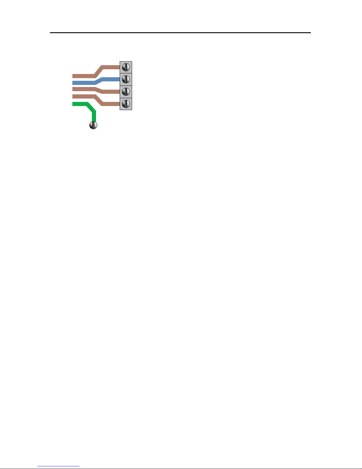
44DO NOT DIVE.
* Must be sized to swim spa specification. Swim spa rated maximum ampacity cannot exceed the
service maximum ampacity. This does not represent an option to the Installer.
NOTE: Actual wiring of RCD will vary by manufacturer of RCD. Improper wiring of RCD
may result in permanent damage to swim spa control pack. Repair / replacement of swim
spa system box is not covered under warranty when damage results from improper wiring. Actual wire attachment points on the Swim Spa Control Pack may vary. Always refer
to the wiring diagram inside the Swim Spa Control Pack for proper power connection.
ELECTRICAL REQUIREMENTS
MS40E/MS81SPAE Hook-Up
Brown L1
Blue N
Brown L2
Brown L3
Ground
1
2
3
4

45DO NOT DIVE.
As Manufactured: Single Service, TN and TT Electrical Systems (1x16 Amp or 1x32 Amp)* 3 Wires
(1 Line + 1 Neutral + 1 Protective Earth). Protective Earth wire (Green/Yellow) must be connected
to system ground terminal as marked. All equipment (pumps, heater, etc.) runs on service line L1.
Heat Disable dip switches must be evaluated to prevent the swim spa maximum ampacity from
exceeding the service maximum ampacity. Dip switch settings should not be changed from factory
settings in this configuration.
This option is configured and shipped as the default.
230V 2 phase / 2x16A:
* Must be sized to swim spa specification. Swim spa rated maximum ampacity cannot exceed the
service maximum ampacity. This does not represent an option to the Installer.
NOTE: Actual wiring of RCD will vary by manufacturer of RCD. Improper wiring of RCD
may result in permanent damage to swim spa control pack. Repair / replacement of swim
spa system box is not covered under warranty when damage results from improper wiring. Actual wire attachment points on the Swim Spa Control Pack may vary. Always refer
to the wiring diagram inside the Swim Spa Control Pack for proper power connection.
Figure 6
Blue N
Brown L1
Ground
230V 3 phase / 3x16A:
3
ELECTRICAL REQUIREMENTS
MS50E Hook-Up
1
2
3
4

46DO NOT DIVE.
As Manufactured: Single Service, TN and TT Electrical Systems (1x16 Amp or 1x32 Amp)* 3 Wires
(1 Line + 1 Neutral + 1 Protective Earth). Protective Earth wire (Green/Yellow) must be connected
to system ground terminal as marked. All equipment (pumps, heater, etc.) runs on service line L1.
Heat Disable dip switches must be evaluated to prevent the swim spa maximum ampacity from
exceeding the service maximum ampacity. Dip switch settings should not be changed from
factory settings in this configuration.
This option is configured and shipped as the default.
Optional 1: Dual Service, TN and TT Electrical Systems (2x16 Amp). 5 Wires (2 Lines + 2 Neutrals
+ 1 Protective Earth)*. Protective Earth wire (Green/Yellow) must be connected to system ground
terminal as marked. The heater runs on service line L1. All equipment (pumps, etc.) runs on service
line L2.
IMPORTANT: Each service MUST include a neutral wire, with a line to neutral voltage of 230VAC.
From the original factory configuration, remove the black wires from Section 1, J51 & J52 to
Section 3, J88 & J62. Move the white wires in Section 2, at J72, J47, & J61 and reconnect them in
Section 4, at J75, J77, & J54. Heat Disable dip switches must be evaluated to prevent the swim spa
maximum ampacity from exceeding the service maximum ampacity (L1, L2).
Figure 2
Brown L2
Blue N
Brown L1
Blue N
Ground
Figure 1
Brown L1
Blue N
Ground
ELECTRICAL REQUIREMENTS
MS6013XE Hook-Up
1
2
3
4
1
2
3
4

47DO NOT DIVE.
Optional 2: 3-Phase Service, TN and TT Electrical Systems 5 Wires (3 Lines + 1 Neutral + 1
Protective Earth)*. Protective Earth wire (Green/Yellow) must be connected to system ground
terminal as marked.
IMPORTANT: Each service MUST include a neutral wire, with a line to neutral voltage
of 230VAC.
* Must be sized to swim spa specification. Swim spa rated maximum ampacity cannot exceed the
service maximum ampacity. This does not represent an option to the Installer.
NOTE: Actual wiring of RCD will vary by manufacturer of RCD. Improper wiring of RCD
may result in permanent damage to swim spa control pack. Repair / replacement of swim
spa system box is not covered under warranty when damage results from improper wiring. Actual wire attachment points on the Swim Spa Control Pack may vary. Always refer
to the wiring diagram inside the Swim Spa Control Pack for proper power connection.
The heater runs on service line L1. All main-board equipment runs on service line L3.
Additional equipment, such as expansion boards, run on service line L2.
Completely remove the black wires from Section 1, J51 & J52 to Section 3, J88 & J62. If an expansion board is installed, black wire must connect J53 and white to J1. Move black wires from section
3 at J12 & J36 to section 4 at J45 & J79. Heat Disable dip switches must be evaluated to prevent
the spa maximum ampacity from exceeding the service maximum ampacity (L1, L2, L3).
ELECTRICAL REQUIREMENTS
MS6013XE Hook-Up
Brown L1
Blue N
Brown L2
Brown L3
Ground
1
2
3
4

48DO NOT DIVE.
MODEL SPECIFICATIONS
Model Listing
Number
Swim Spa
Dimensions
(in./cm)
1
Electrical
Requirements
4
Seating
Capacity
Water
Capacity
(gallons/m
3
)
2
Dry
Weight
(lbs./kilos)
2 & 3
Full
Weight
(lbs./kilos)
Therapy
Pumps
Control System
INT MP FORCE 8600 201"x 94"x 51"
511 x 239 x 130
*Spa Pack - 240V, 32A
Propulsion - 240V, 16A
4 1660 / 6.28 2490 /
1129
17075 /
7745
2 MS81SPAE
INT MP FORCE
WITH WAVE XP
8600 201"x 94"x 51"
511 x 239 x 130
*Spa Pack - 240V, 32A
Propulsion - 240V, 32A
4 1660 / 6.28 2490 /
1129
17075 /
7745
2 MS81SPAE
INT MP FORCE D 1420 201"x 94"x 60"
511 x 239 x 153
*Spa Pack - 240V, 32A
Propulsion - 240V, 16A
4 1935 / 7.32 2685 /
1218
19565 /
8875
2 MS81SPAE
INT MP FORCE D
WITH WAVE XP
1420 201"x 94"x 60"
511 x 239 x 153
*Spa Pack - 240V, 32A
Propulsion - 240V, 32A
4 1935 / 7.32 2685 /
1218
19565 /
8875
2 MS81SPAE
INT MP SIGNATURE
WITH WAVE XP
8900 215"x 94"x 60"
547 x 239 x 153
*Spa Pack - 240V, 32A
Propulsion - 240V, 32A
4 2275 / 8.61 2795 /
1268
22510 /
10210
2 MS81SPAE
INT MP MOMENTUM 80 8700A
- Spa
8700B - Swim
231"x 94"x 51"
587 x 239 x 130
*Spa Pack - 240V, 32A
*Swim Pack - 240V, 16A
Propulsion - 240V, 16A
6
4 - Spa
2 - Swim
2,055 / 7.78
1785 / 6.76 - Swim
270 / 1.02 - Spa"
3280 /
1488
21530 /
9766
3 Spa - MS81SPAE
Swim - MS6013XE
INT MP MOMENTUM 80
WITH WAVE XP"
8700A
- Spa
8700B - Swim
231"x 94"x 51"
587 x 239 x 130
*Spa Pack - 240V, 32A
*Swim Pack - 240V, 16A
Propulsion - 240V, 32A
6
4 - Spa
2 - Swim
2,055 / 7.78
1785 / 6.76 - Swim
270 / 1.02 - Spa
3280 /
1488
21530 /
9766
3 Spa - MS81SPAE
Swim - MS6013XE
INT MP MOMENTUM
80 D
1250A
- Spa
1250B - Swim
231"x 94"x 60"
587 x 239 x 152
*Spa Pack - 240V, 32A
*Swim Pack - 240V, 16A
Propulsion - 240V, 16A
6
4 - Spa
2 - Swim
2,325 / 8.80
2,050 / 7.76 - Swim
275 / 1.04 - Spa
3700 /
1678
24205 /
10979
3 Spa - MS81SPAE
Swim - MS6013XE
INT MP MOMENTUM
80 D WITH WAVE XP
1250A
- Spa
1250B - Swim
231"x 94"x 60"
587 x 239 x 152
*Spa Pack - 240V, 32A
*Swim Pack - 240V, 16A
Propulsion - 240V, 32A
6
4 - Spa
2 - Swim
2,325 / 8.80
2,050 / 7.76 - Swim
275 / 1.04 - Spa
3700 /
1678
24205 /
10979
3 Spa - MS81SPAE
Swim - MS6013XE
1
See Electrical Requirements section for further details.
2
Manufacturing tolerances along with other factors can result in variance in actual swim spa weight. If weight is a critical figure necessary for delivery, or final installation, we
suggest a minimum of 15% be added to the listed weight when planning delivery or installation.
3
Full weight based on dry weight of swim spa, max seating capacity of swim spa, assumed average weight per person of 185 pounds and estimated water weight of 8.34
pounds per gallon. Rounded up in increments of 5.
4
Total bather capacity in swim spa. The number of bathers in swim spa should never exceed indicated seating capacity. Depending on swim spa size, water level and bather dis-
placement; full seating capacity may not be achievable. Do not allow additional bathers to enter if bather displacment results in water levels overflowing or reaching the swim
spa controls (air controls, diverters, swim spa topside control and etc.) as this will result in water leaking out of the swim spa shell and potentially in to the equipment area.
* Default Minimum Electrical Requirement as Configured from Manufacturing. See Electrical Requirements Section for Electrical Hook-Up by Control System.

49DO NOT DIVE.
SWIM SPA STATUS
Important information about swim spa operation
can be seen quickly from the Main Screen.
The most important features, including Set
Temperature adjustment, can be accessed from this
screen.
The actual water temperature can be seen in large
text and the desired, or Set Temperature, can be
selected and adjusted.
Time-of-day, Ozone operation and Filter Operation status is available, along with other messages
and alerts.
High Temperature Range vs. Low Temperature Range is indicated in the upper right corner.
The Jets Icon in the center will indicate when a pump is running and also the heater function.
A Lock icon is visible if the panel or settings are locked.
The Menu choices on the right can be selected and the screen will change to show more detailed
controls or programming functions.
Water
Temperature
Messages
Desired
Temperature
Temperature
Range
Pump
and Heat
Menus
Lock
Indicator
Status
Set: 104°F
8:32 PM
Ozone
Filter 1
Spa
Settings
High Range
102°F
Ready in Rest Mode
Heating
Scenes
Swim spa Controls
THE MAIN SCREEN

50DO NOT DIVE.
NAVIGATION
Navigating the entire menu structure is done by touching the display on areas that are highlighted
white.
When a text item changes to white during navigation, that indicates the item is selected for action.
The only item that can be changed on the left side of the Main Screen is the Set Temperature.
Touch the temperature display to change the Set Temperature. The Set Temperature can then be
adjusted with the up and down buttons. The new setting will automatically be saved when you
exit the screen.
On the right side of the screen, the menu selections can be selected by touching the screen in any
area of white text. Selecting one of these items will change to a different screen with additional
controls.
MESSAGES
At the bottom of the screen, messages may appear at various times. Some of these messages must
be dismissed by the user
PRESS-AND-HOLD
If an Up or Down button is pressed and held when the Set Temperature is selected, the temperature will continue to change until the button is released, or the Temperature Range limits are
reached.
Set: 104°F
8:32 PM
Ozone
Filter 1
Spa
Settings
High Range
102°F
Ready in Rest Mode
Heating
Scenes
Swim spa Controls
THE MAIN SCREEN

51DO NOT DIVE.
Swim spa Controls
THE SPA SCREEN
Jets HighJets LowJets Off
ALL EQUIPMENT ACCESS
The Spa Screen shows all available equipment to control, as well as other features, in one easy-tonavigate screen. The display shows icons that are related to the equipment installed on a particular
swim spa model, so this screen may change depending on the swim spa.
Touch a button to select an individual device. The device that is chosen is highlighted with a white
outline.
Some devices, like pumps, may have more than one ON state, so the icon will change to reflect the
state that the equipment is in. Below are some examples of 2-speed Pump indicators.
If the Swim spa has a 24 hour Circ Pump, a Circ Pump Icon will appear to indicate its activity, but
outside of Priming Mode, the 24 hour Circ Pump cannot be controlled directly.
NOTE: The icon for the 24 hour pump (if so equipped) that is associated with the heater will have
a red glow in the center when the heater is running.
SCENES
The scenes area will allow you to preset any of the devices to operate when the scene is activated.
There are four different scenes that can be preset. For example if you would like all of the pumps
to turn on at the same time: turn on the pumps, access the scenes area and highlight #1. Once
this is set anytime you highlight the #1 scene all of the pumps will activate. To store a specific
scene tap and hold the highlighted scene for 5 seconds until the display shows “scene stored” in
the bottom left corner.
Ready in Rest Mode
Heating
Back Jets 1 Jets 2 Jets 3 Light

52DO NOT DIVE.
Swim spa Controls
THE SETTINGS SCREEN
TOUCHING A “BUTTON”
When instructions are given to “touch a button” any of the following can be done:
• Navigate to the desired item on any Screen. Touch the specific setting to make a change. The
arrow keys displayed on the left side of the screen will allow you to scroll through the available
options.
PROGRAMMING, ETC.
The Settings Screen is where all programming and other swim spa behaviors are controlled.
This screen has several features that can be acted on directly. These features include Temp Range,
Heat Mode, and Invert Panel. Touch the specific setting to make the change.
All other menu items (with an arrow pointing to the right) go to another level in the menu.
TOUCH-AND-HOLD
The up and down buttons on the left side of the screen allow you to scroll through the different
setting options.
DUAL TEMPERATURE RANGES (HIGH VS. LOW)
This system incorporates two temperature range settings with independent set temperatures. The
specific range can be selected on the Settings screen and is visible on the Main Screen in the upper
right corner of the display.
These ranges can be used for various reasons, with a common use being a “ready to use” setting
vs. a “vacation” setting. Each range maintains its own set temperature as programmed by the
user. This way, when a range is chosen, the swim spa will heat to the set temperature associated
with that range.
High Range can be set between 80°F and 104°F.
Low Range can be set between 50°F and 99°F.
Freeze Protection is active in either range.
Settings
Back
Temp Range
Heat Mode
Time of Day
Filter Cycles
Light Cycle
Invert Panel
Lock
High
Ready
Normal

53DO NOT DIVE.
Swim spa Controls
THE SETTINGS SCREEN
HEAT MODE – READY VS. REST
In order for the swim spa to heat, a pump needs to circulate water through the heater.
REST Mode will only allow heating during programmed filter cycles.
Ready Mode will allow heating any time the water temperature drops below the set temperature.
READY-IN-REST MODE
READY/REST appears in the display if the swim spa is in Rest Mode and the Jets 1 Button is
touched. It is assumed that the swim spa is being used and will heat to set temperature. After 1
hour, the System will revert to Rest Mode. This mode can also be reset by entering the Settings
Menu and changing the Heat Mode.
Settings
Back
Temp Range
Heat Mode
Time of Day
Filter Cycles
Light Cycle
Invert Panel
Lock
High
Ready
Normal

54DO NOT DIVE.
Swim spa Controls
Initial Start-Up
PREPARATION AND FILLING
Fill the swim spa to its correct operating level. Be sure to open all valves and jets in the plumbing
system before filling to allow as much air as possible to escape from the plumbing and the control
system during the filling process.
PRIMING MODE
After the initial start-up sequence, the control will enter
Priming Mode and display a Priming Mode screen. Only
pump icons appear on the priming mode screen. The system will automatically begin normal heating and filtering
at the end of the priming mode, which lasts 4-5 minutes.
During the priming mode, the heater is disabled to allow
the priming process to be completed without the possibility of energizing the heater under low-flow or no-flow
conditions. Nothing comes on automatically, but the
pump(s) can be activated by touching the “Jet” buttons.
Manually exit Priming Mode by touching the “Back” Button.
PRIMING THE PUMPS
As soon as the Priming Mode screen appears on the panel, touch the “Jets 1” button once to
start Pump 1 in low-speed and then again to switch to high-speed. Also, touch the other pumps,
to turn them on. The pumps should be running in high-speed to facilitate priming. If the pumps
have not primed after 2 minutes, and water is not flowing from the jets in the swim spa, do not
allow the pumps to continue to run. Turn off the pumps and repeat the process. Note: Turning the
power off and back on again will initiate a new pump priming session. Sometimes momentarily
turning the pump off and on will help it to prime. Do not do this more than 5 times. If the pump(s)
will not prime, the pump(s) will need relieved of an air lock. See Installation Instructions for information on bleeding air from a pump to relieve an air lock. If you need further assistance, your
swim spa dealer can be contacted. Regular maintenance procedures would not be covered under
the swim spa warranty.
Important: A pump should not be allowed to run without priming for more than 2 minutes. Under
NO circumstances should a pump be allowed to run without priming beyond the end of the 4-5
minute priming mode. Doing so may cause damage to the pump and cause the system to energize
the heater and go into an overheat condition.
EXITING PRIMING MODE
You can manually exit Priming Mode by touching the “Back” button on the Priming Mode Screen.
Note that if you do not manually exit the priming mode as described above, the priming mode will
be automatically terminated after 4-5 minutes. Be sure that the pump(s) have been primed by this
time.
Once the system has exited Priming Mode, the top-side panel will display the Main Screen, but the
display will not show the temperature yet, as shown below. This is because the system requires
approximately 1 minute of water flowing through the heater to determine the water temperature
and display it.
Priming Mode
Jets 1 Jets 2
CircBack Jets 3
– – –°F– – –°C

55DO NOT DIVE.
Swim spa Controls
Swim spa BEHAVIOR
PUMPS
On the Spa Screen, select a “Jets” button once to turn the pump on or off, and to shift between
low and high speeds (if equipped). If left running, the pump will turn off after a time-out period.
FILTRATION AND OZONE
The system is factory-programmed with one filter cycle that will run in the evening (assuming the
time-of-day is properly set) when energy rates are often lower. The filter time and duration are
programmable. A second filter cycle can be enabled as needed.
At the start of each filter cycle, the pumps will run briefly to purge the plumbing to maintain good
water quality.
FREEZE PROTECTION
If the temperature sensors within the heater detect a low enough temperature, then the pumps
automatically activate to provide freeze protection. The pumps will run either continuously or periodically depending on conditions. If the temperature sensors detect a drop to below 44°F/6.7°C
within the heater, the pump will automatically activate to provide freeze protection. The equipment stays on until 4 minutes after the sensors detect that the swim spa temperature has risen to
45°F/7.2°C or higher.
CLEAN-UP CYCLE (OPTIONAL)
When a pump is turned on by a button touch, a clean-up cycle begins 30 minutes after the pump
is turned off or times out. The pump and the ozone generator will run for 30 minutes or more,
depending on the system.

56DO NOT DIVE.
Swim spa Controls
TIME-OF-DAY
BE SURE TO SET THE TIME-OF-DAY
Setting the time-of-day is important for determining filtration times and other background features.
“Set Time” will appear on the display if no time-of-day is set in the memory.
On the Settings Screen, select the Time-of-Day line. On the Time-of-Day screen, simply touch
the time to select the Hour, Minutes, AM/PM and 12/24 Hour segments. Use the Up and Down
Buttons to make changes.
SAVING SETTINGS
The Time-of-Day screen is a simple, editable screen that illustrates a feature of the control that
applies to all other editable screens as well.
When changes are made, touch the back button to save the setting or touch the cancel icon to
exit without saving changes.
NOTE:
If power is interrupted to the system, Time-of-Day will be maintained for several days.
Time of Day
Back
12 :00 PM 12 HR
Time of Day
Back
12 :00 PM 12 HR
Cancel
Save
10:05 PM 12 HR

57DO NOT DIVE.
Swim spa Controls
adjusting filtration
MAIN FILTRATION
Using the same navigation and adjustment as Setting the Time, Filter Cycles are set using a start
time and a duration. Each setting can be adjusted in 15-minute increments. The panel calculates
the end time and displays it automatically.
FILTER CYCLE 2 - OPTIONAL FILTRATION
Filter Cycle 2 is OFF by default.
Simply touch the Filter Cycle 2 line in the highlighted area, and when “NO” is highlighted, press
Up or Down to toggle Filter Cycle 2 on and off. When Filter Cycle 2 is ON, it can be adjusted in the
same manner as Filter Cycle 1.
It is possible to overlap Filter Cycle 1 and Filter Cycle 2, which will shorten overall filtration by the
overlap amount.
PURGE CYCLES
In order to maintain sanitary conditions, as well as protect against freezing, the system will purge
water from the respective plumbing by running briefly at the beginning of each filter cycle.
If the Filter Cycle 1 duration is set for 24 hours, enabling Filter Cycle 2 will initiate a purge when
Filter Cycle 2 is programmed to begin.
Filter Cycles
Back
Filter Cycle 1
Starts at 12:00 AM
Runs 0 HR 0 Min
Ends at 12:00 AM
Filter Cycle 2 NO
Starts at 12:00 AM
Runs 0 HR 0 Min
Ends at 12:00 AM
Filter Cycles
Back
Filter Cycle 1
Starts at 6:15 AM
Runs 3 HR 0 Min
Ends at 9:15 AM
Filter Cycle 2 NO
Starts at 12:00 AM
Runs 0 HR 0 Min
Ends at 12:00 AM

58DO NOT DIVE.
Swim spa Controls
restricting operation
Lock
Back
Settings
Panel
OFF
ON
Set: 104°F
8:32 PM
Ozone
Filter 1
Unlock
High Range
102°F
Ready in Rest Mode
Heating
The control can be restricted to prevent unwanted use or temperature adjustments.
Locking the Panel prevents the controller from being used, but all automatic functions are still
active.
Locking the Settings allows Jets and other features to be used, but the Set Temperature and other
programmed settings cannot be adjusted.
Settings Lock allows access to a reduced selection of menu items. These include Set Temperature,
Invert, Lock, Utilities, Information and Fault Log. They can be seen, but not changed or edited.
Unlocking
When the system is locked an icon will appear in the lower right hand corner of the display.
To unlock, touch the “Unlock” text on the main screen. You can then touch the “Settings” or
“Panel” text to highlight the text. Next touch the display screen in the center and hold it for 5
seconds. The text will show that the unlocking has been completed. Touch the back button to exit
and save.
Lock
Back
Settings
Panel
OFF
OFF

59DO NOT DIVE.
Swim spa Controls
additional settings
Fault Log
Back
Entry 2
Message Code M026
1 Days Ago 2:21PM
Rest Mode
High Range
Set Temp 104°F
Sensors: A: 100 B: 96
Message:
Sensors are out of sync
HOLD MODE
Hold Mode is used to disable the pumps during service functions like cleaning or replacing the
filter. Hold Mode will last for 1 hour unless the mode is exited manually. If swim spa service will
require more than an hour, it may be best to simply shut down power to the swim spa.
UTILITIES
The Utilities Menu contains the following:
A/B Temps
When this is set to On, the A/B temperature will display in the top right corner indicating the
temperature of the sensors mounted in the heater.
Fault Log
The Fault Log is a record of the last 24 faults that can be reviewed by a service tech.
GFCI Test
When this feature is activated the control system will simulate a ground fault problem and trip
the main GFCI circuit breaker that provides power to the swim spa and the system will shut down
completely. You must then reset the main GFCI breaker for the system to begin operating again.
60DO NOT DIVE.
Swim spa Controls
additional settings
Preferences
Back
Temp Display
Time Display
Reminders
Cleanup
Dolphin
Color
Language
°F
12 HR
On
0.5 HR
5
Blue
English
PREFERENCES
The Preferences Menu allows the user to change certain parameters based on personal preference.
Temp Display
Change the temperature between Fahrenheit and Celsius.
Time Display
Change the clock between 12 hr and 24 hr display.
Reminders
Turn the reminder messages (like “Clean Filter”) On or Off.
Cleanup
Cleanup Cycle Duration default is 30 minutes. The duration can be set in 30 minute increments
for up to 4 hours. 30 minutes after any of the jet pumps have been activated, the #1 jet pump will
run low speed for the set cleanup cycle duration. If the #1 jet pump does not have low speed, this
may not apply.
Dolphin
The Dolphin control is not available on this control system.
Color
Pressing the Select Button when Color is highlighted will cycle through 5 background colors available in the control.
Language
Change the language displayed on the panel.

61DO NOT DIVE.
Swim spa Controls
INFORMATION
System Information
Back
Software ID (SSID)
System Model
Current Setup
Configuration Signature
Heater Voltage
Heater Type
Software ID (SSID):
M100_101 V0.6
SYSTEM INFORMATION
The System Information Menu displays various settings and identification of the particular system.
As each item in the menu is highlighted, the detail for that item is displayed at the bottom of the
screen. These settings are for information only and cannot be changed.
Software ID (SSID)
Displays the software ID number for the System.
System Model
Displays the Model Number of the System.
Current Setup
Displays the currently selected Configuration Setup Number.
Configuration Signature
Displays the checksum for the system configuration file.
Heater Voltage (Feature not used on CE rated systems.)
Displays the operating voltage configured for the heater.
Heater Wattage as Configured in Software (CE Systems Only.)
Displays a heater kilowatt rating as programmed into the control system software (1-3 or 3-6).
Heater Type
Displays a heater type ID number.
Dip Switch Settings
Displays a number that represents the DIP switch positions of S1 on the main circuit board.
Panel Version
Displays a number of the software in the topside control panel.

62DO NOT DIVE.
Swim spa Controls
GENERAL MESSAGES
Most messages and alerts will appear at the bottom of the normally used screens.
Several alerts and messages may be displayed in a sequence.
Some messages can be reset from the panel. Messages that can be reset will appear with a “right
arrow” at the end of the message. This message can be selected by touching the screen at the
text.
WATER TEMPERATURE IS UNKNOWN
After the pump has been running for 1 minute, the temperature will be displayed.
POSSIBLE FREEZING CONDITION
A potential freeze condition has been detected. All pumps are activated.
In some cases, pumps may turn on and off and the heater may operate during Freeze Protection.
This is an operational message, not an error indication.
THE WATER IS TOO HOT
The system has detected a swim spa water temp of 110°F (43.3°C) or more, and swim spa functions are disabled. System will auto reset when the swim spa water temp is below 108°F (42.2°C).
Check for extended pump operation, high ambient temperature, or prolonged filter cycles.
– – –°F– – –°C

63DO NOT DIVE.
Swim spa Controls
HEATER-RELATED MESSAGES
THE WATER FLOW IS LOW
There may not be enough water flow through the heater to carry the heat away from the heating
element. Heater start up will begin again after about 1 min. See “Flow Related Checks” below.
THE WATER FLOW HAS FAILED*
There is not enough water flow through the heater to carry the heat away from the heating element and the heater has been disabled. See “Flow Related Checks” below. After the problem has
been resolved, you must press any button to reset and begin heater start up.
THE HEATER MAY BE DRY*
Possible dry heater, or not enough water in the heater to start it. The swim spa is shut down for
15 min. Press any button to reset the heater start-up. See “Flow Related Checks” below.
THE HEATER IS DRY*
There is not enough water in the heater to start it. The swim spa is shut down. After the problem has been resolved, you must clear the message to restart heater start up. See “Flow Related
Checks” below.
THE HEATER IS TOO HOT*
One of the water temp sensors has detected 118°f (47.8°C) in the heater and the swim spa is
shut down. You must clear the message when water is below 108°f (42.2°C). See “Flow Related
Checks” below.
FLOW-RELATED CHECKS
Check filters for possible blockage. Try cleaning or replacing filters (especially if swim spa is
equipped with 24 hour circulation pump).
Check for low water level, clogged filters, suction flow restrictions, closed valves, trapped air, too
many closed jets and pump prime.
On some systems, even when swim spa is shut down by an error condition, some equipment may
occasionally turn on to continue monitoring temperature or if freeze protection is needed.
* This message can be reset from the topside panel.

64DO NOT DIVE.
Swim spa Controls
SENSOR-RELATED MESSAGES
SENSORS ARE OUT OF SYNC
The temperature sensors MAY be out of sync by 2°F or 3°F. Call for Service.
SENSORS ARE OUT OF SYNC -- CALL FOR SERVICE*
The temperature sensors ARE out of sync. The fault above has been established for at least 1 hour.
Call for Service.
SENSOR A FAULT, SENOR B FAULT
A temperature sensor or sensor circuit has failed. Call for Service.
COMMUNICATIONS ERROR
The control panel is not receiving communication from the System. Call for Service.
TEST SOFTWARE INSTALLED
The Control System is operating with test software. Call for Service.
°F OR °C IS REPLACED BY °T
The Control System is in Test Mode. Call for Service.
Miscellaneous Messages
* This message can be reset from the topside panel.

65DO NOT DIVE.
Swim spa Controls
SYSTEM-RELATED MESSAGES
PROGRAM MEMORY FAILURE*
At Power-Up, the system has failed the Program Checksum Test. This indicates a problem with the
firmware (operation program) and requires a service call.
THE SETTINGS HAVE BEEN RESET (PERSISTENT MEMORY ERROR)*
Contact your dealer or service organization if this message appears on more than one power-up.
THE CLOCK HAS FAILED*
Contact your dealer or service organization.
CONFIGURATION ERROR (SWIM SPA WILL NOT START UP)
Contact your dealer or service organization.
A PUMP MAY BE STUCK ON
Water may be overheated. POWER DOWN THE SWIM SPA. DO NOT ENTER THE WATER. Contact
your dealer or service organization.
HOT FAULT
A Pump Appears to have been Stuck ON when swim spa was last powered
POWER DOWN THE SWIM SPA. DO NOT ENTER THE WATER. Contact your dealer or service orga-
nization.
* This message can be reset from the topside panel.

66DO NOT DIVE.
Propulsion System Controls
THE PROPULSION SYSTEM
The unique belt-driven propulsion system provides the most consistent flow of water to swim and
exercise against. This propulsion system is controlled by the revolutionary Swim Number(TM)
System. Along with this, your MP Swim Spa is equipped with a WiFi module which allows control of the system through our *Swim Number App (SNAPP). *SNAPP is available for iPad on the
Apple store and allows you to build your own personal workouts.
The easy to operate propulsion control panel allows you not only to control the speed of the
water flow but also to select programmed Smart Workouts.
*See Swim Number App (SNAPP) Instruction Manual for further information.
OPTIONAL EXERCISE EQUIPMENT ALL
The optional exercise equipment package makes it easy to exercise in your own back yard. There
are shell mounted clips that are used to fasten the rowing equipment to the swim spa. These clips
are located along the sides of your swim spa next to the grab rails that are placed around the
perimeter of the swim area. Also available are ankle fins and exercise bells that will allow you to
do resistance training. See your Master Spas dealer for details.
NOTE: DO NOT LEAVE EXERCISE EQUIPMENT INSIDE THE SWIM SPA WHEN NOT IN USE. DO NOT
LEAVE EXERCISE EQUIPMENT OUTSIDE EXPOSED TO ULTRA VIOLET RAYS. FAILURE TO FOLLOW THE
ABOVE GUIDELINES COULD RESULT IN INJURY.

67DO NOT DIVE.
Propulsion System Controls
SWIM CONTROL OPERATION
7
4
12
13
1
2
6
14
11
8
9
3
5
10
1. Up button increases the swim number (speed).
2.
Down
button lowers the swim number (speed).
3. Swim Number indicates the speed of the propulsion drive. Speed is indicated in numbers from
1 to 100.
4. Mode reference used during workouts to calculate calorie counts when used with SNAPP APP.
During manual operation this setting can be changed by touching the highlighted text but you
will not see a change in the swim current.
5. Start button starts the propulsion drive after a 5 second delay. This delay allows the swimmer
time to get into position and prepare for the swim current.
6. Pause button allows you to momentarily pause the operation of the propulsion drive. Whenever
the drive is restarted there will be a 5 second delay before it resumes operation.
7. User workout selection allows you to choose between the default user and any custom users that
have been added through the SNAPP APP.
8. Smart Workouts
can be selected from here by touching the highlighted area. Please refer to the
Smart Workout Reference guide included with the swim spa information materials. From there
you can select Smart Workouts that will allow you exercise with preprogrammed workouts that
control the Wave Propulsion Systems.
9. Duration shows the duration of the complete workout.
10.
Elapsed Time
will be displayed in a manual mode workout and indicates the total time that the
propulsion drive has been running in the current workout and is only active in manual mode.
Remaining Time will be displayed in a Smart Workout and indicates how much time is left to
complete the workout.
11.
Step in Cycle
indicates the time you have been in a specific workout step.
12. Temperature of water in swim spa
13.
Time
of day.
14. Lock APP allows you to restrict control of the propulsion system from the Swim Number App
(SNAPP)
Note: If the topside control touch screen becomes erratic or will not function correctly, it may need to
be synced to the main control pack. To sync the topside control hold the pause button until the display
resets and displays (Synchronizing) in the lower left hand corner of the display.
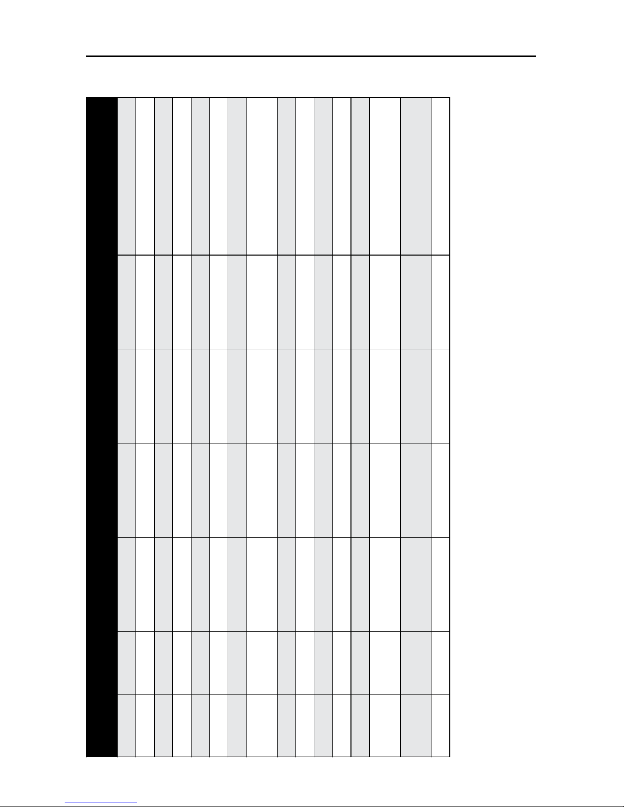
68DO NOT DIVE.
Propulsion System Controls
Beginner Fitness Workout - 9 min. 30 sec.
Step Mode Seconds * Wave Swim
Number
* Wave XP Swim
Number
* Wave XP Pro
Swim Number
**Recommended Exercise
1 Jog 15 1 1 1 Walking Forward
2 Jog 15 1 1 1 Walking Backward
3 Jog 15 1 1 1 Walking Sideways
4 Jog 15 1 1 1 Marching
5 Jog 15 1 1 1 Heel to Butt
6 Jog 15 1 1 1 Straight Leg Rise
7 Jog 15 1 1 1 Switch Legs
8 Jog 30 1 1 1 Trailing Forward/Back (Both Flow
Directions)
9 Jog 45 1 1 1 Flies
10 Jog 45 1 1 1 Push/Pulls
11 Jog 45 1 1 1 Push Downs
12 Jog 45 1 1 1 Hip Flexion/Extension
13 Jog 45 1 1 1 Hip Abduction/Adduction
14 Jog 45 1 1 1 Core rotations. 2 hand start with
isometic hold
15 Jog 45 1 1 1 Continue core rotations with Forward/
Side Flow
16 Jog 120 32 12 11 Gentle jog into flow
*Swim Number speed depends on propulsion system equipped in swim spa.
**See Swim Number App for iPad or exercise book for detailed exercise instructions.

69DO NOT DIVE.
Propulsion System Controls
Intermediate Fitness Workout - 15 min. 15 sec.
Step Mode Seconds * Wave Swim
Number
* Wave XP Swim
Number
* Wave XP Pro
Swim Number
**Recommended Exercise
1 Jog 25 1 1 1 Walking forward
2 Jog 25 1 1 1 Walking backward
3 Jog 25 1 1 1 Walking sideways (with both arms back)
4 Jog 25 1 1 1 Marching
5 Jog 25 1 1 1 Heel to butt with UE
6 Jog 25 1 1 1 Straight leg rise
7 Jog 25 1 1 1 Switch legs
8 Jog 25 1 1 1 Straight leg rise out
9 Jog 25 1 1 1 Switch legs
10 Jog 45 1 1 1 Flies forward
11 Jog 45 1 1 1 Switch legs
12 Jog 45 1 1 1 Flies side
13 Jog 45 1 1 1 Switch legs
14 Jog 45 1 1 1 Push/Pulls
15 Jog 45 1 1 1 Switch legs
16 Jog 45 1 1 1 Push downs
17 Jog 45 1 1 1 Switch legs
18 Jog 45 1 1 1 Power swings
19 Jog 45 1 1 1 Switch legs
20 Jog 45 1 1 1 Soccer kicks
21 Jog 45 1 1 1 Switch legs
22 Swim 30 76 56 48 Pikes in to flow
23 Jog 120 43 23 20 Running forward (no bells or fins)
*Swim Number speed depends on propulsion system equipped in swim spa.
**See Swim Number App for iPad or exercise book for detailed exercise instructions.

70DO NOT DIVE.
Propulsion System Controls
Advanced Fitness Workout - 27 min.
Step Mode Seconds * Wave Swim Number * Wave XP Swim Number * Wave XP Pro Swim Number **Recommended Exercise
1 Jog 45 1 1 1 Walking forward
2 Jog 45 1 1 1 Walking forward
3 Jog 45 1 1 1 Walking sideways (one arm forward,
one arm back)
4 Jog 45 1 1 1 Marching
5 Jog 45 1 1 1 Heel to butt with UE
6 Jog 45 1 1 1 Straight leg rise
7 Jog 45 1 1 1 Switch legs
8 Jog 45 1 1 1 Straight leg rise out
9 Jog 45 1 1 1 Switch legs
10 Jog 45 1 1 1 Straight leg rise in
11 Jog 45 1 1 1 Switch legs
12 Jog 75 1 1 1 Flies forward
13 Jog 75 1 1 1 Switch legs
14 Jog 75 1 1 1 Flies side
15 Jog 75 1 1 1 Switch legs
16 Jog 75 1 1 1 Alternating push/pulls
17 Jog 75 1 1 1 Switch legs
18 Jog 75 1 1 1 Alternating push downs
19 Jog 75 1 1 1 Switch legs
20 Jog 75 1 1 1 Power swings
21 Jog 75 1 1 1 Switch legs
22 Jog 75 1 1 1 Soccer kicks
23 Jog 75 1 1 1 Switch legs
24 Swim 45 1 1 1 Ronde De Jambre
25 Jog 60 65 45 39 Sprinting forward
26 Jog 60 65 45 39 Sprinting sideways
27 Jog 60 65 45 39 Sprinting backwards
*Swim Number speed depends on propulsion system equipped in swim spa.
**See Swim Number App for iPad or exercise book for detailed exercise instructions.

71DO NOT DIVE.
Propulsion System Controls
Beginner Training Workout - 15 min.
Step Mode Seconds * Wave Swim
Number
* Wave XP Swim
Number
* Wave XP Pro
Swim Number
**Recommended Exercise
1 Swim 60 54 34 30 Breast stroke
2 Jog 60 54 34 30 Running in place
3 Jog 30 1 1 1 Step-up right leg
4 Jog 30 1 1 1 Step-up left leg
5 Jog 60 65 45 39 Butt kicks
6 Jog 30 1 1 1 Arm circles forward
7 Jog 30 1 1 1 Arm circles backward
8 Jog 60 65 45 39 High knees
9 Jog 60 1 1 1 Row bars
10 Jog 60 65 45 39 Running in place
11 Jog 30 1 1 1 Band (bicep curl) right arm
12 Jog 30 1 1 1 Band (bicep curl) left arm
13 Jog 60 65 45 39 Butt kicks
14 Jog 60 1 1 1 Seated pull rows
15 Jog 60 65 45 39 High knees
16 Jog 30 1 1 1 Band (tricep extension)
17 Swim 60 65 45 39 Breast stroke
18 Swim 30 76 56 48 Body weight
19 Jog 60 43 23 20 Running in place
*Swim Number speed depends on propulsion system equipped in swim spa.
**See Swim Number App for iPad or exercise book for detailed exercise instructions.

72DO NOT DIVE.
Propulsion System Controls
Intermediate Training Workout - 30 min.
Step Mode Seconds * Wave Swim Number * Wave XP Swim Number * Wave XP Pro Swim Number **Recommended Exercise
1 Swim 120 54 34 30 Breast stroke
2 Jog 120 54 34 30 Running in place
3 Jog 60 1 1 1 Step-up right leg
4 Jog 60 1 1 1 Step-up left leg
5 Jog 60 65 45 39 Butt kicks
6 Jog 60 1 1 1 Right leg raise
7 Jog 60 1 1 1 Left leg raise
8 Jog 60 1 1 1 Arm circles forward
9 Jog 60 1 1 1 Arm circles backward
10 Jog 60 65 45 39 High knees
11 Jog 60 1 1 1 Band (shoulder press)
12 Swim 60 65 45 39 Breast stroke
13 Jog 60 1 1 1 Band (chest press)
14 Swim 60 54 34 30 Free style swim
15 Jog 60 1 1 1 Band (bicep curl) right arm
16 Jog 60 1 1 1 Band (bicep curl) left arm
17 Swim 60 54 34 30 Free style swim
18 Jog 60 1 1 1 Seated pull rows
19 Jog 60 40 45 39 Running in place
20 Jog 60 1 1 1 Bumb bells push/pull
21 Jog 60 65 45 39 Breast stroke
22 Jog 60 1 1 1 Band (tricep extension)
23 Jog 60 65 45 39 Butt kicks
24 Jog 60 1 1 1 Dumb bells push and squeeze at end
25 Jog 60 65 45 39 High knees
26 Swim 60 76 56 48 Body weight
27 Jog 120 34 14 11 Running in place
*Swim Number speed depends on propulsion system equipped in swim spa.
**See Swim Number App for iPad or exercise book for detailed exercise instructions.

73DO NOT DIVE.
Propulsion System Controls
Advanced Training Workout - 45 min.
Step Mode Seconds * Wave
Swim
Number
* Wave XP
Swim
Number
* Wave
XP Pro
Swim
Number
** Recommended
Exercise
1 Swim 120 54 34 30 Breast stroke
2 Jog 120 54 34 30 Running in place
3 Jog 60 1 1 1 Step-up right leg
4 Jog 60 1 1 1 Step-up left leg
5 Jog 60 65 45 39 Butt kicks
6 Jog 60 1 1 1 Right leg raise
7 Jog 60 1 1 1 Left leg raise
8 Jog 60 1 1 1 Arm circles forward
9 Jog 60 1 1 1 Arm circles
backward
10 Jog 60 65 45 39 High knees
11 Jog 60 1 1 1 Band (shoulder
press)
12 Swim 120 65 45 39 Breast stroke
13 Jog 60 1 1 1 Band (chest press)
14 Swim 120 76 56 48 Free style swim
15 Jog 60 1 1 1 Step-up right leg
16 Jog 60 1 1 1 Step-up left leg
17 Swim 120 65 45 39 Breast stroke
18 Jog 60 1 1 1 Band (bicep curl)
right arm
Step Mode Seconds * Wave
Swim
Number
* Wave XP
Swim
Number
* Wave
XP Pro
Swim
Number
** Recommended
Exercise
19 Jog 60 1 1 1 Band (bicep curl)
left arm
20 Swim 120 76 56 48 Free style swim
21 Jog 60 1 1 1 Seated pull rows
22 Jog 60 1 1 1 Arm circles forward
23 Jog 60 1 1 1 Arm circles
backward
24 Swim 120 65 45 39 Breast stroke
25 Jog 60 1 1 1 Dumb bells push/
pull
26 Swim 120 76 56 48 Free style swim
27 Jog 60 1 1 1 Band (tricep exten-
sion)
28 Jog 60 1 1 1 Step-up right leg
29 Jog 60 1 1 1 Step-up left leg
30 Jog 60 60 45 39 Butt kicks
31 Jog 60 1 1 1 Dumb bells push
and squeeze at end
32 Jog 60 1 1 1 Arm circles forward
33 Jog 60 1 1 1 Arm circles
backward
34 Jog 60 64 45 39 High knees
35 Swim 60 76 56 48 Body weight
36 Jog 120 34 14 11 Running in place
*Swim Number speed depends on propulsion system equipped in swim spa.
**See Swim Number App for iPad or exercise book for detailed exercise instructions.

74DO NOT DIVE.
Propulsion System Controls
Beginner Swim Workout - 25 min.
Step Mode Seconds * Wave Swim Number * Wave XP Swim Number * Wave XP Pro Swim Number **Recommended Exercise
1 Swim 60 61 41 35 Free Style Swim
2 Swim 60 61 41 35 Kick Chore
3 Swim 60 54 34 30 Catch Up Drill
4 Swim 60 67 47 40 Backstroke
5 Jog 60 1 1 1 Jog in Place
6 Swim 60 67 47 40 Free Style Swim
7 Swim 60 61 41 35 Kick Chore
8 Swim 60 54 34 30 Catch Up Drill
9 Swim 60 67 47 40 Backstroke
10 Jog 60 1 1 1 Jog in Place
11 Swim 60 67 47 40 Free Style Swim
12 Swim 60 61 41 35 Kick Chore
13 Swim 60 54 34 30 Catch Up Drill
14 Swim 60 67 47 40 Backstroke
15 Jog 60 1 1 1 Jog in Place
16 Swim 60 67 47 40 Free Style Swim
17 Swim 60 61 41 35 Kick Chore
18 Swim 60 54 34 30 Catch Up Drill
19 Swim 60 67 47 40 Backstroke
20 Jog 60 1 1 1 Jog in Place
21 Swim 60 67 47 40 Free Style Swim
22 Swim 60 61 41 35 Kick Chore
23 Swim 60 54 34 30 Catch Up Drill
24 Swim 60 67 47 40 Backstroke
25 Swim 60 61 41 35 Free Style Swim
*Swim Number speed depends on propulsion system equipped in swim spa.
**See Swim Number App for iPad or exercise book for detailed exercise instructions.

75DO NOT DIVE.
Propulsion System Controls
Intermediate Swim Workout - 25 min. 30 sec.
Step Mode Seconds * Wave Swim
Number
* Wave XP Swim
Number
* Wave XP Pro
Swim Number
**Recommended Exercise
1 Swim 120 54 34 30 Free Style Swim
2 Swim 60 54 34 30 Fly Drill 2-2-2
3 Swim 60 1 1 1 W Fly 5 Strokes Fast + 10 55 FR EZ
4 Swim 120 1 1 1 Free Style Moderate Effort
5 Swim 60 65 45 39 Free Style Hard Effort
6 Jog 30 1 1 1 Jog in Place
7 Swim 60 1 1 1 Fly Drill 2-2-2
8 Swim 60 1 1 1 W Fly 5 Strokes Fast + 10 55 FR EZ
9 Swim 120 1 1 1 Free Style Moderate Effort
10 Swim 60 65 45 39 Free Style Hard Effort
11 Jog 30 1 1 1 Jog in Place
12 Swim 60 65 45 39 Fly Drill 2-2-2
13 Swim 60 1 1 1 W Fly 5 Strokes Fast + 10 55 FR EZ
14 Swim 120 1 1 1 Free Style Moderate Effort
15 Swim 60 65 45 39 Free Style Hard Effort
16 Jog 30 1 1 1 Jog in Place
17 Swim 60 65 45 39 Fly Drill 2-2-2
18 Swim 60 1 1 1 W Fly 5 Strokes Fast + 10 55 FR EZ
19 Swim 120 65 45 39 Free Style Moderate Effort
20 Swim 60 76 56 48 Free Style Hard Effort
21 Swim 120 34 14 11 Free Style Swim
*Swim Number speed depends on propulsion system equipped in swim spa.
**See Swim Number App for iPad or exercise book for detailed exercise instructions.

76DO NOT DIVE.
Propulsion System Controls
Advanced Swim Workout - 41 min.
Step Mode Seconds * Wave
Swim
Number
* Wave XP
Swim
Number
* Wave
XP Pro
Swim
Number
** Recommended
Exercise
1 Swim 180 67 47 40 Free Style Swim
2 Swim 60 67 47 40 Catchup with
Steady Kick
3 Swim 60 80 60 50 Free Style Moderate
Effort
4 Swim 60 96 76 65 Free Style Hard
Effort
5 Swim 60 67 47 40 KKP Breast Drill
6 Swim 60 96 76 65 Breast Hard
7 Jog 60 1 1 1 Jog in Place
8 Swim 60 61 41 35 EZ Kick
9 Swim 60 67 47 40 Moderate Kick
10 Swim 60 74 54 46 Hard Kick
11 Swim 60 67 47 40 Catchup with
Steady Kick
12 Swim 60 80 60 50 Free Style Moderate
Effort
13 Swim 60 96 76 65 Free Style Hard
Effort
14 Swim 60 67 47 40 KKP Breast Drill
15 Swim 60 96 76 65 Breast Hard
16 Jog 60 1 1 1 Jog in Place
17 Swim 60 61 41 35 EZ Kick
18 Swim 60 67 47 40 Moderate Kick
19 Swim 60 74 54 46 Hard Kick
Step Mode Seconds * Wave
Swim
Number
* Wave XP
Swim
Number
* Wave
XP Pro
Swim
Number
** Recommended
Exercise
20 Swim 60 67 47 40 Catchup with
Steady Kick
21 Swim 60 80 60 50 Free Style Moderate
Effort
22 Swim 60 96 76 65 Free Style Hard
Effort
23 Swim 60 67 47 40 KKP Breast Drill
24 Swim 60 96 76 65 Breast Hard
25 Jog 60 1 1 1 Jog in Place
26 Swim 60 61 41 35 EZ Kick
27 Swim 60 67 47 40 Moderate Kick
28 Swim 60 74 54 46 Hard Kick
29 Swim 60 67 47 40 Catchup with
Steady Kick
30 Swim 60 80 60 50 Free Style Moderate
Effort
31 Swim 60 96 76 65 Free Style Hard
Effort
32 Swim 60 67 47 40 KKP Breast Drill
33 Swim 60 96 76 65 Breast Hard
34 Jog 60 1 1 1 Jog in Place
35 Swim 60 61 41 35 EZ Kick
36 Swim 60 67 47 40 Moderate Kick
37 Swim 60 74 54 46 Hard Kick
38 Swim 120 61 41 35 Free Style Swim
*Swim Number speed depends on propulsion system equipped in swim spa.
**See Swim Number App for iPad or exercise book for detailed exercise instructions.

77DO NOT DIVE.
Swim Spa Propulsion System
Technical Information
CRITICAL REPLACEMENT COMPONENT PART NUMBERS:
WARNING: Items listed below shall only be replaced with identical components unless approved
by Master Spas Engineering Department. Any change or alteration to the system components will
cause a safety hazard and void the safety certification.
PROPULSION SUCTION GRATES MISC. SPECIFICATIONS:
• Wall mount only
• Life span 7 years
• Tools required – No. 2 Phillips screwdriver
• Pulley system shall be 1:1 ratio only
Note: Fittings and fasteners should be observed for damage or tampering before each use of the
swim spa.
• Propulsion suction grate assembly: X804490
• Propulsion grate fasteners (4 per grate): X717900
• Propeller
- Wave ..................X400125
- Wave XP ............X400820
- Wave XP PRO .....X400820
• *Max. Frequency
- Wave ..................66Hz.
- Wave XP ............60Hz.
- Wave XP PRO .....68Hz.
*This is the certified maximum frequency. Actual frequency setting may vary.
Note: The propulsion system is designed to operate at any speed (Swim Number 1-100) for 30 minutes. The propulsion system can be operated for as much as 60 minutes continuous as long as the
Swim Number is limited to 90 or below. If Swim Number exceeds 90 for more than 30 minutes, the
propulsion motor could shut down to protect itself or trip the internal GFCI breaker. This is considered normal and can be avoided by operating the system as described above. If the system shuts
down, verify that the internal GFCI is reset (on), allow time for the motor to cool, then operate as
normal.

78DO NOT DIVE.
FUSION TOUCH SOUND (if equipped)
The Balboa BT Audio option offers Bluetooth connection to play audio from a mobile Bluetooth audio capable
device. The functions of the BBA system such as power, volume and skipping tracks can be performed from the
swim spa topside control panel within the Music menu.
When in the Music menu, the screen will indicate the current status of the BBA system. This screen indicates the
audio system is currently off.
Touch power icon to turn BBA audio system on/off.
Warning: Never remain in your swim spa longer than 15 minutes per session when the water temperature is
above 98˚F (36˚C). If you wish to spend more time in your swim spa, whether enjoying music, or just lounging,
be sure to keep the swim spa water at or below body temperature (98.6˚F / 37˚C).

79DO NOT DIVE.
FUSION TOUCH SOUND (if equipped)
BLUETOOTH CONNECTION:
1. Turn on the amplifier from the Music menu of swim spa control panel.
2. Turn on Bluetooth function of your mobile or music device
3. On your mobile device, click search for Bluetooth device.
Make sure you are close to the swim spa.
4. Select “PPGME60” from the pairing list.
5. Enter “6000” as the password (if required). On some older units the passcode is “60BT”
6. Click “Connect”
7. Once connected, you can now start playing your favorite music from your music device.
8. Operating Range is up to 30’ (will vary, dependent on installation)
Once powered up, system will indicate discoverable. Discoverable indicates the system is open for connection
with a mobile Bluetooth audio device. BT Connected indicates that a Bluetooth audio device is connected to
the BBA system. BT Not Connected indicates that no Bluetooth connection was made during the discoverable
time and the unit has shut off Bluetooth connection. Use power icon to cycle power off and then on to make
Bluetooth discoverable again.
Warning: Never remain in your swim spa longer than 15 minutes per session when the water temperature
is above 98˚F (36˚C). If you wish to spend more time in your swim spa, whether enjoying music, or just lounging,
be sure to keep the swim spa water at or below body temperature (98.6˚F / 37˚C).

80DO NOT DIVE.
Deluxe Fusion BT Stereo Option (if equipped)
Warning: Never remain in your swim spa longer than 15 minutes per session when the water temperature is
above 98˚F. If you wish to spend more time in your swim spa, whether enjoying music, or just lounging, be sure
to keep the swim spa water at or below body temperature (98.6˚F).
CAUTION – Risk of Electric Shock. Do not operate the audio controls while inside the swim spa.
CAUTION – Risk of Electric Shock. Do not operate, open, shut or connect devices
to dock with wet hands.
CAUTION – Risk of Electric Shock. Do not leave compartment door open.
CAUTION – Risk of Electric Shock. Replace components only with identical components.
WARNING – Prevent Electrocution. Do not connect any auxiliary/external components to the
system (i.e. cables, additional speakers, headphones, additional Audio/Video components, etc.).
NOTE: These units are not provided with an outdoor antennae; if added, it should be installed in
accordance with article 810 of the National Electrical Code, ANSI / NFPA 70.
NOTE: Do not service this product yourself as opening or removing covers may expose you
to dangerous voltage or other risk of injury. Refer all servicing to qualified service personnel.

81DO NOT DIVE.
Deluxe Fusion BT Stereo Option –
Location of Controls
1.1 DIGITAL MEDIA LOCKER CONTROLS
1. Open/Close Latch & Protective Door
2. Power ON/OFF Button
3. Water/Dust Protection Inner Gasket
4. 3.5mm Aux Input for MP3 Devices
5. Power ON/OFF LED
6. Security Strap for digital media devices
7. USB Connector
8. Door Control Keypad
9. LED Mode Indicator
10. Back lighting
11. Cable Storage Tray
2
9
11
10
6
7
3
5
4
8
1

82DO NOT DIVE.
Deluxe Fusion BT Stereo Option –
Location of Controls
Buttons Music Mode: iPhone, iPod,
Bluetooth, USB & MP3
FM Radio Mode
Power Press once: Toggle from Operation mode to Standby mode or vice-versa.
Mode
Press once: Change the source.
Press and hold: No function
Press once: Change the source.
Press and hold: No function
Volume Up
Press once: Volume up
Press and hold: Fast volume up
Press once: Volume up
Press and hold: Fast volume up
Volume Down
Press once: Volume down
Press and hold: Fast volume down
Press once: Volume down
Press and hold: Fast volume down
Fast Rewind
Press once: Previous track
Press and hold: Fast rewind
Press once: Scan down
Press and hold: Toggle manual seeking
Fast Forward
Press once: Next track
Press and hold: Fast forward
Press once: Scan up
Press and hold: Toggle to manual
seeking
12V Trigger /
Random
Press once: Random playback
Press and hold: Toggle 12V on/off
Press once: No function
Press and hold: Toggle external 12V
power on/off
Play/pause
Press once: Play/Pause
Press and hold: No function
Press once: Toggle mute
Press and hold: No function
1 / DIR-
Press once: Back to previous folder
Press and hold: No function
Press once: Listen to FM preset station
1
Press and hold: Set preset FM station 1
2 / REPEAT
Press once: Repeat function
Press and hold: No function
Press once: Listen to FM preset station
2
Press and hold: Set preset FM station 2
3 / DIR+
Press once: Forward to next folder
Press and hold: No function
Press once: Listen to FM preset station
3
Press and hold: Set preset FM station 3
The keypad on the door has a set of keys fewer than those on the remote but has exactly
the same functions correspondingly. This keypad allows you to operate the dock without the
remote control.
1.2 DOOR KEYPAD CONTROLS

83DO NOT DIVE.
Deluxe Fusion BT Stereo Option –
Location of Controls
Buttons Music Mode: iPhone, iPod,
Bluetooth, USB & MP3
FM Radio Mode
Power
Press Once: Turns remote control on.
Press Twice: Toggle from Operation mode to Standby mode or vice-versa.
Mode
Press once: Change the source.
Press and hold: No function
Press once: Change the source.
Press and hold: No function
Search/Audio
Press once: Search
Press and hold: Audio Menu (BAS-TREBAL-FAD-EUR-DXMONO-STEREO)
Press once: Audio Menu (BAS-TRE-BALFAD-EUR-DX-MONOSTEREO)
Press and hold: Audio Menu (BAS-TREBAL-FAD-EUR-DXMONO-STEREO)
Volume Up
Press once: Volume up
Press and hold: Fast volume up
Press once: Volume up
Press and hold: Fast volume up
Volume Down
Press once: Volume down
Press and hold: Fast volume down
Press once: Volume down
Press and hold: Fast volume down
Play/Pause
Press once: Play/Pause
Press and hold: No function
Press once: Toggle mute
Press and hold: No function
Fast Rewind
Press once: Previous track
Press and hold: Fast rewind
Press once: Scan down
Press and hold: Toggle manual seeking
Fast Forward
Press once: Next track
Press and hold: Fast forward
Press once: Scan up
Press and hold: Toggle manual seeking
1 / DIR-
Press once: Back to previous folder
Press and hold: No function
Press once: Listen to FM preset station 1
Press and hold: Set preset FM station 1
2 / REPEAT
Press once: Repeat playback function
Press and hold: Repeat function
Press once: Listen to FM preset station 2
Press and hold: Set preset FM station 2
3 / DIR+
Press once: Forward to next folder
Press and hold: No function
Press once: Listen to FM preset station 3
Press and hold: Set preset FM station 3
12V Trigger /
Random
Press once: Random playback function
Press and hold: Toggle external
Press once: No function
Press and hold: Toggle external 12V power
on/off
If your music player is connected via the Auxiliary input you will
not be able to control track or receive track information.
In order to prolong remote battery life the LCD will shut off in
20 seconds if no other button is pressed. To turn remote back
on press any key once and then press the command desired.
Turn off DSP to access control of Bass and Treble.
When in Bluetooth mode Repeat and Random playback func-
tions must be enabled via your media device and not from the
remote control.
1.3 REMOTE CONTROL

84DO NOT DIVE.
Deluxe Fusion BT Stereo Option –
Getting started
2.1 REMOTE CONTROL BATTERY INSTALL
Remove the RF wireless remote control from the Digital Media Locker box. Unscrew the waterproof
cap on the back of the remote control. Place the CR-2450 battery in the RF remote control and
replace the water/dust proof cap.
When the battery is installed, the remote control LCD should be solid and bright without any flickering.
2.2 POWER ON
Press the
on/off button.
Red Light: Power to the docking station is ON, but the unit is in standby mode.
Blue Light: The unit is powered ON and looking for an audio source.
For applications that require low current draw and where battery drain may occur, the power button must be turned OFF inside the unit. When the power button is in the OFF position the red LED
will not be lit.
For applications where a 12V battery is not used, such as in a swim spa, the power button can be
left ON and the remote control or door controls can then be used to power on/off accordingly.
2.3 REMOTE CONTROL SYNCHRONIZING
1. Turn the Digital Media Locker to off mode with the power button inside the door. The LED
should not be illuminated.
2. Press the red
(POWER) button on the remote.
3. Press and hold the
(MODE) button until the LCD reads PAIR.
4. Continue to press and hold the
(MODE) button during step 5 below.
5. Turn the docking station to standby mode (within 10 seconds) with the on/off button inside
door (the red LED will illuminate and then turn blue).
6. The remote’s LCD should read WELCOME or show a mode position such as RADIO, USB, BT or
AUX IN.
For any additional remote controls, you will also need to activate/synchronize those remote controls
by following the steps above.
If the pairing process is not effective, switch the locker off using the on/off button located
inside the door of the dock. Unplug the 12-pin Harness on the back of the Locker for 3 minutes. Reattach the Harness and repeat steps 1-6 above.
If the pairing process is not effective, check the battery voltage. If above 3V DC refer to section 1.5 above top make sure the battery is installed correctly. If battery voltage is below 3V
DC replace the battery.
If the LCD displays “NO LINK” in either mode, this means the remote is out of reception range.
Move the remote closer to the Locker and try again.
If you lose your remote control and buy another new remote control, please follow the above
to start pairing before normal usage.

85DO NOT DIVE.
Deluxe Fusion BT Stereo Option –
Listening to Devices
3.1 LISTENING VIA USB
1. Power up the Digital Media Locker
2. Attach your device to the USB cable inside the Digital Media Locker using the appropriate USB
adaptor.
3. Secure the device with the anchor straps provided.
4. Secure the Digital Media Locker’s protective door.
5. Press (POWER) on the remote control or Power button on the locker to turn it ON.
6. Press
(MODE) on the remote control to select USB mode. Use the buttons as shown in the
remote function chart.
Always ensure to connect and disconnect your media player with dry hands!
3.1.1.1 USB SEARCH
1. When using a USB device, press
(SEARCH) to enter the USB searching mode.
2. Use
and
(Volume UP/DOWN) to scroll through the folders on your USB device and to
select a folder press the
(PLAY/PAUSE) button.
3. Use
and
(Volume UP/DOWN) to scroll through the songs in the folder and press
(PLAY/PAUSE) to play the desired song.
3.1.1.2 IPHONE & IPOD SEARCH
1. When using an iPhone or iPod, press
(SEARCH) to enter iPod searching mode.
2. Once in searching mode the remote will display ‘Playlist’. Continue to press
(SEARCH) to
scroll through the search modes below:
1) Playlist 2) Artist 3) Album 4) Song 5) Genre 6) Composer 7) Audio Book
3. Press
(PLAY/PAUSE) To select the desired search mode.
4. Use
and
(Volume UP/DOWN) to scroll through your media in the selected search mode.
5. Once you find the desired media press
(PLAY/PAUSE) to make your selection. If your section
is a song it will begin to play, if you select a playlist, artist, album, genre, composer or audio
book, the songs in the selected folder will be visible. Press
(PLAY/PAUSE) to play the desired
song within the folder.
3.1.2 DEVICE CHARGING
When specified USB devices are connected to the USB input the device battery will charge.

86DO NOT DIVE.
Deluxe Fusion BT Stereo Option –
Listening to Devices
3.1.3 IPHONE & IPOD COMPATIBLE MODELS
3.2.1 PAIR WITH BLUETOOTH DEVICE
1. Switch on your Bluetooth device.
2. Select ‘AQUATIC AV’ from the list of available devices to pair (no password is needed).
Only one Bluetooth device can be paired with the Digital Media Locker at any time. If another
device is within range and paired, a new device will not be able to pair/connect. Disconnect
other device or reset power and immediately try pairing new device.
This audio system is compatible with many Bluetooth devices. Master Spas Inc. does not guar-
antee compatibility with all Bluetooth devices.
3.2.2 LISTENING VIA BLUETOOTH DEVICE
1. Bluetooth mode will be activated once a Bluetooth device is linked.
2. Play the song from device and the sound will play through the Digital Media Locker.
3. Press
(PLAY/PAUSE) to play/pause the song.
4. Press
/
(FAST REWIND/FORWARD) buttons to play previous/next song file.
5. Track and volume can be controlled directly from your Bluetooth device, remote control or door
controls.
3.3 LISTENING VIA AUXILIARY INPUT
1. Power up the Digital Media Locker.
2. Connect your MP3 device to either the 3.5mm Jack input or RCA input
3. Secure the device with the anchor straps provided.
4. Secure the Digital Media Locker’s protective door.
5. Press
(MODE) on the remote control to select ‘AUX IN’ mode.
Only one Auxiliary input (3.5mm Jack or RCA) can be used at any one time.
3.4 ADJUST VOLUME LEVEL
1. Press
(VOLUME UP) once to increase the volume.
2. Press
(VOLUME DOWN) once to reduce the volume.
3. Press
and
hold either or and the Digital Media Locker will increase or decrease audio
volume continuously.

87DO NOT DIVE.
Deluxe Fusion BT Stereo Option –
Listening to FM Radio
4.1 ENTER FM RADIO MODE
1. Press
(MODE) on remote control to switch to FM radio mode.
If this is the first time you listen to FM radio, the default frequency will be 87.5MHz, as shown
on the remote LCD.
FM radio is only available when you are in the FM Radio mode.
4.2 SCAN OR SEEK FM RADIO CHANNELS
1. Press
(FAST REWIND) or (FAST FORWARD) to seek another station.
2. Press and hold either
(FAST REWIND) or (FAST FORWARD) for manual tuning back or
forward.
After using Seek mode the unit will automatically switch back into Scan mode after 20 seconds.
4.3 SAVING RADIO CHANNEL TO MEMORY
To save the current frequency into memory, press and hold
, or
for more than 2 sec-
onds. The station will be stored into relevant button.
4.4 LISTENING TO SAVED RADIO MEMORY
Press the
, or
preset button once to listen to the station stored in that button.
4.5 SWITCH BETWEEN US AND EUROPEAN FM MODES
1. Make sure dock and remote are turned on and in ‘RADIO’ mode.
2. Press the AUDIO button 6 times in a row.
3. The remote will display ‘AREA USA’ or ‘AREA EUR’ depending on which tuning mode is cur-
rently selected.
4. Use the
and
buttons to switch between US or European modes.
5. Press
PLAY/PAUSE) to select the desired tuning mode.
6. Once you switch modes it will default to the FM station stored in ‘PRESET’.
US mode will increase and decrease the FM frequency in steps of 0.1 MHz, e.g. 88.5, 88.6,88.7
MHz. EUR mode will increase and decrease the FM frequency in steps of 0.05 MHz, e.g. 88.25,
88.30, 88.35 MHz.
When in Seek mode and European FM tuning mode, all frequency steps will be visible.
4.6 ADJUST VOLUME LEVEL
1. Press
(VOLUME UP) once to increase the volume.
2. Press
(VOLUME DOWN) once to reduce the volume.
3. Press and hold either
or
and the Digital Media Locker will increase or decrease audio
volume continuously.

88DO NOT DIVE.
Deluxe Fusion BT Stereo Option –
Additional Features
5.1 INTERNAL DOCK LIGHT
Use the trigger on the remote to toggle the internal illumination light ON/OFF.

89DO NOT DIVE.
WARNING:
BEFORE PERFORMING ANY MAINTENANCE ON THE MAST3RPUR SYSTEM, MAKE SURE THE SWIM
SPA IS SHUT DOWN.
a. UV Lamp Removal – See Figure 2.
If the Green Power Indicator is on, but the Blue UV Lamp Indicator is off, the UV lamp needs to
be replaced. For maximum UV sanitation effect, replace the UV Lamp every 18 months.
i. Make sure the unit is disconnected from power and the lamp has cooled before starting
maintenance.
ii. Open the Spa Solar Eclipse by removing the two Enclosure Screws on the Upper Enclosure
Assembly and lifting it from the Enclosure Base.
iii. Disconnect the Lamp Connector attached to the lamp wires and place the Upper Enclosure
Assembly in a safe place.
iv. Gently pull the Lamp Wires till the top of the UV Lamp is out of the Lamp Retainer. Grasp
the white ceramic end of the UV Lamp and pull until it is fully removed. IF YOU ARE NOT
REPLACING THE LAMP, DO NOT TOUCH THE UV LAMP GLASS WITH YOUR BARE HANDS. The
oils on your hands can cause hot spots on the lamp and shorten its life. If oil from your fingers is left on the lamp glass, clean it off with a soft towel and rubbing alcohol. If you are
removing an old lamp for replacement, handle the lamp carefully and dispose properly (see
Environmental Notice below).
v. Set the UV Lamp aside in a safe place.
Mast3rPur (if equipped)
Figure 2: Spa Solar Eclipse Exploded View
Note: This regular maintenance for the Mast3rPur system is not covered under the warranty of the
swim spa. Your Master Spas Dealer or Service Center can be contacted to schedule this maintenance.

90DO NOT DIVE.
Mast3rPur (if equipped)
b. Installing the UV Lamp
i. Make sure to handle the new lamp by the ceramic endcaps and clean the UV Lamp before
installation if needed.
ii. Slowly place the UV Lamp into the Lamp Retainer until the top of the UV Lamp is pushed
past the tabs on the Lamp Retainer.
iii. Connect the Lamp Connector to its corresponding part in the Ballast Assembly.
ENVIRONMENTAL NOTICE: UV Lamp CONTAINS MERCURY. Manage in accordance with disposal
laws. See: www.lamprecycle.org
c. UV Reactor Service and Maintenance
The UV Lamp is housed in a Quartz Tube. If the Quartz Tube becomes dirty, its ability to transmit
rays from the UV Lamp will be diminished and decrease system performance. The Quartz Tube
should be removed from the UV Reactor at least once a year or during a routine swim spa water
change for inspection and cleaning if necessary.
d. Quartz Tube Removal and Cleaning
CAUTION: Wear proper eye and skin protection for servicing glass components.
i. Make sure the swim spa is shut down and the UV Lamp and Quartz Tube have cooled
before performing maintenance on the Quartz Tube. If you have installed Isolation Valves,
close them before servicing. If you do not have Isolation Valves, the swim spa must be
drained below where the Spa Solar Eclipse is mounted.
ii. Remove the Upper Enclosure Assembly and UV Lamp as described in Section A and set aside
in a safe place.
iii. Remove the two Retainer Screws and Retainer Washer from the top of the Lamp Retainer
and slowly pull the Lamp Retainer out of the UV Chamber Cap.
CAUTION: If there is any water remaining in the plumbing, it will start to leak after the Lamp
Retainer is removed.
iv. Grasp the inside of the Quartz Tube and pull it out of the housing. Make sure the Sealing
Ring does not get lost during Quartz Tube removal.
v. Inspect the Sealing Ring for nicks or hardness and replace if necessary.
vii. Clean the Quartz Tube exterior with a mild solution of muriatic acid and water in a ratio
of four parts water to one part acid (4:1). DO NOT USE ABRASIVE CLEANERS as they can
scratch the high quality quartz glass.
CAUTION: Follow the directions for safe use and handling of muriatic acid on the acid bottle label.
Never add water to acid. Always add acid to water.
vii.
After cleaning the Quartz Tube, wash it off with water and wipe dry with a soft towel. Inspect
the Quartz Tube for cracks and replace if cracks are found.
viii. Make sure the inside of the Quartz Tube is dry before replacing the UV Lamp(s).
NOTE: Damage caused by broken quartz tubes is not covered under the Mast3rPur System Limited
Warranty.

91DO NOT DIVE.
Mast3rPur (if equipped)
e. Quartz Tube Installation
i. Place the Sealing Ring on the Quartz Tube 3/4 inch from the open end.
ii. Insert the Quartz Tube partially into the UV Chamber Cap. Place the Lamp Retainer over the
open end of the Quartz Tube and slowly push in until it is touching the UV Chamber Cap.
iii. Place the Retainer Washers onto the Retainer Screws and screw the Lamp Retainer Screws
until the Lamp Reatiner is completely seated against the UV Chamber Cap.
iv. After swim spa is refilled, turn the swim spa ON and check the seal around the Lamp
Retainer for leaks.
v. Correct any leak found by carefully tightening the retainer screws making sure lamp retainer
is snug. Be careful not to over-tighten and damage lamp retainer. If leaking continues, contact your Master Spas dealer for service.
vi. SHUT DOWN the swim spa once you have confirmed that there are no leaks.
vii. Install the UV Lamp as described in Section B.
viii. Reinstall the Upper Enclosure Assembly to the Enclosure Base.
ix. The unit is now ready for normal operation.
Contact your Master Spas dealer for replacement Mast3rPur parts and scheduling service for this
regular maintenance..
Note: The ozone hose and check valve connecting between the ozone generator and ozone injector
should be inspected and/or replaced, if necessary, every 12 months. Depending on conditions of the
air which is being brought in to the ozone generator, the ozone hose and check valve can wear more
rapidly. This regular maintenance is not covered under the swim spa warranty.

92DO NOT DIVE.
SoftTread™ Floor System by SWIMDek®
(if equipped)
The exclusive SoftTread Floor System by SwimDek is available as a premium option on swim spas
manufactured by Master Spas to provide the ultimate in traction while using your new swim spa
for any activity. Safety while using your swim spa is of the utmost importance to Master Spas and
we’ve literally got you covered with the SoftTread Floor System by SwimDek.
Applied to each entry and exit step as well as the large floor area, safety and comfort are a given.
The SoftTread Floor System by SwimDek grips each movement of your feet making exercises easier
and more comfortable with the unique combination of traction and cushion. Experience the
comfort and safety of this flooring only on swim spas manufactured by Master Spas.
Care & Maintenance Recommendations:
• SoftTread Floor System by SwimDek cleans easily with soap, hot water and a brush (soft to
medium bristle stiffness). Chlorine/bleach and water mixture, isopropyl rubbing alcohol or other
household cleaner such as SoftScrub, Simple Green and 409 can be used to clean the pads.
Be sure any soap or cleaning product is thoroughly rinsed from the pads and swim spa shell and
this residue is removed before re-filling swim spa to prevent foaming.
• Always promptly attend to and clean any noticeable stains.
Never:
• Allow stains to develop without promptly being attended to and cleaned.
• Clean with acid based cleaning products.
• Use acetone or mineral spirits on SoftTread Floor System by SwimDek or swim spa shell as dam-
age caused to the swim spa shell from these chemicals would not be warranted.
SoftTread is a registered trademark of Hyperform, Inc, dba SwimDek.


Master Spas Inc.
6927 Lincoln Parkway
Fort Wayne, IN 46804
www.MasterSpas.com
The manufacturer reserves the right to change specifications or features without
notice. As a manufacturer of swim spas and related products we stand behind every
product we produce pursuant to those representations which are stated in our written
limited warranty. Your dealer is an independent business person or company and not an
employee or agent of the manufacturer. We cannot and do not accept any responsibility or
liability for any other representations, statements or contracts made by any dealer beyond
the provisions of our written limited warranty.
POP17MPSSINTOM
Rev. 201708
 Loading...