

Page 1

Model MK-470
Tile Saw
Owner’s Manual
Parts List &
Operating
Instructions
Warning:
• For your own safety read instruction manual
before operating saw.
• Wear eye protection.
• Use splash hood for every operation for which it
can be used.
• Disconnect saw before servicing, when
changing cutting wheels, and cleaning.
• Use tool only with smooth edge cutting wheels
free of openings and grooves.
• Replace damaged cutting wheel before
operating.
R
please record the serial number (Located on the
cover post casting) of your saw in this block.
serial number
For your warranty to be effective, complete the
warranty card (include the serial number) and
mail it in as soon as possible.
Manual Part No. 156934
Revision 10/01
Page 2

Ta b l e o f C o n t e n t s
General Safety Instructions pg 1-2
Safety Messages
Hazard Symbols
Damage Prevention Messages
Safety Label Locations
Saw Features pg 2-3
Motor
Cutting Head
Water Recirculation System
Unpacking and Preparation pg 3
Initial Assembly pg 3-5
Installing the Cutting Head
Installing the Blade
Installing the Water Pump
Electrical Requirements
Lockout Method
Sawing Operations pg 5-6
General Cutting Guidelines
Table Markings
Maintenance pg 6
Trouble Shooting pg 7
Optional Accessories pg 7
Parts Listing pg 8-9
Exploded View pg. 8
How to Order Repair Parts back cover
Returned Merchandise Policy back cover
• WEAR PROPER APPAREL. Do not wear loose clothing, gloves, neckties, rings, bracelets, or other jewelry which may get caught
in moving parts. Nonslip footwear is recommended. Wear protective hair covering to contain long hair.
• ALWAYS USE SAFETY GLASSES. Also use face or dust mask if cutting operation is dusty. Everyday eyeglasses only have impact
resistant lenses, they are NOT safety glasses.
• SECURE WORK. Use clamps or a vice to hold work when practical. It‘s safer than using your hand and it frees both hands to
operate tool.
• DON’T OVERREACH. Keep proper footing and balance at all times.
• MAINTAIN TOOLS WITH CARE. Keep tools sharp and clean for best and safest performance. Follow instructions for lubricating
and changing accessories.
• DISCONNECT TOOLS before servicing; when changing accessories, such as blades, bits, cutters, and the like.
• REDUCE THE RISK OF UNINTENTIONAL STARTING. Make sure switch is in off position before plugging in.
• USE RECOMMENDED ACCESSORIES. Consult the owner’s manual for recommended accessories. The use of improper
accessories may cause risk of injury to persons.
• NEVER STAND ON TOOL. Serious injury could occur if the tool is tipped of if the cutting tool is unintentionally contacted.
• CHECK DAMAGED PARTS. Before further use of the tool, a guard or other part that is damaged should be carefully checked to
determine that it will operate properly and perform its intended function - check for alignment of moving parts, binding of moving
parts, breakage of parts, mounting, and any other conditions that may affect its operation. A guard or other part that is damaged
should be properly repaired or replaced.
• DIRECTION OF FEED. Feed work into a blade or cutter against the direction of rotation of the blade or cutter only.
• NEVER LEAVE TOOL RUNNING UNATTENDED. TURN POWER OFF. Don’t leave tool until it comes to a complete stop.
• SAVE THESE INSTRUCTIONS.
I M P O RTANT SAFETY INSTRUCTIONS FOR T H E MK-470 T I L E S AW
Foryour safety, read all instructions!
These safety precautions should be followed at all times. Failure to follow these safety
precautions could result in injury to yourself and others. Safety is a combination of operator
common sense and alertness at all times when the saw is being used.
• KEEP GUARDS IN PLACE and in working order.
• REMOVE ADJUSTING KEYS AND WRENCHES. Form habit of checking to see that keys
and adjusting wrenches are removed from tool before turning it on.
• KEEP WORK AREA CLEAN. Cluttered areas and benches invite accidents.
• DON’T USE IN DANGEROUS ENVIRONMENT. Don’t use power tools in damp or wet
locations, or expose them to rain. Keep work area well lighted.
• KEEP CHILDREN AWAY. All visitors should be kept safe distance from work area.
• MAKE WORKSHOP KID PROOF with padlocks, master switches, or by removing starter keys.
• DON’T FORCE TOOL. It will do the job better and safer at the rate for which it was designed.
• USE RIGHT TOOL. Don’t force tool or attachment to do a job for which it was not designed.
• USE PROPER EXTENSION CORD. Make sure your extension cord is in good condition.
When using an extension cord, be sure to use one heavy enough to carry the current your
product will draw. An undersized cord will cause a drop in line voltage resulting in loss of
power and overheating. Extension Cords Table 1 shows the correct size to use depending
on cord length and name plate ampere rating. If in doubt, use the next heavier gage. The
smaller the gage number, the heavier the cord.
Safety Messages
A safety message informs you about potential hazards that could hurt you or others. Each safety message is preceded by
one of the three words: Danger, Warning, or Caution.
1
Danger
Warning
Caution
You WILL be KILLED or SERIOUSLY injured if you don’t follow instructions.
You CAN be KILLED or SERIOUSLY injured if you don’t follow instructions.
You CAN be injured if you don’t follow instructions.
Additional information as to the nature of the hazard is provided by the following Hazard S y m b o l s
which appear throughout the manual in conjunction with safety message alert symbols.
Page 3

Hazard Symbols
Never touch electrical wires or components while the motor is running. Exposed, frayed or worn electrical motor and/or water
pump wiring can be sources of electrical shock which could cause severe injury or burns.
Electrical Shock!
Accidental Starts!
Before plugging the equipment into an electrical outlet, ensure that the ON/OFF switch is in the “OFF” position to prevent
accidental starting. Unplug unit before performing any service operation.
R o t ating or Moving Pa r t s !
Keep hands, feet, hair, and clothing away from all moving parts to prevent injury. Never operate the motor with covers, shrouds,
or guards removed.
Damage prevention messages
Other important messages that are designed to help prevent damage to your MK Diamond 470 tile saw, other property, or the
environment are preceded by the word, “notice.”
n o t i c e
Your MK-470 Tile Saw or other pro p e rty could be damaged if you don’t follow instru c t i o n s .
California Proposition 65 Message
Warning
suitable to the material being saws or drilled. In accordance with OSHA (29 CFR Part 1910.1200). Diamond Blades improperly
used are dangerous. Comply with American National Standards Institute Safety Code B7.1 and Occupational Safety and Health
Act covering: Speed, Safety Guards, Flanges, Mounting Procedures, General Operating Rules, Handling, Storage and General
Machine Conditions.
Safety Label Locations
Safety labels are located according to the drawing below. The labels contain important safety information. Please read them
carefully. These labels are considered a permanent part of your saw. If a label comes off or becomes hard to read, contact MK
Diamond or your dealer for replacement.
Sawing and drilling generates dust. Excessive airborne particles may cause irritation to eyes, skin
and respiratory tract. To avoid breathing impairment always employ dust controls and protection
Item Location Description Part #
H2 Motor GFCI Warning label 155678
H3 Motor Receptacle warning label 154822
J3 Motor General safety warnings 155806
R
470 TILE SAW
7 inch (178mm) blade capacity
The MK-470 Tile Saw is a versatile cutting machine designed to use diamond blades. Its function is to cut a
variety of materials to include ceramics and certain types of stone. The MK-470 is compact and lightweight,
and incorporates features found on larger professional models. This saw is engineered as a self-contained
unit consisting of a powerful universal motor, removable water reservoir and water recirculating system, and
quality diamond blade. The motor operates on standard 120V current, and the water pump is conveniently
energized by the motor.
Motor
The MK-470 features a powerful right angle drive universal motor with the following specifications:
The heavy-duty pinion shaft and gear assembly are permanently lubricated and sealed within the gear box.
Cutting Head
The 7 inch (178mm) blade capacity yields a depth of cut of 1-3/4". The hinged blade guard allows easy blade changes.
115V 50/60Hz 1/2 Horsepower
5.3 AMP 5,500 RPM
Maintenance free sealed pinion shaft and gear assembly
2
Page 4

Table
Built of rugged composite material, the one-piece table allows for the cutting of 14” (355mm) tile and diagonally cuts 10" (254mm).
Frame
The structural steel frame of the MK-470 provides high strength and rigidity, while keeping weight to a minimum. The MK-470 is very portable at
29 pounds and an overall size of 28”L x 21”W x 25”H.
Water System
The water system of the MK-470 consists of a thermoplastic water reservoir and a submersible recirculating pump that connects to water tubes
in the blade guard in order to provide a continuous supply of water to both sides of the blade. The water reservoir will not rust or peel and is easy
to clean.
Unpacking and Preparation
Carefully open carton. Remove the accessory pack. Lift the saw out of the carton by the pan, and place onto a level work surface.
Open the accessory pack, and check each item with the contents list and illustration below, making certain that all items are
accounted for and in good condition before discarding any packing material. If there are any missing or damaged parts, call our
toll free number 1-(800)-421-5830 or (310) 539-5221 for instructions before proceeding with the assembly.
Contents of carton: Saw Frame Assembly and Accessory Pack
Accessory Pack contains:
Initial A s s e m b l y
Do not operate saw until fully assembled.
Installing the Cutting Head
Remove the three screws (part# G4) from the mounting flange of the frame assembly and set them aside. From the Cutting Head,
loosen the davies knob (part# B3) and remove the wing nut (part# B5) on the blade guard. Remove the blade guard and set it
aside. With the Cutting Head, align the three screw holes of it”s casting (part# G1) with the mounting screws through the casting
into the saw frame and retighten. Reinstall the blade guard and connect the vinyl water hose to the brass fitting located on the
blade guard.
Installing the Blade
Warning
owners
manual
Loosen the davies knob (part# B3) and wing nut (part# B5) on the blade guard. Raise the
blade guard to its highest position and retighten the wing nut. Loosen and remove the
blade shaft nut (part# H6) & outside blade flanges (part# H5) and set them aside. Place
the diamond blade onto the motor shaft against the inside flange. Ensure that the rotation
arrow (stamped onto the steel core of the blade) points “counter-clockwise” when viewed
from the blade side of the saw. Place the outer blade flange against the blade and tighten
the blade shaft nut onto the threaded shaft. DO NOT OVERTIGHTEN. Reposition the blade
guard and tighten fittings. Attach splash guard to back of blade guard with wingscrew and
washer provided.
pump
manual
warranty
card
splash
guard
wing screw
7" tile blade
washer
cutting head
fenceblade nut wrench blade shaft wrench
water pump
Installing the Water Pump
The end of the water hose (lying in the water pan) has a 3/8” diameter vinyl sleeve attached. Affix this 3/8” sleeve onto the
spout of the water pump, using the plastic adapter provided. Place the pump anywhere in the water pan. Route the water
pump power cord through the slot in the side of the table as shown. Fill the pan with clean water, and ensure that the water
level is above the intake port of the pump. It is very important to keep the pump’s intake port under water during operations.
Any air introduced to the pump could cause an interruption of water flow. This pump is fully submersible, and you may wish
to place it adjacent to your saw in a bucket of water to provide a continuous flow of clean water to your blade (this helps
extend the life of both blade and pump). Connect the plug end of the water pump into the water pump receptacle located on
the motor. The pump is activated by the ON/Off switch on the electric motor.
3
Page 5
Warning
This pump requires the use of a Ground Fault Circuit Interrupter. To reduce risk of electric shock, connect the saw to a Ground
Fault Circuit Interrupter outlet when operating the saw with the pump plugged into the 3-pole receptacle on motor. See the pump
manual and informational tags enclosed separately for all pump information.
Caution
Shock Hazard. For replacement pump, use only identical pump, MK model PES-100, part# 155987.
n o t i c e
Do not run the pump dry. Also be sure to disconnect and remove the water pump when cutting dry.
Electrical Requirements and Grounding Instructions
The MK-470 tile saw is wired for 120V, single phase operation, and draws 5.3 amps at 120V. This is not a large load, however
if the machine is operated on any circuit that is already close to its capacity, the circuit breaker may be tripped. If this occurs,
eliminate other loads from the circuit. A separate circuit protected by a 20 amp breaker is ideal. If other loads do not exist and
power failure still occurs, have the circuit inspected by a qualified electrician. If a generator is used, use one rated at 3.5Kw minimum.
Warning
This tool must be grounded. In the event of a malfunction or breakdown, grounding provides a path of least resistance for electric
current to reduce the risk of electric shock. This tool is equipped with an electric cord having an equipment-grounding conductor
and a grounding plug. The plug must be plugged into a matching outlet that is properly installed and grounded in accordance with
all local codes and ordinances.
• Do not modify the plug provided - if it will not fit the outlet, have the proper outlet installed by a qualified electrician.
• Improper connection of the equipment - grounding conductor can result in a risk of electric shock. The conductor with the
insulation having an outer surface that is green, with or without yellow stripes, is the equipment grounding conductor. If repair or
replacement of the electric cord or plug is necessary, do not connect the equipment - grounding conductor to a live terminal.
• Check with a qualified electrician or service personnel if the grounding instructions are not completely understood, or if in doubt
as to whether the tool is properly grounded.
• Use only 3-wire extension cords that have 3-prong grounding plugs and 3-pole receptacles that accept the tool’s plug.
• Repair or replace damaged or worn cord immediately. See Table 1 for proper extension cord gage requirements.
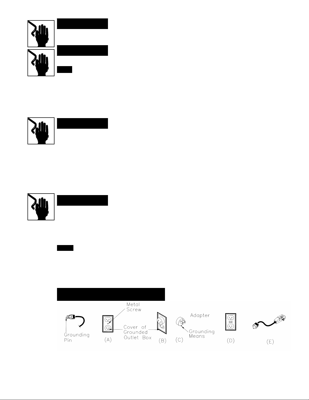
Warning
This tool is intended for use on a circuit that has an outlet that looks like the one illustrated in Sketch A in Figure 1. The tool has
a grounding plug that looks like the plug illustrated in Sketch A in Figure 1. A temporary adapter, which looks like the adapter
illustrated in Sketches B and C, may be used to connect this plug to a 2-pole receptacle as shown in Sketch B if a properly grounded
outlet is not available. The temporary adapter should be used only when a properly grounded outlet is not available. The temporary
adapter should be used only until a properly grounded outlet can be installed by a qualified electrician. The green-colored rigid ear,
lug, and the like, extending f rom the adapter must be connected to a permanent ground such as a properly grounded outlet box.
N o t e
Additionally, the water pump requires the use of a Ground Fault Circuit Interrupter. Therefore, when using the water pump plugged
into the water pump receptacle, this tool must be plugged into a properly installed and grounded Ground Fault Circuit Interrupter
outlet, like the one illustrated in Sketch D in Figure 1. If a Ground Fault Circuit Interrupter outlet is not available, MK Diamond has
available, as an accessory item, a plug - in Ground Fault Circuit Interrupter that may be plugged into a properly installed and
grounded 3-pole outlet. See Sketch E in Figure 1.
Use of a temporary adapter is not permitted in Canada.
Figure 1
Grounding methods
4
Page 6

Extension Cords
Use only extension cords that are intended for outdoor use. These extension cords are identified by a marking of, “Acceptable for
use with outdoor appliances; store indoors while not in use.” Use only extension cords having an electrical rating not less than the
rating of the product. Do not use damaged extension cords, do not “yank” on any cord to disconnect it from the power supply. Keep
cord away from heat and sharp edges. Always disconnect the extension cord from the receptacle before disconnecting the product
from the extension cord.
To reduce the risk of electrocution, keep all connections dry and off the ground. Do not touch plug with wet hands.
Ground Fault Circuit Interrupter (GFCI) protection should be provided on the circuit(s) or outlet(s) to be used for the tile saw.
Receptacles are available having built-in GFCI protection and may be used for this measure of safety.
Notice
Warning
Table 1
Minimum gage for cord
Volts Total length of cord in feet
120V — 25 ft. 50 ft. 100 ft. 150 ft.
Ampere Rating
more than not more than AWG
0 6 18 16 16 14
6 10 18 16 14 12
10 12 16 16 14 12
12 16 14 12 not recommended
Use of undersize extension cords results in low voltage to the motor, which can result in motor burnout and premature
failure. MK Diamond warns that equipment returned to us, showing signs of being run in a low voltage condition through
the use of undersized extension cords, will be repaired or replaced totally at the customer’s expense, there will be no
warranty claim.
240V — 50 ft. 100 ft. 200 ft. 300 ft.
If the plug or receptacle does get wet, DO NOT unplug the cord. Disconnect the fuse or circuit breaker that supplies power to the
tool. Then unplug and examine for presence of water in the receptacle.
power
supply cord
drip loop
To avoid the possibility of the appliance plug or receptacle getting wet, position tile saw to one side of a wall mounted receptacle to
p revent water from dripping onto the receptacle or plug. A “drip loop,” shown in the figure below, should be arranged by the user to
properly position the power cord relative to the power source. The “drip loop” is that part of the cord below the level of the re c e p t a c l e ,
or the connector if an extension cord is used. This method of positioning the cord prevents the travel of water along the power cord and coming
in contact with the receptacle.
Lock Out Method
S awing Operations
General Cutting Guidelines
• A diamond blade does not cut, it grinds. Do not force the tile into the blade, nor feed it to quickly.
• Diamond blades are not all alike. Match the MK blade to the product to be cut.
• B e f o re mounting any blade on the saw, inspect the arbor shaft, flanges and blade for damage or fatigue.
• It is natural for the diamond blade to wear out. Follow MK’s blade recommendations for better longevity and eff i c i e n c y.
• Check that the directional arrow of your MK blade always points in a counter-clockwise direction as it is mounted.
• E n s u re that a continuous flow of water to both sides of the blade occurs during operation.
• Diamond blades need to be sharpened from time-to-time, as this allows for optimum perf o rmance. (See optional accessories.)
• Be sure the blade arbor hole diameter matches the blade shaft.
• Never operate any saw without safety guards in place.
• Do not force the blade into the material: allow the blade to cut all its own speed.
• Do not cut dry with blades designed for wet cutting.
• Do not make long continuous cuts with dry cutting blades: allow the blade to cool by turning the air every few minutes.
• Do not exceed the blades safe operating speed.
• Do not operate the saw with a blade diameter larger than the saws capacity.
5
• Do not cut or grind with the side of the diamond blade, or make radius or curve cuts.
Warning
In order to help prevent accidental starting and to help make your workshop “Kidproof”, this saw is provided
with a means to deactivate the functioning of the motor switch. The switch is provided with a removable
toggle. With the toggle removed the switch does not function, and the motor cannot be turned on. Replacing
the toggle reactivates the switch function. See illustration.
Page 7

n o t i c e
Use only MK DIAMOND authorized brushes to ensure compatibility and avoid motor damage.
For best results use only MK DIAMOND blades.
Warning
Do not attempt to cut pieces too small to hold by hand outside the blade guard. Avoid awkward hand positions where a sudden
slip could cause a hand or fingers to come in contact with the blade. When cutting any material, make sure it is fully supported.
Hold workpiece firmly against the fence. Only feed the material as fast as the blade is able to affectively cut. DO NOT FORCE THE
MATERIAL INTO BLADE!
Rip Cutting
Rip cutting is the term used to describe cutting the material flat on the conveyor table. When cutting the
material on the square, position the rip guide to the desired cutting dimension, and tighten the thumb screw
to secure it in place. Firmly hold the material against the conveyor table back stop and the rip guide while
cutting. When cutting diagonally, position the material using the conveyor table back stop and the optional dual
45° flat angle guide. For cutting materials at other angles, use the 0-90° protractor to align material to the desire d
angle. (See optional accessories, page 5.)
square cut
M a i n t e n a n c e
diagonal cut
Do not attempt to cut pieces too small to hold by hand outside the blade guard. Avoid awkward hand positions
where a sudden slip could cause a hand to move into the blade. When cutting a large piece of material, make
sure it is fully supported. Hold workpiece firmly against conveyor table, back stop and guide. Only feed the
material fast enough for the blade to cut. DO NOT FORCE.
Warning
Conveyor Table Markings
The markings on the conveyor table back stop are used to aid in cutting tile to particular dimensions. The scale on
the top of the back stop is used for setting the rip guide’s diamond window indicator relative to the exact distance
from the diamond blade to the edge of the rip guide. You must first measure the tile for the cut to act as the
standard, and then use the rip guide & table markings to assist in additional cuts.
For your safety, turn ON/OFF switch “OFF” and unplug saw from the power source before performing any maintenance or cleaning.
If the power cord becomes damaged in any way, replace it immediately with the approved cord. When cleaning the saw, DO NOT
let the motor come in direct contact with water. If excessive moisture is introduced to the motor electrical shock could occur and
can cause damage to the internal parts.
DO NOT Service the motor’s internal parts yourself. Contact an authorized MK Service Center, or MK Diamond’s Factory Service
Center for technical support and parts information 1-800-474-5594 for help in solving any problems.
Periodic maintenance your MK-470 allows for long life and tro u b l e - f ree operation. The cutting residue that the saw generates could be
considerable. A cleaning, lubrication and maintenance schedule should be maintained.
R e q u i red maintenance practices include:
• Clean the saw with fresh water after every use.
• Pump clean/fresh water for (1) minute through the water pump and blade guard assembly to safeguard against slurry build-up and
c l o g g i n g .
• Inspect the diamond blade for its overall integrity. Check the rim or segment rim for wear or damage.
• Inspect the wear of the electric motor’s (2) carbon/graphite brushes regularly. The brushes are easily accessible by removing
the brush caps with a flat end screw driver from the square top of the motor. Pull the brushes from their holder and change
them when approximately 1/4" of the brush remains. Use only authorized MK parts.
Trouble Shooting
Warning
For your safety, turn the ON/OFF switch “OFF” and unplug the saw from the power source before perf o rming any troubleshooting pro c e d u re s .
motor problems
Check the power source for 115V.
Check that the circuit breaker from power source is at 20 amp.
Check for correct extension cord gauge/length
Reset Ground Fault Circuit Interrupter (if used)
Check integrity of the carbon/graphite brushes (min. 1/4")
Check the continuity of the ON/OFF switch
6
Page 8

if blade won’t cut properly
table motion
Check that the blade is the correct specification for material being cut.
Check for worn out diamond edge & resharpen as necessary using dressing stick (MK part #152792), and
slowly cut stick in (10) 1/16” slices to redress the diamond blade edge.
Check that blade is rotating in the same direction as the rotation arrow.
Make sure the blade core is not bent.
Check that the guide bar is clean and free of slurry build up. Lubricate guide bar periodically with light machine
oil per maintenance instructions.
Check the condition of the (2) multi-lube bearings & insure they are in good condition.
Check that the saw frame has not been bent.
water flow problems
Optional Accessories
MK-200 The MK-200 blade is a premium continuous rim wet cutting diamond blade (without groves). T h i s
MK-215 The MK-215 blade is a supreme continuous rim wet cutting diamond blade (without groves). It is
MK-315 The MK-315 blade is a super-hi rim continuous rim wet cutting diamond blade (without groves).
Dual 45° flat This guide is used to align the material for diagonal cutting. (part #134569-MK)
angle guide
Check that the water pump vibrates when the motor is on. Reprime pump: Take water hose off blade guard,
remove air bubbles, fully submerse pump outlet in water, turn motor on.
Plug the water pump into an electrical outlet, fully submerse pump in water and check it’s operation.
Check that the water jets in the blade guard are clear, not clogged with hardened slurry or tile particles.
Check that the pump‘s water valve is in the full OPEN position.
blade offers fast cutting on many types of ceramic materials. [part# 139295, 7" (178mm)]
designed with a diamond concentration suited for hard ceramics and soft marble. [part# 139311,
7" (178mm)]
The type and depth of diamond permits longer life and fast cutting on hard vitreous, porcelain tile
as well as marble and granite. [part# 153293, 7" (178mm)]
0-90° Protector This guide is used to align the material for cutting any desired flat angle. (part #134569-MK)
Small 45˚ Bullnose This guide is used to cut 45º miters on bullnose and 1/4 round tile. (part #134585-MK)
Miter Plate
Water Containment Hood This two piece thermoplastic hood controls mist and water for a dry work area, without limiting
visibility. (part #151924-MK)
Ground Fault This accessory (120V/15 AMP) allows the use of a water pump when an outlet mounted GFCI is
Circuit Interrupter
not installed. Easily plugs into a standard 3-pole grounded outlet to convert a ground fault
protected circuit. (part# 152610]
Dressing Stick Specially formulated abrasive stone that permits the fast exposure of new jagged diamonds to the
blade’s periphery and sides. Resharpening of the blade is easily accomplished by cutting multiple
1/16" slivers from the stone. This action quickly redresses the blade, and is especially ideal when
tacking very hard stone and ceramics. [part# 152792]
Saw Stand Sturdy, compact & rugged steel saw stand designed for the MK-470 Tile Saw. The stand easily
affixes to the water reservoir and orients the saw to a comfortable operating height. Easy assembly
& “How-To” instructions are included with the stand. [part# 155953]
7
Page 9

MK-470 Exploded View
B5
L4
L3
L2
L1
G4
X3
H3
H1
J3
X2J2
J1
H2
E2
E3
E4
G1
G2
G3
B3
H5
A3
H5
H4
B4
D3
B4
B2
H6
X4
B1
K1 X2
K2 X2
K3 X2
A7
D1
K4
K8 X2
X2K5
K7
X2
K6 X2
M1
F2 X2
X2F3
X2F4
A1
A2
N4
N3
N1
D2
1
E
1
F
E4
E3
E2
w
a
s
e
l
i
t
Page 10

MK-470 Parts List
Model
MK-470 Tile Saw 120v/7.4a, Part # 155779
Item Description Qt
y
A1 Wrench, Blade Nut, 15/16 Boxed End 1 134684
A2 Wrench, Blade Shaft, 11/16 Open End 1 153450
A3 Blade, 7 Dia X 5/8 Arbor 1 153441
A4* Owner’s Manual 1 156934
A5* Warranty Card 1 155037
A6* Information Tag 1 155844
A7 Assembly, Rip Guide
w/ Screw, _-20 X _ Thumb
B Assembly, Blade Guard, 7” 1 n/a
B1 Guard, Blade, 7” 1 154811-MK
B2 Elbow, 1/8 MNPT X _ BARB 90° Brass 1 154652
B3 Knob, Davies 1 151681
B4 Washer, 5/16 SAE Flat 2 151754
B5 Wingnut, 5/16-18 Nylock 1 151746
D1 Frame 1 155792
D2 Pan, Water 1 155791
D3 Cord Clip, _ Push Mount 1 157259
E Assembly, Guide Bar, 5/8 Dia 1 151739-MK
E1 Bar, Guide, 5/8 Dia 1 151739
E2 Screw, 5/16-18 X 1 Hex Head Cap 2 151743
E3 Washer, 5/16 Split Lock 2 151747
E4 Washer, 5/16 SAE Flat 2 151754
F1 Bearing, Linear, 5/8 Dia 1 157126
F1A Bearing, Multilube 2 151781
F2 Screw, 5/16-18 X 1 Hex Head Cap 2 151743
F3 Washer, 5/16 Split Lock 2 151747
F4 Washer, 5/16 SAE Flat 2 151754
G Assembly, Motor Mount 1 155811-MK
G1 Motor Mount 1 157403
G2 Washer, 5/16 Split Lock 1 151747
G3 Screw, 5/16-18 X 2 1/2 Hex Head Cap, Full Thread 1 151748
G4 Screw, 1/4-20 X 1/2 Flat Head Phillips Cap 3 155812
H1 Motor, 120v/5.3a 1 156428-S
H2 Label, Caution, GFCI, 1 X 2 1/8 1 155678
H3 Label, Caution, Receptacle, 1 X 2 1/8 1 154822
H4 Screw, 10-32 X 5/8 Flat Head Phillips Cap 4 157554
H5 Flange, Blade 2 135830
H6 Nut, 5/8-18 UNF 1 135848
H7 Label, 470 Model 1 156690
J1 Cover, Post 1 155802
J2 Screw, 1/4-20 X 5/16 Socket Head Set 2 154226
J3 Label, Warning, Read Owner’s Manual 1 155806
K Assembly, Roller Wheel Double 1 156586
K1 Screw, 5/16-18 X 1 Hex Head Cap 2 151743
K2 Washer, 5/16 Split Lock 2 151747
K3 Washer, 5/16 SAE Flat 2 151754
K4 Bracket, Roller Wheel 1 156522
1
1
Part #
134551-MK
150991
9
Page 11

K5 Wheel, Roller 2 151799
K6 Screw, 1/4-20 X 1 1/4 Hex Head Cap 2 157145
K7 Washer, 1/4 SAE Flat 2 151915
K8 Nut, 1/4-20 Hex 2 151893
L Assembly, Splash Curtain 1 155901-MK
L1 Curtain, Splash 1 134841
L2 Bracket, Splash Curtain 1 155901
L3 Washer, 1/4 SAE Flat 1 151915
L4 Wingscrew, 1/4-20 X 1/2 1 151888
M Table, 470 1 156536
N Assembly, PES-100 120v Water Pump 1 155987-MK
N1 Pump, Water, PES-100 120v 1 155987
N3 Hose, Vinyl, 1/4 ID 2’ 132951
N4 Clamp, Flow, 1/4-1/2 1 154394
N5* Owner’s Manual, Water Pump 1 155745
*Not shown in exploded view
Rev 12/00
10
Page 12

HOW TO ORDER PARTS
Please have the following information ready before calling:
SERIAL NUMBER OF YOUR SAW
MODELNUMBER OF SAW
WHERE PURCHASED AND WHEN
PARTNUMBER
PARTDESCRIPTION
All parts listed may be ordered from your local distributor or from mk diamond. If the part is not stocked locally, call :1 (800) 421-5830 or (310) 5395221 and ask for customer service. For technical support call: 1 (800) 474-5594 or (310) 257-2845. There is a $25.00 minimum order.
Returned Merchandise Policy
Should you need to return any product you have purchased from MK Diamond, please observe the following:
Our customer service department must be contacted for approval to return merchandise. Merchandise will not be accepted without a RETURNED
GOODS authorization (RGA) number. All returned merchandise must be shipped prepaid to destination, and must have been purchased within the
previous 12 months. A restocking charge of 15% may be billed.
PARA ORDENAR PARTES DE REPUESTO
Sírvase tener lista la siguiente información antes de llamar:
NÚMERO DE SERIE DE LA SIERRA
NÚMERO DE MODELO DE LA SIERRA
DONDE Y CUANDO SE COMPRÓ LA SIERRA
NÚMERO DE LA PARTE
DESCRIPCIÓN LA PARTE
Todas las partes listadas se pueden pedir a través de su distribuidor autorizado o directamente a MK Diamond. Si la parte no está en existencia local,
llame al número de teléfono indicado abajo y pida el departmento de atención al cliente. Para soporte técnio, llame al 1-800-474-5594 sin cargo. El
pedido mínimo es de $25.00.
Política De Devolución De Mercancía
En caso de que sea necesrio devolver algún producto que usted haya comprado a MK Diamond, sívase observar lo siguiente:
Usted debe dirigirse a nuestro departamento de atención al cliente para recibir una aprobación de devolución de mercanía. No se aceptará mercancía
devuelta sin el correspondiente número de pagado hasta su destino. Toda la mercancía devuelta deberá embarcarse con flete meses anteriores y estar
en condiciones de poderse vender como nueva. Se aplicará un cargo de 15% por reintegro al almacén.
POUR COMMANDER LES PIECES DE RECHANGE
Veuillez avoir les informations suivantes avant d'appeler:
NUMÉRO DE SÉRIE DE LA SCIE
NUMÉRO DE MODÈLE DE LA SCIE
DATE ET LIEU D’ACHAT
RÉFÉRENCE
DESIGNATION DE LA PIÈCE
Toutes les pièces indiquées peuvent être commandées auprès de votre distributeur local ou auprès de MK Diamond. Si la pièce n’est pas stockée
localement, veuillez appeler notre numéro d’appel gratuit indiqué ci-dessous et demander le service de la clientèle. Pour support technique, veuillez
contacter le 1 (800) 474-5594. Un minimum de commande 25,00 dollars US est de rigueur.
Politique De Retour De Marchandises
Si vous vous trouvez dans l’obligation de retourner un produit dont vous avez fait l’achat à MK Diamond, veuillez suivre les consignes suivantes:
Notre service de clientèle devrait être consulté pour approbation avant de retourner toute marchandise. La marchandise ne sera en aucun cas acceptée
sans numéro d’autorisation de Marchandises retournées. Toutes les marchandises retournées doivent avoir fait l’objet de l’achat dans les 12 mois
précédents et être en état de revente. Une charge de restockage de 15% sera facturée.
R
MK Diamond Products, Inc.
1315 Storm Parkway. Torrance, CA 90509-2803
1 (800) 421-5830 FAX 1 (310) 539-5158
(310) 539-5221 www.mkdiamond.com
 Loading...