

Page 1
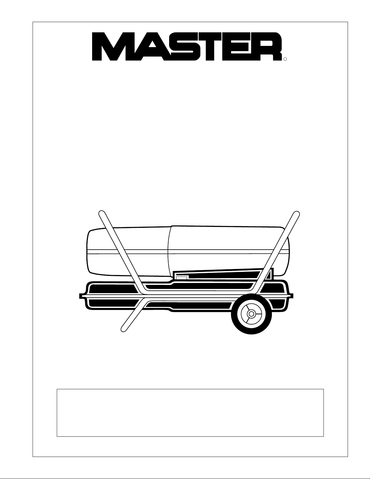
PORTABLE
FORCED
AIR HEATER
OWNER’S MANUAL
R
Model BH150CE
Heater Size: 44 kW (150,000 BTU/Hr)
IMPORTANT
Read and understand this manual before assembling, starting or servicing
heater. Improper use of heater can cause serious injury. Keep this manual
for future reference.
Page 2

CONTENTS
SECTION PAGE
Safety Information.........................................................................3
Product Identification .................................................................... 4
Unpacking......................................................................................4
Assembly .......................................................................................5
Theory of Operation ......................................................................6
Fuels .............................................................................................. 6
Ventilation .....................................................................................7
Operation .......................................................................................7
Storage ........................................................................................... 8
Preventative Maintenance Schedule..............................................8
Troubleshooting.............................................................................9
Service Procedures ........................................................................ 10
Upper Shell Removal .............................................................. 10
Fuel Filter................................................................................10
Spark Plug ............................................................................... 11
Air Output, Air Intake, and Lint Filters ..................................11
Pump Pressure Adjustment ..................................................... 12
Nozzle ..................................................................................... 12
Pump Rotor ............................................................................. 13
Fan...........................................................................................14
Specifications.................................................................................15
Wiring Diagram.............................................................................15
Illustrated Parts Breakdown and Parts List....................................16, 17
Wheels and Handles................................................................ 18
Accessories .................................................................................... 18
Warranty and Repair Service......................................................... Back Cover
2
101487
Page 3
SAFETY
WARNINGS
INFORMATION
IMPORTANT: Read this owner’s manual carefully and completely
before trying to assemble, operate, or service this heater. Improper
use of this heater can cause serious injury or death from burns, fire,
explosion, electrical shock, and carbon monoxide poisoning.
DANGER
Carbon monoxide poisoning may lead to death!
Carbon Monoxide Poisoning: Early signs of carbon monoxide poisoning
resemble the flu, with headaches, dizziness, or nausea. If you have these signs, the
heater may not be working properly. Get fresh air at once! Have heater serviced.
Some people are more affected by carbon monoxide than others. These include
pregnant women, persons with heart or lung disease or anemia, those under the
influence of alcohol, and those at high altitudes.
Make certain you read and understand all warnings. Keep this manual for
reference. It is your guide to safe and proper operation of this heater.
• Use only kerosene or No. 1 fuel oil to avoid risk of fire or explosion. Never
use gasoline, naphtha, paint thinners, alcohol, or other highly flammable
fuels.
• Never use heater where gasoline, paint thinner, or other highly flammable
vapors are present.
• Follow all local ordinances and codes when using heater.
• Use only in well-vented areas. Provide at least a 2800 square cm (3-squarefoot) opening of fresh, outside air for each 29.3 kW (100,000 BTU/Hr) of
rating.
• Use only in places free of flammable vapors or high dust content.
• Use only with the electrical voltage and frequency specified on model plate.
• Use only a three-prong, grounded (earthed) extension cord.
• Minimum heater clearances from combustibles:
Outlet: 250 cm (8 Ft.) Sides, Top, and Rear: 125 cm (4 Ft.)
• Locate heater on a stable and level surface while hot or running or a fire may
occur.
• When moving or storing heater, keep heater in a level position or fuel
spillage may occur.
• Keep children and animals away from heater.
• Unplug heater when not in use.
• When used with thermostat, heater may start anytime.
• Never use heater in living or sleeping areas.
• Never block air inlet (rear) or air outlet (front) of heater.
• Never move, handle, refuel, or service a hot, operating, or plugged-in heater.
• Never attach duct work to front or rear of heater. Using duct work could
reduce the necessary air flow of heater. Heater would produce excessive
carbon monoxide.
101487
3
Page 4
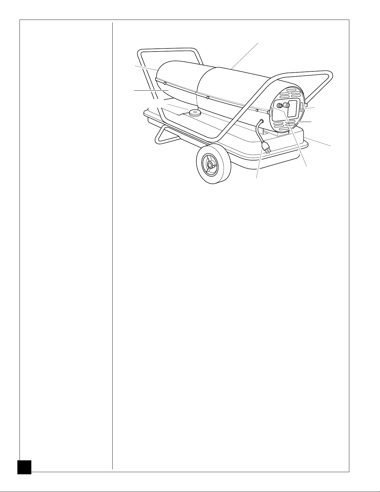
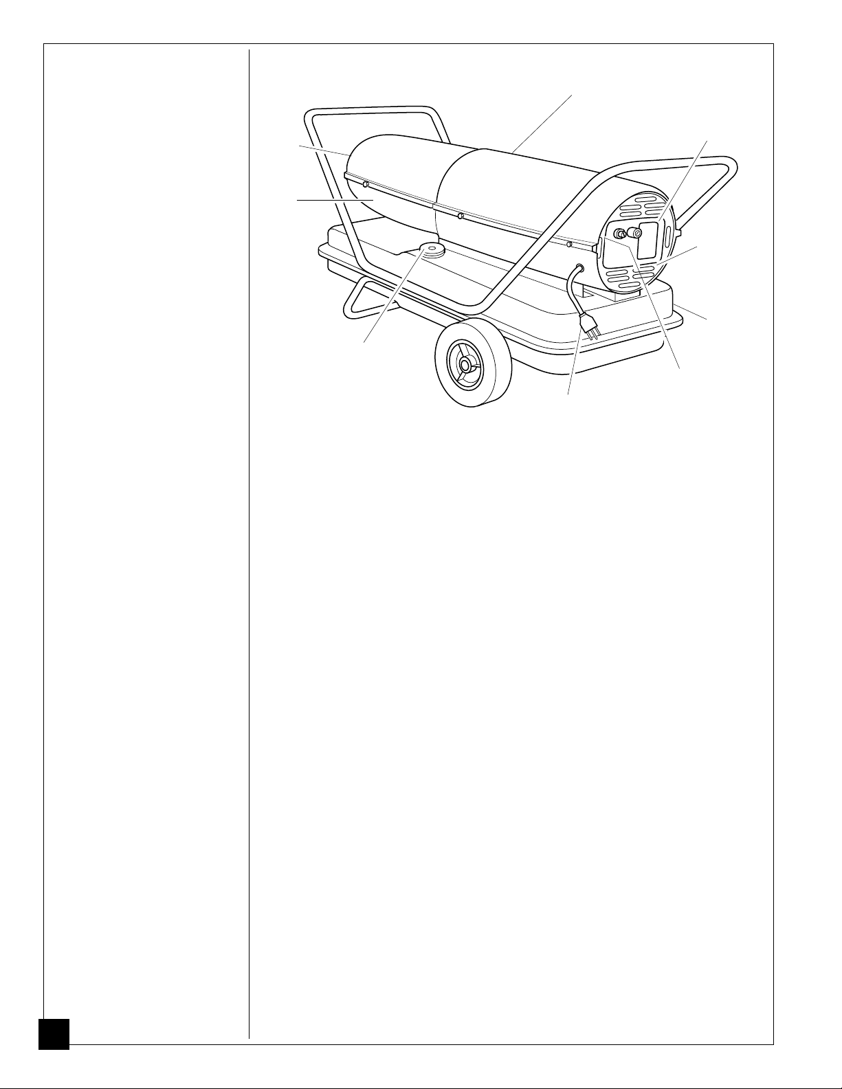
PRODUCT
IDENTIFICATION
Hot Air
Outlet
Lower
Shell
Fuel Cap
Upper Shell
Power Cord
Figure 1 - 44 kW (150,000 BTU/Hr) Model
Air Filter
End Cover
Fan Guard
Fuel
Tank
Flame-Out Control
Reset Button
UNPACKING
1. Remove all packing items applied to heater for shipment.
2. Remove all items from carton.
3. Check items for any shipping damage. If heater is damaged, promptly inform
dealer where you bought heater.
4
101487
Page 5
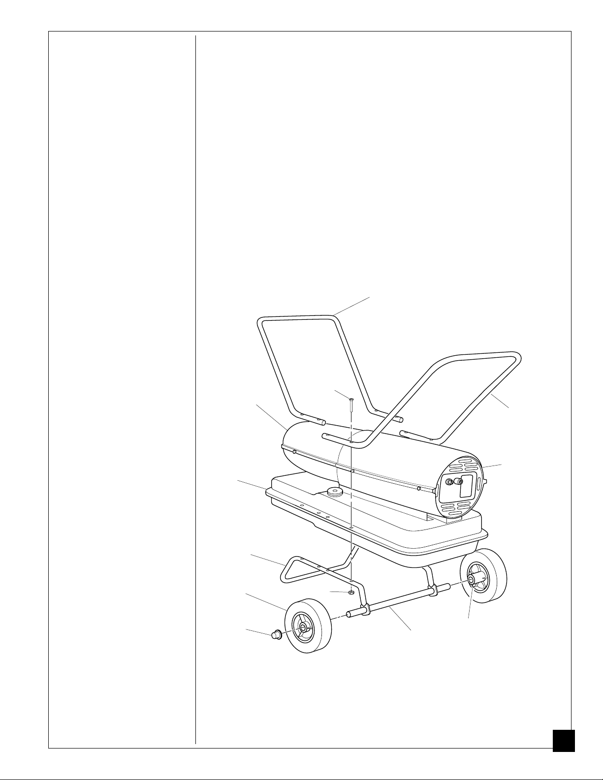
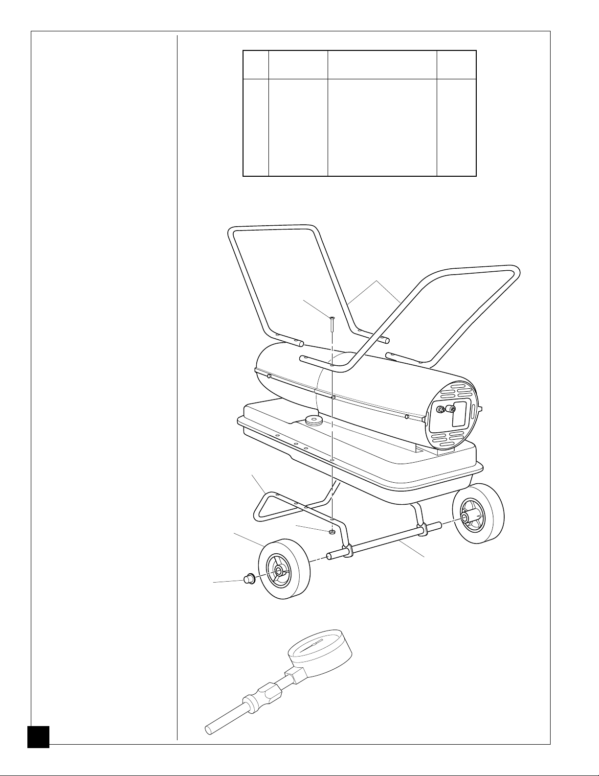
ASSEMBLY
These models are furnished with wheels and handles. Wheels, handles, and the
mounting hardware are found in the shipping carton.
Tools Needed
• Medium Phillips Screwdriver
• 3/8" Open or Adjustable Wrench
• Hammer
1. Slide axle through wheel support frame. Install wheels on axle.
I
MPORTANT:
wheel support frame (see Figure 2).
2. Place cap nuts on axle ends. Gently tap with hammer to secure.
3. Place heater on wheel support frame. Make sure air inlet end (rear) of heater is over
wheels. Line up holes on fuel tank flange with holes on wheel support frame.
4. Place front handle and rear handle on top of fuel tank flange. Insert screws
through handles, fuel tank flange, and wheel support frame. Attach nut finger
tight after each screw is inserted.
5. After all screws are inserted, tighten nuts firmly.
When installing wheels, point extended hub of wheels toward
Front Handle
Hot Air
Outlet
Fuel
Tank
Flange
Wheel
Support
Frame
Wheel
Cap Nut
Screw
Nut
Axle
Rear
Handle
Air
Inlet
Extended
Hub
101487
Figure 2 - Wheel and Handle Assembly
5
Page 6
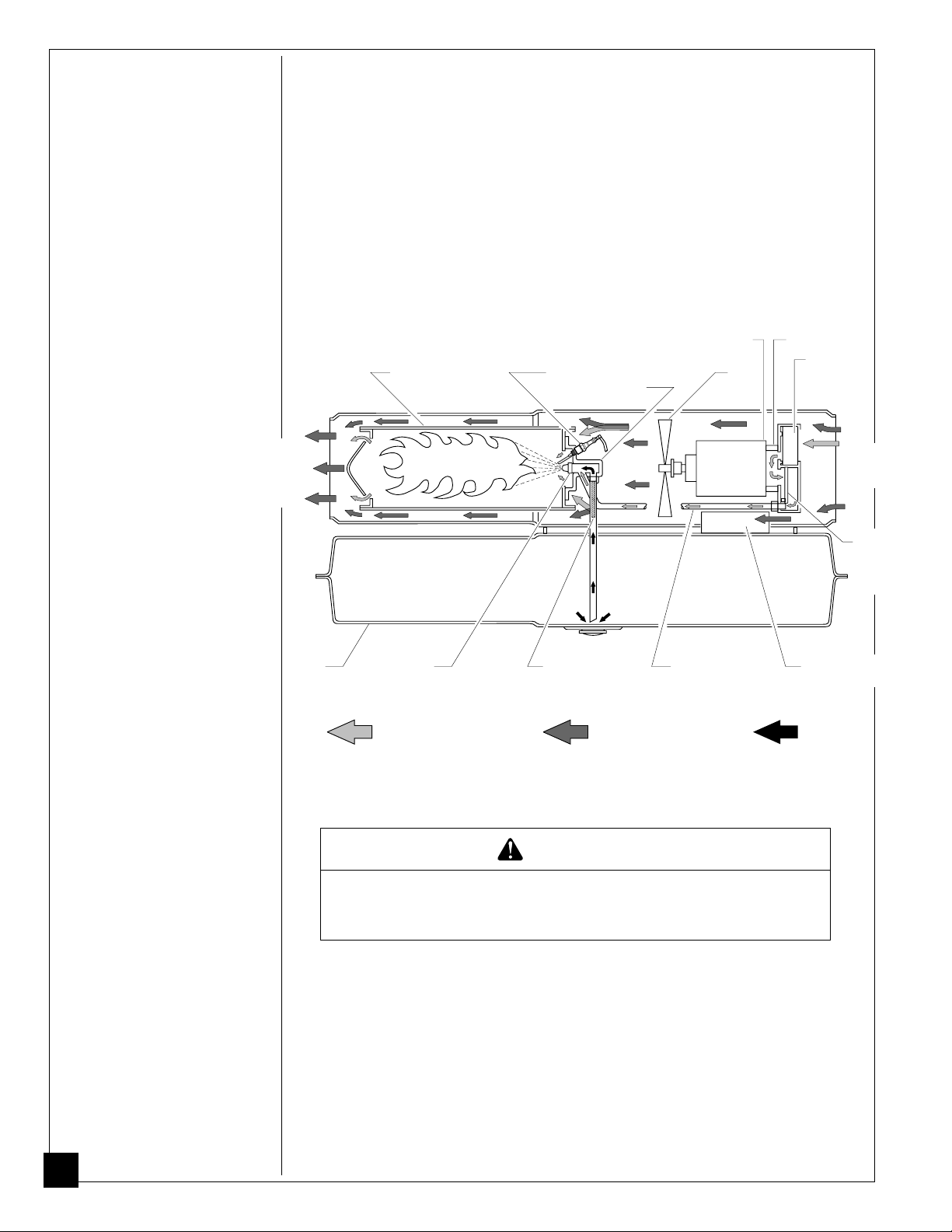
THEORY OF
OPERATION
The Fuel System: The air pump forces air through the air line. The air is then
pushed through the burner head nozzle. This air causes fuel to lift from the tank. A
fine mist of fuel is sprayed into the combustion chamber.
The Air System: The motor turns the fan. The fan pushes air into and around
the combustion chamber. This air is heated and provides a stream of clean, hot air.
The Ignition System: The electronic ignitor sends voltage to the spark plug.
The spark plug ignites the fuel and air mixture.
The Flame-Out Control System: This system causes the heater to shut down
if the flame goes out.
Clean
Heated
Air Out
Fuel
Tank
Combustion
Chamber
Nozzle
Air For Fuel
System
Figure 3 - Cross Section Operational View
Spark
Plug
Fuel
Filter
Motor
Burner
Head
Air line
To Burner
Air For Combustion
And Heating
Fan
Air Pump
Intake
Air
Filter
Cool
Air
In
Output
Air
Filter
Electronic
Ignitor
Fuel
FUELS
WARNING
Use only kerosene or No. 1 fuel oil to avoid risk of fire or
explosion. Never use gasoline, naphtha, paint thinners,
alcohol or other highly flammable fuels.
Do not use heavy fuels such as No. 2 fuel oil or No. 2 Diesel. Using heavy fuels
will result in:
• clogged fuel filter and nozzle
• carbon build up on spark plug
• use of non-toxic anti-icer in fuel during very cold weather
IMPORTANT:
clean. Foreign matter such as rust, dirt, or water will cause the flame-out control to
shut down heater. Foreign matter may also require you to clean fuel system often.
6
Use a KEROSENE ONLY container. Be sure storage container is
101487
Page 7
VENTILATION
WARNING
Follow the minimum fresh, outside air ventilation
requirements. If proper fresh, outside air ventilation is not
provided, carbon monoxide poisoning can occur. Provide
proper fresh, outside air ventilation before running heater.
Provide a fresh air opening of at least 2800 square cm (3 square feet) for each 29.3
kW (100,000 BTU/Hr) rating. Provide extra fresh air if more heaters are being
used.
OPERATION
Example:
A 44 kW (150,000 BTU/Hr) heater requires one of the following:
• a 4.88 m (16 foot) wide two-car garage door raised 8.59 cm (3.38 inches)
• a 2.75 m (9 foot) wide single-car garage door raised 15.24 cm (6 inches)
• two, 76.20 cm (30 inch) wide windows raised 28 cm (11 inches)
WARNING
Review and understand the warnings in the
Information Section.
heater. Follow all local codes when using this heater.
They are needed to safely operate this
To Start Heater
1. Follow all ventilation and safety information.
2. Fill fuel tank with kerosene or No. 1 fuel oil.
3. Attach fuel cap.
4. Plug power cord of heater into standard 230 volt/50 hertz, grounded (earthed)
outlet. Use an extension cord if needed. Use only a three-prong, grounded
(earthed) extension cord.
Extension Cord Wire Size Requirements
Up to 30.5 meters (100 feet) long, use 1.0 mm2 (16 AWG) conductor
30.6 to 61 meters (101 to 200 feet) long, use 1.5 mm2 (14 AWG) conductor
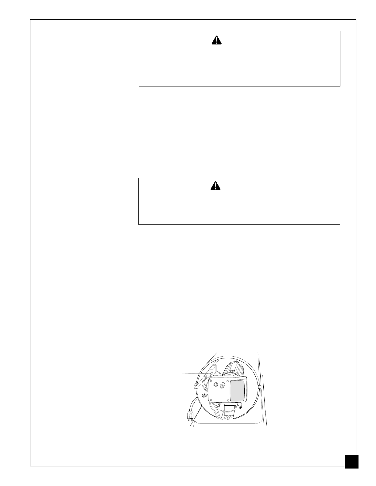
Heater will start when power cord is plugged into outlet. If not, push in flame-
out control reset button (see Figure 4).
Safety
101487
Flame-Out
Control
Reset Button
(Fan Guard
Removed)
Figure 4 - Flame-Out Control Reset Button
Continued
7
Page 8
OPERATION
Continued
To Stop Heater
1. Unplug power cord from outlet.
To Restart Heater
1. Wait 2 minutes after stopping heater.
2. Repeat steps under To Start Heater, page 7.
STORAGE
PREVENTATIVE
MAINTENANCE
SCHEDULE
1. Drain fuel tank.
Note:
Some models have drain plug on underside of fuel tank. If so, remove
drain plug to drain all fuel. If heater does not have drain plug, drain fuel
through fuel cap opening. Be sure all fuel is removed.
2. Replace drain plug if used.
3. Add 4 liters (one gallon) of clean kerosene to fuel tank.
4. Attach fuel cap.
5. Move heater forwards and backwards to stir fuel.
6. Remove fuel cap or drain plug and drain fuel tank. Be sure all fuel is removed.
7. Replace fuel cap or drain plug. Properly dispose of old and dirty fuel.
8. Store heater in dry place. Make sure storage place is free of dust and corrosive
fumes.
IMPORTANT:
heating season. Using old fuel could damage heater.
Do not store kerosene over summer months for use during next
WARNING
Never service heater while it is plugged in, operating, or
hot. Severe burns and electrical shock can occur.
Item How Often How To
Fuel tank Flush every 150-200 hours See Storage above.
of operation or as needed.
Air output and Replace every 500 hours of See Air Output, Air Intake,
lint filters operation or once a year. and Lint Filters, page 11.
Air intake Wash and dry with soap and See Air Output, Air Intake,
filter water every 500 hours of and Lint Filters, page 11.
operation or as needed.
Fuel filter Clean twice a heating season See Fuel Filter, page 10.
or as needed.
Spark plug Clean and regap every 600 See Spark Plug, page 11.
hours operation or replace
as needed.
Fan blades Clean every season or as needed. See Fan, page 14.
Motor Not required/permanently lubricated
8
101487
Page 9
TROUBLE-
SHOOTING
WARNING
Never service heater while it is plugged in, operating, or hot.
Severe burns and electrical shock can occur.
OBSERVED FAULT POSSIBLE CAUSE REMEDY
Heater ignites, but
flame-out control
shuts off heater after
a short period of
time.
Wrong pump pressure
Dirty air output, air intake,
and lint filters
Dirty fuel filter
Dirt in nozzle
Dirty photocell lens
Bad flame-out control
See Pump Pressure
Adjustment, page 12.
See Air Output, Air Intake
and Lint Filters, page 11.
See Fuel Filter, page 10.
See Nozzle, page 12.
Clean photocell lens.
Replace flame-out control.
Heater will not
ignite, but motor runs
for a short period of
time.
Motor does not start
when heater is
plugged in, fan
rotates slowly or
does not turn.
Wrong pump pressure
Carbon deposits on spark
plug and/or improper gap
Dirty fuel filter
Dirt in nozzle
Water in fuel tank
WARNING: High voltage!
Electronic ignitor not
grounded (earthed)
Bad electronic ignitor
Flame-out control not reset
Binding pump rotor
See Pump Pressure
See Spark Plug, page 11.
See Fuel Filter, page 10.
See Nozzle, page 12.
Drain and flush fuel tank
Make sure electronic
Replace electronic
Reset flame-out control
If fan is hard to turn, see
Adjustment, page 12.
with clean kerosene. See
Storage, page 8.
ignitor mounting is tight.
ignitor.
button, see Figure 4,
page 7.
Pump Rotor, page 13.
101487
9
Page 10
SERVICE
PROCEDURES
WARNING
Never service heater while it is plugged in, operating, or
hot. Severe burns and electrical shock can occur.
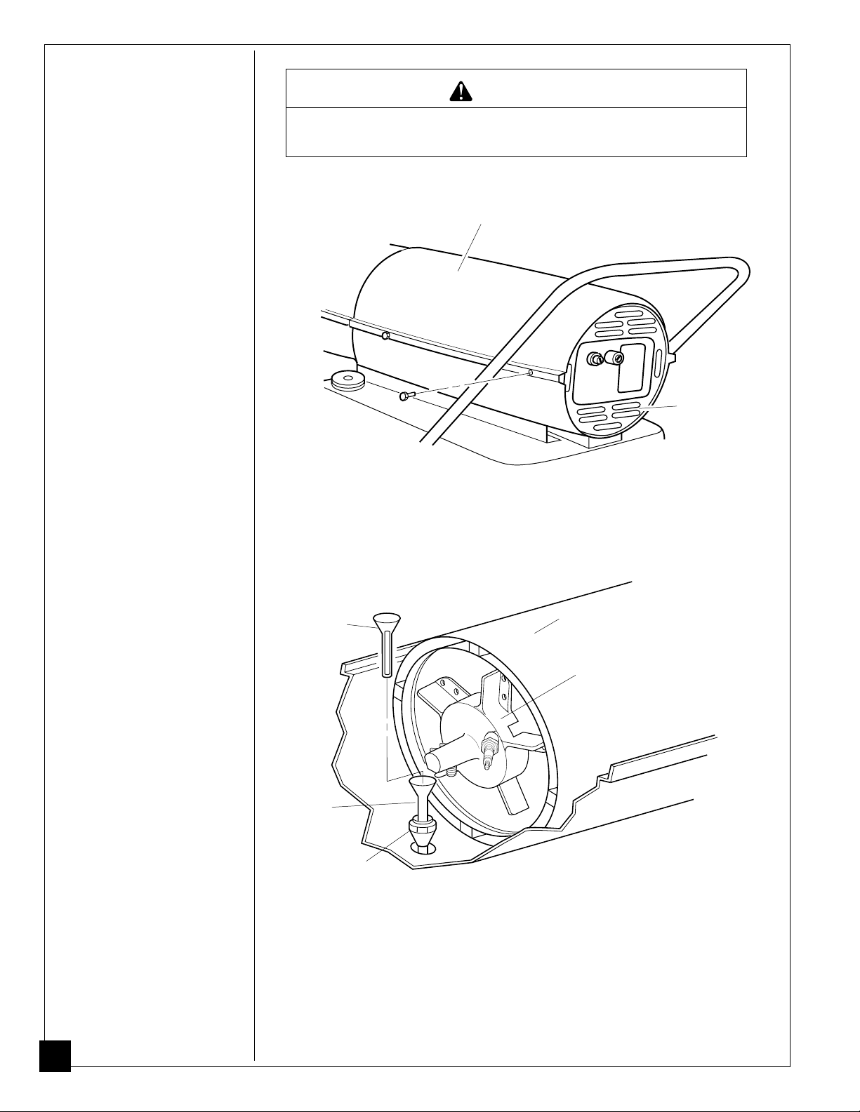
Upper Shell Removal
1. Remove screws along each
side of heater using 5/16"
nut-driver. These screws
attach upper and lower
shells together.
2. Lift upper shell off.
3. Remove fan guard.
Fuel Filter
1. Remove upper shell (see
page 10).
2. Remove fan (see page 14).
3. Loosen flare nut using 3/4"
open-end wrench. Push fuel
tube down, away from
burner head. Fuel filter is
located inside of fuel tube.
4. Lift out fuel filter.
5. Wash fuel filter with clean
fuel and replace in fuel
tube.
6. Connect fuel tube to burner
head. Attach flare nut until
nut seats against fuel tube
and fitting. Tighten 1/4 turn
more using 3/4" open-end
wrench (11.3-14.7 n-m/
100-130 inch-pounds).
7. Replace fan (see page 14).
8. Replace fan guard and
upper shell.
Fuel Filter
Fuel Tube
Flare Nut
Upper
Shell
Fan Guard
Figure 5 - Upper Shell Removal
Combustion
Chamber
Burner
Head
Figure 6 - Fuel Filter Removal
10
101487
Page 11
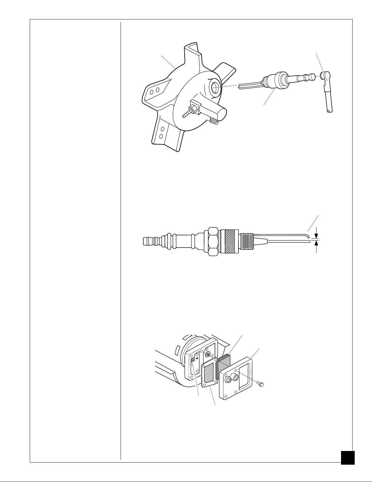
Spark Plug
1. Remove upper shell (see
page 10).
2. Remove fan (see page 14).
3. Remove spark plug wire
from spark plug.
4. Remove spark plug from
burner head using 13/16"
open-end wrench.
5. Clean and regap spark plug
electrodes to 1.4 mm
(.055") gap.
6. Install spark plug in burner
head.
7. Attach spark plug wire to
spark plug.
8. Replace fan (see page 14).
9. Replace fan guard and
upper shell.
Burner
Head
Spark Plug
Wire
Spark
Plug
Figure 7 - Spark Plug Removal
Bend Here
to Adjust
Gap
Air Output, Air Intake,
and Lint Filters
1. Remove upper shell (see
page 10).
2. Remove filter end cover
screws using 5/16" nutdriver.
3. Remove filter end cover.
4. Replace air output and lint
filters.
5. Wash or replace air intake
filter (see Preventative
Maintenance Schedule,
page 8).
6. Replace filter end cover.
7. Replace fan guard and
upper shell.
1.4 mm
(.055" )
Gap
Figure 8 - Spark Plug Gap
Air Intake Filter
Filter End
Cover
Fan Guard
(Not Shown)
Lint Filter
Air Output
Filter
Figure 9 - Air Output, Air Intake, and Lint Filters
IMPORTANT:
101487
Do not oil filters
11
Page 12
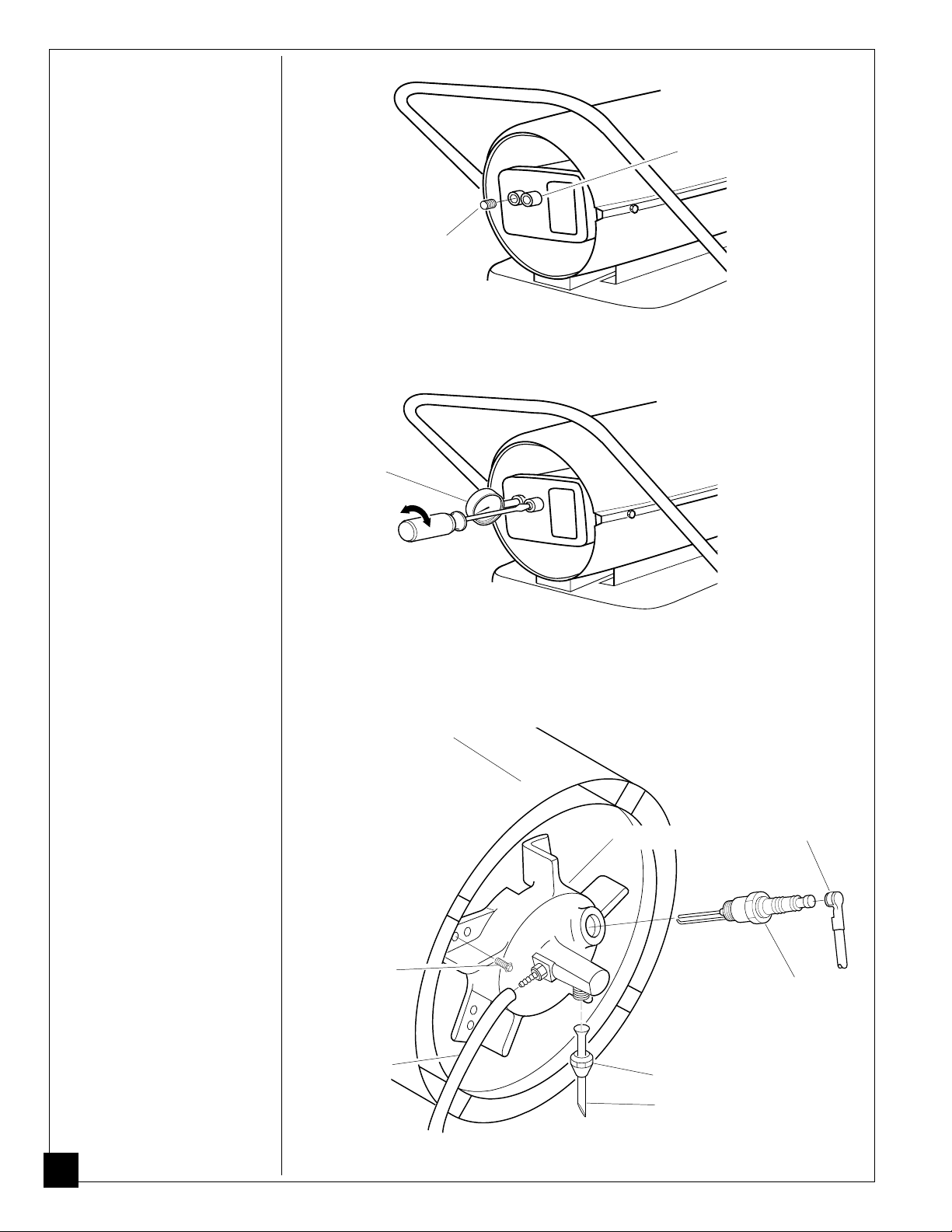
Pump Pressure
g
F
F
Adjustment
1. Remove pressure gauge
plug from filter end cover.
2. Install accessory pressure
gauge (part number
HA1180).
3. Start heater (see Operation,
page 7). Allow motor to
reach full speed.
4. Adjust pressure. Turn relief
valve to right to increase
pressure. Turn relief valve
to left to decrease pressure.
Set pump pressure at 4.9
psi.
5. Remove pressure gauge.
Replace pressure gauge
plug in filter end cover.
Pressure
Gauge
Relief
Valve
Pressure
Gauge
Plug
150 PRESSURE ADJUSTMENT Plu
Figure 10 - Pressure Gauge Plug Removal
P
Nozzle
1. Remove upper shell (see
page 10).
2. Remove fan (see page 14).
3. Remove spark plug wire
from spark plug.
4. Remove spark plug from
burner head using 13/16"
open-end wrench.
5. Loosen flare nut using
3/4" open-end wrench.
Push fuel tube down.
6. Remove air line hose from
burner head.
7. Remove three screws
using 5/16" nut-driver and
remove burner head from
combustion chamber.
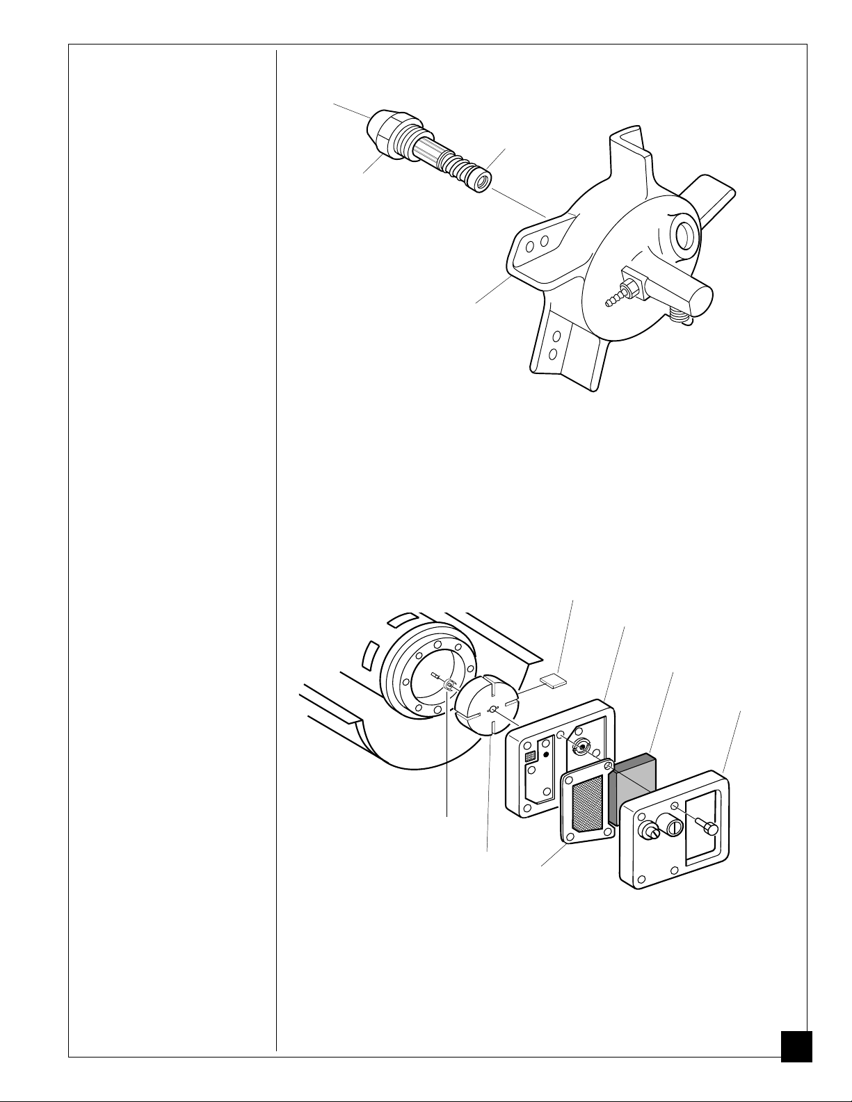
8. Place burner head into vise
and lightly tighten.
9. Carefully remove nozzle
from burner head using
5/8" socket wrench (see
Figure 13).
10. Blow compressed air thru
face of nozzle. This will
free any dirt in nozzle area.
11. Inspect nozzle seal for
damage.
Combustion
Chamber
Screw
Air Line Hose
150 PRESSURE ADJUSTMENT P
Figure 11 - Adjusting Pump Pressure
Burner Head
Flare Nut
Fuel Tube
Spark Plug
Wire
Spark
Plug
12
Figure 12 - Removing Burner Head
101487
Page 13
12.Replace nozzle into burner
head and tighten firmly
(9.1-12.4 n-m/80-110
inch-pounds).
13.Attach burner head to
combustion chamber.
14.Install spark plug in burner
head.
15.Attach spark plug wire to
spark plug.
16.Attach fuel tube and
airline hose to burner
head. Attach flare nut until
nut seats against fuel tube
and fitting. Tighten 1/4
turn more using 3/4" openend wrench (11.3-14.7 nm/100-130 inch-pounds).
17.Replace fan (see page 14).
18.Replace fan guard and
upper shell.
Nozzle
Face
Nozzle
Seal
Nozzle
Burner
Head
Figure 13 - Removing Nozzle
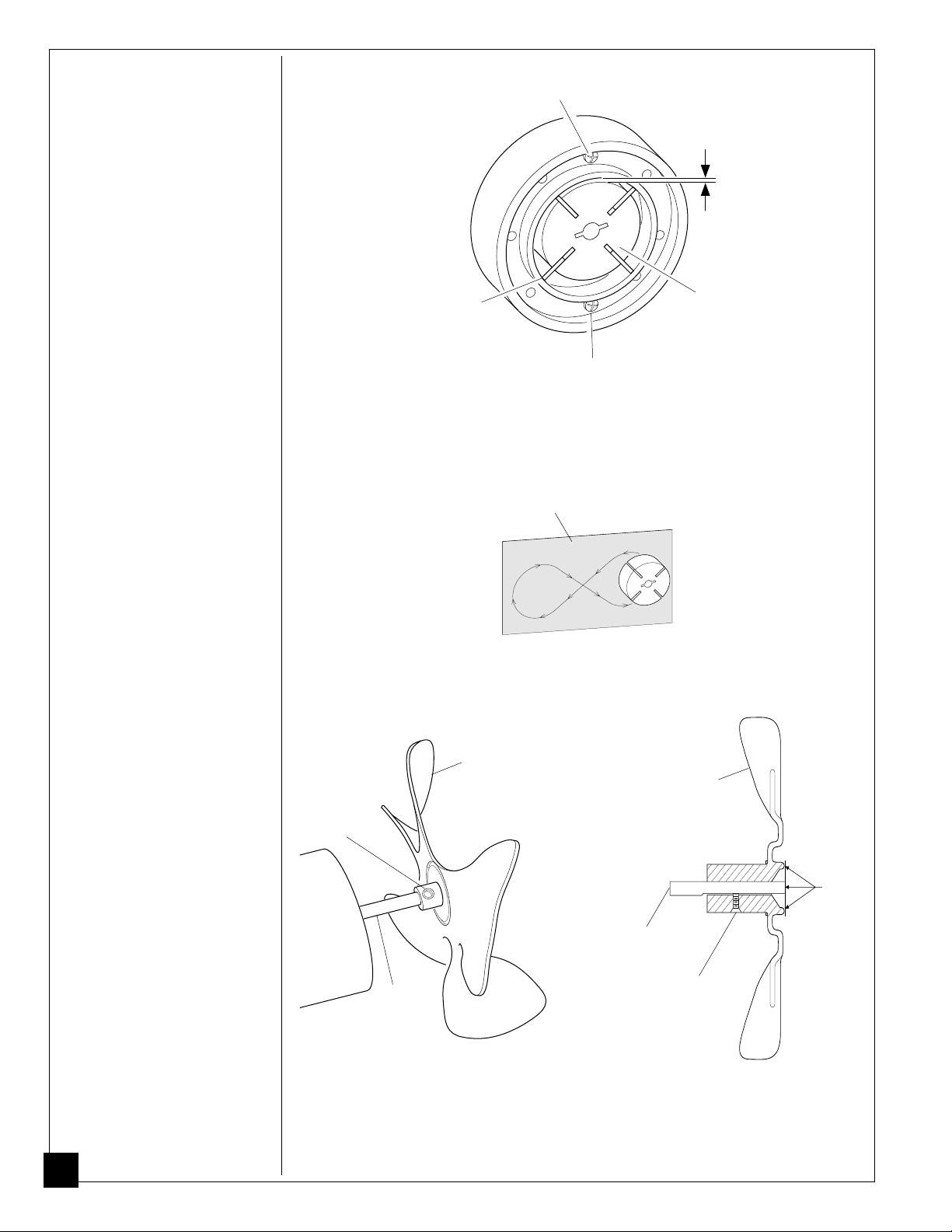
Pump Rotor
(Procedure if rotor is binding)
1. Remove upper shell (see
page 10).
2. Remove filter end cover
screws using 5/16" nutdriver.
3. Remove filter end cover
and air filters.
4. Remove pump plate
screws using 5/16" nutdriver.
5. Remove pump plate.
6. Remove rotor, insert, and
blades.
7. Check for debris in pump.
If debris is found, blow
out with compressed air.
8. Install insert and rotor.
9. Check gap on rotor.
Adjust to .076/.101 mm
(.003"/.004") if needed
(see Figure 15).
Note:
Rotate rotor one
full turn to insure the gap is
.003"/.004" (.076/.101 mm) at
tightest position. Adjust if
needed.
101487
Blade
Insert
Rotor
Figure 14 - Rotor Location
Air
Output
Filter
Pump
Plate
Air
Intake
Filter
Filter End
Cover
Fan Guard
(Not Shown)
13
Page 14
10.Install blades, pump plate,
air filters, and filter end
cover.
11.Replace fan guard and
upper shell.
12.Adjust pump pressure (see
page 12).
Note:
If rotor is still binding,
proceed as follows.
Gap Adjusting
Screw
.076/.101 mm
(.003"/.004") Gap
Measured With
Feeler Gauge
13.Perform steps 1 through 6,
page 13.
14.Place fine grade sandpaper
(600 grit) on flat surface.
Sand rotor lightly in
“figure 8” motion four
times (see Figure 16).
15.Reinstall insert and rotor.
16.Perform steps 10 through
12 above.
Fan
IMPORTANT:
from motor shaft before
removing motor from heater.
The weight of the motor
resting on the fan could
damage the fan pitch.
Remove fan
Blade
Gap
Adjusting
Screw
Figure 15 - Gap Adjusting Screw Locations
Sandpaper
Figure 16 - Sanding Rotor
Rotor
1. Remove upper shell (see
page 10).
2. Use 1/8" allen wrench to
loosen setscrew which
holds fan to motor shaft.
3. Slip fan off motor shaft.
4. Clean fan using a soft cloth
moistened with kerosene or
solvent.
5. Dry fan thoroughly.
6. Replace fan on motor
shaft. Place fan hub flush
with end of motor shaft
(see Figure 18).
7. Place setscrew on flat of
shaft. Tighten setscrew
firmly (4.5-5.6 n-m/40-50
inch-pounds).
8. Replace fan guard and
upper shell.
14
Fan
Setscrew
Motor
Shaft
Figure 17 - Fan, Motor Shaft, and
Setscrew Location
Fan
Flush
Motor
Shaft
Setscrew
Figure 18 - Fan Cross Section
101487
Page 15
SPECIFICATIONS
Output Rating (kW / BTU/Hr) 44kW/150,000
Fuel Use Only Kerosene or No. 1 Fuel Oil
Fuel Tank Capacity
(Liters/U.S. Gal.) 51.09/13.5
Fuel Consumption
(Liters Per Hr./Gal. Per Hr.) 4.16/1.10
Electric Requirements 230 V/50 Hz
Amperage (Normal Run) 1.5
Hot Air Output (CMM/CFM) 17/600
RPM 2850
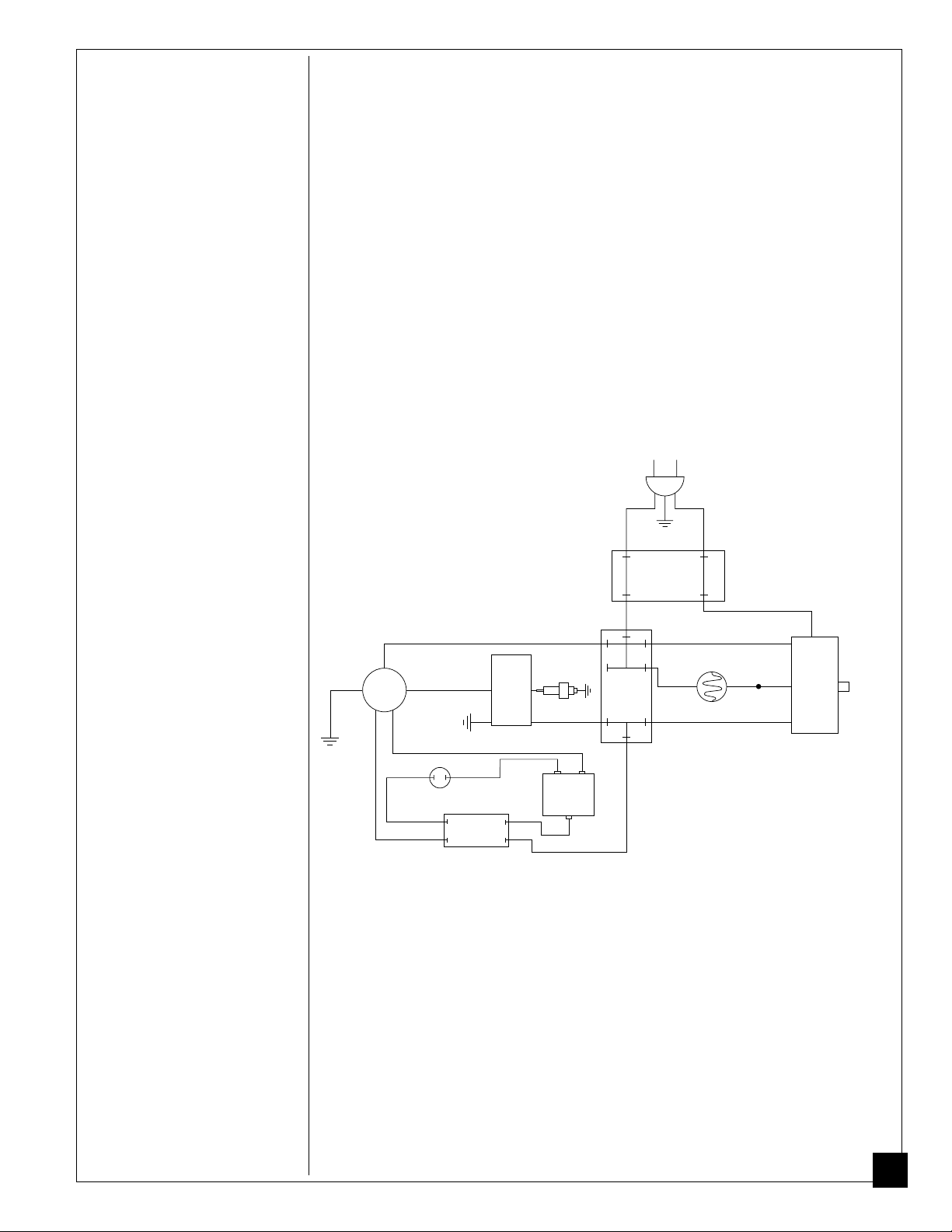
WIRING
DIAGRAM
Green/
Yellow
Motor
Black
Black
Orange
Start
Capacitor
Capacitor
Black
Run
230V/50Hz
Blue
Green/
Yellow
Terminal
Blue
White
Ignitor
Red
S or 2 M or 3
Black
Spark Plug
Motor
Start
Relay
Red
L or 1
Terminal
Board
Red
Figure 19 - Wiring Diagram
Board
White
Brown
Red
Brown
White
Blue
Photocell
Blue
B
Safety
Control
R
Reset
Button
101487
15
Page 16
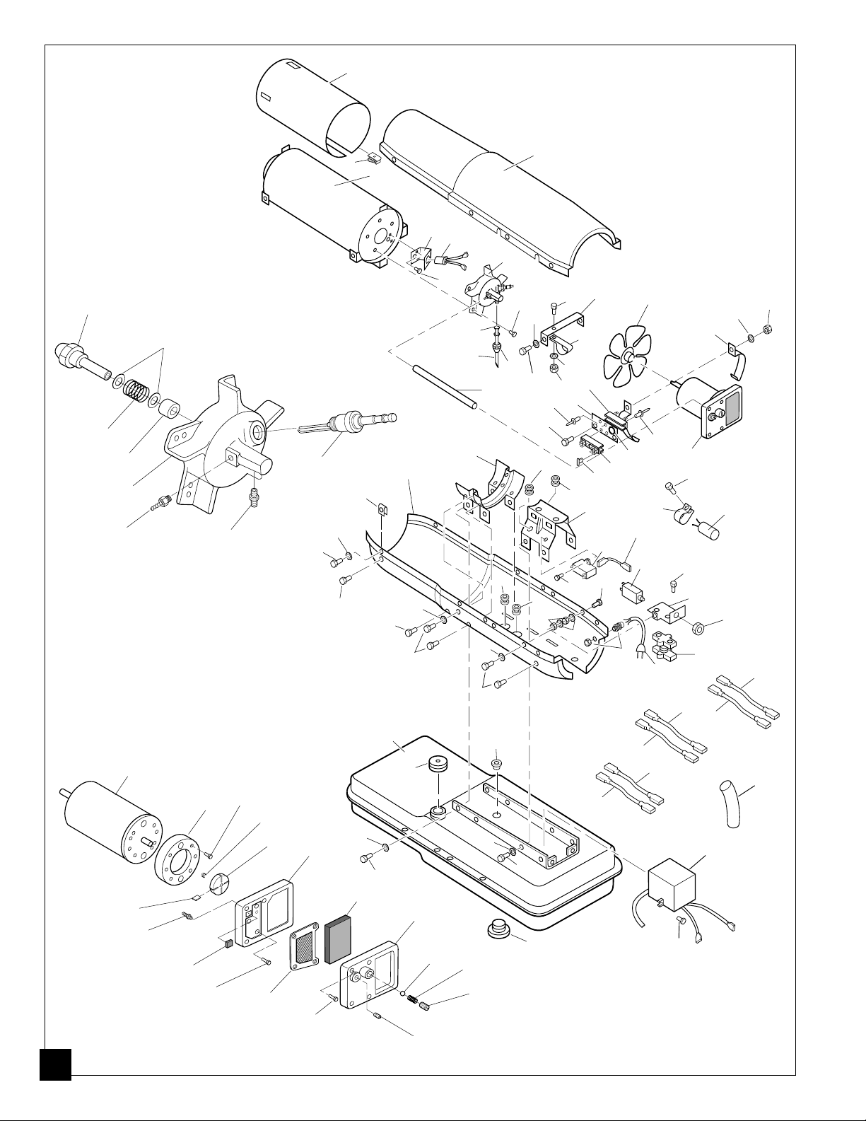
ILLUSTRATED
PARTS
2
BREAKDOWN
8-1
8-2
8-3
8-4
8-5
8-6
Burner Head Assembly
22-1
22-18
22-17
22-16
8-7
22-2
22-15
22-3
22-14
22-4
22-5
8-8
13
22-6
63
32
17
31
63
22-7
1
3
4
5
8
46
9
7
9
63
10
11
12
16
25
30
63
9
32
47
22-8
22-9
63
9
63
22-10
22-11
9
39
21
26
33
33
64
45
9
48
59
56
58
29
38
52
63
57
53
27
50
14
61
28
62
15
20
39
34
23
49
43
22
32
40
9
35
36
37
54
44
26
6
51
42
41
24
65
19
18
55
60
16
22-13
22-12
Motor and Pump Assembly
101487
Page 17
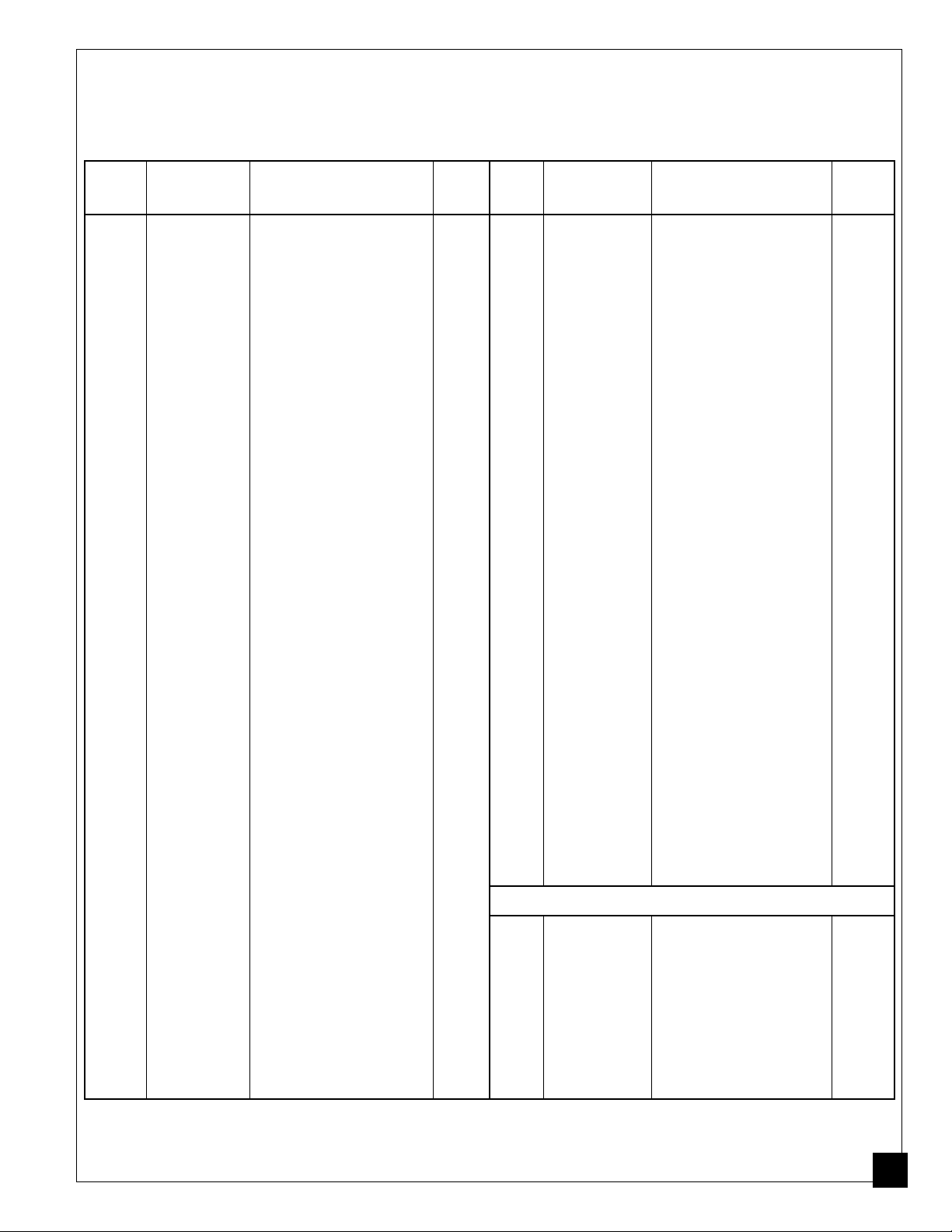
P ARTS LIST
This list contains replaceable parts used in your heater. When ordering parts,
be sure to provide the correct model and serial numbers (from the model plate),
then the part number and description of the desired part.
KEY PART PART
NO. NUMBER DESCRIPTION QTY.
1 098511-58 Upper Shell 1
2 098068-01 Heat Detector 1
3 098512-02 Combustion Chamber 1
4 M16660 Photocell Bracket 1
5 HA3019 Photocell Assembly 1
6 099125-02 Terminal Board 1
7 M10908-2 Screw, #6-32 x 3/8" 2
8 ** Burner Head Assembly 1
8-1 M18022 Nozzle 1
8-2 M10659-1 Nozzle Seal Washer 2
8-3 M10809-1 Nozzle Seal Spring 1
8-4 M8882 Nozzle Seal Sleeve 1
8-5 M50924-01 Burner Head Body 1
8-6 M50820-02 Barb Fitting 1
8-7 079685-01 Male Connector 1
8-8 M10962-2 Spark Plug 1
9 M11084-27 Screw, #10-16 x 1/2" 19
10 M19630 Fuel Filter 1
11 M16790-12 Fuel Tube 1
12 M50660-05 Flared 45° Nut 1
13 100647-01 Screw, #10-16 x 1/2" 8
14 M16871 Retainer Strap 1
15 M17920 Fan 1
16 M50814-03 Air Line 1
17 M50873-01 Clip 9
18 NPC-4C Hex Nut, 1/4-20 2
19 WLM-4 Lockwasher, 1/4" 2
20 M16661-1 Motor Clamp 4
21 M51043-01 Bolt, 1/4-20 x 1 1/2" 2
22 ** Motor and Pump Assembly 1
22-1 098784-03 Motor (230V/50Hz) 1
22-2 079975-04 Pump Body 1
22-3 FHPF3-7C Screw, #10-32 x 7/8" 2
22-4 M22009 Insert 1
22-5 M22456-3 Rotor 1
22-6 M50545 End Pump Cover 1
22-7 M12179 Intake Filter 1
22-8 M16545 End Filter Cover 1
22-9 M8940 Steel Ball (1/4" Dia.) 1
22-10 M10993-1 Pressure Relief Spring 1
22-11 M27694 Adjusting Screw 1
22-12 M22997 Plug 1
22-13 M12461-31 Screw, #10-32 x 1" 4
22-14 M12244-1 Output Filter 1
22-15 M12461-34 Screw, #10-32 x 1 1/2" 6
22-16 M11637 Lint Filter 1
22-17 M50820-02 Barb Fitting 1
22-18 M8643-3 Blade 4
23 M12651-1 Capacitor Clamp 1
24 M12650-3 Capacitor 1
25 M12828 Shell Support Bracket 1
26 M30865-04 Open/Closed Bushing 2
KEY PART PART
NO. NUMBER DESCRIPTION QTY.
27 M16645 Motor Support Bracket 1
28 M51357-01 Capacitor (Run) 1
29 M15823-39 Screw, #8-18 x 1/2" 1
30 M16810-06AB Lower Shell 1
31 M11271-8 Nut Clip 9
32 M11084-29 Screw, #10-16 x 3/4" 8
33 M50104-03 Shorty Bushing 2
34 097630-02 Flame-Out Control 1
35 M12461-13 Screw, #8-32 x 1/4" 2
36 097060-01 Mounting Bracket 1
37 M12462-13 Relay-Motor Start 1
38 099607-02 Terminal Board Bracket 1
39 099157-01 Rivet 2
40 M9900-183 Wire Assembly (black 6") 1
41 M9900-184 Wire Assembly (black 15") 1
42 M50400 Strain Relief Bushing 1
43 079673-03 Power Cord 1
44 098557-07 Electronic Ignitor 1
45 M10990-3 Rubber Bushing 1
46 098513-08 Fuel Tank 1
47 097702-01 Fuel Tank Cap 1
48 M27417 Drain Plug 1
49 079010-14 Wire Assembly (red 8 7/8") 1
50 M9900-77 Wire Assembly (black 15") 1
51 M16841-57 Wire Assembly (red 8 1/2") 1
52 M30865-02 Open/Closed Bushing 1
53 099125-08 Terminal Board 1
54 079010-23 Wire Assembly (blue 9") 1
55 079010-24 Wire Assembly (brown 12") 1
56 M12461-27 Screw, #10-32 x 1/2" 1
57 101488-01 Airline Clamp 1
58 WLM-3 Lock Washer, #10 1
59 NPF-3C Hex Nut, 10-32 1
60 101578-01 Sleeving 1
61 078918-01 Terminal Board Tab Cap 1
62 RF3-5B Screw, #10-32 x 5/8" 1
63 WLE-3 Lock Washer, #10 23
64 NPF-3B Hex Nut, 10-32 2
65 099177-01 Hex Nut, 3/8x27 1
PARTS AVAILABLE - NOT SHOWN
101639-01 Warning Decal 1
098892-02 Fan Guard Bracket 1
M50140 Fan Guard 1
097650-01 Tradename Decal 1
HA2210 Filler Neck Screen 1
098235-25 General Info. Decal
(English & French) 1
098235-26 General Info. Decal
(German & Dutch) 1
**Not available as an assembly, order parts separately.
101487
17
Page 18
WHEELS AND
HANDLES
KEY PART PART
NO. NUMBER DESCRIPTION QTY.
1 HA2205 Handles 2
2 M12345-33 Screw, #10-24 x 1 3/4" 8
3 M12831-3 Wheel Support Frame 1
4 NTC-3C Hex Nut, #10-24 8
5 097896-01 Wheel 2
6 M28526 Cap Nut 2
7 M16801-2 Axle 1
1
2
ACCESSORY
Purchase accessory from your
local dealer.
18
3
5
6
4
7
AIR GAUGE KIT - HA1180
For all models. Special tool to
check pump pressure.
101487
Page 19

NOTES
_______________________________________________________________
_______________________________________________________________
_______________________________________________________________
_______________________________________________________________
_______________________________________________________________
_______________________________________________________________
_______________________________________________________________
_______________________________________________________________
_______________________________________________________________
_______________________________________________________________
_______________________________________________________________
_______________________________________________________________
_______________________________________________________________
_______________________________________________________________
_______________________________________________________________
_______________________________________________________________
_______________________________________________________________
_______________________________________________________________
_______________________________________________________________
_______________________________________________________________
_______________________________________________________________
_______________________________________________________________
_______________________________________________________________
_______________________________________________________________
_______________________________________________________________
_______________________________________________________________
_______________________________________________________________
_______________________________________________________________
_______________________________________________________________
_______________________________________________________________
_______________________________________________________________
_______________________________________________________________
101487
_______________________________________________________________
_______________________________________________________________
_______________________________________________________________
_______________________________________________________________
_______________________________________________________________
_______________________________________________________________
_____________________________________________________________
19
Page 20

WARRANTY AND REPAIR SERVICE
CERTIFICATE OF GENERAL EQUIPMENT -
LIMITED 90 DAY WARRANTY
DESA International warrants new Products sold by it to be
free from defects in material or workmanship for a period of
ninety days after date of delivery to the first user and subject to
the following conditions:
DESA International's obligation and liability under this
Warranty is expressly limited to repairing or replacing at DESA
International's option, any parts which appear to DESA International upon inspection to have been defective in material or
workmanship when shipped from the factory. Such parts shall
be provided at no cost to the user, at the business establishment
of any factory authorized service center or the factory during
regular working hours. The Warranty shall not apply to component parts or accessories of Products not manufactured by
DESA International and which carry the warranty of the manufacturer thereof, or to normal maintenance (such as pressure
adjustments) or to normal maintenance parts (such as filters
and spark plugs). Replacement or repair parts installed in the
Product covered by this Warranty are warranted only for the
remainder of this Warranty as if such parts were original components of said Product. DESA INTERNATIONAL MAKES NO
OTHER EXPRESS WARRANTY. TO THE EXTENT PERMITTED BY LAW DESA INTERNATIONAL MAKES NO IMPLIED
WARRANTY AND MAKES NO WARRANTY OF MERCHANTABILITY OR FITNESS FOR ANY PARTICULAR PUR-
POSE. IN ANY EVENT IMPLIED WARRANTIES INCLUDING
THOSE OF MERCHANTABILITY AND FITNESS FOR A PARTICULAR PURPOSE ARE LIMITED TO THE DURATION OF
THIS EXPRESS WARRANTY.
Any transportation charges, costs of installation, duty,
taxes or any other charges whatsoever must be borne by the
user. DESA International's obligation under this limited Warranty shall not include any liability for direct, indirect, incidental,
or consequential damage or delay. If requested by DESA
International, Products or parts for which a warranty claim is
made are to be returned transportation prepaid by user to the
factory. Any improper use, including operation after discovery
of defective or worn parts, operation beyond capacity, substitution of parts not approved by DESA International, or any
alteration or repair by others in such manner as in DESA
International's judgement affects the Product materially and
adversely, shall void this Warranty.
NO EMPLOYEE OR REPRESENTATIVE IS AUTHORIZED
TO CHANGE THIS WARRANTY IN ANY WAY OR GRANT
ANY OTHER WARRANTY UNLESS SUCH CHANGE IS
MADE IN WRITING AND SIGNED BY AN OFFICER OF DESA
INTERNATIONAL AT ITS HOME OFFICE.
WARRANTY SERVICE
Always specify model and serial numbers when communicating
with the factory.
We reserve the right to amend these specifications at any time
without notice. The only Warranty applicable is our standard
written Warranty. We make no other Warranty, expressed or
implied.
A Service Manual is available by writing to the Technical Service
Department at:
Corporate Headquarters
2701 Industrial Drive
P.O. Box 90004
Bowling Green, KY 42102-9004
U.S.A.
Printed in U.S.A.
20
101487-01
Rev. B
9/94
101487
Page 21
R
APPAREIL DE
CHAUFFAGE
INDIVIDUEL À AIR
FORCÉ
MANUEL D’UTILISATION
Modèle BH150CE
Puissance de l’appareil : 44 kW (150,000 BTU/Hr)
IMPORTANT
Veiller à lire et comprendre ce manuel avant de monter, mettre en marche ou
effectuer l’entretien de cet appareil. Une mauvaise utilisation de cet appareil
pourrait causer des blessures graves. Conserver ce manuel pour s’y reporter
plus tard.
Page 22
TABLE DES
SECTION PAGE
MATIÈRES
Notes sur la sécurité....................................................................... 2
Nomenclature des pièces ............................................................... 4
Déballage ....................................................................................... 4
Montage ......................................................................................... 5
Principes de fonctionnement ......................................................... 6
Carburants...................................................................................... 6
Ventilation ..................................................................................... 7
Fonctionnement ............................................................................. 7
Remisage ....................................................................................... 8
Tableau d’entretien préventif.........................................................8
Dépannage ..................................................................................... 9
Procédures d’entretien ................................................................... 10
Dépose du couvercle ............................................................... 10
Filtre à carburant ..................................................................... 10
Bougie ..................................................................................... 11
Filtres de sortie d’air, d’entrée d’air et à peluche ................... 11
Réglage de la pression de la pompe ........................................ 12
Gicleur..................................................................................... 12
Rotor de la pompe ................................................................... 14
Ventilateur............................................................................... 15
NOTES SUR LA
SÉCURITÉ
Vue éclatée et liste des pièces........................................................16, 17
Roues et guidons ..................................................................... 18
Accessoires .................................................................................... 18
Spécifications ................................................................................ 19
Schéma électrique.......................................................................... 19
Garantie et réparations................................................................... Dos du manuel
AVERTISSEMENTS
IMPORTANT : Veiller à lire ce manuel d’utilisation attentivement et
complètement avant de tenter de monter, de faire fonctionner ou
d’effectuer l’entretien de cet appareil. Une mauvaise utilisation de cet
appareil de chauffage peut causer des blessures graves, voire la mort
par brûlures, incendie, explosion, électrocution et intoxication par
l’oxyde de carbone.
DANGER
L’intoxication par l’oxyde de carbone peut entraîner la mort !
Voir page suivante
2
101487
Page 23
NOTES SUR LA
AVERTISSEMENTS
Suite
SÉCURITÉ
Suite
Intoxication par l’oxyde de carbone : Les premiers signes d’intoxication par
l’oxyde de carbone ressemblent à ceux de la grippe : maux de tête, vertiges ou
nausée. Si l’on ressent ces symptômes, il se peut que l’appareil de chauffage ne
fonctionne pas correctement. Aller immédiatement respirer de l’air frais ! Faire
réparer l’appareil de chauffage. Certaines personnes sont plus susceptibles que
d’autres aux effets de l’oxyde de carbone, par exemple les femmes enceintes, les
personnes souffrant de maladies cardiaques ou pulmonaires, d’anémie, celles sous
l’effet de l’alcool ou celles se trouvant à haute altitude.
Veiller à lire et comprendre tous les avertissements. Conserver ce manuel pour s’y
reporter plus tard. C’est un guide pour l’utilisation correcte et sans danger de cet
appareil de chauffage.
• Ne se servir que de kérosène ou de fioul n 1 pour éviter les risques d’incendie ou
d’explosion. Ne jamais utiliser d’essence, de naphte, de diluants à peinture,
d’alcool ou d’autres combustibles hautement inflammables.
• Ne jamais se servir de l’appareil dans des endroits contenant des vapeurs
d’essence, de diluant à peinture, d’alcool ou d’autres combustibles hautement
inflammables.
• Se conformer à tous les règlements et codes locaux lors de l’utilisation de
l’appareil.
• Ne le faire fonctionner que dans des endroits bien aérés. Une ouverture d’au moins
2800 cm
chaque indice de 29,3 kW (100,000 BTU/Hr) de rendement nominal.
• Ne le faire fonctionner que dans des endroits sans vapeurs inflammables et sans
poussière.
• N’utiliser que les tension et fréquence spécifiées sur la plaque signalétique.
• N’utiliser qu’une rallonge à trois broches avec mise à la terre.
• Distance minimale entre l’appareil et tout matériau combustible :
Sortie : 2,5 m (8 ft) Côtés, dessus et arrière: 1,25 m (4 ft)
• Placer l’appareil de chauffage sur une surface stable et horizontale lorsqu’il est
chaud ou en marche pour éviter de provoquer un incendie.
• Lors du déplacement ou du remisage de l’appareil, le maintenir horizontal pour
éviter de renverser du carburant.
• Maintenir enfants et animaux éloignés de l’appareil de chauffage.
• Débrancher l’appareil lorsqu’on ne s’en sert pas.
• S’il est muni d’un thermostat, l’appareil peut se mettre en marche à n’importe quel
moment.
• Ne jamais utiliser l’appareil dans les salles de séjour ou dans les chambres à
coucher.
• Ne jamais bloquer l’entrée d’air (arrière) ou la sortie d’air (avant) de l’appareil.
• Ne jamais déplacer, manipuler, faire le plein ou effectuer l’entretien d’un appareil
chaud, en marche ou branché.
• Ne jamais monter de canalisation de distribution d’air à l’avant ou à l’arrière de
l’appareil. Cela risquerait de diminuer l’écoulement d’air nécessaire à l’appareil,
qui produirait alors un excès d’oxyde de carbone.
2
(3 sq. ft) laissant passer l’air frais de l’extérieur est nécessaire pour
101487
3
Page 24
NOMENCLA-
Couvercle
TURE DES
PIÈCES
Sortie
d’air
chaud
Boîtier
Bouchon du réservoir
de carburant
Bouton de
Cordon
électrique
Figure 1 - Modèle de 44 kW (150,000 BTU/Hr)
réarmement du
détecteur
d’extinction de
flamme
Cachefiltre
Grille de
protection
du
ventilateur
Réservoir
de
carburant
DÉBALLAGE
1. Retirer tous les emballages de protection utilisés pour le transport.
2. Retirer tous les éléments contenus dans la boîte.
3. Vérifier s’ils ont été endommagés pendant le transport. Si l’appareil est
endommagé, avertir au plus tôt le concessionnaire qui l’a vendu.
4
101487
Page 25

MONTAGE
Ces modèles sont livrés avec des roues et des guidons. Ces derniers et leur
boulonnerie de montage se trouvent dans la boîte d’expédition.
Outils nécessaires
• Tournevis cruciforme de taille moyenne
• Clé plate ou à molette de 3/8 in.
• Marteau
1. Faire passer l’essieu dans le berceau. Installer les roues sur l’essieu.
I
MPORTANT :
berceau (voir figure 2).
2. Placer les écrous borgnes sur les extrémités de l’essieu. Taper légèrement
dessus avec le marteau pour les mettre en place.
3. Placer l’appareil de chauffage sur le berceau. S’assurer que le côté entrée d’air
(arrière) de l’appareil se trouve au-dessus des roues. Aligner les trous du
rebord du réservoir de carburant avec les trous du berceau.
4. Placer les guidons avant et arrière sur le rebord du réservoir de carburant. Faire
passer les vis à travers les guidons, le rebord du réservoir et le berceau. Ceci
fait, serrer à la main un écrou sur chaque vis.
5. Une fois toutes les vis en place, serrer fermement les écrous.
Installer les roues avec le côté allongé du moyeu tourné vers le
Guidon avant
Sortie
d’air
chaud
Rebord
du
réservoir
de
carburant
Berceau
Roue
Écrou
borgne
Vis
Écrou
Essieu
Guidon
arrière
Entrée
d’air
Moyeu
allongé
101487
Figure 2 - Montage des roues et des guidons
5
Page 26

PRINCIPES DE
FONCTION-
NEMENT
Sortie
d’air
chaud
non
pollué
Circuit d’alimentation en carburant : La pompe à air force l’air dans la conduite
d’air. L’air passe ensuite par le gicleur du brûleur. La dépression causée par l’air
fait monter le carburant du réservoir. Un fin nuage de carburant est vaporisé dans
la chambre de combustion.
Circuit d’air : Le moteur fait tourner le ventilateur. Celui-ci pousse l’air dans et
autour de la chambre de combustion. Cet air est chauffé et produit un jet d’air
chaud non pollué.
Dispositif d’allumage : L’allumeur électronique envoie le courant à la bougie.
Celle-ci enflamme le mélange de carburant et d’air.
Détecteur d’extinction de flamme : Ce dispositif arrête l’appareil de chauffage si
la flamme s’éteint.
Chambre de
combustion
Bougie
Moteur
Ventilateur
Brûleur
Pompe à air
Filtre à
air
d’entrée
Entrée
d’air
frais
Filtre
à air
de
sortie
CARBURANTS
6
Réservoir
de
carburant
Gicleur
Air pour le circuit
d’alimentation en
carburant
Figure 3 - Coupe, fonctionnement
Filtre à
carburant
Air de combustion
et de chauffage
Conduite d’air
vers brûleur
Allumeur
électronique
Carburant
AVERTISSEMENT
Ne se servir que de kérosène ou de fioul n 1 pour éviter les
risques d’incendie ou d’explosion. Ne jamais utiliser
d’essence, de naphte, de diluants à peinture, d’alcool ou
d’autres combustibles hautement inflammables.
Ne pas se servir de carburants lourds tels que le fioul n 2 ou le carburant diesel
n 2. L’utilisation de carburants lourds peut donner lieu :
• au colmatage du filtre à carburant et du gicleur
• à l’accumulation de carbone sur la bougie
• au besoin d’ajouter au carburant des produits antigel non toxiques durant les
périodes de grand froid.
IMPORTANT :
KÉROSÈNE. S’assurer que le récipient de stockage est propre. Les matières
étrangères telles que la rouille, la poussière ou l’eau provoquent l’arrêt de
l’appareil par le détecteur d’extinction de flamme. En outre, elles peuvent exiger
un nettoyage plus fréquent du circuit d’alimentation en carburant.
Se servir d’un bidon utilisé EXCLUSIVEMENT pour du
101487
Page 27

VENTILATION
AVERTISSEMENT
Respecter les règles minimales de ventilation en air frais
extérieur. Sans ventilation adéquate en air frais extérieur, il
y a risque d’intoxication par l’oxyde de carbone. S’assurer
que ces règles sont bien suivies avant de faire fonctionner
l’appareil de chauffage.
FONCTION-
NEMENT
Assurer l’entrée d’air frais extérieur par une ouverture d’au moins 2800 cm
ft) pour chaque 29,3 kW (100,000 BTU/Hr) de rendement nominal. Prévoir
davantage d’air frais si plusieurs appareils sont utilisés.
Exemple :
dans l’une des conditions suivantes :
• une porte double de garage de 4,88 m (16 ft) de large relevée de 8,59 cm (3,38 in.)
• une porte simple de garage de 2,75 m (9 ft) de large relevée de 15,24 cm (6 in.)
• deux fenêtres à guillotine de 76,20 cm (30 in.) de large relevées de 28 cm (11 in.)
Un appareil de chauffage de 44 kW (150,000 BTU/Hr) doit fonctionner
2
(3 sq.
AVERTISSEMENT
Veiller à revoir et à bien comprendre les avertissements qui
se trouvent dans la section
nécessaire pour faire fonctionner cet appareil en toute
sécurité. Respecter tous les règlements locaux lors de
l’utilisation de cet appareil.
Mise en marche de l’appareil
1. Suivre les instructions concernant la ventilation et la sécurité.
2. Faire le plein du réservoir avec du kérosène ou du fioul n 1.
3. Remettre le bouchon du réservoir.
4. Brancher le cordon électrique de l’appareil dans une prise standard de 230
Volts et 50 Hz avec prise de terre. Se servir d’une rallonge si nécessaire.
N’utiliser qu’une rallonge à trois broches avec mise à la terre.
Notes sur la sécurité
. Cela est
101487
Conditions requises pour les rallonges électriques
Pour des longueurs atteignant 30,5 m (100 ft), rallonge de calibre 1,0 mm
(16 AWG)
De 30,6 à 61 m (101 à 200 ft), rallonge de calibre 1,5 mm2 (14 AWG)
L’appareil démarre lorsque le cordon électrique est branché dans la prise.
Sinon, appuyer sur le bouton de réarmement du détecteur d’extinction de
flamme (voir figure 4).
Bouton de
réarmement du
détecteur d’extinction
de flamme (Grille de
protection du
ventilateur déposée)
Figure 4 - Bouton de réarmement du détecteur d’extinction de flamme
Voir page suivante
2
7
Page 28

FONCTION-
NEMENT
Suite
Pour arrêter l’appareil de chauffage
1. Débrancher le cordon électrique de la prise.
Pour remettre l’appareil en marche
1. Attendre 2 minutes après l’arrêt de l’appareil.
2. Répéter les opérations indiquées page 7 sous la rubrique Mise en marche.
REMISAGE
TABLEAU
D’ENTRETIEN
PRÉVENTIF
8
1. Vidanger le réservoir de carburant.
Note :
Sur certains modèles, il y a un bouchon de vidange sous le réservoir. Si
c’est le cas, le retirer et vidanger tout le carburant. S’il n’y a pas de bouchon de
vidange, vidanger le carburant par l’orifice de remplissage. S’assurer que tout
le carburant est vidangé.
2. Remettre le bouchon de vidange en place le cas échéant.
3. Verser 4 litres (1 gal.) de kérosène propre dans le réservoir.
4. Remettre le bouchon du réservoir.
5. Déplacer l’appareil d’avant en arrière pour remuer le carburant.
6. Enlever le bouchon du réservoir ou le bouchon de vidange et vidanger le
carburant. S’assurer que tout le carburant est vidangé.
7. Remettre le bouchon du réservoir ou le bouchon de vidange. Se débarrasser du
carburant usé et sale de manière appropriée.
8. Remiser l’appareil dans un endroit sec, à l’abri de la poussière et des vapeurs
corrosives.
IMPORTANT :
période de chauffage suivante. L’usage de carburant ancien risque d’endommager
l’appareil.
Ne pas stocker le kérosène pendant l’été pour l’utiliser durant la
AVERTISSEMENT
Ne jamais effectuer l’entretien de l’appareil de chauffage s’il
est branché, en marche ou chaud. Cela peut entraîner des
brûlures graves ou l’électrocution.
Élément
Réservoir de carburant
Filtres de sortie d’air et
à peluche
Filtre d’entrée d’air
Filtre à carburant
Bougie
Pales du ventilateur
Moteur
Périodicité
Rincer toutes les 150 à 200
heures de fonctionnement
ou selon le besoin.
Remplacer toutes les 500
heures de fonctionnement
ou une fois par an.
Le laver à l’eau savonneuse
et le sécher toutes les 500
heures de fonctionnement
ou selon le besoin.
Le nettoyer deux fois par
période de chauffage ou
selon le besoin.
Nettoyer et régler l’écart
toutes les 600 heures de
fonctionnement ou
remplacer selon le besoin.
Les nettoyer chaque saison
ou selon le besoin.
Aucun entretien nécessaire.
Lubrification permanente.
Opération
Voir Remisage,
ci-dessus.
Voir Filtres de sortie
d’air, d’entrée d’air et
à peluche, page 11.
Voir Filtres de sortie
d’air, d’entrée d’air et
à peluche, page 11.
Voir Filtre à carburant,
page 10.
Voir Bougie, page 11.
Voir Ventilateur, page
15.
101487
Page 29

DÉPANNAGE
AVERTISSEMENT
Ne jamais effectuer l’entretien de l’appareil de chauffage s’il
est branché, en marche ou chaud. Cela peut entraîner des
brûlures graves ou l’électrocution.
ANOMALIE
OBSERVÉE
L’appareil s’allume,
mais le détecteur
d’extinction de
flamme l’arrête après
quelques instants.
L’appareil ne
s’allume pas, mais le
moteur tourne
pendant quelques
instants.
CAUSE
PROBABLE
Pression incorrecte de la
pompe
Filtres de sortie d’air,
d’entrée d’air et à
peluche encrassés
Filtre à carburant
encrassé
Gicleur encrassé
Lentille de cellule
photoélectrique sale
Détecteur d’extinction de
flamme défectueux
Pression incorrecte de la
pompe
Dépôts de carbone sur la
bougie et/ou écart incor-
rect
Filtre à carburant encrassé
Gicleur encrassé
Eau dans le réservoir de
carburant
AVERTISSEMENT : Haute tension !
L’allumeur électronique
n’est pas mis à la masse (à
la terre)
Allumeur électronique
défectueux
REMÈDE
Voir Réglage de la
pression de la pompe,
page 12.
Voir Filtres de sortie
d’air, d’entrée d’air et
à peluche, page 11.
Voir Filtre à carburant,
page 10.
Voir Gicleur, page 12.
La nettoyer.
Le remplacer.
Voir Réglage de la
pression de la pompe,
page 12.
Voir Bougie, page 11.
Voir Filtre à carburant,
page 10.
Voir Gicleur, page 12.
Vidanger et rincer le
réservoir avec du
kérosène propre. Voir
Remisage, page 8.
S’assurer que le montage
de l’allumeur
électronique est bien
serré.
Le remplacer.
101487
Le moteur ne
démarre pas quand
l’appareil est
branché, le
ventilateur tourne
lentement ou pas du
tout.
Le détecteur d’extinction de
flamme n’est pas réarmé
Rotor de pompe grippé
Réarmer le bouton du
détecteur d’extinction
de flamme ; voir figure
4, page 7.
Si le ventilateur tourne
avec difficulté, voir
Rotor de la pompe,
page 14.
9
Page 30

PROCÉDURES
D’ENTRETIEN
AVERTISSEMENT
Ne jamais effectuer l’entretien de l’appareil de chauffage
s’il est branché, en marche ou chaud. Cela peut entraîner
des brûlures graves ou l’électrocution.
Dépose du couvercle
1. Enlever les vis se trouvant
de chaque côté de
l’appareil à l’aide d’une clé
à douille de 5/16 in. Ces
vis retiennent le couvercle
sur le boîtier.
2. Enlever le couvercle.
3. Retirer la grille de protection du ventilateur.
Filtre à carburant
1. Déposer le couvercle (voir
page 10).
2. Déposer le ventilateur (voir
page 15).
3. Desserrer l’écrou évasé à
l’aide d’une clé plate de
3/4 in. Pousser le tube
d’arrivée du carburant vers
le bas pour l’éloigner du
brûleur. Le filtre à
carburant se trouve à
l’intérieur du tube.
4. Retirer le filtre à carburant.
5. Laver le filtre à carburant
avec du carburant propre et
le remettre dans le tube.
6. Brancher le tube sur le
brûleur. Serrer l’écrou
évasé jusqu’à ce qu’il
touche le tube d’arrivée du
carburant et le raccord. Le
serrer d’un quart de tour
supplémentaire avec la clé
plate de 3/4 in. (11,3 à 14,7
Nm [100 à 130 lb.-in.]).
7. Remonter le ventilateur
(voir page 15).
8. Remonter la grille du
ventilateur et le couvercle.
Filtre à
carburant
Tube
d’arrivée
de
carburant
Couvercle
Grille de
protection
du
ventilateur
Figure 5 - Dépose du couvercle
Chambre de
combustion
Brûleur
Écrou
évasé
Figure 6 - Dépose du filtre à carburant
10
101487
Page 31

Bougie
1. Déposer le couvercle (voir
page 10).
2. Déposer le ventilateur (voir
page 15).
3. Débrancher le fil de la
bougie.
4. Retirer la bougie du brûleur
à l’aide d’une clé plate de
13/16 in.
5. Nettoyer les électrodes et
en régler l’écart à 1,4 mm
(.055 in).
6. Remettre la bougie dans le
brûleur.
7. Rebrancher le fil à la
bougie.
8. Remonter le ventilateur
(voir page 15).
9. Remonter la grille de
protection du ventilateur et
le couvercle.
Brûleur
Fil de
bougie
Bougie
Figure 7 - Dépose de la bougie
Plier ici
pour régler
l’écart
Filtres de sortie d’air,
d’entrée d’air et à
peluche
1. Déposer le couvercle
(voir page 10).
2. Retirer les vis du
cache-filtre à l’aide d’une
clé à douille de 5/16 in.
3. Déposer le cache-filtre.
4. Remplacer les filtres de
sortie d’air et à peluche.
5. Laver ou remplacer le
filtre d’entrée d’air (voir
Tableau d’entretien
préventif, page 8).
6. Remonter le cache-filtre.
7. Remonter la grille de
protection du ventilateur
et le couvercle.
IMPORTANT :
les filtres.
101487
Ne pas huiler
Figure 8 - Écart des électrodes de la bougie
Filtre d’entrée d’air
Cache-filtre
Grille de
protection du
ventilateur (non
Filtre à
peluche
Figure 9 - Filtres de sortie d’air, d’entrée d’air et à peluche
Filtre de
sortie d’air
illustrée)
Écart de
1,4 mm
(.055 in.)
11
Page 32

g
F
F
Réglage de la pression
de la pompe
1. Retirer le bouchon du trou
du manomètre du
cache-filtre.
2. Installer le manomètre
(numéro de pièce
HA1180).
3. Mettre l’appareil en
marche (voir
Fonctionnement, page 7).
Attendre que le moteur
atteigne son régime
maximum.
4. Régler la pression. Tourner
le clapet de décharge vers
la droite pour augmenter la
pression et vers la gauche
pour la diminuer. Régler la
pression de la pompe à
33,78 kPa (0,34 bar) (4,9
psi).
5. Retirer le manomètre et
remettre le bouchon du
trou du manomètre sur le
cache-filtre.
Bouchon de
manomètre
Manomètre
Clapet de
décharge
150 PRESSURE ADJUSTMENT Plu
Figure 10 - Dépose du bouchon du trou du manomètre
150 PRESSURE ADJUSTMENT P
Figure 11 - Réglage de la pression de la pompe
P
Gicleur
1. Déposer le couvercle (voir
page 10).
2. Déposer le ventilateur
(voir page 15).
3. Détacher le fil de la
bougie.
4. Retirer la bougie du
brûleur à l’aide d’une clé
plate de 13/16 in.
5. Desserrer l’écrou évasé à
l’aide d’une clé plate de
3/4 in. Pousser le tube
d’arrivée de carburant vers
le bas.
6. Débrancher du brûleur le
flexible de la conduite
d’air.
7. Enlever les trois vis à
l’aide d’une clé à douille
de 5/16 in. et enlever le
brûleur de la chambre de
combustion.
12
Chambre de
combustion
Vis
Flexible de
conduite d’air
Brûleur
Écrou évasé
Tube d’arrivée du
carburant
Figure 12 - Dépose du brûleur
Fil de
bougie
Bougie
101487
Page 33

8. Placer le brûleur dans un
étau et le serrer
légèrement.
9. Enlever avec précaution le
gicleur du brûleur à l’aide
d’une clé à pipe de 5/8 in.
(voir figure 13).
10.Souffler de l’air comprimé
par l’avant du gicleur pour
en déloger toute saleté.
11.Vérifier le bon état du
joint d’étanchéité du
gicleur.
12.Remettre le gicleur dans le
brûleur et le serrer
fermement (9,1 à 12,4 Nm
[80 à 100 lb.-in.]).
13.Remonter le brûleur sur la
chambre de combustion.
14.Poser la bougie dans le
brûleur.
15.Rebrancher le fil à la
bougie.
16.Rebrancher le tube
d’arrivée du carburant et le
flexible de la conduite
d’air au brûleur. Serrer
l’écrou évasé jusqu’à ce
qu’il touche le tube
d’arrivée du carburant et le
raccord. Le serrer d’un
quart de tour
supplémentaire avec la clé
plate de 3/4 in. (11,3 à
14,7 Nm [100 à 130 lb.in.]).
17.Remonter le ventilateur
(voir page 15).
18.Remonter la grille de
protection du ventilateur et
le couvercle.
Avant
du
gicleur
Joint
d’étanchéité
du gicleur
Gicleur
Brûleur
Figure 13 - Dépose du gicleur
101487
13
Page 34

Rotor de la pompe
(Procédure en cas de grippage)
1. Déposer le couvercle (voir
page 10).
2. Retirer les vis du
cache-filtre à l’aide d’une
clé à douille de 5/16 in.
3. Déposer le cache-filtre et
les filtres à air.
4. Retirer les vis de la plaque
de la pompe à l’aide d’une
clé à douille de 5/16 in.
5. Déposer la plaque de la
pompe.
6. Enlever rotor, pièce
encastrée et pales.
7. Vérifier s’il y a des corps
étrangers dans la pompe.
S’il y en a, les chasser à
l’air comprimé.
8. Installer la pièce encastrée
et le rotor.
9. Vérifier le dégagement du
rotor. Si nécessaire, le
régler de 0,076 à 0,101
mm (.003 à .004 in.) (voir
figure 15).
Note :
Faire faire un tour
complet au moteur pour
s’assurer que l’écart à
l’endroit le plus serré est de
0,076 à 0,101 mm (.003 à
.004 in.). Refaire le réglage si
nécessaire.
10.Remonter pales, plaque de
pompe, filtres à air et
cache-filtre.
11.Remonter la grille de
protection et le couvercle.
12.Régler la pression de la
pompe (voir page 12).
Pale
Pièce
encastrée
Rotor
Filtre de
sortie d’air
Figure 14 - Emplacement du rotor
Vis de réglage
de l’écart
Pale
Vis de
réglage
de l’écart
Figure 15 - Emplacement des vis de réglage de l’écart
Plaque de
pompe
Filtre
d’entrée
d’air
Grille de
protection du
ventilateur (non
illustrée)
Écart de 0,076 à
0,101 mm (.003 à
.004 in.) mesuré
avec une jauge
d’épaisseur
Rotor
Cache-filtre
Note :
Si le rotor est toujours
grippé, procéder comme suit.
13.Effectuer les opérations 1
à 6 ci-dessus.
14
Papier de
verre
Figure 16 - Ponçage du rotor
101487
Page 35

14.Placer une feuille de
papier de verre fin (600)
sur une surface plate.
Poncer légèrement le rotor
sur la feuille d’un
mouvement en forme de
« 8 » (voir figure 16).
Répéter quatre fois.
15.Remonter la pièce
encastrée et le rotor.
16.Effectuer les opérations 10
à 12 (voir page 14).
Ventilateur
IMPORTANT :
ventilateur de l’arbre du
moteur avant de retirer ce
dernier de l’appareil. Le poids
du moteur sur le ventilateur
peut en fausser les pales.
1. Déposer le couvercle (voir
page 10).
2. Utiliser une clé coudée de
1/8 in. pour desserrer la
vis d’arrêt qui maintient le
ventilateur sur l’arbre du
moteur.
3. Retirer le ventilateur en le
faisant glisser sur l’arbre
du moteur.
4. Nettoyer le ventilateur
avec un chiffon propre
préalablement mouillé
avec du kérosène ou du
diluant.
5. Sécher complètement le
ventilateur.
6. Replacer le ventilateur sur
l’arbre du moteur. Placer
le moyeu du ventilateur au
ras de l’extrémité de
l’arbre du moteur (voir
figure 18).
7. Positionner la vis d’arrêt
sur le méplat de l’arbre. La
serrer fermement (de 4,5 à
5,6 Nm/40 à 50 in-lb).
8. Remonter la grille de
protection du ventilateur et
le couvercle.
101487
Retirer le
Ventilateur
Vis d’arrêt
Arbre du
moteur
Figure 17 - Emplacement du ventilateur,
de l’arbre du moteur et de la vis d’arrêt
Ventilateur
Au
ras
Arbre du
moteur
Vis d’arrêt
Figure 18 - Coupe du ventilateur
15
Page 36

VUE ÉCLATÉE
8-1
8-2
8-3
8-4
8-5
8-6
Ensemble brûleur
22-1
22-18
22-17
22-16
22-2
22-15
8-7
22-3
22-4
22-14
22-5
8-8
13
22-6
63
32
17
2
31
63
22-7
1
3
4
5
8
7
14
10
11
16
12
9
56
63
57
58
9
39
59
53
38
15
20
19
18
21
39
22
9
30
25
26
61
26
6
52
27
23
24
51
28
34
33
63
9
33
64
63
32
29
63
62
42
43
35
36
65
37
55
9
40
54
46
47
45
41
49
60
50
63
9
22-8
9
48
22-9
22-10
22-11
44
32
16
Ensemble moteur et pompe
22-13
22-12
101487
Page 37

LISTE DES
PIÈCES
Cette liste comprend les pièces de l’appareil de chauffage qui peuvent être
remplacées. Lors de la commande de pièces détachées, veiller à inclure le
numéro de modèle et les numéros de série corrects (pris sur la plaque
signalétique), puis le numéro de pièce et la désignation de la pièce désirée.
N DE NUMÉRO
RÉF. DE PIÈCE DÉSIGNATION QTÉ
1 098511-58 Couvercle 1
2 098068-01 Bouclier thermique 1
3 098512-02 Chambre de combustion 1
4 M16660 Support de cellule
photoélectrique 1
5 HA3019 Ensemble cellule
photoélectrique 1
6 099125-02 Planche à bornes 1
7 M10908-2 Vis n 6-32 x 3/8 in. 2
8 ** Ensemble brûleur 1
8-1 M18022 Gicleur 1
8-2 M10659-1 Rondelle d’étanchéité de gicleur 2
8-3 M10809-1 Ressort d’étanchéité de gicleur 1
8-4 M8882 Manchon d’étanchéité
de gicleur 1
8-5 M50924-01 Corps de brûleur 1
8-6 M50820-02 Raccord à griffes 1
8-7 079685-01 Connecteur mâle 1
8-8 M10962-2 Bougie 1
9 M11084-27 Vis n 10-16 x 1/2 in. 19
10 M19630 Filtre à carburant 1
11 M16790-12 Tube de carburant 1
12 M50660-05 Écrou évasé à 45 1
13 100647-01 Vis n 10-16 x 1/2 in. 8
14 M16871 Bande de retenue 1
15 M17920 Ventilateur 1
16 M50814-03 Conduite d’air 1
17 M50873-01 Attache 9
18 NPC-4C Écrou hexagonal, 1/4-20 2
19 WLM-4 Rondelle de blocage, 1/4 in. 2
20 M16661-1 Attache de moteur 4
21 M51043-01 Boulon 1/4-20 x 1 1/2 in. 2
22 ** Ensemble moteur et pompe 1
22-1 098784-03 Moteur (230 V/50 Hz) 1
22-2 079975-04 Corps de pompe 1
22-3 FHPF3-7C Vis n 10-32 x 7/8 in. 2
22-4 M22009 Pièce encastrée 1
22-5 M22456-3 Rotor 1
22-6 M50545 Couvercle de pompe 1
22-7 M12179 Filtre d’entrée 1
22-8 M16545 Cache-filtre 1
22-9 M8940 Bille en acier (1/4 in. de diam.) 1
22-10 M10993-1 Ressort de décharge
de pression 1
22-11 M27694 Vis de réglage 1
22-12 M22997 Bouchon 1
22-13 M12461-31 Vis n 10-32 x 1 in. 4
22-14 M12244-1 Filtre de sortie 1
22-15 M12461-34 Vis n 10-32 x 1 1/2 in. 6
22-16 M11637 Filtre à peluche 1
22-17 M50820-02 Raccord à griffes 1
22-18 M8643-3 Pale 4
23 M12651-1 Bride de condensateur 1
24 M12650-3 Condensateur 1
25 M12828 Support de boîtier 1
26 M30865-04 Bague fermée/ouverte 2
27 M16645 Support de moteur 1
N DE NUMÉRO
RÉF. DE PIÈCE DÉSIGNATION QTÉ
28 M51357-01 Condensateur (marche) 1
29 M15823-39 Vis n 8-18 x 1/2 in. 1
30 M16810-06AB Boîtier 1
31 M11271-8 Attache 9
32 M11084-29 Vis n 10-16 x 3/4 in. 8
33 M50104-03 Bague courte 2
34 097630-02 Détecteur d’extinction
de flamme 1
35 M12461-13 Vis n 8-32 x 1/4 in. 2
36 097060-01 Ferrure de montage 1
37 M12462-13 Relais - démarrage du moteur 1
38 099607-02 Ferrure de planche à bornes 1
39 099157-01 Rivet 2
40 M9900-183 Ensemble de fil (noir 6 in.) 1
41 M9900-184 Ensemble de fil (noir 15 in.) 1
42 M50400 Bague anti-tension 1
43 079673-03 Cordon électrique 1
44 098557-07 Allumeur électronique 1
45 M10990-3 Bague en caoutchouc 1
46 098513-08 Réservoir de carburant 1
47 097702-01 Bouchon de réservoir
de carburant 1
48 M27417 Bouchon de vidange 1
49 079010-14 Ensemble de fil (rouge 8 7/8 in.) 1
50 M9900-77 Ensemble de fil (noir 15 in.) 1
51 M16841-57 Ensemble de fil (rouge 8 1/2 in.) 1
52 M30865-02 Bague ouverte/fermée 1
53 099125-08 Planche à bornes 1
54 079010-23 Ensemble de fil (bleu 9 in.) 1
55 079010-24 Ensemble de fil (marron 12 in.) 1
56 M12461-27 Vis n 10-32 x 1/2 in. 1
57 101488-01 Collier de conduite d’air 1
58 WLM-3 Rondelle de blocage n 10 1
59 NPF-3C Écrou hexagonal, 10-32 1
60 101578-01 Matériau de gainage 1
61 078918-01 Fiche de planche à bornes 1
62 RF3-5B Vis n 10-32 x 5/8 in. 1
63 WLE-3 Rondelle de blocage n 10 23
64 NPF-3B Écrou hexagonal, 10-32 2
65 099177-01 Écrou hexagonal, 3/8x27 1
PIÈCES DISPONIBLES - NON ILLUSTRÉES
101639-01 Autrocollant d’avertissement 1
098892-02 Support de grille de protection
de ventilateur 1
M50140 Grille de protection
de ventilateur 1
097650-01 Autocollant de marque déposée 1
HA2210 Crépine de goulotte de
remplissage 1
098235-25 Autocollant d’informations
générales (Anglais et français) 1
098235-26 Autocollant d’informations
générales (Allemand et
néerlandais) 1
**N’est pas disponible monté, commander les pièces séparément.
101487
17
Page 38

ROUES ET
GUIDONS
N NUMÉRO
RÉF DE PIÈCE DÉSIGNATION QTÉ
1 HA2205 Guidons 2
2 M12345-33 Vis n 110-24 x 1 3/4 in. 8
3 M12831-3 Berceau 1
4 NTC-3C Écrou hexagonal n 10-24 8
5 097896-01 Roue 2
6 M28526 Écrou borgne 2
7 M16801-2 Essieu 1
1
2
ACCESSOIRE
Se procurer les accessoires
auprès du concessionnaire
18
local.
3
5
6
4
7
JEU DE MANOMÈTRE - HA1180
Pour tous les modèles. Outil
conçu pour vérifier la pression de
la pompe.
101487
Page 39

SPÉCIFICA TIONS
SCHÉMA
Rendement nominal de sortie (kW/BTU/Hr) 44 kW/150 000
Carburant N’employer que du
kérosène ou du fioul n 1
Contenance du réservoir de carburant (l/U.S. Gal.) 51,09/13.5
Consommation de carburant (l/h/Gal./h) 4,16/1.10
Électricité requise 230 V/50 Hz
Intensité (A) (Fonctionnement normal) 1,5
3
Débit d’air chaud (m
/min ; ft3/min) 17/600
Régime moteur (tr/min) 2850
230V/50Hz
ÉLECTRIQUE
Vert/
Jaune
Moteur
Noir
Orange
Noir
Allumeur
Rouge
Noir
Condesateur
de démarrage
Condensateur
de marche
S ou 2
Noir
Blanc
Bougie
Rouge
Relais de
démarrage
du moteur
L ou 1
Bleur
Planche
à bornes
M ou 3
Bleur
Rouge
Vert/
Jaune
Planche
à bornes
Blanc
Rouge
Marron
Cellule
Photoélectrique
Bleur
Marron
Blanc
Bleur
B
Détecteur
d'extinction
de flamme
R
Bouton de
réarmement
101487
19
Page 40

GARANTIE ET RÉPARATIONS
CERTIFICAT RELATIF AU MATÉRIEL GÉNÉRAL -
GARANTIE LIMITÉE DE 90 JOURS
Les produits neufs vendus par la société DESA International sont garantis pièces et main-d’oeuvre contre les vices de
matériaux et de fabrication, pour une période de quatre-vingtdix jours à compter de la date de livraison, et ce, au premier
utilisateur et sous réserve des conditions suivantes :
Les obligations et la responsabilité de la société DESA
International en vertu de la présente garantie se limitent
expressément à la réparation ou au remplacement, à la
discrétion de la société, de toute pièce qui lui semblerait, après
inspection, défectueuse au moment de l’expédition de l’usine en
raison d’un vice de matériau et de fabrication. La ou lesdites
pièces seront remplacées gratuitement et mises à la disposition
de l’utilisateur dans les locaux de tout centre d’entretien dûment
autorisé par l’usine de fabrication, ou à l’usine même, et ce
durant les heures normales d’ouverture. La présente garantie
ne couvre pas les pièces et accessoires non fabriqués par
DESA International et couverts par la garantie de leur propre
fabricant ; elle ne couvre pas non plus l’entretien habituel (par
exemple, les réglages de la pression) ni les pièces d’entretien
habituelles (telles que les filtres et les bougies). Les pièces de
remplacement ou de réparation posées sur le produit couvert
par la présente garantie ne seront elles-mêmes couvertes que
pour la durée restante de la garantie, tout comme si elles avaient
été des pièces d’origine dudit produit. AUCUNE AUTRE
GARANTIE EXPRESSE N’EST ÉMISE PAR LA SOCIÉTÉ
DESA INTERNATIONAL. DANS LES LIMITES PRESCRITES
PAR LA LOI, DESA INTERNATIONAL N’ÉMET AUCUNE
GARANTIE IMPLICITE, NI AUCUNE GARANTIE DE QUALITÉ
LOYALE ET MARCHANDE OU DE CONFORMITÉ À
L’UTILISATION PRÉVUE. QUOI QU’IL EN SOIT, LES
GARANTIES IMPLICITES, Y COMPRIS LES GARANTIES DE
QUALITÉ LOYALE ET MARCHANDE OU DE CONFORMITÉ
À L’UTILISATION PRÉVUE, SONT LIMITÉES À LA DURÉE
DE LA PRÉSENTE GARANTIE EXPRESSE.
Tous les frais de transport et d’installation, les droits, les
impôts ou tout autre frais de quelque nature que ce soit seront
à la charge de l’utilisateur. La société DESA International ne
saurait être responsable, en vertu de la présente garantie
limitée, de quelque dommage direct, indirect ou accessoire
que ce soit, ou de retards. Les produits ou pièces faisant l’objet
d’une demande en vertu de la présente garantie devront être
renvoyés à l’usine par l’utilisateur en port payé, à la demande
de la société DESA International. La présente garantie sera
réputée nulle et de nul effet en cas d’usage abusif, y compris
en cas d’utilisation après la découverte des pièces
défectueuses ou usées, d’utilisation au-delà des capacités du
produit, de substitution de pièces non approuvées par DESA
International, ou encore en cas de modification ou de
réparation, de quelque nature que ce soit, effectuée par un tiers
d’une façon telle que, selon DESA International, le produit en
est affecté matériellement et défavorablement.
LES EMPLOYÉS OU MANDATAIRES NE SONT EN
AUCUN CAS AUTORISÉS À MODIFIER EN QUOI QUE CE
SOIT LA PRÉSENTE GARANTIE, NI À ACCORDER UNE
AUTRE GARANTIE DE QUELQUE NATURE QUE CE SOIT,
SANS L’AUTORISATION PRÉALABLE ÉCRITE ET SIGNÉE
PAR UN MEMBRE DU BUREAU DE LA SOCIÉTÉ DESA
INTERNATIONAL, À SON SIÈGE SOCIAL.
Printed in U.S.A.
20
SERVICES FOURNIS AU TITRE DE LA GARANTIE
Toujours indiquer le modèle et les numéros de série dans la
correspondance avec l’usine.
Nous nous réservons le droit de modifier à tout moment les
présentes spécifications sans préavis. La seule garantie applicable est notre garantie écrite standard. Aucune autre garantie,
expresse ou implicite, n’est faite.
Un manuel d’entretien peut être obtenu auprès du Service
d’entretien technique à l’adresse suivante :
Corporate Headquarters
2701 Industrial Drive
P.O. Box 90004
Bowling Green, KY 42102-9004
U.S.A.
101487-01
Rev. B
9/94
101487
Page 41

R
TRAGBARE
HEISSLUFTTURBINEN
BEDIENUNGSANLEITUNG
Modell BH150CE
Heizleistung: 44 kW (150,000 BTU/Hr)
WICHTIG
Bitte lesen Sie diese Bedienungsanleitung, bevor Sie das Gerät zusammenbauen,
in Betrieb nehmen oder mit Wartungsarbeiten beginnen. Beachten Sie bitte, daß
bei unsachgemäßer Anwendung dieses Heizgerätes die Gefahr ernsthafter
Körperverletzungen besteht. Heben Sie diese Bedienungsanleitung auf, um sie
bei Bedarf zur Verfügung zu haben.
Page 42

INHALT
ABSCHNITT SEITE
Sicherheitsinformation .................................................................. 2
Produkt-Beschreibung ................................................................... 4
Auspacken ..................................................................................... 4
Zusammenbau................................................................................ 5
Arbeitsweise .................................................................................. 6
Kraftstoffe...................................................................................... 6
Entlüftung ...................................................................................... 7
Bedienung......................................................................................7
Lagerung........................................................................................8
Regelmäßige Wartung ................................................................... 8
Fehlersuche....................................................................................9
Wartungsvorgänge......................................................................... 10
Pumpenrotor .................................................................................. 13
Ventilator ....................................................................................... 14
Bebilderte Ersatzteilliste und Teilekatalog.................................... 16, 17
Räder und Handgriffe .................................................................... 18
SICHERHEITS-
INFORMATION
Zubehör.......................................................................................... 18
Technische Daten .......................................................................... 19
Schaltplan ...................................................................................... 19
Garantie und Reparaturdienst ........................................................ Hintere
Umschlagseite
ACHTUNG
WICHTIG: Lesen Sie diese Bedienungsanleitung sorgfältig und
vollständig durch, bevor Sie versuchen, dieses Heizgerät
zusammenzubauen, zu bedienen oder zu warten. Unsachgemäße
Verwendung dieses Heizgerätes kann durch Verbrennungen,
Feuer, Explosion, Elektroschock und Kohlenmonoxydvergiftung
schwere oder sogar tödliche Verletzungen verursachen.
GEF AHR
Kohlenmonoxydvergiftung kann tödlich sein!
Kohlenmonoxydvergiftung: Die frühen Anzeichen von Kohlenmon-
oxydvergiftung gleichen denen der Grippe, also Kopfschmerzen, Schwindel bzw.
Brechreiz. Falls Sie diese Symptome bemerken sollten, kann dies ein Anzeichen
einer Fehlfunktion des Heizgerätes sein. Begeben Sie sich sofort ins Freie!
Lassen Sie Ihr Heizgerät nachsehen. Gewisse Personen sind anfälliger für
Kohlenmonoxid als andere (z.B. schwangere Frauen, Personen mit Herz- oder
Lungenkrankheiten oder Anämie, jene unter dem Einfluß von Alkohol und auch
Personen, die sich in großen Höhenlagen befinden).
Versichern Sie sich, daß Sie alle Warnungen gelesen und verstanden haben.
Bewahren Sie dieses Handbuch zum Nachschlagen auf. Es ist Ihre Anleitung für
2
die sichere und sachgemäße Bedienung dieses Heizgerätes.
101487
Page 43

SICHERHEITS-
INFORMATION
Fortgesetzt
ACHTUNG
• Verwenden Sie nur Kerosin oder Heizöl EL, um die Gefahr von Feuer oder
Explosionen zu vermeiden. Auf keinen Fall Benzin, Naphtha, Farblösemittel,
Alkohol oder andere leicht entzündliche Kraftstoffe verwenden.
• Das Heizgerät auf keinen Fall in der Nähe von Benzin, Farblösemitteln, Alkohol
oder anderen, leicht entzündlichen Gasen verwenden.
• Bei der Benutzung des Heizgerätes alle örtlichen Bestimmungen und
Sicherheitsanweisungen befolgen.
• Das Heizgerät nur bei ausreichender Entlüftung in Betrieb nehmen. Darauf
achten, daß je 29,3 kW (100,000 BTU/Hr) Heizleistung eine Öffnung von
wenigstens 2800 cm2 (3 sq. ft) Größe zu frischer Außenluft zur Verfügung steht.
• Nur in Räumen verwenden, die frei von entzündlichen Gasen und hohem
Staubgehalt sind.
• Nur an Stromquellen anschließen, die den auf dem Heizgerät-Modellschild
angegebenen Daten in Hinsicht auf Spannung und Frequenz entsprechen.
• Nur ein dreiadriges, geerdetes Verlängerungskabel verwenden.
• Mindestabstand des Heizgerätes von entzündlichen Stoffen: Auslaß: 2,5 m (8 ft)
Seiten, Ober- und Hinterseite: 1,25 m (4 ft)
• Das Heizgerät zum Betrieb auf eine feststehende und ebene Oberfläche stellen,
um mögliche Brandgefahr zu vermeiden.
• Wenn das Heizgerät bewegt oder gelagert wird, muß es aufrecht gehalten
werden, damit kein Kraftstoff verschüttet wird.
• Kinder und Haustiere vom Heizgerät fernhalten.
• Das Kabel des Heizgerätes aus der Steckdose ziehen, wenn es nicht in Gebrauch
ist.
• Wenn das Heizgerät mit einem Thermostat verwendet wird, kann es sich
jederzeit einstellen.
• Das Heizgerät auf keinen Fall in Wohn- oder Schlafräumen verwenden.
• Den Lufteinlaß (hinten) und den Luftauslaß (vorne) auf keinen Fall blockieren.
• Das Heizgerät auf keinen Fall bewegen, anfassen, betanken oder warten,
solange es heiß ist, läuft oder an Netzstrom angeschlossen ist.
• Auf keinen Fall Luftschächte an das Vorder- oder Hinterteil des Heizgerätes
anschließen. Luftschächte könnten den notwendigen Luftstrom zum Heizgerät
einschränken. Das Heizgerät würde zu große Mengen an Kohlenmonoxid
abgeben.
Fortgesetzt
101487
3
Page 44

PRODUKT-
Heißluftauslaß
Oberes Gehäuse
BESCHREIBUNG
Unteres
Gehäuse
Kraftstofftankdeckel
Stromkabel
Abbildung 1 - 44 kW Modell
LuftfilterAbschlußdeckel
VentilatorSchutzgitter
Kraftstofftank
SicherheitsvorrichtungsRückstellknopf
AUSPACKEN
1. Alles Packmaterial, in welches das Heizgerät eingepackt ist, entfernen.
2. Alle Gegenstände aus dem Versandkarton entnehmen.
3. Alle Teile auf Transportschäden prüfen. Wenn das Heizgerät beschädigt ist,
sofort den Händler benachrichtigen, von dem das Gerät gekauft wurde.
4
101487
Page 45

ZUSAMMENBAU
Diese Modelle werden mit Rädern und Handgriffen geliefert. Die Räder,
Handgriffe und die zugehörigen Befestigungsteile befinden sich im
Versandkarton.
Nötiges Werkzeug
• Mittelgroßer Kreuzschlitzschraubenzieher
• 3/8" Gabelschlüssel oder Verstellschlüssel
• Hammer
1. Die Achse durch den Radstützrahmen schieben. Die Räder an der Achse
befestigen.
WICHTIG:
Richtung des Radstützrahmens zeigen (siehe Abbildung 2).
2. Hutmuttern auf die Achsenden setzen. Mit dem Hammer sanft klopfen, um sie
zu sichern.
3. Das Heizgerät auf den Radstützrahmen setzen. Sicherstellen, daß der
Lufteinlaß (hinten) des Heizgerätes sich über den Rädern befindet. Die Löcher
am Kraftstofftankflansch mit den Löchern am Radstützrahmen ausrichten.
4. Vorderen und hinteren Griff auf den Kraftstofftankflansch setzen. Die
Schrauben durch die Handgriffe, den Kraftstofftankflansch und den
Radstützrahmen führen. Nachdem jede Schraube in ihr Loch gesteckt ist, die
entsprechende Schraubenmutter von Hand festziehen.
5. Wenn alle Schrauben angebracht sind, die Muttern fest anziehen.
Bei der Montage der Räder muß die verlängerte Radnabe in
Heißluftauslaß
Kraftstofftankflansch
Radstützrahmen
Rad
Hutmutter
Schraube
Mutter
Vorderer Handgriff
Verlängerte
Achse
Radnabe
Hinterer
Handgriff
Lufteinlaß
101487
Abbildung 2 - Zusammenbau von Rädern und Handgriff
5
Page 46

ARBEITSWEISE
Auslaß
von
sauberer
Heißluft
Das Kraftstoffsystem: Die Luftpumpe pumpt Luft durch die Luftleitung. Die
Luft wird dann durch die Brenner-Kopfdüse geblasen. Durch die Luftbewegung
wird Kraftstoff aus dem Tank gezogen. Ein feiner Kraftstoffnebel wird in die
Brennkammer gesprüht.
Das Luftsystem: Der Motor treibt Den Ventilator an. Der Ventilator bläst die
Luft in und um die Brennkammer. Diese Luft ist erhitzt und liefert einen sauberen,
heißen Luftstrom.
Das Zündsystem: Die elektronische Zündung setzt die Zündkerze unter
Spannung. Die Zündkerze entzündet das Kraftstoff-Luftgemisch.
Das Sicherheits-Kontrollsystem: Dieses System sorgt dafür, daß das
Heizgerät abschaltet, falls die Flamme erlischt.
Brennkammer
Zündkerze
Brennkopf
Motor
Ventilator
Luftpumpe
Einlaß-
Luftfilter
KaltluftEinlaß
Auslaß-
Luftfilter
KRAFTSTOFFE
Kraftstofftank
Düse
Luft für das
Kraftstoffsystem
Abbildung 3 - Querschnitt - Funktionsschema
Kraftstoffilter
Luft für
Verbrennung und
Heizung
Luftleitung
zum
Brenner
Elektronische
Zündung
Kraftstoff
ACHTUNG
Verwenden Sie nur Kerosin oder Heizöl EL, um die Gefahr
von Feuer und Explosion zu vermeiden. Auf keinen Fall
Benzin, Naphtha, Farblösemittel, Alkohol oder andere leicht
entzündliche Kraftstoffe verwenden.
Keine Schwerkraftstoffe wir z.B. Heizöl EL schwer oder Diesel benutzen. Die
Verwendung von Schwerkraftstoffen wirkt sich folgendermaßen aus:
• Verstopfen des Kraftstoffilters und der Düse
• Verrußung der Zündkerze
• Notwendigkeit, bei sehr kaltem Wetter ein ungiftiges Frostschutzmittel
beizumischen
WICHTIG:
Einen Behälter NUR FÜR KEROSIN benutzen. Vergewissern Sie sich,
daß der Behälter sauber ist. Fremdstoffe wie Rost, Schmutz oder Wasser führen
dazu, daß die Flammenabrißsicherung das Heizgerät abschaltet. Außerdem werden
Sie durch Fremdstoffe auch dazu gezwungen, das Kraftstoffsystem häufiger zu
6
reinigen.
101487
Page 47

ENTLÜFTUNG
ACHTUNG
Die Mindestvorschriften für die Entlüftung beachten. Falls
nicht ausreichend frische Außenluft zugeführt wird, kann
Kohlenmonoxydvergiftung die Folge sein. Vor der
Inbetriebnahme des Heizgerätes für vorschriftsmäßige
Entlüftung sorgen.
Je 29,3 kW (100,000 BTU/Hr) Heizleistung für eine Öffnung von wenigstens
2800 cm2 (3 sq. ft)Größe zu frischer Außenluft sorgen. Falls mehrere Heizgeräte
verwendet werden, für zusätzliche Entlüftung sorgen.
BEDIENUNG
Beispiel
der folgenden Entlüftungen benötigt:
: Für ein Heizgerät mit 44 kW (150,000 BTU/Hr) Heizleistung wird eine
• Eine 4,88 m (16 ft) breite Garagentür (Doppelgarage) muß um einen Spalt
von 8,59 cm (3.38 in.) Höhe geöffnet werden.
• Eine 2,75 m (9 ft) breite Garage (Einzelgarage) muß um einen Spalt von
15,24 cm (6 in.) Höhe geöffnet werden.
• Zwei 76,20 cm (30 in.) breite Fenster müssen um einen Spalt von 28 cm (11
in.) geöffnet werden
ACHTUNG
Die Warnungen im Abschnitt
gelesen und verstanden werden. Sie müssen beachtet werden,
um dieses Heizgerät sicher zu bedienen. Befolgen Sie alle
örtlichen Bestimmungen, wenn Sie dieses Heizgerät benutzen.
Einschalten des Heizgerätes
1. Alle Informationen in Bezug auf Entlüftung und Sicherheitsmaßnahmen
befolgen.
2. Den Kraftstofftank mit Kerosin oder Heizöl EL füllen.
3. Den Kraftstofftankdeckel aufschrauben.
4. Das Stromkabel des Heizgerätes an eine Wechselstromquelle mit 230 V, 50 Hz
(geerdet) anschließen. Wenn nötig, ein Verlängerungskabel verwenden. Nur
ein dreiadriges, geerdetes Verlängerungskabel verwenden.
Bestimmungen über die Drahtstärke von Verlängerungskabeln
Bis zu einer Länge von 30,5 m (100 ft) ein 1,0 mm2 (16 AWG) Kabel
verwenden. Zwischen 30,6 und 61 m (101-200 ft) ein 1,5 mm2 (14 AWG)
Kabel verwenden.
Das Heizgerät schaltet sich an, sobald das Kabel in die Steckdose gesteckt
wird. Falls nicht, den Sicherheitsvorrichtungs-Rückstellknopf drücken (siehe
Abbildung 4).
Sicherheitsinformation
müssen
101487
SicherheitsvorrichtungsRückstellknopf
(Ventilator-Schutzgitter
entfernt)
Abbildung 4 - Sicherheitsvorrichtungs-Rückstellknopf
fortgesetzt
7
Page 48

BEDIENUNG
Fortsetzung
Ausschalten des Heizgerätes
1. Das Stromkabel aus der Steckdose ziehen.
Wiederinbetriebnahme des Heizgerätes
1. 2 Minuten warten, nachdem das Heizgerät ausgeschaltet wurde.
2. Die unter Einschalten des Heizgerätes aufgeführten Schritte wiederholen, siehe
Seite 7.
LAGERUNG
1. Den Kraftstofftank entleeren.
Hinweis:
Kraftstofftankes ausgestattet. Falls dies der Fall sein sollte, die Ablaßschraube
entfernen, um den Kraftstoff vollkommen abzulassen. Wenn nicht, den
Kraftstoff durch die Kraftstofftankdeckelöffnung entfernen. Vergewissern Sie
sich, daß sämtlicher Kraftstoff entfernt wurde.
2. Wenn verwendet, die Ablaßschraube wieder anbringen.
3. Vier Liter (1 gal.) sauberes Kerosin in den Kraftstofftank geben.
4. Den Kraftstofftankdeckel anbringen.
5. Das Heizgerät nach vorne und hinten schwenken, um den Kraftstoff
aufzuwirbeln.
6. Den Kraftstofftankdeckel bzw. die Ablaßschraube wieder entfernen und den
Kraftstofftank entleeren. Vergewissern Sie sich, daß sämtlicher Kraftstoff
entfernt wurde.
7. Den Kraftstofftankdeckel bzw. die Ablaßschraube wieder anbringen. Den alten
und verschmutzten Kraftstoff auf sachgemäße Weise beseitigen.
8. Das Heizgerät an einem trocknen Ort aufbewahren. Sicherstellen, daß der
Lagerort frei von Staub und korrosiven Gasen ist.
WICHTIG
Heizperiode lagern. Das Heizgerät könnte durch die Verwendung von altem
Kraftstoff beschädigt werden.
Einige Modelle sind mit einer Ablaßschraube an der Unterseite des
: Kerosin nicht über den Sommer zur Verwendung in der nächsten
REGELMÄSSIGE
WARTUNG
8
ACHTUNG
Keine Wartungsarbeiten vornehmen, solange das Heizgerät
unter Strom steht, in Betrieb oder heiß ist. Nichtbeachtung
kann zu schweren Verbrennungen und Elektroschock führen.
Teil
Kraftstofftank
Luftauslaß- und
Staubfilter
Lufteinlaßfilter
Kraftstoffilter
Zündkerze
Häufigkeit
Alle 150 bis 200 Betriebsstunden oder
nach Bedarf ausspülen.
Alle 500 Betriebsstunden oder einmal
jährlich ersetzen.
Alle 500 Betriebsstunden oder nach
Bedarf in Seifenlauge waschen und
trocknen.
Zweimal jede Heizsaison oder nach
Bedarf reinigen.
Alle 600 Betriebsstunden reinigen und
Elektrodenabstand einstellen, oder
nach Bedarf ersetzen.
Wie
Siehe Lagerung, oben.
Siehe Luftauslaß-,
Lufteinlaß- und
Staubfilter, Seite 11.
Siehe Luftauslaß-,
Lufteinlaß- und
Staubfilter, Seite 11.
Siehe Kraftstoffilter,
Seite 10.
Siehe Zündkerze, Seite
11.
fortgesetzt
101487
Page 49

REGELMÄSSIGE
WARTUNG
Fortsetzung
Teil
Ventilatorflügel
Motor
Häufigkeit
Jede Saison oder nach Bedarf reinigen.
Keine Wartung erforderlich, permanent
geschmiert.
Wie
Siehe Ventilator, Seite 15.
FEHLERSUCHE
ACHTUNG
Keine Wartungsarbeiten vornehmen, solange das Heizgerät
unter Strom steht, in Betrieb oder heiß ist. Nichtbeachtung
kann zu schweren Verbrennungen und Elektroschock führen.
BEOBACHTETE
STÖRUNG
Heizung zündet,
aber die
Sicherheitsvorrichtung
schaltet sie nach
kurzer Zeit wieder
aus.
Heizung zündet
nicht, aber der
Motor läuft für
kurze Zeit.
MÖGLICHE URSACHE
Falscher Pumpendruck
Verschmutzte Luftauslaß-,
Lufteinlaß- oder Staubfilter
Verschmutzter Kraftstoffilter
Schmutz in der Düse
Verschmutzte Linse der
Fotozelle
Schadhafte
Sicherheitsvorrichtung
Falscher Pumpendruck
Verrußung auf der
Zündkerze bzw. unrichtiger
Elektrodenabstand
Verschmutzter Kraftstoffilter
Schmutz in der Düse
Wasser im Kraftstofftank
ABHILFE
Siehe Pumpendruck-
Einstellung, Seite 12.
Siehe Luftauslaß-, Lufteinlaß-
und Staubfilter, Seite 11.
Siehe Kraftstoffilter, Seite 10.
Siehe Düse, Seite 12.
Linse der Fotozelle reinigen.
Sicherheitsvorrichtung
ersetzen.
Siehe Pumpendruck-
Einstellung, Seite 12.
Siehe Zündkerze, Seite 11.
Siehe Kraftstoffilter, Seite 10.
Siehe Düse, Seite 12.
Kraftstofftank entleeren und
mit sauberem Kerosin
ausspülen. Siehe Lagerung,
Seite 8
101487
Der Motor springt
nicht an, wenn das
Heizgerät an das
Stromnetz
angeschlossen wird,
der Ventilator dreht
sich langsam oder
gar nicht.
ACHTUNG: Hochspannung!
Die elektronische Zündung
ist nicht geerdet
Schadhafte elektronische
Zündung
Die Sicherheitsvorrichtung
ist nicht zurückgestellt.
Festgefressener
Pumpenrotor.
Sicherstellen, daß die
Halterung der elektronischen Zündung fest ist.
Elektronische Zündung
ersetzen.
Sicherheitsvorrichtung
zurückstellen, siehe
Abbildung 4, Seite 7.
Falls der Ventilator nur
schwer zu drehen ist, siehe
Pumpenrotor, Seite 14.
9
Page 50

WARTUNGS-
VORGÄNGE
Entfernen des oberen
Gehäuses
1. Die Schrauben entlang den
beiden Seiten des
Heizgerätes mit einem
5/16" Steckschlüssel
entfernen. Diese Schrauben
halten das obere und das
untere Gehäuse zusammen.
2. Das obere Gehäuse
abheben.
3. Das Ventilator-Schutzgitter
entfernen.
Kraftstoffilter
1. Das obere Gehäuse
entfernen (siehe oben).
2. Der Ventilator entfernen
(siehe Seite 15).
3. Überwurfmutter mit einem
3/4" Gabelschlüssel lösen.
Die Kraftstoffleitung nach
unten drücken, vom
Brennkopf weg. Der
Kraftstoffilter befindet sich
innerhalb der
Kraftstoffleitung.
4. Den Kraftstoffilter
herausziehen.
5. Den Kraftstoffilter in
sauberem Kraftstoff
waschen und wieder in der
Kraftstoffleitung einbauen.
6. Die Kraftstoffleitung
wieder an den Brennkopf
anschließen. Die
Überwurfmutter
festziehen, bis die Mutter
an der Kraftstoffleitung
und der Verschraubung
ansitzt. Mit einem 3/4"
Gabelschlüssel um eine
weitere viertel Umdrehung
festziehen (11,3 bis 14,7
Nm [100-130 lb-in.]).
7. Den Ventilator wieder
montieren (siehe Seite 15).
8. Das Ventilator-Schutzgitter
und das obere Gehäuse
wieder anbringen.
10
Keine Wartungsarbeiten vornehmen, solange das
Heizgerät unter Strom steht, in Betrieb oder heiß ist.
Nichtbeachtung kann zu schweren Verbrennungen und
Elektroschock führen.
Kraftstoffilter
Kraftstoffleitung
Überwurfmutter
ACHTUNG
Oberes Gehäuse
VentilatorSchutzgitter
Abbildung 5 - Entfernen des oberen Gehäuses
Brennkammer
Brennkopf
Abbildung 6 - Entfernen des Kraftstoffilters
101487
Page 51

Zündkerze
1. Das obere Gehäuse
entfernen (siehe Seite 10).
2. Den Ventilator entfernen
(siehe Seite 15).
3. Das Zündkerzenkabel von
der Zündkerze ziehen.
4. Die Zündkerze mit einem
13/16" Gabelschlüssel vom
Brennkopf entfernen.
5. Die Zündkerze reinigen und
den Elektrodenabstand
wieder auf 1,4 mm (.055
in.) einstellen.
6. Die Zündkerze im
Brennkopf einbauen.
7. Das Zündkerzenkabel an
die Zündkerze anschließen.
8. Den Ventilator wieder
montieren (siehe Seite 15).
9. Das Ventilator-Schutzgitter
und das obere Gehäuse
wieder anbringen.
Brennkopf
Zündkerzenkabel
Zündkerze
Abbildung 7 - Entfernen der Zündkerze
Zum Einstellen des
Elektrodenabstandes
hier biegen
Luftauslaß-, Lufteinlaßund Staubfilter
1. Das obere Gehäuse
entfernen (siehe Seite 10).
2. Die Schrauben des FilterAbschlußdeckels mit
einem 5/16"
Steckschlüssel entfernen.
3. Den Filter-Abschlußdeckel
entfernen.
4. Den Luftauslaß- und
Staubfilter ersetzen.
5. Den Lufteinlaßfilter
waschen oder ersetzen
(siehe Regelmäßige
Wartung, Seite 8).
6. Den Filter-Abschlußdeckel
wieder montieren.
7. Das VentilatorSchutzgitter und das obere
Gehäuse wieder
anbringen.
WICHTIG:
101487
Filter nicht ölen.
Elektrodenabstand:
1,4 mm (.055 in.)
Abbildung 8 - Zündkerzen-Elektrodenabstand
Lufteinlaßfilter
Filter-Abschlußdeckel
Ventilator-Schutzgitter
(nicht abgebildet)
Staubfilter
Luftauslaßfilter
Figure 9 - Air Output, Air Intake, and Abbildung 9 - Luftauslaß-, Lufteinlaß-
und StaubfilterLint Filters
11
Page 52

Pumpendruck-
g
F
F
Einstellung
1. Den Druckmesser-Stopfen
vom Filter-Abschlußdeckel
entfernen.
2. Das ZusatzgerätDruckmesser (Teilnummer
HA1180) anbringen.
3. Das Heizgerät anstellen
(siehe Bedienung, Seite 7).
Den Motor auf volle
Drehzahl beschleunigen
lassen.
4. Den Druck einstellen. Das
Druckbegrenzungsventil
nach rechts drehen, um den
Druck heraufzusetzen. Das
Druckbegrenzungsventil
nach links drehen, um den
Druck herabzusetzen.
Pumpendruck auf 33,78
kPa (0,34 bar) (4.9 psi)
einstellen.
5. Druckmesser entfernen.
Druckmesser-Stopfen im
Filter-Abschlußdeckel
anbringen.
Druckmesser-Stopfen
Abbildung 10 - Entfernen des Druckmesser-Stopfens
Druckmesser
Druckbegrenzungsventil
150 PRESSURE ADJUSTMENT Plu
150 PRESSURE ADJUSTMENT P
Abbildung 11 - Pumpendruck-Einstellung
P
Düse
1. Das obere Gehäuse
entfernen (siehe Seite 10).
2. Den Ventilator entfernen
(siehe Seite 15).
3. Das Zündkerzenkabel von
der Zündkerze ziehen.
4. Die Zündkerze mit einem
13/16" Gabelschlüssel
vom Brennkopf entfernen.
5. Überwurfmutter mit einem
3/4" Gabelschlüssel lösen.
Die Kraftstoffleitung nach
unten drücken.
6. Den Schlauch der
Luftleitung vom
Brennkopf entfernen.
7. Die drei Schrauben mit
Hilfe eines 5/16"
Steckschlüssels entfernen
und den Brennkopf aus der
Brennkammer nehmen.
Schraube
Schlauch der
Luftleitung
Brennkammer
Brennkopf
Überwurfmutter
Kraftstoffleitung
Zündkerzenkabel
Zündkerze
12
Abbildung 12 - Entfernen des Brennkopfes
101487
Page 53

8. Den Brennkopf mit
sanftem Druck in einem
Schraubstock einspannen.
9. Die Düse vorsichtig mit
einem 5/8" Steckschlüssel
(siehe Abbildung 13) vom
Brennkopf entfernen.
10.Druckluft durch die
Stirnfläche der Düse
blasen. Auf diese Weise
wird jeglicher Schmutz
aus dem Düsenbereich
entfernt.
11. Die Düsendichtung auf
Schäden untersuchen.
12.Die Düse wieder im
Brennkopf einbauen und
fest anziehen (9,1 bis 12,4
Nm [80-110 lb-in.]).
13.Den Brennkopf in der
Brennkammer montieren.
14.Die Zündkerze im
Brennkopf montieren.
15.Das Zündkerzenkabel an
die Zündkerze
anschließen.
16.Die Kraftstoffleitung und
den Schlauch der
Luftleitung an den
Brennkopf anschließen.
Die Überwurfmutter
festziehen, bis die Mutter
an der Kraftstoffleitung
und der Verschraubung
ansitzt. Mit einem 3/4"
Gabelschlüssel um eine
weitere viertel Umdrehung
festziehen (11,3 bis 14,7
Nm [100-130 lb-in.]).
17.Den Ventilator wieder
montieren (siehe Seite 15).
18.Das VentilatorSchutzgitter und das obere
Gehäuse wieder
anbringen.
DüsenStirnfläche
Düsendichtung
Düse
Brennkopf
Abbildung 13 - Entfernen der Düse
101487
13
Page 54

Pumpenrotor
(Verfahren, wenn der Rotor
festgefressen ist)
1. Das obere Gehäuse
entfernen (siehe Seite 10).
2. Die Schrauben des FilterAbschlußdeckels mit
einem 5/16"
Steckschlüssel entfernen.
3. Den FilterAbschlußdeckel und die
Luftfilter entfernen.
4. Die Schrauben der
Pumpenplatte mit einem
5/16" Steckschlüssel
entfernen.
5. Die Pumpenplatte
entfernen.
6. Den Rotor, den Einsatz
und die Flügel entfernen.
7. Pumpe auf Verschmutzung untersuchen.
Falls Schmutzpartikel
gefunden werden, diese
mit Druckluft entfernen.
8. Einsatz und Rotor wieder
anbringen.
9. Rotorspiel prüfen. Wenn
nötig, auf 0,076/0,101 mm
(.003/.004 in.) einstellen
(siehe Abbildung 15).
Hinweis:
Den Rotor um
eine volle Umdrehung
drehen, um sicherzustellen, daß das Spiel
mindestens 0,076/0,101
mm (.003/.004 in.) beträgt.
Nötigenfalls einstellen.
10.Die Ventilatorflügel, die
Pumpenplatte, die
Luftfilter und den FilterAbschlußdeckel einbauen.
11.Das VentilatorSchutzgitter und das obere
Gehäuse wieder einbauen.
12.Den Pumpendruck
einstellen (siehe Seite 12).
Hinweis:
Falls der Rotor sich
immer noch nicht
widerstandslos drehen läßt,
folgendermaßen vorgehen.
13.Die Schritte 1 bis 6
durchführen.
14
Flügel
Pumpenplatte
Lufteinlaßfilter
Einsatz
Rotor
Luftauslaßfilter
Abbildung 14 - Lage des Rotors
Spiel-Stellschraube
Flügel
SpielStellschraube
Abbildung 15 - Lage der Spiel-Stellschrauben
Schmirgelpapier
Abbildung 16 - Abschmirgeln des Rotors
VentilatorSchutzgitter
(nicht abgebildet)
0,076/0,101 mm
(.003/.004 in.) Spiel,
mit Fühllehre
gemessen
Rotor
FilterAbschlußdeckel
101487
Page 55

14.Feines Schmirgelpapier
(600 grob) auf eine ebene
Oberfläche legen. Rotor
viermal in “Achterbewegung” (siehe Abbildung
16) leicht abschmirgeln.
15.Den Einsatz und den Rotor
wieder einbauen.
16.Schritte 10 bis 12 auf Seite
14 durchführen.
Ventilator
WICHTIG:
aus dem Heizgerät entfernt
wird, den Ventilator von der
Motorwelle nehmen. Falls das
Gewicht des Motors auf dem
Ventilator zu ruhen kommt,
könnte dies die Blattsteigung
der Ventilatorflügel
verändern.
1. Das obere Gehäuse
entfernen (siehe Seite 10).
2. Die Stellschraube, mit der
der Ventilator an der
Motorwelle gesichert ist,
mit einem 1/8"
Steckschlüssel lösen.
3. Der Ventilator von der
Motorwelle ziehen.
4. Der Ventilator mit einem
weichen, in Kerosin oder
Heizöl EL oder
Lösungsmittel getränkten
Lappen abwischen.
5. Den Ventilator gründlich
abtrocknen.
6. Den Ventilator wieder auf
der Motorwelle anbringen.
Die Nabe des Ventilators
muß bündig mit dem Ende
der Motorwelle
abschließen (siehe
Abbildung 18).
7. Die Stellschraube auf dem
abgeflachten Teil der
Motorwelle ansetzen. Die
Stellschraube fest
anziehen (4,5 bis 5,6 Nm
[40-5- lb-in.).
8. Das VentilatorSchutzgitter und das obere
Gehäuse wieder anbringen.
101487
Bevor der Motor
Ventilator
Stellschraube
Motorwelle
Abbildung 17 - Ventilator, Motorwelle und Lage der Stellschraube
Ventilator
Bündig
Motorwelle
Stellschraube
Abbildung 18 - Querschnitt, Ventilator
15
Page 56

BEBILDETER
TEILEKATALOG
2
8-1
8-3
8-4
8-5
8-6
Brennkopf
22-1
8-2
22-2
8-7
22-3
22-4
22-5
8-8
13
22-6
63
32
17
31
63
22-7
1
3
4
5
8
46
9
7
9
63
10
11
12
16
25
30
63
9
63
32
9
47
63
9
39
21
26
33
33
64
45
9
59
56
58
38
52
29
63
57
53
27
50
61
14
62
28
15
20
39
34
23
49
43
22
40
9
24
35
36
37
54
44
26
6
51
42
41
65
19
18
55
60
16
22-18
22-17
22-16
22-15
Motor und Pumpe
22-14
22-13
22-8
22-9
22-12
22-10
22-11
48
32
101487
Page 57

ERSATZTEIL-
KATALOG
Diese Liste enthält die Ersatzteile für Ihr Heizgerät. Bei der Bestellung von
Ersatzteilen ist es wichtig, daß Sie die entsprechenden Modell- und
Seriennummern (vom Modellschild), dann die Ersatzteilnummer und die
Beschreibung des gewünschten Teiles angeben.
SCHLÜSSEL NUMMER BESCHREIBUNG STÜCK
TEIL-
1 098511-58 Oberes Gehäuse 1
2 098068-01 Temperaturdeflektor 1
3 098512-02 Brennkammer 1
4 M16660 Fotozelle-Halterung 1
5 HA3019 Fotozelle 1
6 099125-02 Klemmenbrett 1
7 M10908-2 Schraube, #6-32 x 3/8" 2
8 ** Brennkopf 1
8-1 M18022 Düse 1
8-2 M10659-1 Düsendichtungs-Scheibe 2
8-3 M10809-1 Düsendichtungs-Feder 1
8-4 M8882 Düsendichtungs-
Manschette 1
8-5 M50924-01 Brennkopf-Gehäuse 1
8-6 M50820-02 Widerhaken-
Verschraubung 1
8-7 079685-01 Verschraubung mit
Außengewinde 1
8-8 M10962-2 Zündkerze 1
9 M11084-27 Schraube, #10-16 x 1/2" 19
10 M19630 Kraftstoffilter 1
11 M16790-12 Kraftstoffleitung 1
12 M50660-05 45 -Überwurfmutter 1
13 100647-01 Schraube, #10-16 x 1/2" 8
14 M16871 Sicherungsbügel 1
15 M17920 Ventilator 1
16 M50814-03 Luftleitung 1
17 M50873-01 Klemme 9
18 NPC-4C Sechskantmutter, 1/4-20 2
19 WLM-4 Federring, 1/4" 2
20 M16661-1 Motorklemme 4
21 M51043-01 Schraube, 1/4-20 x 1 1/2" 2
22 ** Motor und Pumpe 1
22-1 098784-03 Motor (230 V/ 50 Hz) 1
22-2 079975-04 Pumpengehäuse 1
22-3 FHPF3-7C Schraube, #10-32 x 7/8" 2
22-4 M22009 Einsatz 1
22-5 M22456-3 Rotor 1
22-6 M50545 Pumpen-Abschlußdeckel 1
22-7 M12179 Einlaßfilter 1
22-8 M16545 Filter-Abschlußdeckel 1
22-9 M8940 Stahlkugel
(6,3 mm Durchmesser) 1
22-10 M10993-1 Druckbegrenzungsfeder 1
22-11 M27694 Stellschraube 1
22-12 M22997 Stopfen 1
22-13 M12461-31 Schraube, #10-32 x 1" 4
22-14 M12244-1 Auslaßfilter 1
22-15 M12461-34 Schraube, #10-32 x 1 1/2" 6
22-16 M11637 Staubfilter 1
22-17 M50820-02 Widerhaken-
Verschraubung 1
22-18 M8643-3 Ventilatorflügel 4
23 M12651-1 Kondensatorklemme 1
24 M12650-3 Kondensator 1
25 M12828 Gehäuse-Stützhalterung 1
26 M30865-04 Auf-/Zu-Buchse 2
27 M16645 Motor-Stützhalterung 1
28 M51357-01 Kondensator (Betrieb) 1
TEIL-
SCHLÜSSEL NUMMER BESCHREIBUNG STÜCK
29 M15823-39 Schraube, #8-18 x 1/2" 1
30 M16810-06AB Unteres Gehäuse 1
31 M11271-8 Klemmutter 9
32 M11084-29 Schraube, #10-16 x 3/4" 8
33 M50104-03 Shorty-Buchse 2
34 097630-02 Flammenabrißsicherung 1
35 M12461-13 Schraube, #8-32 x 1/4" 2
36 097060-01 Befestigungshalterung 1
37 M12462-13 Motor-Anlasserrelais 1
38 099607-02 Klemmenbrett-Halterung 1
39 099157-01 Niete 2
40 M9900-183 Kabel-Baugruppe
(schwarz 15 cm [6 in.]) 1
41 M9900-184 Kabel-Baugruppe
(schwarz 38 cm [15 in.]) 1
42 M50400 Entlastungsbuchse 1
43 079673-03 Stromkabel 1
44 098557-07 Elektronische Zündung 1
45 M10990-3 Gummibuchse 1
46 098513-08 Kraftstofftank 1
47 097702-01 Kraftstofftankdeckel 1
48 M27417 Ablaßschraube 1
49 079010-14 Kabel-Baugruppe
(rot 22,5 cm [8 7/8 in.]) 1
50 M9900-77 Kabel-Baugruppe
(schwarz 38 cm [15 in.]) 1
51 M16841-57 Kabel-Baugruppe
(rot 21,5 cm [8 1/2 in.]) 1
52 M30865-02 Auf-/Zu-Buchse 1
53 099125-08 Klemmenbrett 1
54 079010-23 Kabel-Baugruppe
(blau 22,8 cm [9 in.]) 1
55 079010-24 Kabel-Baugruppe
(braun 30,5 cm [12 in.]) 1
56 M12461-27 Schraube, #10-32 x 1/2" 1
57 101488-01 Luftleitungsklemme 1
58 WLM-3 Federring, #10 1
59 NPF-3C Sechskantmutter, 10-32 1
60 101578-01 Kabelmantel 1
61 078918-01 Klemmenbrett-Öhrkappe 1
62 RF3-5B Schraube, #10-32 x 5/8" 1
63 WLE-3 Federring, #10 23
64 NPF-3B Sechskantmutter, 10-32 2
65 099177-01 Sechskantmutter, 3/8x27 1
ERHÄLTLICHE TEILE - NICHT ABGEBILDET
101639-01 Waarschuwingssticker 1
098892-02 Ventilator-
Schutzgitterhalterung 1
M50140 Ventilator-Schutzgitter 1
097650-01 Markennamenschild 1
HA2210 Einfüllstutzensieb 1
098235-25 Schild mit allgemeinen
Hinweisen (Englisch
und Französisch) 1
098235-26 Schild mit allgemeinen
Hinweisen (Deutsch und
Niederländisch) 1
** Nicht als Baugruppe erhältlich, die Teile müssen separat bestellt werden.
101487
17
Page 58

RÄDER UND
HANDGRIFFE
SCHLÜSSEL TEILNUMMER BESCHREIBUNG STÜCK
1 HA2205 Handgriffe 2
2 M12345-33 Schraube, #10-24 x 1 3/4" 8
3 M12831-3 Radstützrahmen 1
4 NTC-3C Sechskantmutter, #10-24 8
5 097896-01 Rad 2
6 M28526 Hutmutter 2
7 M16801-2 Achse 1
1
2
SONDER-
ZUBEHÖR
Sonderzubehör ist bei Ihrem
Händler erhältlich
18
3
5
6
4
7
DRUCKMESSERSATZ - HA1180
Für alle Modelle. Spezialwerkzeug für die
Messung des Pumpendruckes.
101487
Page 59

TECHNISCHE
DATEN
Heiznennleistung (kW/BTU/Hr) 44/150,000
Kraftstoff Nur Kerosin oder Heizöl EL verwenden
Kraftstofftank-Fassungsvermögen
(Liter/US gal.) 51,09/13.5
Kraftstoffverbrauch
(Liter pro Std./Gal. per hr) 4,16/1.10
Elektrischer Anschluß 230 V/50 Hz
Ampere (Normalbelastung) 1,5
Heißluftausstoß (m
3
/min/CFM) 17/600
U/min 2850
SCHALTPLAN
Grün/
Gelb
Motor
Schwarz
Schwarz
Orange
Kondensator
kondensator
Zündung
Rot
Schwarz
Anlasser-
Betriebs-
S
oder
Weiß
Zündkerze
Rot
2
MotorAnlas-
serrelais
L
Schwarz
Blau
Klemmen-
M
oder 3
oder
1
230V/50Hz
Blau
Grün/Gelb
Klemmen-
brett
Rot
brett
Braun
Weiß
Rot
Braun
Weiß
Blau
Fotozelle
Blau
B
Sicherheits-
vorrichtung
R
Rückstell-
knopf
101487
19
Page 60

GARANTIE UND REPARATURDIENST
BESCHEINIGUNG FÜR VERSCHIEDENE GERÄTE -
BESCHRÄNKTE GARANTIE ÜBER 90 TAGE
Innerhalb der Garantiefrist von 90 Tagen haftet DESA International für Material- und Fertigungsfehler. Diese Garantie gilt
lediglich für Produkte, die als neu verkauft wurden und nur
gegenüber dem ursprünglichen Käufer.
Unter dieser Garantie ist DESA International lediglich zur
Reparatur oder dem Ersatz, eine Entscheidung die von DESA
International zu treffen ist, von Teilen verpflichtet, die nach
Ermessen von DESA International das Herstellerwerk aufgrund
von Fertigungs- oder Materialfehlern schadhaft verlassen
haben. Solche Teile werden während der normalen Arbeitszeit
für den Kunden unentgeltlich in der Niederlassung einer
Vertragswerkstätte oder in der Herstellerfabrik ersetzt oder
repariert. Diese Garantie schließt Teile oder Baugruppen, die
nicht von DESA International hergestellt wurden und die über
eine eigene Garantie vom jeweiligen Hersteller verfügen, sowie
normale Wartungsarbeiten (wie zum Beispiel
Druckeinstellungen) und Wartungsteile (wie zum Beispiel Filter
und Zündkerzen) ausdrücklich aus. Ersetzte und reparierte
Teile, die gemäß dieser Garantie im Produkt eingebaut werden,
sind nur für den Ablauf der Garantiefrist durch die Garantie
gedeckt, als ob sie ursprünglich mit dem Produkt geliefert
worden wären. DESA INTERNATIONAL BIETET KEINE
WEITEREN GARANTIEN. IM RAHMEN DER
EXISTIERENDEN GESETZE BIETET DESA KEINE
STILLSCHWEIGENDE GARANTIE UND VERPFLICHTET
SICH IN KEINER WEISE IN BEZUG AUF DEN
WIEDERVERKAUFSWERT ODER DIE EIGNUNG FÜR
SPEZIELLE ANWENDUNGEN. IN ALLEN FÄLLEN IST JEDE
STILLSCHWEIGENDE GARANTIE, EINSCHLIESSLICH
FÜR DEN WIEDERVERKAUFSWERT UND DIE EIGNUNG
FÜR SPEZIELLE ANWENDUNGEN, AUF DIE
GARANTIEFRIST BESCHRÄNKT.
Der Kunde ist für jegliche Transportkosten, Montagekosten,
Steuern oder Zölle sowie alle anderen anfallenden Kosten
verantwortlich. DESA International ist unter dieser
beschränkten Garantie auf keinen Fall für direkte oder indirekte
Neben- bzw. Folgeschäden oder Verzögerungen haftbar. Auf
Verlangen von DESA International sind alle Produkte oder
Teile, für die Anspruch auf eine Garantieleistung erhoben wird,
vom Käufer mit vorbezahlten Frachtkosten an das Werk
zurückzusenden. Der unvorschriftsmäßige Gebrauch,
einschließlich der Betrieb nach dem Feststellen von Mängeln,
Überbeanspruchung, die Verwendung von nicht genehmigten
Ersatzteilen oder die Vornahme von jeglichen Veränderungen
oder Reparaturen durch andere, durch die nach Ermessen von
DESA International das Produkt erheblich und negativ
beeinträchtigt wird, bewirken den sofortigen Verfall dieser
Garantie.
DIESE GARANTIE KANN DURCH KEINEN ANGESTELLTEN
ODER VERTRETER GEÄNDERT ODER ERGÄNZT
WERDEN, ES SEI DENN, DIESE ÄNDERUNG GESCHIEHT
IN SCHRIFTLICHER FORM UND IST VON EINEM
ZEICHNUNGSBERECHTIGTEN VON DESA INTERNATIONAL IN DER HAUPTNIEDERLASSUNG
UNTERZEICHNET WORDEN.
Printed in U.S.A.
20
GARANTIELEISTUNGEN
Wenn Sie sich mit dem Werk in Verbindung setzen, nennen Sie
bitte die Modell- und Seriennummern.
Das Recht zur Änderung dieser Angaben wird vorbehalten. Wir
bieten nur die allgemeine, schriftlich vorliegende Garantie. Wir
bieten keine anderen, ausdrücklichen oder stillschweigenden
Garantien.
Ein Werkstatthandbuch kann schriftlich vom technischen
Kundendienst unter der folgenden Adresse bestellt werden:
HAUPT-NIEDERLASSUNG
2701 Industrial Drive
P.O. Box 90004
Bowling Green, KY 42102-9004
U.S.A.
101487-01
Rev. B
9/94
101487
Page 61

R
VERPLAATSBAAR
HETELUCHTKANON
GEBRUIKERSHANDLEIDING
Model BH150CE
Vermogen: 44 kW (150,000 BTU/Hr)
BELANGRIJK
Lees deze handleiding en zorg dat u hem begrijpt alvorens het heteluchtkanon in
elkaar te zetten, aan te zetten of er onderhoud aan uit te voeren. Verkeerd gebruik
van dit heteluchtkanon kan tot ernstig letsel leiden. Bewaar deze handleiding
voor toekomstig gebruik.
Page 62

INHOUDSOPGA VE
HOOFDSTUK PAGINA
Safety Information.........................................................................3
Veiligheidsinformatie .................................................................... 3
Produktidentifikatie ....................................................................... 4
Uitpakken ...................................................................................... 4
Montage ......................................................................................... 5
Overzicht van de werking.............................................................. 6
Brandstoffen .................................................................................. 6
Ventilatie ....................................................................................... 7
Bediening....................................................................................... 7
Het heteluchtkanon opbergen ........................................................ 8
Preventief onderhoud..................................................................... 8
Problemen oplossen.......................................................................9
Onderhoudsprocedures .................................................................. 10
De behuizing verwijderen ....................................................... 10
Brandstoffilter ......................................................................... 10
Bougie ..................................................................................... 11
Het luchtuitlaat-, luchtinlaat- en lintfilter ............................... 11
De pompdruk bijstellen...........................................................12
Sproeier ...................................................................................12
Pomprotor ............................................................................... 14
Ventilator ................................................................................ 15
Illustraties en lijst van onderdelen ................................................. 16, 17
Verrijdbare onderstellen en hendels........................................ 18
Accessoires .................................................................................... 18
Technische gegevens ..................................................................... 19
Bedradingsschema ......................................................................... 19
Garantie en reparatieservice .......................................................... achteromslag
VEILIGHEIDS-
INFORMATIE
2
W AARSCHUWING
BELANGRIJK: Lees deze gebruikershandleiding aandachtig en
volledig door alvorens het heteluchtkanon in elkaar te zetten, aan
te zetten of er onderhoud aan uit te voeren. Verkeerd gebruik van
dit heteluchtkanon kan leiden tot letsel of de dood als gevolg van
brandwonden, brand, ontploffing, elektrische schok of
koolmonoxydevergiftiging.
GEVAAR
Koolmonoxydevergiftiging kan de dood tot gevolg hebben!
Wordt vervolgd
101487
Page 63

VEILIGHEIDS-
INFORMATIE
Vervolg
W AARSCHUWING
Koolmonoxydevergiftiging: Aanvankelijke symptomen van
koolmonoxydevergiftiging lijken op griep met hoofdpijn, duizeligheid en/of
misselijkheid. Als u deze symptomen vertoont, kan het zijn dat het
heteluchtkanon niet naar behoren werkt. Zorg dat u onmiddellijk frisse lucht
krijgt! Laat de kachel nakijken. Sommige mensen hebben meer last van
koolmonoxydevergiftiging dan anderen. Hieronder vallen zwangere vrouwen,
mensen met hart- of longziekten of bloedarmoede, mensen onder de invloed
van alcohol en mensen die zich op grote hoogte boven zeeniveau bevinden.
Zorg dat u alle waarschuwingen leest en begrijpt. Bewaar deze handleiding
voor toekomstig gebruik. Deze handleiding biedt uitkomst voor het veilige en
juiste gebruik van deze kachel.
• Gebruik uitsluitend lichtpetroleum of huisbrandolie nr. 1 (hbo 1) om branden explosiegevaar te beperken. Gebruik nooit benzine, nafta, verfverdunner,
alcohol of andere brandgevaarlijke brandstoffen.
• Gebruik het heteluchtkanon nooit in de buurt van benzine, verfverdunner of
brandgevaarlijke dampen.
• Volg alle wettelijke voorschriften bij gebruik van dit heteluchtkanon.
• Alleen in goed geventileerde ruimten gebruiken. Zorg voor ten minste één
opening van 2800 cm
vermogen voor de toevoer van frisse buitenlucht.
• Gebruik het heteluchtkanon niet in ruimten met hoge concentraties van
brandbare dampen of stof.
• Sluit het heteluchtkanon uitsluitend aan op de netspanning die op het
modelplaatje is aangegeven.
• Gebruik uitsluitend een geaard verlengsnoer.
• Minimum afstand tussen het heteluchtkanon en brandbaar materiaal:
uitlaatopening 2,5 m (8 ft); zij-, boven- en achterkant: 1,25 m (4 ft).
• Plaats het heteluchtkanon op een stevige en vlakke ondergrond zolang dit
heet of in werking is; anders kan er brand ontstaan.
• Houd het heteluchtkanon recht tijdens het verplaatsen of opbergen; anders
zal er brandstoflekkage optreden.
• Houd kinderen en dieren uit de buurt van het heteluchtkanon.
• Neem de stekker uit het stopcontact wanneer het heteluchtkanon niet in
gebruik is.
• Bij gebruik van de thermostaat kan het heteluchtkanon te allen tijde
automatisch aanslaan.
• Gebruik het heteluchtkanon nooit in woon- of slaapvertrekken.
• Blokkeer nooit de toevoeropening (achterkant) of de uitlaatopening
(voorkant) van het heteluchtkanon.
• Een werkende, hete of op het lichtnet aangesloten kachel mag niet
verplaatst, gehanteerd of bijgevuld worden en er mag geen onderhoud aan
uitgevoerd worden.
• Bevestig nooit een buizensysteem aan de voor- of achterkant van het
heteluchtkanon. Het gebruik van een buizensysteem kan de benodigde
luchttoevoer van het heteluchtkanon verminderen. Het heteluchtkanon
produceert dan buitensporige hoeveelheden koolmonoxyde.
2
(3 sq. ft) voor iedere 29,3 kW (100,000 BTU/Hr)
Vervolg
101487
3
Page 64

PRODUKT-
IDENTIFIKATIE
Heteluchtuitlaat
Onderste
deel van
behuizing
Bovenste deel van behuizing
UITPAKKEN
Dop brandstoftank
Reset-knop
Netsnoer
Figuur 1 - Model 44 kW (150,000 BTU/Hr)
1. Verwijder al het verpakkingsmateriaal dat voor verzending gebruikt is.
2. Haal alle onderdelen uit de doos.
3. Controleer alle onderdelen op eventuele schade, opgelopen tijdens verzending.
Als het heteluchtkanon beschadigd is, dient u onmiddellijk de leverancier bij wie
u het gekocht hebt, op de hoogte te brengen.
vlamdovingssysteem
Luchtfilterdeksel
Ventilatorrooster
Brandstoftank
4
101487
Page 65

MONTAGE
Deze modellen zijn voorzien van een onderstel met wielen en hendels. De wielen,
hendels en montage-onderdelen bevinden zich in de doos.
Benodigd gereedschap
• Een middelgrote kruiskopschroevedraaier
• Een steeksleutel of Engelse sleutel (3/8")
• Een hamer
1. Schuif de as door het onderstel. Installeer de wielen op de as.
BELANGRIJK:
frame toe worden aangebracht (zie figuur 2).
2. Breng de asmoeren aan op de uiteinden van de as. Klop voorzichtig met een
hamer op de moeren om ze vast te zetten.
3. Leg het heteluchtkanon op het onderstel. Zorg dat de luchtinlaatopening
(achterkant) zich boven de wielen bevindt. Breng de gaten in de rand rond de
brandstoftank in lijn met de gaten in het onderstel.
4. Plaats de voorste en achterste hendel op de rand rond de tank. Steek de
schroeven door de hendels, de rand rond de tank en het onderstel. Bevestig na
het aanbrengen van iedere schroef een moer; draai deze met de hand vast.
5. Draai alle moeren stevig vast nadat alle schroeven zijn aangebracht.
Zorg dat de wielen met de kant met de uitstekende naaf naar het
Heteluchtuitlaat
Rand rond
brandstoftank
Onderstel
Voorste hendel
Schroef
Achterste
hendel
Luchtinlaat
101487
Wiel
Asmoer
Moer
Uitstekende
As
Figuur 2 - Hendels en onderstel met wielen
naaf
5
Page 66

OVERZICHT
VAN DE
WERKING
Het brandstofsysteem: De luchtpomp pompt lucht door de luchtslang. De lucht
wordt vervolgens door de sproeier van de branderkop gestuurd. Deze lucht zuigt
brandstof uit de tank aan. Een nevel van brandstof wordt vervolgens in de
verbrandingskamer gespoten.
Het luchtsysteem: De motor drijft de ventilator aan. De ventilator stuwt lucht in
en rond de verbrandingskamer. Deze lucht wordt verwarmd en levert een schone,
hete luchtstroom.
Het ontstekingssysteem: De elektronische ontsteking stuurt spanning naar de
bougie. De bougie ontsteekt het mengsel van brandstof en lucht.
Het vlamdovingssysteem: Dit systeem dient om het heteluchtkanon uit te
schakelen wanneer de vlam uitgaat.
Verbrandingskamer Bougie
Motor
Ventilator
Branderkop
Luchtpomp
Luchtinlaatfilter
Schone
heteluchtstroom
BRANDSTOFFEN
Brandstoftank
NozSproeierzle
Lucht voor
brandstofsysteem
Figuur 3 - Bedrijfsaanzicht, dwarsdoorsnede
Brandstoffilter
Lucht voor
verbranding en
verwarming
Luchtslang
naar brander
W AARSCHUWING
Gebruik uitsluitend lichtpetroleum of huisbrandolie nr. 1
(hbo 1) om brand- en explosiegevaar te beperken. Gebruik
nooit benzine, nafta, verfverdunner, alcohol of andere
brandgevaarlijke brandstoffen.
Koele lucht
naar binnen
Luchtuitlaatfilter
Elektronisch
ontstekingsmechanisme
Brandstof
Huisbrandolie nr. 2 (hbo 2) of diesel nr. 2 mag niet gebruikt worden. Gebruik van
deze brandstoffen leidt tot:
• verstopping van brandstoffilter en sproeier
• verkoling van bougie
• noodzaak voor niet-giftig antivries in brandstof bij zeer koud weer
BELANGRIJK:
Gebruik een container die UITSLUITEND VOOR
LICHTPETROLEUM bestemd is. Zorg dat de container schoon is. Vuil in de
brandstof, zoals roest of water, stelt het vlamdovingssysteem in werking waardoor
het heteluchtkanon afslaat. Daarnaast moet als gevolg van vuil het
6
brandstofsysteem vaker worden schoongemaakt.
101487
Page 67

VENTILATIE
W AARSCHUWING
Het voorschrift voor minimale toevoer van frisse buitenlucht
moet opgevolgd worden. Als voldoende frisse buitenlucht
niet voorhanden is, kan koolmonoxydevergiftiging optreden.
Zorg voor voldoende aanvoer van frisse buitenlucht alvorens
het heteluchtkanon aan te zetten.
2
Zorg voor een opening voor frisse lucht van ten minste 2800 cm
iedere 29,3 kW (100,000 BTU/Hr) aan vermogen. Zorg voor meer toevoer van
frisse lucht indien meerdere kachels worden gebruikt.
Voorbeeld:
volgende:
• een dubbele garagedeur van 4,88 m (16 ft) breed die 8,59 cm (3,38 in.) van
• een garagedeur van 2,75 m (9 ft) breed die 15,24 cm (6 in.) van de grond
• twee ramen met een breedte van 76,20 cm (30 in.) geopend op 28 cm (11 in.)
Een heteluchtkanon van 44 kW (150,000 BTU/Hr) vereist een van de
de grond geopend is
geopend is
(3 sq. ft) voor
BEDIENING
W AARSCHUWING
Lees de waarschuwingen in het hoofdstuk
informatie
nodig om deze kachel veilig te laten werken. Houd u aan alle
plaatselijke voorschriften wanneer u dit heteluchtkanon
gebruikt.
nogmaals door en zorg dat u ze begrijpt. Ze zijn
Het heteluchtkanon aanzetten
1. Volg alle informatie over ventilatie en veiligheid.
2. Vul de tank met lichtpetroleum of huisbrandolie nr. 1 (hbo 1).
3. Draai de dop op de tank.
4. Steek de stekker van de kachel in een standaard, geaard stopcontact van 230 V/
50 Hz. Gebruik eventueel een verlengsnoer. Gebruik uitsluitend geaarde
stekkers met drie pennen.
Verlengsnoeren
Gebruik 1,0 mm2 (16 AWG) geleider voor kabels met een lengte van minder
dan 30,5 m (100 ft).
Gebruik 1,5 mm2 (14 AWG) geleider voor kabels met een lengte van 30,6 m tot
61 m (101 tot 200 ft).
Het heteluchtkanon slaat aan wanneer de stekker in het stopcontact wordt
gestoken. Als dit niet het geval is, dient u op de reset-knop van het
vlamdovingssysteem te drukken (zie figuur 4).
Veiligheids-
101487
Reset-knop
vlamdovingssysteem
(met
ventilatorrooster
verwijderd)
Figuur 4 - Reset-knop vlamdovingssysteem
Wordt vervolgd
7
Page 68

BEDIENING
Vervolg
Het heteluchtkanon uitzetten
1. Verwijder de stekker uit het stopcontact.
Het heteluchtkanon opnieuw aanzetten
1. Wacht 2 minuten na het uitzetten van de kachel.
2. Herhaal de procedure op pagina 7 onder Het heteluchtkanon aanzetten.
HET
HETELUCHT-
KANON
OPBERGEN
PREVENTIEF
ONDERHOUD
1. Laat de brandstoftank leeglopen.
Let op:
van de tank. Als deze aanwezig is, verwijder de aftapstop dan om alle brandstof
te laten weglopen. Als er geen aftapstop is aangebracht, moet de brandstof via
de vulopening verwijderd worden. Zorg dat de tank helemaal leegloopt.
2. Breng de aftapstop weer aan, indien van toepassing.
3. Giet 4 liter (1 gallon) schone lichtpetroleum in de tank.
4. Breng de vuldop weer op de tank aan.
5. Rijd de kachel een paar keer heen en weer om de brandstof te mengen.
6. Verwijder de vuldop of de aftapstop en laat de tank leeglopen. Zorg dat alle
brandstof uit de tank verwijderd wordt.
7. Breng de vuldop of de aftapstop weer aan. Gooi de oude en vuile brandstof weg
in overeenkomst met plaatselijke voorschriften.
8. Berg de kachel op een droge plaats op. Zorg dat de kachel niet blootgesteld
wordt aan stof of roestvormende dampen.
BELANGRIJK:
tijdens de volgende winter weer gebruikt te worden. Oude brandstof kan de kachel
beschadigen.
Sommige modellen zijn voorzien van een aftapstop aan de onderkant
Lichtpetroleum mag niet gedurende de zomer bewaard blijven om
W AARSCHUWING
Voer nooit onderhoud uit aan de kachel als de stekker niet
uit het stopcontact is verwijderd of als de kachel nog werkt
of heet is. Ernstige brandwonden of elektrische schok
kunnen het gevolg zijn.
Onderdeel
Brandstoftank
Luchtuitlaat- en
lintfilter
Luchtinlaatfilter
Brandstoffilter
Bougie
Ventilatorschoepen
Motor
Wanneer?
Na iedere 150-200 bedrijfsuren
of zonodig uitspoelen.
Na 500 bedrijfsuren of eens per
jaar vervangen.
Iedere 500 bedrijfsuren of
zonodig met water en zeep
wassen en laten drogen.
Tweemaal per stookseizoen of
zonodig schoonmaken.
Iedere 600 bedrijfsuren
schoonmaken en
elektrodeafstand instellen of
zonodig vervangen.
Eenmaal per stookseizoen of
zonodig schoonmaken.
Niet vereist/permanente smering
Onderhoud
Zie Het heteluchtkanon
opbergen hierboven.
Zie Het luchtuitlaat-,
luchtinlaat- en lintfilter,
pagina 11.
Zie Het luchtuitlaat-,
luchtinlaat- en lintfilter,
pagina 11.
Zie Brandstoffilter,
pagina 10.
Zie Bougie, pagina 11.
Zie Ventilator, pagina 15.
8
101487
Page 69

PROBLEMEN
OPLOSSEN
W AARSCHUWING
Voer nooit onderhoud uit aan de kachel als de stekker niet
uit het stopcontact is verwijderd of als de kachel nog werkt
of heet is. Ernstige brandwonden of elektrische schok
kunnen het gevolg zijn.
PROBLEEM MOGELIJKE OORZAAK OPLOSSING
Kachel slaat aan
maar
vlamdovingssysteem
zet de kachel na
enige tijd uit.
Verkeerde pompdruk
Vuil luchtuitlaat-,
luchtinlaat- en lintfilter
Zie De pompdruk bijstellen,
pagina 12.
Zie Het luchtuitlaat-,
luchtinlaat- en lintfilter,
pagina 11.
Kachel slaat niet aan
maar motor werkt
enige tijd.
WAARSCHUWING: Hoogspanning!
Vuil brandstoffilter
Vuil in sproeier
Vuile fotocellens
Defekt
vlamdovingssysteem
Verkeerde pompdruk
Koolstofafzetting op
bougie of verkeerde
elektrodeafstand
Vuil brandstoffilter
Vuil in sproeier
Water in brandstoftank
Zie Brandstoffilter, pagina 10.
Zie Sproeier, pagina 12.
Lens van fotocel
schoonmaken.
Vlamdovingssysteem
vervangen.
Zie De pompdruk bijstellen,
pagina 12.
Zie Bougie, pagina 11.
Zie Brandstoffilter, pagina 10.
Zie Sproeier, pagina 12.
Tank laten leeglopen en
uitspoelen met schone
lichtpetroleum. Zie Het
heteluchtkanon opbergen,
pagina 8.
101487
Motor wil niet
aanslaan wanneer
stekker in
stopcontact is
gestoken, ventilator
draait slechts
langzaam of
helemaal niet.
Elektronisch
ontstekingsmechanisme
niet geaard
Defekt elektronisch
ontstekingsmechanisme
Reset-knop
vlamdovingssysteem niet
ingedrukt
Rotor van pomp klemt
Zorg dat elektronisch
ontstekingsmechanisme
goed bevestigd is.
Elektronisch
ontstekingsmechanisme
vervangen.
Op reset-knop van
vlamdovingssysteem
drukken, zie figuur 4, pagina
7.
Als ventilator slechts met
moeite kan worden gedraaid,
zie Pomprotor, pagina 14.
9
Page 70

ONDERHOUDS-
PROCEDURES
De behuizing
verwijderen
1. Verwijder schroeven aan
beide zijden van kachel
met een dopsleutel (5/16").
Met deze schroeven
worden boven- en
onderkant van behuizing
aan elkaar bevestigd.
2. Til bovenste deel van de
behuizing van kachel af.
3. Verwijder ventilatorrooster.
W AARSCHUWING
Voer nooit onderhoud uit aan de kachel als de stekker niet
uit het stopcontact is verwijderd of als de kachel nog werkt
of heet is. Ernstige brandwonden of elektrische schok
kunnen het gevolg zijn.
Bovenste deel van behuizing
Brandstoffilter
1. Verwijder bovenste deel
van behuizing (zie pagina
10).
2. Verwijder ventilator (zie
pagina 15).
3. Draai konische moer los
met een steeksleutel (3/4").
Duw brandstofslang naar
beneden, van branderkop
vandaan. Brandstoffilter
bevindt zich in
brandstofslang.
4. Til brandstoffilter eruit.
5. Was filter met schone
brandstof en plaats hem
weer terug in
brandstofslang.
6. Sluit brandstofslang aan op
branderkop. Bevestig
konische moer tot deze
tegen brandstofslang en
koppelstuk zit. Nog een
kwartslag verder
aandraaien met steeksleutel
(3/4") (11,3-14,7 Nm [100130 lb.-in.]).
7. Breng ventilator weer aan
(zie pagina 15).
8. Plaats ventilatorrooster en
bovenste deel van
behuizing weer terug.
10
Ventilatorrooster
Figuur 5 - Verwijderen van bovenste deel van behuizing
Brandstoffilter
Verbrandingskamer
Branderkop
Brandstofslang
Konische moer
Figuur 6 - Verwijderen van brandstoffilter
101487
Page 71

Bougie
1. Verwijder bovenste deel van
behuizing (zie pagina 10).
2. Verwijder ventilator (zie
pagina 15).
3. Maak bougiekabel los van
bougie.
4. Draai bougie los uit
branderkop met een
steeksleutel (13/16").
5. Maak bougie schoon en stel
elektrodeafstand in (1,4
mm [0,055 in.]).
6. Draai bougie weer in
branderkop.
7. Bevestig bougiekabel aan
bougie.
8. Plaats ventilator weer terug
(zie pagina 15).
9. Breng ventilatorrooster en
bovenste deel van
behuizing weer aan.
Branderkop
Bougiekabel
Bougie
Figuur 7 - Verwijderen van bougie
Hier buigen om
elektrodeafstand in te stellen
Het luchtuitlaat-,
luchtinlaat- en lintfilter
1. Verwijder bovenste deel
van behuizing (zie pagina
10).
2. Verwijder schroeven uit
filterdeksel met een
dopsleutel (5/16").
3. Verwijder filterdeksel.
4. Vervang luchtuitlaat- en
lintfilter.
5. Was of vervang
luchtinlaatfilter (zie
Preventief onderhoud,
pagina 8).
6. Breng filterdeksel weer
aan.
7. Breng ventilatorrooster en
bovenste deel van
behuizing weer aan.
BELANGRIJK
olie aan op de filters
101487
: Breng geen
Elektrodeafstand
1,4 mm (0,055
in.)
Figuur 8 - Elektrodeafstand
Luchtinlaatfilter
Filterdeksel
Ventilatorrooster
(niet afgebeeld)
Lintfilter
Luchtuitlaatfilter
Figuur 9 - Luchtuitlaat-, luchtinlaat- en lintfilter
11
Page 72

De pompdruk bijstellen
g
F
F
1. Verwijder manometerplug
uit filterdeksel.
2. Monteer manometer
(onderdeelnr. HA1180).
3. Zet kachel aan (zie
Bediening, pagina 7). Laat
motor op volle snelheid
komen.
4. Stel druk bij. Draai
overdrukklep naar rechts
voor hogere druk en naar
links voor lagere druk. Stel
de pompdruk af op 33,78
kPa (0,34 bar) (4,9 psi)
5. Verwijder manometer.
Breng manometerplug
weer in filterdeksel aan.
Manometerplug
150 PRESSURE ADJUSTMENT Plu
Figuur 10 - Verwijderen van manometerplug
Overdrukklep
P
Sproeier
1. Verwijder bovenste deel van
behuizing (zie pagina 10).
2. Verwijder ventilator (zie
pagina 15).
3. Maak bougiekabel los van
bougie.
4. Draai bougie uit
branderkop met een
steeksleutel (13/16").
5. Draai konische moer los
met een steeksleutel (3/4").
Duw brandstofslang naar
beneden.
6. Maak luchtslang los van
branderkop.
7. Verwijder drie schroeven
met een dopsleutel (5/16")
en neem branderkop uit
verbrandingskamer.
8. Zet branderkop losjes in
een bankschroef vast.
9. Draai sproeier voorzichtig
uit branderkop met een
dopsleutel (5/8") (zie
figuur 13).
10.Blaas perslucht door
voorkant van sproeier
waardoor eventueel vuil
loskomt.
11.Controleer
sproeierafdichting op
beschadigingen.
Manometer
Verbrandingskamer
Schroef
Luchtslang
150 PRESSURE ADJUSTMENT P
Figuur 11 - De pompdruk bijstellen
Branderkop
Konische moer
Brandstofslang
Bougiekabel
Bougie
12
Figuur 12 - Verwijderen van branderkop
101487
Page 73

12.Breng sproeier weer aan in
branderkop en draai hem
stevig vast (9,1-12,4 Nm
[80-110 lb.-in.]).
13.Bevestig branderkop aan
verbrandingskamer.
14.Breng bougie aan in
branderkop.
15.Bevestig bougiekabel aan
bougie.
16. Bevestig lucht- en brandstofslang aan branderkop.
Breng konische moer weer
aan zodat hij tegen het
brandstofslang en de
koppelstuk zit. Met een
steeksleutel (3/4") nog een
kwartslag aandraaien
(11,3-14,7 Nm [100-130
lb.-in.]).
17.Plaats ventilator weer
terug (zie pagina 15).
18.Breng ventilatorrooster en
bovenste deel van
behuizing weer aan.
Voorkant
sproeier
Sproeierafdichting
Sproeier
Branderkop
Figuur 13 - Verwijderen van sproeier
101487
13
Page 74

Pomprotor
(Procedure voor klemmende
pomprotor)
1. Verwijder bovenste deel van
behuizing (zie pagina 10).
2. Draai schroeven van
filterdeksel los met een
dopsleutel (5/16").
3. Verwijder filterdeksel en
luchtfilters.
4. Draai schroeven van
pompplaat los met een
dopsleutel (5/16").
5. Verwijder pompplaat.
6. Verwijder rotor, inzetstuk
en schoepen.
7. Controleer of er vuil in
pomp is. Eventueel
schoonblazen met
perslucht.
8. Breng inzetstuk en rotor
weer aan.
9. Controleer speling rond
rotor. Stel eventueel bij op
0,076-0,101 mm (0,003/
0,004 in.) (zie figuur 15).
Let op
: Draai rotor één volledige
slag om ervoor te zorgen dat daar
waar rotor dichtst bij behuizing
komt, de speling 0,076-0,101
mm (0,003/0,004 in.) is.
Zonodig bijstellen.
10.Plaats schoepen,
pompplaat, luchtfilters en
filterdeksel weer terug.
11.Breng ventilatorrooster en
bovenste deel van
behuizing weer aan.
12.Stel pompdruk bij (zie
pagina 12).
Let op
: Volg onderstaande stap-
pen als rotor nog steeds klemt.
13. Voer bovenstaande stappen
1 t/m 6 uit.
14.Leg vel fijn schuurpapier (nr.
600) op vlakke ondergrond.
Schuur rotor lichtjes vier
keer in een 8-baan patroon
(zie figuur 16).
15.Breng inzetstuk en rotor
weer aan.
16.Voer bovenstaande stappen
10 t/m 12 uit.
14
Inzetstuk
Schoep
Pompplaat
Luchtinlaatfilter
Rotor
Luchtuitlaatfilter
Figuur 14 - Plaats van rotor
Stelschroef speling
Schoep
Stelschroef
speling
Figuur 15 - Plaats van stelschroeven speling
Schuurpapier
Figuur 16 - Schuren van de rotor
Venitlatorrooster
(niet afgebeeld)
Speling 0,076-0,101
mm (0,003/0,004 in)
gemeten met een
voelermaat
Rotor
Filterdeksel
101487
Page 75

Ventilator
BELANGRIJK:
ventilator van motoras
alvorens motor uit kachel te
nemen. Als gewicht van
motor op ventilator komt te
rusten, kan spoed van ventilator veranderd worden.
1. Verwijder bovenste deel
van behuizing (zie pagina
10).
2. Gebruik een inbussleutel
(1/8") voor losdraaien van
stelschroef waarmee
ventilator op motoras zit.
3. Schuif ventilator van
motoras af.
4. Maak ventilator schoon
met een met
lichtpetroleum of
oplosmiddel vochtig
gemaakte, zachte doek.
5. Droog ventilator grondig.
6. Plaats ventilator weer op
motoras. Zorg dat uiteinde
van motoras gelijk ligt met
naaf van ventilator (zie
figuur 18).
7. Plaats stelschroef op platte
gedeelte van as en draai
hem stevig aan (4,5-5,6
Nm (40-50 lb.-in.]).
8. Breng ventilatorrooster en
bovenste deel van
behuizing weer aan.
Verwijder
Ventilator
Stelschroef
Motoras
Figuur 17 - Plaats van ventilator, motoras en stelschroef
Ventilator
Gelijk
Motoras
Stelschroef
101487
Figuur 18 - Dwarsdoorsnede ventilator
15
Page 76

ILLUSTRATIES
EN LIJST V AN
2
ONDERDELEN
8-1
8-2
8-3
8-4
8-5
8-6
Branderkop
22-1
22-18
22-17
22-16
22-2
22-15
8-7
22-3
22-4
22-14
22-5
8-8
13
22-6
63
32
17
31
63
22-7
1
3
4
5
8
46
9
7
9
63
10
11
12
16
25
30
63
9
32
47
22-8
22-9
63
9
63
22-10
22-11
9
39
21
26
33
33
64
45
9
48
59
56
58
29
38
52
63
57
53
27
50
14
61
28
62
15
20
39
34
23
49
43
22
32
40
9
24
35
36
37
54
44
26
6
51
42
41
65
19
18
55
60
16
Motor en pomp
22-13
22-12
101487
Page 77

LIJST V AN
ONDERDELEN
Deze lijst geeft de vervangbare onderdelen die in uw heteluchtkanon
gebruikt zijn. Zorg bij het bestellen van onderdelen dat u het juiste modelen serienummer (te vinden op het modelplaatje) en vervolgens het
onderdeelnummer en de beschrijving van het gewenste onderdeel opgeeft.
NUM- ONDERDEELMER NUMMER OMSCHRIJVING AANTAL
1 098511-58 Bovenste deel behuizing 1
2 098068-01 Hittescherm 1
3 098512-02 Verbrandingskamer 1
4 M16660 Fotocelbeugel 1
5 HA3019 Fotocel 1
6 099125-02 Klemmenbord 1
7 M10908-2 Schroef, nr. 6-32x3/8" 2
8 ** Branderkop 1
8-1 M18022 Sproeier 1
8-2 M10659-1 Sluitring sproeierafdichting 2
8-3 M10809-1 Veer sproeierafdichting 1
8-4 M8882 Opzetstuk
sproeierafdichting 1
8-5 M50924-01 Branderkophuis 1
8-6 M50820-02 Koppelstuk 1
8-7 079685-01 Mannetjes aansluiting 1
8-8 M10962-2 Bougie 1
9 M11084-27 Schroef, nr. 10-16x1/2" 19
10 M19630 Brandstoffilter 1
11 M16790-12 Brandstofslang 1
12 M50660-05 Konische moer, 45 1
13 100647-01 Schroef, nr. 10-16x1/2" 8
14 M16871 Beugel 1
15 M17920 Ventilator 1
16 M50814-03 Luchtslang 1
17 M50873-01 Klem 9
18 NPC-4C Zeskantmoer, 1/40-20 2
19 WLM-4 Sluitring, 1/4" 2
20 M16661-1 Motorbeugel 4
21 M51043-01 Bout, 1/4-20x1 1/2" 2
22 ** Motor en pomp 1
22-1 098784-03 Motor (230 V/50 Hz) 1
22-2 079975-04 Pomphuis 1
22-3 FHPF3-7C Schroef, nr. 10-32x7/8" 2
22-4 M22009 Inzetstuk 1
22-5 M22456-3 Rotor 1
22-6 M50545 Pompkap 1
22-7 M12179 Luchtinlaatfilter 1
22-8 M16545 Filterdeksel 1
22-9 M8940 Kogel (diameter 1/4") 1
22-10 M10993-1 Drukontlastingsveer 1
22-11 M27694 Stelschroef 1
22-12 M22997 Plug 1
22-13 M12461-31 Schroef, nr. 10-32x1" 4
22-14 M12244-1 Luchtuitlaatfilter 1
22-15 M12461-34 Schroef, nr. 10-32x1 1/2" 6
22-16 M11637 Lintfilter 1
22-17 M50820-02 Koppelstuk 1
22-18 M8643-3 Schoep 4
23 M12651-1 Condensatorbeugel 1
24 M12650-3 Condensator 1
25 M12828 Beugel behuizing 1
26 M30865-04 Bus, open/gesloten 2
27 M16645 Motorsteun 1
28 M51357-01 Condensator (bedrijf) 1
NUM- ONDERDEELMER NUMMER OMSCHRIJVING AANTAL
29 M15823-39 Schroef, nr. 8-18x1/2" 1
30 M16810-06AB Onderste deel behuizing 1
31 M11271-8 Moerklem 9
32 M11084-29 Schroef, nr. 10-16x3/4" 8
33 M50104-03 Bus, kort 2
34 097630-02 Vlamdovingssysteem 1
35 M12461-13 Schroef, nr. 8-32x1/4" 2
36 097060-01 Bevestigingsbeugel 1
37 M12462-13 Relais, motor starten 1
38 099607-02 Beugel klemmenbord 1
39 099157-01 Klinknagel 2
40 M9900-183 Draden [zwart 15,2 cm (6")] 1
41 M9900-184 Draden
[zwart 38,1 cm (15")] 1
42 M50400 Rekontlastingsbus 1
43 079673-03 Netsnoer 1
44 098557-07 Elektronisch
ontstekingsmechanisme 1
45 M10990-3 Rubber bus 1
46 098513-08 Brandstoftank 1
47 097702-01 Vuldop brandstoftank 1
48 M27417 Aftapstop 1
49 079010-14 Draden
[rood 22,5 cm (8 7/8")] 1
50 M9900-77 Draden
[zwart 37,5 cm (15")] 1
51 M16841-57 Draden
[rood 21,3 cm (8 1/2")] 1
52 M30865-02 Bus, open/gesloten 1
53 099125-08 Klemmenbord 1
54 079010-23 Draden
[blauw 22,9 cm (9")] 1
55 079010-24 Draden
[bruin 30,5 cm (12")] 1
56 M12461-27 Schroef, nr. 10-32x1/2" 1
57 101488-01 Luchtslangklem 1
58 WLM-3 Sluitring, nr. 10 1
59 NPF-3C Zeskantige moer, 10-32 1
60 101578-01 Bus 1
61 078918-01 Klemmenbordkapjes 1
62 RF3-5B Schroef, nr. 10-32 x 5/8" 1
63 WLE-3 Sluitring, nr. 10 23
64 NPF-3B Zeskantige moer, 10-32 2
65 099177-01 Zeskantige moer, 3/8x27 1
ONDERDELEN LEVERBAAR - NIET AFGEBEELD
101639-01 Waarschuwingssticker 1
098892-02 Ventilatorroostersteun 1
M50140 Ventilatorrooster 1
097650-01 Sticker, merknaam 1
HA2210 Filter vulhals 1
098235-25 Sticker, algemene informatie
(Engels en Frans) 1
098235-26 Sticker, algemene informatie
(Duits en Nederlands) 1
**Neit als samenstel leverbaar; onderdelen apart bestellen.
101487
17
Page 78

VERRIJDBARE
ONDERSTELLEN
EN HENDELS
ONDERDEEL-
NUMMER NUMMER OMSCHRIJVING AANTAL
1 HA2205 Hendels 2
2 M12345-33 Schroef, nr. 10-24x1 3/4" 8
3 M12831-3 Onderstel 1
4 NTC-3C Zeskantmoer, nr. 10-24 8
5 097896-01 Wiel 2
6 M28526 Asmoer 2
7 M16801-2 As 1
1
2
OPMERKINGEN
Verkrijgbaar bij de
plaatselijke dealer.
18
3
5
6
4
7
PMANOMETERSET - HA1180
Voor alle modellen. Speciaal voor het
controleren van de pompdruk.
101487
Page 79

TECHNISCHE
GEGEVENS
Vermogen (kW - BTU/Hr) 44 kW/150,00
Brandstof Gebruik uitsluitend
lichtpetroleum of huisbrandolie
nr. 1 (hbo 1)
Tankinhoud (liter/US Gal) 51,09/13,5
Brandstofverbruik (liter per uur/gallon per uur) 4,16/1,10
Netspanning 230 V/50 Hz
Stroomsterkte (normaal bedrijf) 1,5 A
3
Blaasvermogen hete lucht (m
/min - ft3/min) 17/600
Toerental 2850
BEDRADINGS-
SCHEMA
Motor
Groen/
geel
Zwart
Startcondensator
Zwart
Wit
Oranje
Ontstekings-
mechanisme
Rood
Zwart
Bedrijfs-
condensator
S of 2
Zwart
Bougie
Rood
M of 3
Startrelais
motor
L of 1
Blauw
Blauw
Klemmen-
bord
230 V~/50 Hz
Bruin
Groen/geel
Klemmenbord
Wit
Rood
Blauw
Fotocel
Rood
Bruin
Wit
Blauw
B
Reset-
knop
Vlamdovings-
systeem
R
101487
19
Page 80

GARANTIE EN REP ARATIESER VICE
WAARBORG ALGEMENE APPARATUUR -
BEPERKTE GARANTIE GEDURENDE 90 DAGEN
DESA International garandeert dat door DESA verkochte
nieuwe produkten vrij zijn van gebreken in materiaal en
afwerking gedurende negentig dagen na de datum van
aanvankelijke levering aan de eerste koper onderhevig aan de
volgende voorwaarden:
Verplichtingen en aansprakelijkheid van DESA International voortvloeiend uit dit contract blijven uitdrukkelijk beperkt
tot het naar goeddunken van DESA International repareren of
vervangen van onderdelen waarvan DESA International na
controle meent dat ze wellicht defekt waren in materiaal of
afwerking ten tijde van verzending vanaf de fabriek. Deze
onderdelen worden kosteloos aan de gebruiker beschikbaar
gesteld bij een door de fabriek erkend servicecentrum of op de
fabriek gedurende normale openingstijden. De Garantie is niet
van toepassing op onderdelen of accessoires van produkten die
niet door DESA International zijn vervaardigd en waarop de
garantie van de fabrikant van toepassing is of op normaal
onderhoud (zoals bijv. het bijstellen van de druk) of op
vervangingsonderdelen voor normaal onderhoud (zoals filters
en bougies). Onderdelen ter reparatie of vervanging
aangebracht in het onder deze garantie vallende Produkt zijn
uitsluitend gegarandeerd voor de resterende
geldigheidsperiode van deze Garantie, alsof dergelijke
onderdelen originele onderdelen waren van voornoemd
Produkt. DESA INTERNATIONAL BIEDT GEEN ANDERE
UITDRUKKELIJKE GARANTIE. VOOR ZOVER
TOEGESTAAN IN DE WET BIEDT DESA INTERNATIONAL
GEEN IMPLICIETE GARANTIE EN GEEN GARANTIE VAN
VERKOOPBAARHEID OF GESCHIKTHEID VOOR EEN
BEPAALD DOEL. IMPLICIETE GARANTIES MET INBEGRIP
VAN DE GARANTIE VAN VERKOOPBAARHEID EN
GESCHIKTHEID VOOR EEN BEPAALD DOEL BLIJVEN IN
IEDER GEVAL BEPERKT TOT DE GELDIGHEIDSPERIODE
VAN DEZE UITDRUKKELIJKE GARANTIE.
Alle verzendkosten, installatiekosten, invoerrechten,
belastingen of welke andere kosten dan ook worden door de
gebruiker betaald. Verplichtingen van DESA International
voortvloeiend uit deze beperkte Garantie omvatten geen
enkele aansprakelijkheid voor directe, indirecte, incidentele
schade of gevolgschade of oponthoud. Op verzoek van DESA
International moeten Produkten of onderdelen waarop
garantie wordt geclaimd, naar de fabriek worden
geretourneerd waarbij verzendkosten vooraf door de gebruiker
worden betaald. Verkeerd gebruik van welke aard dan ook met
inbegrip van gebruik na het constateren van defekte of
versleten onderdelen, gebruik buiten het vermogen, niet door
DESA International goedgekeurde vervanging van onderdelen
of aanpassingen van welke aard dan ook of reparatie door
anderen op zodanige wijze dat het Produkt naar mening van
DESA International aanmerkelijk en ten ongunste is gewijzigd,
doen deze Garantie vervallen.
GEEN WERKNEMER OF VERTEGENWOORDIGER IS
TOEGESTAAN OP WELKE WIJZE DAN OOK
VERANDERINGEN AAN TE BRENGEN IN DEZE GARANTIE
OF EEN ANDERE GARANTIE TE VERLENEN TENZIJ EEN
DERGELIJKE GARANTIE SCHRIFTELIJK WORDT
VERSTREKT EN OP HAAR HOOFDKANTOOR WORDT
ONDERTEKEND DOOR EEN FUNCTIONARIS VAN DESA
INTERNATIONAL.
Printed in U.S.A.
20
GARANTIESERVICE
Vermeld in uw schrijven altijd het model- en serienummer.
Wij behouden het recht voor om deze technische gegevens te
allen tijde zonder kennisgeving te wijzigen. De enige van
toepassing zijnde garantie is de gebruikelijke, schriftelijke
garantie van DESA International. Wij geven geen andere
garantie, expliciet of impliciet.
Gebruikershandleidingen zijn verkrijgbaar door te schrijven naar
de Technical Service Department (Afdeling Technische Service)
van:
Corporate Headquarters
2701 Industrial Drive
P.O. Box 90004
Bowling Green, KY 42102-9004
U.S.A.
101487-01
Rev. B
9/94
101487
 Loading...