

Page 1

IT - Generatore d’aria Calda
GB - Hot air generator
DE - Warmlufterhitzer
ES - Generadores de aire caliente
FR - Generateurs d’air chaud
Libretto uso e manutenzione - Operation and maintenance manual -
Bedienungsanweisung - Manual del proprietario - Manuel de L’utilisateur
4031.811
BG 100 BG 150 BG 200
Page 2

BG 100, BG 150, BG 200
2
QUADRO COMANDI - TABLEAU DE COMMANDE - KONTROLLTAFEL -
CONTROL BOARD - TABLERO DE MANDOS
6
2
1
9
11
4
3
1. Spia tensone quadro - Control lamp - Kontrollampe - testigo
tensión tablero - Lampe temoin mise sous tension
5
7
10
8
Fig. 0
7. Porta fusibile per bruciatore - Burner fuse holder - Sicherungschalter für brenner - Porta fusible para quemador
2. Interruttore - Control knob only - Schalter - Conmutador - Commutateur
3. Cavo alimentazione elettrica - Power cord - Elektro kabel Cable alimentación - Cable electrique alimentation
4. Presa per bruciatore - Burner plug - Sicherungschalter für brenner - Enchufe para quemador
5. Termostato ventilatore - Fan thermostat - Luftregler - Termostato ventilador - Thermostat ventilateur
6. Termostato di sicurezza a riarmo manuale - Limit thermostat
with manual restart - Sichereitsthermostat mit manueller entriegelung - Termostato de seguridad con restablecimiento manual
- Thermostat de securite a rearmement manual
8. Pressacabvo per termostato ambiente - Cable fastener for
room thermostat - Raumthermostat kabel führung - Prensa cable para de termostato ambiente - Presse etoupe
pour thermostat d’ambiance
9. Spia termostato di sicurezza - Overheat thermostat control
lamp - Überhitzungschutz kontrollampe - Testigo termostato de seguridad - Lampe temoin securite de surchauffe
10. Spia blocco ventilatore - Fan stop control lamp - Ventilator
“aus” kontrollampe - Testigo bloqueo ventilador - Lampe
temoin arret ventilateur
11. Riarmo ventilatore - Fan reset - Ventilator entriegelungs
schalter - Restablecimiento ventilador - Rearmement
ventilateur
Page 3

GENERATORE D’ARIA CALDA
3
IT
DESCRIZIONE
ATTENZIONE: Durante il funzionamento le alette non
devono esserecompletamente chiuse per evitare il surriscaldamentodella camera di combustione.
I generatori d’aria calda della serie BF sono destinati al riscaldamento di locali aventi medie o grandi dimensioni per i quali si
richiede un sistema di riscaldamento fi sso.
L’aria viene riscaldata utilizzando l’energia termica sviluppata
durante la combustione e trasmessa dai fumi caldi all’aria fresca
attraverso le superfi cie metalliche della camera di combustione,
del tipo a doppio giro di fumi, e dello scambiatore di calore.
Il canale di passaggio dell’aria e quello dei fumi sono separati
e realizzati con saldature e guarnizioni di tenuta. I prodotti della
combustione, dopo essersi raffreddati, sono convogliati ad un
condotto di scarico; tale condotto deve essere collegato ad un
camino o canna fumaria avente dimensioni tali da garantire
l’evacuazione dei fumi.
L’aria comburente, ossia quella necessaria alla combustione, viene
aspirata dal bruciatore che la preleva direttamente dall’ambiente
da riscaldare; tale ambiente, quindi, deve essere opportunamente
ventilato al fi ne di assicurare che il ricambio di aria sia suffi ciente.
Il condotto terminale di mandata dell’aria calda (10) é provvisto
di alette mobili da ruotare sino a indirizzare il fl usso di aria calda
nella direzione desiderata (cfr Fig. 1).
Fig. 1
I generatori d’aria calda BG, possono funzionare con bruciatori alimentati a gasolio, metano (G20) o GPL (butano, G30 e
propano, G31), aventi modalità di funzionamento ON-OFF.
Il funzionamento dell’apparecchio, infi ne, é controllato da tre
dispositivi di sicurezza che intervengono in caso di grave malfunzionamento. L’apparecchiatura di controllo del bruciatore,
montata sullo chassis del bruciatore stesso e dotata di pulsante
di riarmo, ne provoca l’arresto se la fi amma si spegne. Il termo-
stato di sicurezza a riarmo manuale, L, e il relé termico, RM, intervengono arrestando il funzionamento del generatore: il primo
se la temperatura della camera di combustione supera il valore
limite preselezionato (la lampada (9) si illumina); il secondo se
l’assorbimento di corrente elettrica del motore del ventilatore supera il valore limite (la lampada (10) si illumina). Se uno di questi
dispositivi di sicurezza interviene, si deve sempre ricercare la
causa dell’intervento ed eliminarla prima di premere il rispettivo
pulsante di riarmo e avviare il generatore (“INCONVENIENTI DI
FUNZIONAMENTO, CAUSE E RIMEDI”).
incendio o di esplosione;
• materiali facilmente infi ammabili non siano depositati nelle vicinan-
ze dell’apparecchio (la distanza minima deve essere pari a 3 m);
• siano state adottate le misure necessarie per prevenire gli incendi;
• l’aerazione del locale nel quale si trova il generatore sia garantita e sia suffi ciente al fabbisogno del generatore medesimo;
• l’apparecchio sia disposto nelle vicinanze di un camino e di un
quadro elettrico di alimentazione con caratteristiche conformi
a quelle dichiarate;
• il generatore sia controllato prima della messa in funzione e sorvegliato regolarmente durante l’uso impedendo
l’avvicinamento di bambini e/o animali;
• al termine di ogni esercizio d’uso l’interruttore di sezionamento
sia disinserito.
È inoltre obbligatorio rispettare le condizioni di funzionamento
del generatore d’aria calda ed in particolare:
• non superare la potenza termica massima del focolare;
• assicurarsi che la portata d’aria non sia inferiore a quella nominale; si deve quindi controllare che non vi siano ostacoli od ostruzioni ai condotti di aspirazione e/o di mandata dell’aria, come
teli o coperte adagiati sull’apparecchio, pareti od oggetti ingombranti vicini al generatore, etc. Se la portata d’aria è scarsa si
ha il surriscaldamento della camera di combustione e il conseguente intervento del termostato di sicurezza a riarmo manuale.
ISTRUZIONI PER
L’INSTALLAZIONE
A TTENZIONE:T utte le operazioni descritte in questo paragrafo devono essere eseguite solo da personale professionalmente qualifi cato.
RIMOZIONE DEL PALLET
Per rimuovere il generatore d’aria calda dal pallet sul quale è
montato per il trasporto, svitare le viti di fi ssaggio del pannello
inferiore al pallet e sollevare la macchina con un adeguato organo di sollevamento collegato nei quattro punti (a) (Fig. 2).
a
a
a
a
AVVERTENZE
ATTENZIONE: Possono essere utilizzati solamente i bruciatori scelti eforniti dal costruttore. La marcatura CE della
macchinadecade se si sostituisce il bruciatore con un modello nonoriginale, seppure avente caratteristiche simili.
L’installazione, la regolazione e l’uso del generatore d’aria calda
devono essere eseguiti rispettando le regolamentazioni e le
leggi in vigore relative all’utilizzazione della macchina.
È buona regola assicurarsi che:
• le istruzioni contenute nel presente manuale siano seguite
scrupolosamente;
• il generatore non sia installato nelle aree a maggiore rischio di
Fig. 2
COLLEGAMENTI ELETTRICI E REGOLAZIONI
A TTENZIONE:La linea elettrica di alimentazione del generatore deve essere provvista di messa a terra e di interruttore
magneto-termico con differenziale.
Il cavo di alimentazione elettrica deve essere allacciato ad
un quadro elettrico munito di interruttore di sezionamento.
La dotazione di serie del generatore d’aria calda comprende tutti
i dispositivi di controllo e di sicurezza indispensabili per il funzionamento della macchina: quadro elettrico, termostato ambiente
Page 4
GENERATORE D’ARIA CALDA
200 mm
1
4
3
2
4
IT
(2), termostato del ventilatore e termostato di sicurezza a riarmo
manuale sono già collegati.
Si devono ancora effettuare:
• l’allacciamento alla rete elettrica, da eseguirsi dopo aver controllato le caratteristiche di alimentazione elettrica riportate
sull’etichetta adesiva (in Tab. I è indicata l’etichetta applicata
alle macchine con alimentazione trifase, in Tab. II il tipo di
alimentazione); il cavo di alimentazione, che non é compreso
nella dotazione di serie, deve essere:
• del tipo H07RN-F con sezione del fi lo pari a 1,5 mm²,
• inserito nel quadro elettrico del generatore attraverso il pressacavo (3) e collegato ai morsetti N, L e , se monofase, o N, R,
S, T e , se trifase (“SCHEMA ELETTRICO”),
• collegato direttamente ad un quadro elettrico di alimentazione
munito di interruttore di sezionamento e
• avere lunghezza non superiore a 2 m;
❏ 230V - 3 ~ - 50Hz
❏ 400V - 3 ~ - 50Hz
BG 100 BG 150 BG 200
Numero di fasi 3 3 3
Tensione 230/400 230/400 230/400
Frequenza 50 50 50
• il montaggio del bruciatore, da fi ssare al generatore con le
apposite viti avendo cura di interporre la guarnizione fornita a
corredo del bruciatore;
• il collegamento del bruciatore alla linea di alimentazione del
combustibile e la taratura del bruciatore (manuale d’uso del
bruciatore) concordemente alla potenza termica max del generatore indicata sull’etichetta dei dati tecnici;
• l’eventuale collegamento del termostato ambiente o di altri accessori dell’impianto (come ad es., l’orologio) il cui cavo elettrico deve essere inserito nel quadro elettrico del generatore
attraverso il pressacavo (8) e collegato ai morsetti 7 e 8 della
morsettiera (“SCHEMA ELETTRICO”).
Dopo aver eseguito tutte le operazioni descritte e prima di avviare la macchina, é opportuno controllare i collegamenti elettrici
effettuati con quelli riportati sullo schema elettrico e controllare
la taratura del termostato F (“LA TABELLA DELLE CARATTERISTICHE TECNICHE”). Al primo avviamento si deve sempre
controllare che l’assorbimento di corrente del ventilatore non
superi quello dichiarato.
Il bruciatore, infi ne, deve essere regolato seguendo le istruzioni
riportate sul relativo manuale d’uso concordemente ai dati tecnici indicati per il generatore d’aria calda.
COLLEGAMENTO AI CONDOTTI DI MANDATA DELL’ARIA
CALDA
Il generatore d’aria calda è predisposto per il funzionamento condiffusione dell’aria attraverso il condotto di Fig. 1. Tale dispositivo può
essere sostituito con condotti di sezione opportuna collegati in serie,
sespecifi che esigenze di impiego lo richiedono; poiché il valore della
portata d’aria può variare si devono svolgere controlli e regolazioni
che devono sempre essere eseguiti ogni qualvolta cambiamenti signifi cativi siano apportati al circuito di distribuzione dell’aria calda (modifi -
[V]
[Hz]
Tab. 2
Tab. 1
che alla lunghezza o al diametro dei tubi, al numero di curve, ecc.).
Si deve:
• verifi care che la corrente assorbita dal motore del ventilatore
non sia superiore al valore dichiarato;
• verifi care che la portata d’aria sia pari a quella nominale.
Fig. 3
Se il valore della portata d’aria é diverso da quello specifi cato, si
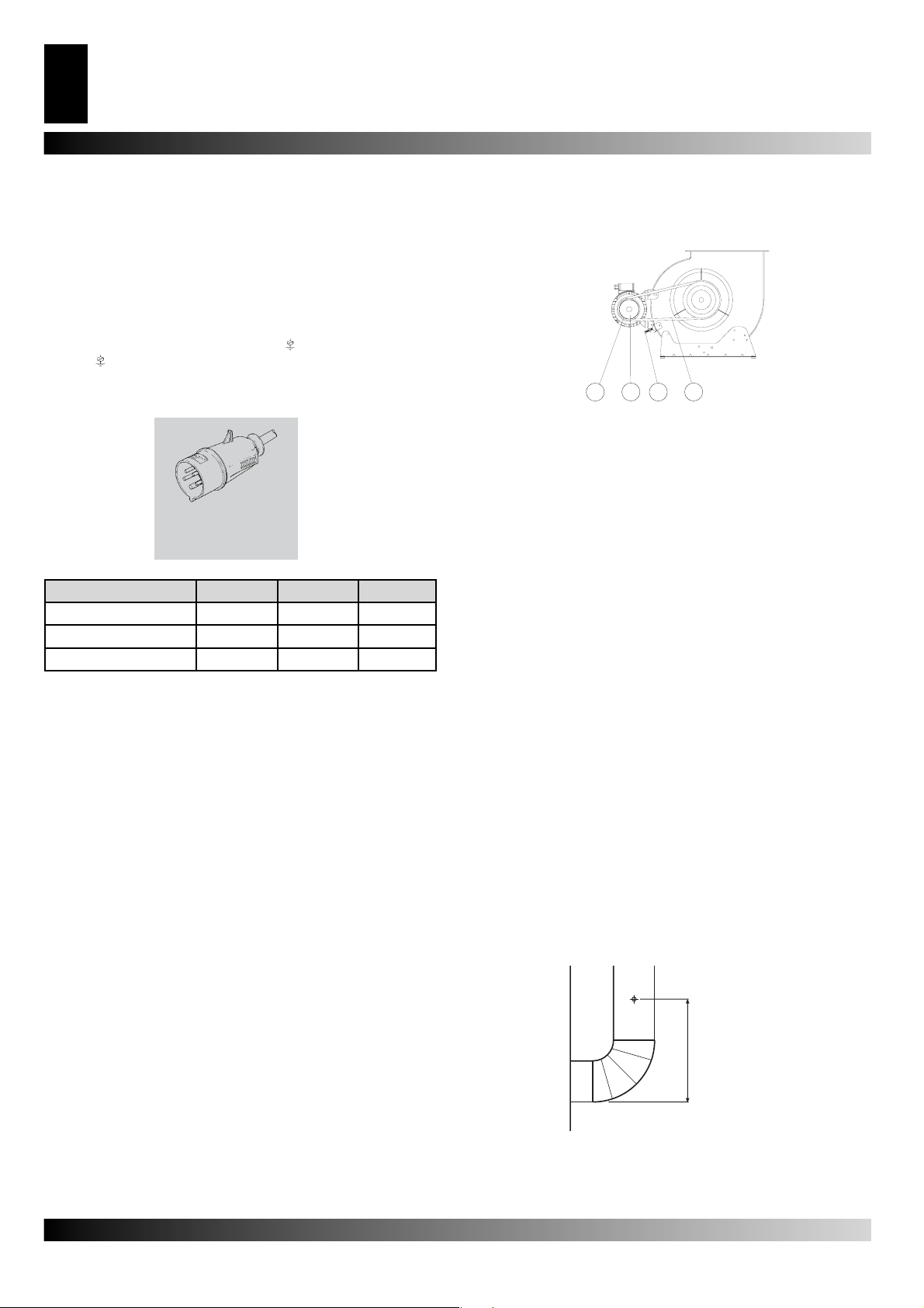
devono effettuare le seguenti operazioni (Fig. 3):
1) smontare ed estrarre la griglia di aspirazione del lato motore-
ventilatore;
2) svitare la vite (2) della slitta del motore;
3) togliere la cinghia (1);
4) allentare i grani (3);
5) ruotare la parte mobile (4) della puleggia svitandola o avvitan-
dola per diminuire o aumentare rispettivamente la velocità di
rotazione e, quindi, la portata d’aria del ventilatore;
6) bloccare i grani (3);
7) montare la griglia di aspirazione;
8) ripetere le operazioni da (1) a (7) sino a quando la portata
dell’aria non raggiunge il valore nominale.
COLLEGAMENTO AL CONDOTTO DI EVACUAZIONE DEI
FUMI
I condotti di evacuazione dei fumi devono essere in acciaio e
del tipo T250 conformi alla norma EN1443.
Il rendimento di combustione ed il corretto funzionamento del
bruciatore dipendono dal tiraggio del camino. Il collegamento
alla canna fumaria deve essere effettuato rispettando le disposizioni delle leggi vi-genti e osservando le seguenti prescrizioni:
• il percorso del raccordo fumario deve essere il più breve possibile e con pendenza ascendente;
• si devono evitare curve strette e riduzioni di sezione;
• deve essere predisposto un camino per ogni generatore di
aria calda;
• il tiraggio della canna fumaria deve essere almeno pari a quello prescritto
• la canna fumaria deve avere lunghezza pari ad 1 metro.
ANALISI DEI PRODOTTI DELLA COMBUSTIONE
Le sonde per il controllo della composizione dei prodotti della
combustione e della temperatura dei fumi devono essere posizionate come indicato in Fig. 4.
Fig. 4
Al termine delle prove di collaudo il foro praticato per l’inserimento delle sonde deve essere sigillato con materiale che
garantisca la tenuta del condotto e sia resistente alle elevate
temperature.
Page 5
GENERATORE D’ARIA CALDA
5
IT
COLLEGAMENTO ALLA LINEA DI ALIMENTAZIONE DEL
COMBUSTIBILE E TRASFORMAZIONE DA UN TIPO DI GAS
AD UN ALTRO
Tale collegamento deve essere eseguito secondo le indicazioni
del manuale d’uso del bruciatore.
Il bruciatore a gas é del tipo a policombustibile e, quindi, può
funzionare con gas metano o G.P.L.. Il generatore d’aria calda é
fornito con il bruciatore già predisposto per il funzionamento con
gas metano, G20. Per la trasformazione da gas metano a G.P.L.
o viceversa si devono seguire le istruzioni del manuale d’uso
del bruciatore. Tale manuale è allegato al presente con busta
contenente l’eventuale orifi zio calibrato da sostituire (manuale
d’uso del bruciatore) e un’etichetta adesiva riportante il tipo di
gas per il quale la macchina è stata predisposta.
ISTRUZIONI PER
L’UTILIZZAZIONE
AVVIAMENTO
Per avviare il generatore:
• Assicurarsi che il commutatore (1) sia predisposto sulla posizione “0” .
• Alimentare elettricamente il generatore agendo sull’interruttore
di sezionamento posto sul quadro elettrico di alimentazione.
• Se il funzionamento è manuale, spostare il commutatore (2)
nella posizione : il bruciatore si avvia e dopo alcuni minuti di
preriscaldamento della camera di combustione si avvia anche
il ventilatore.
• Se il funzionamento è automatico, si deve regolare il valore desiderato della temperatura del termostato ambiente e spostare
il commutatore (2) nella posizione : il generatore si avvia e si
arresta automaticamente quando la temperatura dell’ambiente
è rispettivamente minore o maggiore del valore selezionato.
• Se dopo tali operazioni il generatore non funziona, si deve
consultare il paragrafo “INCONVENIENTI DI FUNZIONAMENTO, CAUSE E RIMEDI” e scoprire la causa del mancato
funzionamento.
ARRESTO
ATTENZIONE: Non si deve mai arrestare il funzionamento
del generatore disinserendo l’interruttore di sezionamento
del quadro di alimentazione. L’alimentazione elettrica deve
essere disinserita solo dopo l’arresto del ventilatore.
Per arrestare l’apparecchio bisogna agire sul commutatore (2),
spostandolo nella posizione “0”, se il funzionamento è manuale,
o sul termostato ambiente se il funzionamento è automatico. Il
bruciatore si arresta e il ventilatore continua a funzionare, avviandosi più volte, fi no al completo raffreddamento della camera
di combustione.
di escludere la linea elettrica di alimentazione del generatore
prima di iniziare.
Prima di iniziare l’ operazione si deve:
• Arrestare la macchina secondo le indicazioni del paragrafo precedente,
• Disinserire l’alimentazione elettrica agendo sull’interruttore
di sezionamento posto sul quadro elettrico di alimentazione
• Attendere che il generatore si raffreddi.
PULIZIA DELLO SCAMBIATORE DI CALORE E DELLA CAMERA DI COMBUSTIONE
Per mantenere elevata l’effi cienza e prolungare la durata della
macchina, l’operazione descritta in questo paragrafo deve essere effettuata almeno una volta al termine della stagione di
esercizio o più frequentemente se vi è un’eccessiva quantità di
fuliggine; la presenza di quest’ultima può dipendere dal difettoso
tiraggio del camino, dalla pessima qualità del combustibile, dalla
cattiva regolazione del bruciatore o dall’alternarsi più o meno
frequente delle fasi di accensione ed arresto del bruciatore. È
opportuno prestare attenzione durante il funzionamento: pulsazioni all’avviamento possono essere dovute ad eccessiva
presenza di fuliggine.
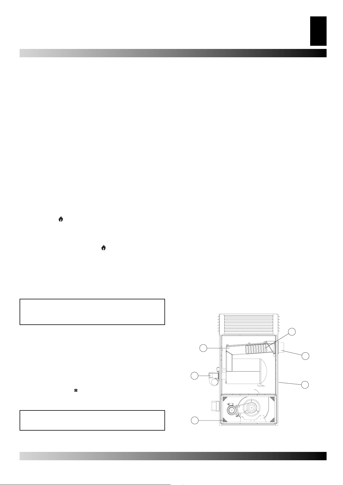
Per accedere alla parte interna dello scambiatore (1), dopo aver
rimosso il bruciatore (2), si deve smontare il pannello posteriore
superiore (3) e quello d’ispezione dello scambiatore (4) estraendo i turbolenziatori (5): con uno scovolo o un’aspirapolvere si
asportano la fuliggine residua e le parti estranee.
PULIZIA DEL VENTILATORE
Si devono asportare eventuali corpi estranei intrappolati fra le
maglie della griglia di aspirazione (6) e, se necessario, si deve
pulire la ventola con utensili per soffi are aria compressa.
PULIZIA DEL BRUCIATORE
Per il buon funzionamento del generatore si deve eseguire periodicamente la manutenzione del bruciatore rivolgendosi ad un
centro autorizzato di assistenza tecnica.
Le operazioni di pulizia, manutenzione e regolazione devono
comunque essere svolte attenendosi scrupolosamente alle specifi che istruzioni riportate sul manuale d’uso.
5
1
4
VENTILAZIONE
Per ottenere il funzionamento del generatore nel modo di sola
ventilazione continua, si deve spostare il commutatore (2) nella
posizione con simbolo .
MANUTENZIONE
ATTENZIONE: Tutte le operazioni descritte in questo
paragrafo devono essere eseguite solo da personale professionalmente qualifi cato.
Per il regolare funzionamento dell’apparecchio è necessario
effettuare periodicamente le seguenti operazioni, avendo cura
2
3
6
Fig. 5
Page 6

GENERATORE D’ARIA CALDA
6
IT
TRASPORTO E
MOVIMENTAZIONE
Per il trasporto e la movimentazione la macchina deve essere
adagiata su una pedana e sollevata con un carrello elevatore.
Prima di spostare l’apparecchio si deve:
Prima di spostare l’apparecchio si deve:
• Arrestare la macchina secondo le indicazioni del paragrafo “ARRESTO”
• Disinserire l’alimentazione elettrica agendo sull’interruttore
di sezionamento posto sul quadro elettrico di alimentazione
•Attendere che il generatore si raffreddi.
• Non tentare mai il sollevamento manuale del generatore: il
peso eccessivo potrebbe produrre danni fi sici rilevanti.
INCONVENIENTI DI FUNZIONAMENTO
Guasto Causa Rimedio
L’apparecchio non parte 1.Alimentazione elettrica mancante
2.Posizione errata dell’interruttore generale
3.Funzionamento irregolare del termostato ambiente
4.Dispositivo di sicurezza (bruciatore, termostato
L) non riarmato dopo una riparazione
Intervento del termostato L 1.Surriscaldamento della camera di combustione 1.Controllare la portata di combustibile
Intervento del relé termico RM
(la lampada (9) si illumina)
Il bruciatore si avvia, la
fi amma non si accende e la
spia del pulsante di riarmo si
illumina
Il ventilatore non si avvia o si
avvia in ritardo
Rumorosità o vibrazioni del
ventilatore
Riscaldamento insuffi ciente 1.Capacità insuffi ciente del bruciatore 1.Rivolgersi al Servizio di Assistenza Tecnica
1. Eccessivo assorbimento di corrente del motore
del ventilatore
1.Funzionamento irregolare del bruciatore 1.Se dopo aver premuto il pulsante di riarmo e
1.Alimentazione elettrica mancante
2.Guasto del termostato F
3.Avvolgimento del motore bruciato o interrotto
4.Condensatore del motore bruciato
5.Cuscinetti del motore bloccati
1.Corpi estranei depositati sulle pale del ventilatore
2.Scarsa circolazione di aria
3. Cinghia di trasmissione allentata o non allinea-
ta
1.Verifi care la funzionalità e la posizione dell’
interruttore
1.Verifi care le caratteristiche della linea elettrica
1. Verifi care i collegamenti elettrici
1. Controllare l’integrità dei fusibili
2.Selezionare la posizione corretta
3.Verifi care che la posizione del T.A.sia corretta
3. Verifi care la funzionalità del termostato
4. Premere il rispettivo pulsante di riarmo
1.Verifi care la corretta posizione di eventuali
serrande, bocchette, etc.
1.Rimuovere eventuali parti intrappolate nei
condotti dell’aria o nelle griglie di ventilazione
1. Aumentare la portata d’aria variando il rappor-
to di trasmissione tra motore e ventilatore
1. Regolare il rapporto di trasmissione tra il mo-
tore e il ventilatore
aver avviato il generatore l’inconveniente si ripete per la seconda volta, rivolgersi al Servizio
di Assistenza Tecnica
1.Controllare l’integrità dei fusibili
1.Verifi care i collegamenti elettrici
2.Controllare il termostato, regolarlo ed eventualmente sostituirlo
3.Sostituire il motore del ventilatore
4.Sostituire il condensatore
5.Sostituire i cuscinetti
1.Asportare le parti estranee
2.Eliminare ogni possibile ostacolo al passaggio
dell’aria.
3. Regolare la tensione della cinghia di trasmissione
Page 7

HOT AIR GENERATOR
7
GB
DESCRIPTION
Warning: During use, two of the four sides must be left open
so as to avoid overheating of the combustion chamber.
BG space heaters have been designed for use in small to me-
dium-sized rooms and buildings where a fi xed heating system
is required.
Heat is produced by combustion and the heat from the smoke is
transmitted to the fresh air through the metal walls of the combustion chamber and the heat exchanger. Smoke circulates twice
in this type of combustion chamber.
Air and smoke pass through separated ducts, both of which are
welded and sealed. When, after combustion, the waste gases
have cooled down, they are expelled through a duct which must
be connected to a chimney or chimney fl ue. The chimney or
chimney fl ue must be big enough to guarantee that the smoke
is expelled effi ciently .
The air which is used in combustion is aspirated directly from the
room or building which is being heated. It is therefore of utmost
importance that the room or building is properly ventilated to
guarantee the continual circulation of enough fresh air.
The air head has four lateral openings and adjustable fi ns which
send the hot air in the desired direction (Fig. 1).
Fig. 1
BG heaters can operate with burners thatare fuelled by heating
oil, methane (G20) or LPG (butane G30 andpropane G31) of the
ON-OFF type.
There are three safety devices which are activated in case of serious malfunction. The Burner Control Device, which is mounted
on the burner and has a restart button, automatically stops the
burner if the fl ame goes out. The Overheat Thermostat, L, of the
manual restart type, is activated if the temperature of the combustion chamber rises above the set maximum limit; the warning
light (9) lights up and the heater stops working. The Thermal
Relay , RM, is activated if the fan motor starts using more electric
current than the maximum permitted limit; the warning light (10)
lights up and the heater stops working.
If any of these safety devices are activated you should check
carefully what the problem actually is before pressing the restart
button and starting the heater up again (“OBSERVED FAULTS,
CAUSES AND REMEDIES”).
• Infl ammable material should be kept at a safe distance from
the heater (Minimum 3 meters).
• All fi re prevention regulations must be adhered to.
• The room or building that is being heated must be suffi ciently
ventilated so that the heater has enough air to function properly.
• The heater must be near a chimney or chimney fl ue and a sui-
table electric switchboard.
• Don’t let animals or children near the heater.
• After use make sure the disconnecting switch is off.
When using any type of space heater it is obligatory:
• not to exceed the maximum level of heat output of the furnace.
• to make sure that there is adequate air circulation and air supply to the heater and that nothing is obstructing the aspiration
and expulsion of air. Movement of air may be obstructed in
various ways including placing covers or other objects on the
heater or positioning the heater too near a wall or other large
object. If there is insuffi cient air supply the combustion cham-
ber overheats and the overheat thermostat with manual restart
is activated.
INSTALLATION
Warning: Qualifi ed personnel must carry out the following
operations.
REMOVAL OF THE PALLET
To remove the space heater from the pallet on which it is attached for the transport, unscrew the fi xing screw of the inferior
panel and lift the machine with a suitable mean of lifting using
the four points (a) (Fig. 2).
a
a
a
a
Fig. 2
GENERAL ADVICES
Warning: Only the burners which are chosen and supplied by the manufacturer can be used. If another type of
burner is used the heater will no longer comply with CE
regulations.
The space heater must be installed, set up and used in accordance with existing laws.
Here are a few general guidelines which should be followed:
•Follow the instructions in this booklet very carefully.
•Don’t install the heater in places where there may be a risk of
fi re or explosion.
ELECTRICAL CONNECTIONS AND SETTINGS
Warning The mains supply to the heater must be earthed
and have a magneto-thermal switch with differential.
The power cord must be connected to a switchboard thath as a disconnecting switch.
Every space heater is supplied along with the safety and control
devices which are indispensable to the correct functioning of the
unit.
The electric switch board, the fan thermostat and the overheat
thermostat with manual restart have already been connected.
The following operations must now be carried out:
Page 8
HOT AIR GENERATOR
1
4
3
2
200 mm
8
GB
• Table I shows the adhesive label on units which have three-phase
supply. Connect to the electricity supply having read the adhesive
label that details electricity supply characteristics (See T able II).
The power cord, which is not supplied with the heater:•must be
of the HO7RN-F type (section 1, 5 mm²)
• must be connected to the unit electric switchboard by means of
the cable fastener (3) and connected to the terminals N, L and
,if single-phase supply , or to the terminals N, R, S, T and ,
if three-phase supply (“WIRING DIAGRAM”).
• must be connected directly to a mains switchboard that has a
disconnecting switch.
• must not be longer than 2 meters.
• The burner must be mounted and attached to the heather
with appropriate screws. The gaskets supplied with the burner
should be placed between the burner and the heater.
• The burner must be connected to the fuel supply and the
burners calibration (“burner Instruction manual”) unanimously
with themaximun space heater power signed on the technical
label.
• Connect accessories such as the room thermostat or clock to
the unit electric switchboard: electric wire must be connected
by means of the cable fastener (8) to the terminals 7 and 8.
❏ 230V - 3 ~ - 50Hz
❏ 400V - 3 ~ - 50Hz
BG 100 BG 150 BG 200
Number of phases 3 3 3
Tension 230/400 230/400 230/400
Frequency 50 50 50
Having completed all these operations check carefully that all
electrical connections correspond to the wiring diagram and
check the setting of thermostat F (“TECHNICAL SPECIFICATIONS”). When the heateris fi rst turned on you must check that
the fan does not use more electricity than the maximum permitted limit. Finally, follow the instructions in the Burner Instruction
Manual to regulate the burner unanimously to the suitable technical data for the space heater.
[V]
[Hz]
Tab. 2
Tab. 1
Fig. 3
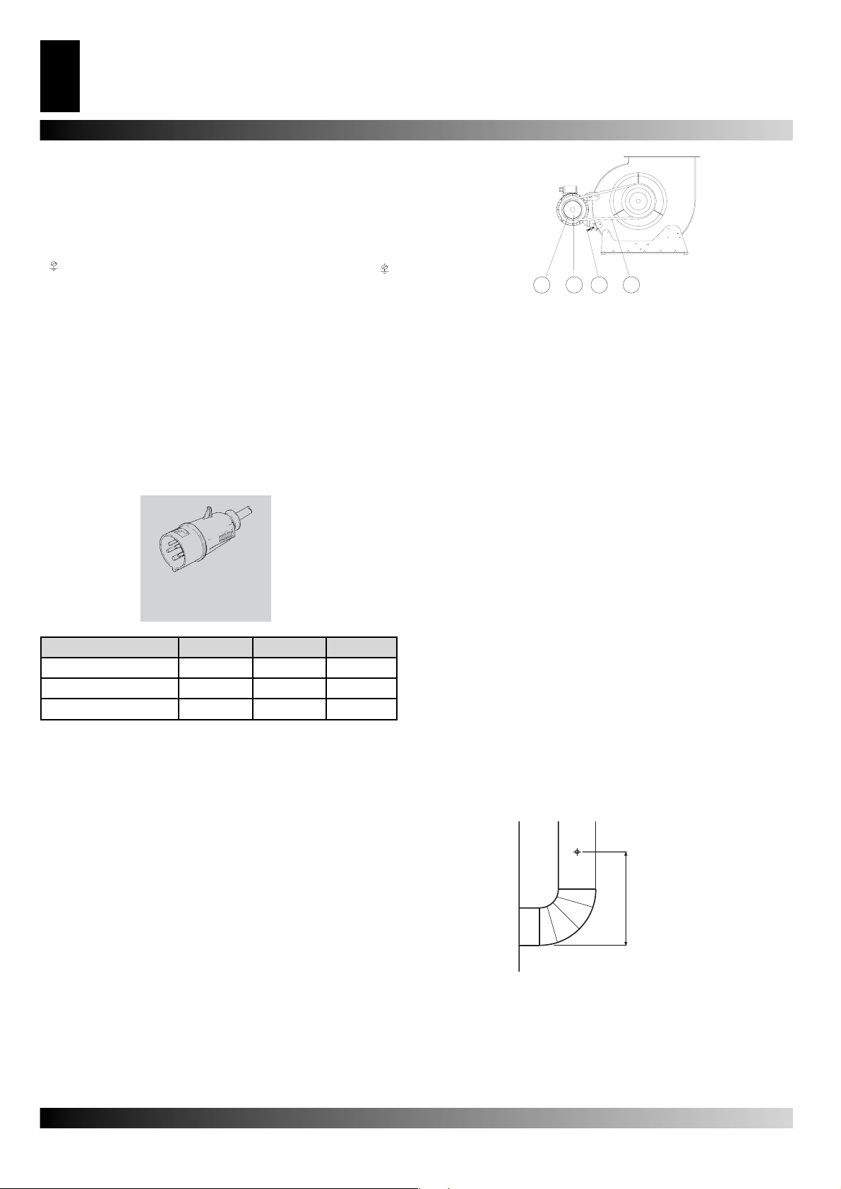
1) Remove the aspiration grill which is on fan motor side of
theunit.
2) Remove the screws (2) from the motor slide.
3) Remove the belt (1).
4) Loosen the bolts (3).
5) Turn the pulley clockwise and anti-clockwise in order to increase or reduce the volume of air.
6) Tighten the bolts (3).
7) Put back the aspiration grill.
8) Repeat operations 1-7 until the correct volume of airfl ow ha-
sbeen achieved.
DRAFT
The evacuation smoke fl ues have to be in steel and of the kind
T250, conforming to the norm EN 1443.
Effi cient combustion and trouble-free working of the burner de-
pend on effi cient fl ue draft. The unit must be connected to the
chimney fl ue in accordance with current legal regulations and in
line with the following guidelines:
• The tube that carries the smoke should cover as short a distan-
ce as possible and should slant upwards
• There should be no sharp bends in the tubes and the diameter
of the tubes must never be reduced
• Every heater must have its own chimney
• Flue draft must at least correspond to the minimum compulsory
level in the Technical Specifi cations
• the chimney fl ue has to have a length of 1 meter.
ANALYSIS OF COMBUSTION WASTE PRODUCTS
The probes which check the composition of combustion waste
products and smoke temperature must be positioned as indicated in Fig. 4.
When these tests have been completed the hole that was drilled
for the probe must be sealed with a material which is resistant
to high temperatures and which ensures that the tube remains
airtight.
CONNECTION TO HOT AIR DUCTS
The space heater provides heat by releasing and dispersing hot
air (Fig.1). An airhead is supplied and it can be connected to new
air ducts if the user wishes to satisfy specifi c needs. In this case
and in particular if the diameter and length of the ducts have
been changed or if the number of bends has been modifi ed, air
output may vary. Consequently it is very important to check and
regulate air output when any modifi cation is made to airheads or
air ducts. In all circumstances you must ensure that (Fig. 3):
• The fan does not use more electricity than the maximum permitted limit.
• The volume of air fl ow corresponds to the recommended le-
vel.
If the volume of fl ow rate air differs from preset values proceed
as follows:
Fig. 4
CONNECTION TO FUEL SUPPLY AND CHANGING
FROM ONE TYPE OFGAS TO ANOTHER
To connect the burner to the fuel supply, follow the instructions
in the Burner Instruction Manual
The burner can use both methane gas and LPG. This heater has
been predisposed to use methane gas, G20. To change from
methane gas to LPG or vice versa consult the Burner Instruction Manual which accompanies this manual. With the Burner
Page 9

WARMLUFTERHITZER
9
DE
Instruction Manual there is an envelope, which contains a spare
choke and an adhesive label that indicates the type of gas that
the burner should use.
INSTRUCTIONS FOR USE
SWITCHING ON
• Set the control knob (2) to position “0”.
• Turn on the disconnecting switch on the electric switchboard.
• If the unit is operated manually turn the control knob to .The
burner starts up, the combustion chamber heats up and then
the fan starts.
• If the unit operates automatically set the room thermostat to the
desired level and turn the control knob (2) to : the heater will
now start and stop automatically.
• If the heater doesn’t start after you have completed the above
operations consult the Troubleshooting section of this manual.
TURNING OFF
WarningNever stop the heater by simply turning off the
disconnecting switch on the electric switchboard. The
electrical supply must only be disconnected when the fan
has come to a complete stop.
In manual operation turn control knob (2) to “0” or turn off control
in automatic operation.
The burner stops while the fan turns itself on and off until the
combustion chamber has completely cooled down.
VENTILATION
When the control knob is turned to the symbol the heater
operates in continuous fan mode.
MAINTENANCE
Warning: Qualifi ed personnel must carry out the following
operations.
Warning: Before carrying out any maintenance operation
the heater must be disconnected from the mains. Therefore:
• Stop the machine as instructed above
• Turn off the disconnecting switch on the electric
switchboard.
• Wait until the heater has cooled down.
CLEANING THE BURNER
For the heater to work effi ciently the burner must be serviced re-
gularly by an Authorized Service Technician. All cleaning, servicing and regulation operations must be carried out as indicated
in the Burner Instruction Manual.
5
1
4
2
3
6
Fig. 5
TRANSPORTING AND MOVING THE HEATER
T o move or transport the heater, place it on a raised base and lift
with by a forklift truck.
Warning: Before moving the unit:
• Turn it off as indicated above.
• Disconnect electricity by pulling out the plug.
• Wait until the heater cools down
• Never try to lift the heater manually. Doing so could result
in physical injury.
CLEANING THE HEAT EXCHANGER AND THE COMBUSTION CHAMBER
For the heater to operate effi ciently the heat exchanger and
combustion chamber must be cleaned after a period of prolonged use and more frequently if too much soot builds up. Soot
builds up when there is not enough chimney draft, when the fuel
is of very poor quality, when the burner is regulated incorrectly
or when the heater is switched on and off too frequently. If the
heater starts vibrating when it is turned on there is probably too
much soot.
To get at the internal parts of the heat exchanger (1), remove
the burner (2), take off the upper back panel (3), the exchanger
inspection panels (4) and the baffl e plates (5). Clean out soot or
extraneous material with a vacuum cleaner or tube cleaner.
CLEANING THE FAN
Remove any dirt or extraneous material from the mesh of the
aspiration grill (6) and if necessary clean the propeller with an
air-suction tool.
Page 10

HOT AIR GENERATOR
10
GB
TROUBLESHOOTING
Problem Cause Remedy
The heater won’t start 1.Faulty electrical supply
2.Wrong positioning of main switch
3.Wrong setting of room thermostat
4.Safety device (burner, thermostat L) not
restarted after repairs
Thermostat L cuts in 1.The combustion chamber has overheated 1. Check fuel fl ow
Thermal relay RM cuts in (warning
light (9) lights up)
The burner starts up, the fl ame
doesn’t light up and the restart
light comes on
The fan doesn’t start up or starts
up late.
The fan vibrates or makes
unusual noise
Not enough heat 1.Wrong burner 1. Call an Authorized Service Technician
1. Fan current absorption is excessive 1. Adjust transmission between motor and fan
1.Burner not working correctly 1. Press the restart button to turn on the heater. If
1.No electrical power
2.F thermostat out of order
3.Winding of motor burnt or interrupted
4.Condenser burnt
5.Motor bearings blocked
1. Extraneous material on fan blades
2. Not enough air circulation
3. Drive belt loose or not aligned
1. Check function and positioning of main switch
1. Check power cord
1. Check electrical connections
1. Check fuses
2. Put main switch in correct position
3. Check setting of room thermostat
3. Check function of room thermo-stat
4. Press the appropriate restart button
1. Check position registers, draw-holes, etc.
1. Remove extraneous material from air ducts and
ventilation grills
1. Increase air fl ow adjustining transmission
1. Between motor and fan
the same problem arises again call an Authorized
Service Technician
1. Check fuses
1. Check electrical connections
2. Check the thermostat, set it and replace it if
necessary
3. Replace the fan motor
4. Replace the condenser
5. Replace the bearings
1. Remove extraneous material
2. Remove obstacles to air circulation
3. Adjust drive belt tension
Page 11

WARMLUFTERHITZER
11
DE
BESCHREIBUNG
Achtung: Während des Betriebs müssen zwei der vier
Seiten offen gelassen werden, um ein Überhitzen der
Brennkammer zu vermeiden.
Die Warmlufterzeuger der Serie BG sind zum Heizen von mittleren bis zu großen Räumen bestimmt, für die eine standfeste
Heizquelle erforderlich ist.
Die Luft wird dadurch erwärmt, dass die mittels Verbrennung
erhaltene thermische Energie durch den heißen Rauch über die
Metallfl ächen der Brennkammer, mit doppeltem Rauchumlauf,
sowie über den Wärmeaustauscher an die frische Luft abgegeben wird.
Der für die Passage der Luft und jener für den Durchzug des
Rauchs vorgesehene Kanal sind voneinander getrennt und so
ausgeführt, dass die Schweißstellen und die Dichtungen hermetisch sind. Die Verbrennungsprodukte werden nach dem Abkühlen einem Abzugsrohr zugeführt; das oben genannte Rohr ist
an einen Kamin bzw. Schornsteinrohr anzuschließen und zwar
sollen die Ausmaße desselben so sein, dass der Austritt des
Rauches gewährleistet wird.
Der Sauerstoffträger, d.h. die für die Verbrennung notwenige
Luft, wird vom Brenner direkt aus dem aufzuheizenden Raum
angesaugt; der oben genannte Raum muss deshalb entsprechend gelüftet werden, damit ein hinreichender Luftaustausch
vorhanden ist.
Der Endausblaskanal für die Warmluft ist mit vier seitlichen regelbaren Öffnungen versehen (Bild 1), die so gedreht werden
können, dass der Warmluftstrom in die gewünschte Richtung
ausgeblasen wird.
Bild 1
Die Warmlufterzeuger BF können mit Dieselöl, Erdgas (G20)
oder Flüssiggas GPL (Butan, G30, und Propan-gas, G31) bei
betriebenen Brennern auf Betriebsweise ON-OFF verwendet
werden.
Der Betrieb des Brenners wird schließlich durch drei Sicherheitsvorrichtungen überprüft, die im Falle einer schweren Betriebsstörung eingreifen. Das Brenner-Kontrollgerät, das auf dem
Gehäuse des Brenners selbst montiert ist und über eine Wiedereinschalttaste verfügt, bewirkt bei Erlöschen der Flamme den
Stillstand. Der Sicherheitsthermostat mit Wiedereinschaltung
von Hand L und mit dem thermischen Relais RM greifen ein,
indem sie den Betrieb des Warmlufterzeugers blockieren: Erstgenannter, wenn die Brennkammertemperatur den eingestellten Grenzwert überschreitet (die Signalllampe (9) leuchtet auf),
Zweitgenannter, wenn der Strombedarf des Lüftermotors den
Grenzwert überschreitet (die Signalllampe (10) leuchtet auf).
Wenn eine dieser Sicherheitsvorrichtungen eingreift, ist stets die
Ursache dafür aufzusuchen und der Schaden muss vor Drücken
der entsprechenden Wiedereinschalttaste und Wiedereinschalten des Warmlufterzeugers behoben werden (“BETRIEBSSTÖRUNGEN, URSACHEN UND BEHEBUNGEN”).
ALLGEMEINE EMPFEHLUNGEN
Achtung: Es dürfen lediglich die vom Hersteller ausgewählten und gelieferten Brenner eingesetzt werden. Die
EG-Kennzeichnung am Gerät ist hinfällig, falls der Brenner
mit einem nicht originalen Brenner ersetzt wird, auch wenn
dieser über ähnliche Merkmale verfügen sollte.
Die Installation, die Regelung und der Einsatz von Warmlufterzeugern hat unter Berücksichtigung der geltenden Vorschriften
und Gesetze über die Verwendung des Gerätes zu erfolgen.
Es empfi ehlt sich, für Folgendes zu sorgen:
• Genaue Befolgung der in vorliegendem Handbuch enthaltenenAnleitungen;
• Vermeidung der Aufstellung von Warmlufterzeugern in Räumen, in welchen Explosionsgefahr besteht oder in denen kein
Feuer verwendet werden darf;
• Keine Lagerung von entfl ammbaren Materialien in der Nähe
des Gerätes (Mindestabstand entspricht 3 m);
• Entsprechende Vorsorge für brandverhütende Massnahmen;
• Lüftung des Raumes, in dem sich der Warmlufterzeuger befi ndet.
Diese soll außerdem für den Bedarf des Gerätes selbst hinreichend sein;
• Aufstellung des Gerätes in der Nähe eines Kamins und eines
elektrischen Versorgungsschaltpults, das den angeführten
Kennwerten entspricht;
• Überprüfung des Gerätes vor der Inbetriebnahme und regelmäßige Kontrolle während der Verwendung selbst, insbesondere soll verhindert werden, dass sich dem unbewachten Gerät
Kinder oder Tiere nähern;
• Nach Abstellen des Betriebes soll jedesmal der Unterbrechungsschalter aus der Steckdose herausgezogen werden.
Weiters sind die Betriebsbedingungen des Warmlufterzeugers
zu berücksichtigen, insbesondere:
• die thermische Höchstleistung der Feuerung darf nicht überschritten werden;
• Man hat sich zu vergewissern, dass die Luftzufuhr nicht unter
der Nennluftzufuhr liegt; es ist deshalb zu prüfen, dass keine
Hindernisse oder Verstopfungen in den Ansaug- und/oder Ausblasrohren vorhanden sind, wie zum Beispiel auf dem Gerät
abgelegte Tücher oder Decken oder in unmittelbarer Nähe des
Gerätes befi ndliche Wände bzw. große Gegenstände. Eine
geringe Luftzufuhr kann nämlich zu einer Überbelastung des
Lüfters führen, was eine Überhitzung des Motors und der Brennkammer bewirkt und demnach das Einschalten der Sicherheitsthermostaten, mit Wiedereinschaltung von Hand.
ANLEITUNGEN FÜR DEN INSTALLATEUR
Achtung: Alle in diesem Kapitel beschriebenen Operationen sind von diesbezüglich befugtem Fachpersonal
auszuführen.
ENTFERNUNG DER TRANSPORT PALETTE
Die Befestigungschrauben zwischen Palette und Heizer entfernen und mit Heber den Heizer entfernen. Zur Befestigung am
Heber benüzt man die vier Schraubenstellen (a) (Bild 2).
Page 12

12
1
4
3
2
DE
WARMLUFTERHITZER
a
a
a
a
Bild 2
STROMANSCHLÜSSE UND REGELUNGEN
AchtungDie elektrische Versorgungsleitung des Warmlufterzeugers muss mit einer Erdleitung und mit einem thermischen Magnetschalter mit Differential ausgestattet werden.
Die Serienausführung des Warmlufterzeugers versteht sich
inklusive aller für den Betrieb des Gerätes unerläßlichen Kontroll- und Sicherheitseinrichtungen: elektrische Schalttafel, Lüfterthermostat und Sicherheitsthermostat mit Wiedereinschaltung
von Hand bereits angeschlossen.
Das elektrische Versorgungskabel ist an ein mit Trennschalter
ausgestattetes, elektrisches Schaltpult anzuschließen.
Weiters ist noch folgendes auszuführen:
• Der Anschluss ans Stromnetz, nach vorheriger Überprüfung der
auf dem Klebeschild angeführten elektrischen Versorgungswerte
(in der Tabelle I ist das auf den Geräten mit dreiphasiger Versorgung angebrachte Etikett zu ersehen, in der Tabelle II wird die
Versorgungsart angegeben); beim Versorgungskabel, das nicht
serienmäßig mitgeliefert wird, ist Folgendes zu beachten:
• HO7RN-F-Kabel mit einem Kabelschnitt von 1,5 mm²
• es wird mittels der Kabelführung (3) in die Schalttafel des Warmlufterzeugers eingeführt und an die Klemmen N, L und ,
einphasige Versorgung, bzw. an die Klemmen N, R, S, T und
,dreiphasige Versorgung (“ELEKTRISCHES SCHEMA”),
• es wird direkt an eine mit Trennschalter versehene Versorgungs-schalttafel angeschlossen,
• seine Länge darf den Wert von 2 m nicht überschreiten;
• Anschluss des Brenners an die Brennstoff-Versorgungsleitung
und das Tarierung des Brenners (Brenner-Betriebsanleitung)üb
ereinstimmed zur maxime thermische des Erzeugers zeigt auf
das Etikett der technischen Daten;
• Eventueller Anschluss der Raumthermostaten oder weiterer
Zubehörteile der Anlage (so z.B. einer Uhr): das Kabel mittels
der Kabelführung (8) in die Schalttafel des Warmlufterzeugers
einführen und an die Klemmen 7 und 8 der Klemmenleiste angeschließen (“ELEKTRISCHES SCHEMA”).
Nachdem alle Anschlüsse vorgenommen worden sind, ist es
ratsam, vor Inbetriebnahme des Gerätes die hergestellten Anschlüsse mit denjenigen, die auf dem elektrischen Schema verzeichnet sind, zu vergleichen und die Eichung des Thermostats
F (“T ABELLE DER TECHNISCHEN DATEN”) zu überprüfen. Bei
der ersten Inbetriebnahme ist stets darauf zu achten, dass der
Strombedarf des Lüfters die angegebenen Werte nicht überschreitet.
Der Brenner ist abschließend gemäß den in der beigefügten
Bedienungsanleitung vermerkten Angaben zu regeln übereinstimmend zu den technischen Daten geeigneten fün den Warmlufterzeuger.
ANSCHLUSS AN DIE WARMLUFT-FÖRDERKANÄLE
Der Warmlufterzeuger ist für einen Betrieb mit direkter Luftverteilung vorgesehen (Bild 1).
Diese Vorrrichtung kann an Kanäle mit entsprechendem Durchmesser angeschlossen werden, falls spezielle Einsatzfälle dies
verlangen; da der Wert der Luftförderung variieren kann, sind
Kontrollen und Regelungen jedesmal durchzuführen, wenn wesentliche Veränderungenam Verteilungskreislauf der Warmluft
auftreten (Veränderung der Länge oder des Durchmessers der
Rohre, der Anzahl der Kurven usw.).
Demnach ist folgendes vorzunehmen:
• Sicherstellen, dass der vom Lüftermotor aufgenommene Strom
nicht über dem angegebenen Wert liegt;
• Sicherstellen, dass die Luftförderleistung der Nennförderleistungentspricht.
Falls der Luft-Ausblaswert sich von dem angegebenen Wert
unterscheidet, geht man wie folgt vor (Bild 3):
❏ 230V - 3 ~ - 50Hz
❏ 400V - 3 ~ - 50Hz
BG 100 BG 150 BG 200
Phasenanzahl 3 3 3
Spannung 230/400 230/400 230/400
Frequenz 50 50 50
• Brennermontage, wobei der Brenner an den Warmlufterzeuger
mit den entsprechenden Schrauben zu montieren ist, wobei die
mit dem Brenner mitgelieferte Dichtung zwischenzulegen ist;
[V]
[Hz]
Tab. 2
Tab. 1
Bild 3
1) das auf der Motor-Lüfterseite befi ndliche Ansauggitter abmon-
tieren und herausnehmen;
2) die Schraube des Motorschlittens herausschrauben;
3) den Riemen (1) entfernen;
4) die Stifte lockern
5) den beweglichen Teil (4) der Scheibe durch Herausschrauben
bzw. Festschrauben drehen, um die Rotationsgeschwindigkeit
zu verlangsamen oder zu beschleunigen und somit den Luftaustritt beim Lüfter zu regulieren;
6) die Stifte (3) festschrauben;
7) das Ansauggitter montieren;
8) der Reihe nach die Operationen von (1) bis (7) solange wiederholen, bis die Luft den Nennwert erreicht hat.
ANSCHLUSS AN DAS RAUCHROHR ZUR ENTFERNUNG DES RAUCHES
Die Rauchleitungen von Evakuieren müssen in Stahl und von tpy
Page 13

WARMLUFTERHITZER
13
DE
T250, Normentsprechend EN 1443 sein.
Die Brennerleistung und der einwandfreie Betriebsablauf des
Brenners hängen vom Schornsteinzug ab. Der Schornsteinanschluss hat entsprechend der in Kraft stehenden gesetzlichen
Normen und unter Beachtung folgender Vorschriften zu erfolgen:
• Der Rauchrohrweg hat so kurz wie möglich zu sein und aufsteigende Richtung aufzuweisen;
• Enge Kurven und Durchmesserverringerungen sind zu vermeiden;
• Für jeden einzelnen Warmlufterzeuger ist ein Schornstein vorzusehen;
• Der Schornsteinzug soll mindestens dem vorgeschriebenen
entsprechen
• der Schornstein muß 1 Meter Länge zu haben.
ANALYSE DER VERBRENNUNGSPRODUKTE
Zur Kontrolle der Zusammensetzung der Verbrennungsprodukte
und der Rauchtemperatur sind die entsprechenden Sonden, wie
auf Bild 4 dargestellt, anzubringen.
Bei Abschluss der Prüfung ist das zur Einführung der Sonden her
gestellte Loch mit einem Material zu versiegeln, das die Dichtheit
des Rohres gewährleistet und bei hohen Temperaturen temperaturbeständig bleibt.
200 mm
Bild 4
ANSCHLUSS AN DIE BRENNSTOFFVERSORGUNGSLINIE UND UMRÜSTUNG DES GASGERÄTS FÜR
EINE ANDERE GASART
Dieser Anschluss hat gemäß den Brenneranleitungen zu erfolgen. Der Gasbrenner wird als Mehrbrennstoff-Ausführung hergestellt und kann daher mit Erdgas oder Flüssiggas GPL betrieben
werden. Der Warmlufterzeuger verfügt über einen Brenner, der
bereits zum Betrieb mit Erdgas, G20, vorgesehen ist. Zum Umrüsten vom Erdgasbetrieb auf Flüssiggasbetrieb, oder umgekehrt,
sind die Anleitungen des Brennerhandbuchs zu befolgen. Das
oben gennante Hanbuch wird mit dem vorliegenden mitgeliefert.
Anliegend befi ndet sich auch ein Umschlag mit dem kalibrierten
Mundstück, das eventuell auszuwechseln ist (“BRENNER-GEBRAUCHSANLEITUNGEN”) und ein Aufkleber, auf dem die
Gasart, für die das Gerät vorgesehen ist, angegeben ist.
GEBRAUCHSANWEISUNGEN
INBETRIEBNAHME
Beim Anlassen des Warmlufterzeugers ist Folgendes zu beachten:
• Sich vergewissern, dass der Geräteschalter (2) auf Schaltstellung “0” gestellt ist.
• Den Warmlufterzeuger durch Drücken auf dem am elektrischen
Versorgungsschaltpult angebrachten Unterbrechungsschalter
elektrisch versorgen.
• Bei nicht automatischem Betrieb den Geräteschalter (2) auf
Position stellen: der Brenner startet und nach einer kurzen
Vorwärmung der Brennkammer (einigen Minuten) setzt sich
ebenfalls der Lüfter in Betrieb.
• Bei einem automatisch betriebenen Gerät ist der gewünschte
Temperaturwert auf dem Raumthermostat einzustellen und
der Geräteschalter (2) auf Position zu stellen: Das An- und
Abschalten des Gerätes erfolgt automatisch, sobald die Raumtemperatur unter bzw. über dem eingestellten Wert liegt.
• Sollte der Warmlufterzeuger nach genannten Vorkehrungen
nicht funktionieren, sehen Sie zur Auffi ndung der Störungsur-
sache in den Paragraphen “BETRIEBSSTÖRUNGEN, URSACHEN UND BEHEBUNGEN” nach.
ABSTELLEN
Achtung: Der Betrieb des Warmlufterzeugers darf nicht
dadurch gestoppt werden, dass man einfach den Stecker
aus dem Versorgungsschaltpult herauszieht. Die elektrische Versorgung darf erst nach Stillstand des Lüfters
unterbrochen werden.
Um das Gerät abzustellen, ist bei manuell betriebenem Gerät
der Geräteschalter (2) auf Position “0” zu stellen. Wenn es sich
um ein automatisch betriebenes Gerät handelt, erfolgt die Regelung am Raumthermostat. Der Brenner stoppt und der Lüfter
bleibt weiter in Betrieb, wobei er mehrmals anläuft, bis die Brennkammer völlig abgekühlt ist.
LÜFTUNG
Um lediglich den fortlaufenden Lüftungsbetrieb seitens des
Gerätes zu erwirken, ist der Geräteschalter (2) auf die Position
des -Symbols zu stellen.
WARTUNG
Achtung: Alle in diesem Kapitel beschriebenen Operationen sind von entsprechend befähigtem Fachpersonal
auszuführen.
Für einen tadellosen Betrieb des Gerätes sind regelmäßig folgende Maßnahmen zu treffen, wobei allerdings zu beachten ist,
dass vorher die Stromversorgung des Warmlufterzeugers zu
unterbrechen ist.
Achtung: Vor Beginn der Arbeiten ist Folgendes durchzuführen:
• Das Gerät gemäß den Anleitungen des vorherigen Abschnittes “ABSTELLEN”, anhalten.
• Die Stromversorgung durch Drücken auf dem auf demSchaltpult befi ndlichen Unterbrechungsschalter unterbin-
den und
• Solange warten, bis das Gerät abgekühlt ist.
REINIGUNG DES WÄRMEAUSTAUSCHERS UND DER
BRENNKAMMER
Um dem Gerät seine hohe Leistungsfähigkeit zu bewahren und
seine Lebensdauer zu verlängern, sind die in diesem Paragraphen beschriebenen Reinigungsarbeiten wenigstens ein Mal
am Ende jeder Betriebssaison vorzunehmen, oder mehrmals,
wenn eine übertriebene Menge an Ruß vorherrscht. Zu dieser
Erscheinung kann es kommen, wenn z.B. der Schornsteinzug
nicht einwandfrei ist, Brennstoff schlechter Qualität verwendet
wird, oder der Brenner schlecht eingestellt ist, oder weiters,
wenn das An- und Abschalten des Gerätes mehr oder weniger
oft erfolgt. In diesem Zusammenhang ist während des Betriebes
des Gerätes aufzupassen: kommt es zu Pulsierungen beim
Anlauf, kann dies bedeuten, dass eine zu große Rußmenge
vorhanden ist.
Um sich Zugang zum Inneren des Wärmeaustauschers (1) zu
verschaffen, sind nach Entfernung des Brenners (2) die hintere,
obere Platte (3), die Inspektionsplatten (4) des Wärmeaustauschers und der Verwirbelungsbleche (5) abzumontieren: mit
einer Reinigungsbürste oder einem Staubsauger, sind rückständiger Ruß und sonstige Fremdkörper zu entfernen.
Page 14

14
14
DE
WARMLUFTERHITZER
REINIGUNG DES LÜFTERS
Eventuell auf dem Gitter an der Ansaugseite anhaftende
Fremdkörper (6) entfernen und, falls nötig, das Flügelrad mit
Druckluft reinigen.
REINIGUNG DER BRENNKAMMER
Für einen einwandfreien Betrieb des Gerätes ist für die regelmäßige Wartung der Brennkammer zu sorgen, wofür man sich
an eine dazu befähigte Kundendienststelle wendet. Die Reinigungsarbeiten, die Wartung und Regelung sollen auf jeden Fall
unter genauer Einhaltung der entsprechenden in der Betriebsanleitung enthaltenen Empfehlungen durchgeführt werden.
TRANSPORT UND VERSTELLEN
Für den Transport und das Verstellen des Gerätes soll dieses
5
1
4
2
3
6
Bild 5
auf einen Untersatz gestellt und mit einem Hebewagen gehoben werden.
Achtung: Vor dem Verstellen des Gerätes ist Folgendes zu
tun:
• das Gerät ist gemäß den in vorigem Paragraphen angeführten Angaben abzuschalten
• die elektrische Versorgung ist durch Herausziehen des
Steckers aus der Steckdose zu unterbrechen
• warten Sie, bis das Heizgerät abgekühlt ist
• Versuchen Sie nicht, das Gerät mit bloßen Händen zu
heben: das zu große Gewicht könnte zu erheblichen körperlichen Schäden führen
STÖRUNGEN
Storung Ursache Abhilfe
Gerät startet nicht 1. fehlende Stromversorgung
2. falsche Geräte- schalterstellung
3. Raumthermostat funktioniert unregelmäßig
4. Sicherheitsvorrichtung (Brenner, Thermostat
L) nicht wiedereingeschaltet nach Reparatur
Eingriff von Thermostat L 1. Überhitzung der Brennkammer 1. Brennstoffzufuhr überprüfen
Eingriff des thermischen
Relais RM (Lampe (9)
leuchtet auf)
Brenner läuft an, Flamme
zündet jedoch nicht und
Signallampe d. Wiedereinschalttaste leuchtet auf
Lüfter läuft nicht an, oder
läuft mit Verspätung an
Lärm bzw. Flattern vom
Lüfter
unzureichendes Aufwärmen 1. Unzureichende Wärmeleistung des Brenners 1. Man wende sich an den technischen Kundendienst
1. übertriebene Stromaufnahme seitens des
Lüftermotors
1. Unregelmäßiger Betrieb des Brenners 1. sollte sich nach Drücken der Wiedereinschalteta-
1. elektr. Versorgung fehlt
2. Schaden am Thermostaten F
3. Motorwicklung verbrannt oder unterbrochen
4. Motorkondensator verbrannt
5. Motorlager blockiert
1. Fremdkörper auf Lüfterfl ügeln
2. Unzureichender Luftumlauf
1. Funktionstüchtigkeit und Position des Schalters
überprüfen
1. Merkmale der elektr. Leitung überprüfen
1. Elektr. Verbindungen überprüfen
1. Überprüfen, ob Sicherungen intakt sind
2. Auf richtige Position stellen
3. Thermostatstellung überprüfen und korrigieren
3. Thermostatbetriebsfähigkeit überpfüfen
4. entsprechende Wiedereinschalte-taste drücken
1. richtige Position von eventuellen Klappen, Stutzen
usw. überprüfen
1. eventuelle Teile, die in den Luftleitungen oder Lüf-
tergittern festgehalten werden, entfernen
1. Das Verhältnis zwischen Motor und Lüfter regeln
1. Das Verhältnis zwischen Motor und Lüfter regeln
se und starten des Gerätes dieselbe Sitiuation zum
zweiten Mal ergeben, wende man sich an den tech.
Kundendienst
1. Überprüfen, ob Sicherungen intakt sind
1. Die elektr. Verbindungen überprü-fen
2. Thermostat überprüfen, einstellen bzw. auswechseln
3. Lüftermotor auswechseln
4. Kondensator auswechseln
5. Lager auswechseln
1. Luftzufuhr reinigen
2. Druck prüfen und/oder Düse austauschen.
Page 15

GENERADORES DE AIRE CALIENTE
15
ES
DESCRIPCIÓN
Atención: Durante el funcionamiento, dos de los cuatro
lados deben ser dejados abiertos, para evitar el recalentamiento de la cámara de combustión.
Los generadores de aire caliente de la serie BG están destinados a calentar locales de grandes y medianas dimensiones para
los cuales se precisa un sistema de calefacción fi jo.
El aire se calienta utilizando la energía térmica desarrollada
durante la combustión y transmitida por los humos calientes al
aire fresco a través de las superfi cies metálicas de la cámara de
combustión, de tipo a doble vuelta de humos, y del intercambiador de calor.
El canal de paso del aire y el de los humos están separados
y han sido realizados con soldaduras y juntas selladas. Los
productos de la combustión, tras haber sido enfriados, son
conducidos a un conducto de descarga, dicho conducto debe
conectarse a una chimenea o a un canal de humo cuyas dimensiones garanticen la evacuación de los humos.
El aire comburente, es decir el aire necesario para la combustión, es aspirado por el quemador, el cual lo toma directamente
del ambiente que debe calentarse; así pues, dicho ambiente
debe ventilarse oportunamente con el objetivo de asegurar un
recambio de aire sufi ciente.
El conducto terminal de impulsión del aire caliente está provisto
de aletas movibles (Fig.1) para guiar el fl ujo de aire caliente en
la dirección deseada.
La instalación, regulación y el uso del generador de aire caliente
deben llevarse a cabo respetando las reglas y las leyes vigentes
relativas al uso de la máquina.
Resulta conveniente cerciorarse de que:
• Se sigan atentamente las instrucciones contenidas en le
presente manual;
• El generador no haya sido instalado en las áreas con mayor
riesgo de incendios o explosiones;
• No se hayan depositado materiales infl amables cerca del
aparato (la distancia mínima debe ser de 3 m.)
• Se hayan adoptado las medidas necesarias para la prevención
de incendios;
• Se garantice la ventilación del local en el cual se halla el
generador, así como que dicha ventilación resulte sufi ciente
en función de las necesidades de dicho generador.
• El aparato se sitúe cerca de una chimenea y de un tablero
eléctrico de alimentación cuy as características resulten
conformes con las declaradas;
• El generador sea controlado antes de la puesta en
funcionamiento y vigilado regularmente durante el uso,
impidiendo que se acerquen niños y/o animales;
• Se desconecte el seccionador al fi nalizar cada utilización.
Asimismo, es obligatorio respetar las condiciones de
funcionamiento del generador de aire caliente y especialmente:
• No superar la potencia térmica máxima del horno;
• Asegurarse de que la capacidad del aire no resulte inferior
a la nominal, así pues, se debe controlar que no existan
obstáculos u obstrucciones en los conductos de aspiración
y/o impulsión del aire, como telas o lonas apoyadas sobre el
aparato, paredes u objetos voluminosos cerca del generador,
etc.; si la capacidad del aire es escasa, la cámara de
combustión se calienta y interviene el termostato de seguridad
con restablecimiento manual.
Fig. 1
Los generadores de aire caliente BG, pueden funcionar con
quemadores alimentados mediante gasóleo, metano (G20) o
GPL (butano, G30 y propano, G31) con modalidades de funcionamiento ON-OFF.
El funcionamiento del aparato está controlado por tres dispositivos de seguridad que intervienen en caso de un malfuncionamiento grave. El aparato de control del quemador, montado sobre
el “chasis” del quemador consta de un pulsador de restablecimiento que provoca el paro de dicho quemador en caso de que la
llama se apague. El termostato de seguridad con restablecimiento manual, L, y el relee térmico, RM, intervienen interrumpiendo
el funcionamiento del generador: el primero si la temperatura de
la cámara de combustión supera el valor límite preseleccionado,
(el testigo (9) se enciende); el segundo si la absorción de corriente eléctrica del motor del ventilador supera el valor límite (el testigo (10) se enciende). Si uno de estos dispositivos de seguridad
interviene, siempre se debe hallar la causa de la intervención y
eliminarla antes de pulsar el correspondiente pulsador de restablecimiento y poner en marcha el generador (“PROBLEMAS DE
FUNCIONAMIENTO, CAUSAS Y SOLUCIONES“).
RECOMENDACIONES
GENERALES
Atención: Pueden utilizarse exclusivamente quemadores
elegidos y suministrados por el proveedor. La marca CE
de la máquina perderá su validez en caso de que se sustituya el quemador con un modelo no original, aunque el
quemador en cuestión posea características similares.
INSTRUCCIONES PARA LA
INSTALACIÓN
Atención: Todas las operaciones descritas en este párrafo deben ser efectuadas exclusivamente por personal
cualifi cado.
REMOCIÓN DEL PALLET
Para remover el generador de aire caliente del pallet sobre el
cual está montado para el trasporte, destornillar los tornillos
de fi jación del panel inferior al pallet y levantar la maquina con
un órgano de levantamiento adecuado coligado en los cuatros
puntos (a) (Fig. 2).
a
a
a
a
Fig. 2
Page 16

16
1
4
3
2
ES
GENERADORES DE AIRE CALIENTE
CONEXIONES ELÉCTRICAS Y REGULACIONES
Atención: La línea eléctrica de alimentación del generador debe estar equipada con puesta a tierra e interruptor
electromagnético con diferencial.
El cable de alimentación eléctrica debe estar conectado a
un tablero eléctrico con seccionador.
El equipo de serie del generador de aire caliente incluye todos
los dispositivos de control y seguridad indispensables para el
funcionamiento de la máquina: tablero eléctrico, termostato del
ventilador y termostato de seguridad con restablecimiento manual, todos ellos ya conectados.
Sin embargo debe llevarse a cabo:
• La conexión eléctricas deben efectuarse después de haber
controlado las característica de la red eléctrica de alimentación en la etiqueta adhesiva (en Tab. I está indicada la etiqueta
puesta sobre las máquinas con alimentación trifásica, en Tab.
II el tipo de alimentación); el cable de alimentación que no está
incluído en la dotaciónde serie, tiene que ser
• del tipo H07RN-F con sección del cable igual a 1 mm²
• introducido en el tablero eléctrico del generador a través del
pren-sa cable (3) y conectado a los bornes N, L y , si monofásica, oN, R, S, T y , si trifásica (“ESQUEMA ELÉCTRICO”)
• conectado directamente a un tablero eléctrico de alimentación
con seccionador
• tener no más de dos metros de largo;
❏ 230V - 3 ~ - 50Hz
❏ 400V - 3 ~ - 50Hz
BG 100 BG 150 BG 200
Número de fases 3 3 3
Ténsion 230/400 230/400 230/400
Frecuencia 50 50 50
• el montaje del quemador, que deberá fi jarse al generador con
los tornillos adecuados y prestando atención en colocar en
medio la junta suministrada con el quemador
• la conexión del quemador a la línea de alimentación del
combustible el ajuste del quemador en acuerdo a la potencia
térmica máxima del generador indicada en la etiqueta de los
datos técnicos.
• la posible conexión del termostato ambiente o de otros accesorios de la instalación (como p. ej. el reloj) cuyo cable eléctrico debe introducirse en el tablero del generador a través del
prensa-cable (8) y conectarse a los bornes 7 y 8 del tablero de
bornes (“ESQUEMA ELÉCTRICO”).
Después de haber efectuado todas las operaciones descritas y
antes de poner en marcha la máquina, resulta oportuno controlar las conexiones eléctricas efectuadas con las que se indican
en el esquema eléctricoy controlar la regulación del termostato
F (“T ABLA DE LAS CARACTERÍSTICAS TÉCNICAS”). Al poner
la máquina en marcha por primera vez deberá controlarse que
la absorción de corriente del ventilador no supere ladeclarada.
El quemador, por fi n, debe ser regulando siguiedo concorde-
mente las instrucciones indicadas en el manual de istrucciones
indicandos por el generador de aire caliente.
[V]
[Hz]
Tab. 2
Tab. 1
CONEXIÓN CON LOS CONDUCTOS DE IMPULSIÓN
DEL AIRE CALIENTE
El generador de aire caliente está predispuesto para el funcionamiento con difusión directa del aire. Dicho dispositivo puede
conectarse a conductos con sección adecuada, en caso de que
resulte necesario debidoa exigencias específi cas de utilización.
Puesto que el valor de la capacidad del aire puede variar, deben
llevarse a cabo controles y regulaciones, las cuales deberán ser
efectuadas cada vez que el circuito de distribución del aire caliente sufra cambios signifi cativos (modifi caciones de la longitud
o del diámetro de los tubos, número de curvas, etc.) Se debe:
• Comprobar que la corriente absorbida por el motor del ventilador no resulte superior al valor declarado;
• Comprobar que la capacidad del aire sea igual a la nominal.
Fig. 3
Puesto que el valor de la capacidad del aire puede ser diferente
de lo especifi cado, se deben efectuar las siguientes operacio-
nes (Fig. 3):
1) desmontar y extraer la rejilla de aspiración del lado motor-
ventilador;
2) destornillar el tornillo (2) de la deslizadera del motor;
3) quitar la correa (1).
4) afl ojar los pernos (3).
5) girar la parte móvil (4) de la polea desenroscándola o enro-
scándola para disminuir o aumentar respectivamente la velocidad de rotación y por lo tanto el caudal de aire del ventilador.
6) bloquear los pernos (3).
7) montar la rejilla de aspiración.
8) repetir las operaciones de (1) a (7) hasta que la capacidad del
aire no alcance el valor nominal.
CONEXIÓN CON EL CONDUCTO DE EVACUACIÓN
DE LOS HUMOS
La cañería de evacuación tiene que ser en acero y del tipo T250
conforme a la norma EN 1443.
El rendimiento de combustión y el correcto funcionamiento del
quemador dependen del tiro de la chimenea.
La conexión con el canal de humos debe efectuarse respetando
las disposiciones de las leyes vigentes y respetando las siguientes prescripciones:
• El recorrido de la conexión del humo debe ser lo más breve
posible y con pendiente ascendente;
• Deben evitar se curvas cerradas y reducciones de sección;
• Se debe predisponer una chimenea para cada generador de
aire caliente;
• El tiro del canal de humo debe ser por lo menos igual al prescrito
• la caña fumaria debe haber un largo de 1 metro.
ANÁLISIS DE LOS PRODUCTOS DE LA
COMBUSTIÓN
Las sondas para el control de la composición de los productos
de la combustión y de la temperatura de los humos deben colocarse tal y como se indica en la Fig. 4.
Al concluir las pruebas fi nales, el orifi cio realizado para la introduc-
ción de las sondas debe sellarse con un material que garantice el
cierre hermético del conducto y la resistencia a elevadas temperaturas.
Page 17

200 mm
Fig. 4
CONEXIÓN CON LA LÍNEA DE ALIMENTACIÓN DEL
COMBUSTIBLE Y TRANSFORMACIÓN DE UN TIPO
DE GAS EN OTRO
Dicha conexión debe efectuarse siguiendo las indicaciones del
manual de uso del quemador.
El quemador de gas es del tipo a policombustible y , por lo tanto,
puede funcionar con gas metano o G.P.L.
El generador es equipado con el quemador dispuesto para el
funcionamiento con gas metano, G20.
Para la transformación de la alimentación de gas metano a G.P.L.
o viceversa se deben efectuar las operaciones indicadas en el manual de uso del quemador. Este manual es unido al presente con un
sobre que contiene un eventual orifi cio calibrado para la sustitución
(manual deuso del quemador) y una etiqueta adhesiva donde se
indica el tipo de gas para el cual el quemador ha sido dispuesto.
INSTRUCCIONES PARA EL
USUARIO
PUESTA EN MARCHA
Para poner en marcha el generador:
• Cerciorarse de que el conmutador (2) se halle en posición “0”;
• Alimentar eléctricamente el generador interviniendo sobre el
seccionador situado en el tablero eléctrico de alimentación;
• Si el funcionamiento es manual, desplazar el conmutador (2)
en posición : el quemador se pone en marcha y después de
algunos minutos de precalentamiento de la cámara de combustión, también se pone en marcha el ventilador;
• Si el funcionamiento es automático, se debe regular el valor
deseado de la temperatura del termostato ambiente y colocar
el conmutador (2) en posición : el generador se pone en
marcha y sedetiene automáticamente cuando la temperatura
del ambiente resulta respectivamente menor o mayor que el
valor seleccionado.
• Si tras haber efectuado dichas operaciones el generador no funcio-
na, consultar el párrafo “PROBLEMAS DE FUNCIONAMIENTO,
CAUSAS Y SOLUCIONES” y descubrir la causa del problema.
PARO
Atención: No se debe detener nunca el funcionamiento
del generador desactivando el seccionador del tablero de
alimentación.
La alimentación eléctrica debe desactivarse exclusivamente después del paro del ventilador.
Para detener el aparato debe intervenirse sobre el conmutador
(2), desplazándolo hasta la posición “0”, si el funcionamiento es
manual o sobre el termostato ambiente si el funcionamiento es
automático. El quemador se detiene y el ventilador continua a
funcionar, poniéndose en marcha varias veces, hasta lograr el
total enfriamiento de la cámara de combustión.
GENERADORES DE AIRE CALIENTE
17
ES
MANTENIMIENTO
Atención:Todas las operaciones descritas en este párrafo deben ser efectuadas exclusivamente por personal
cualifi cado.
Para el correcto funcionamiento del aparato resulta necesario
efectuar periódicamente las siguientes operaciones, prestando
atención en excluir la línea eléctrica de alimentación del generador antes de iniciar.
Atención
Antes de iniciar las operaciones resulta necesario:
• Parar la máquina tal y como se indica en el párrafo
“PARO”
• Desactivar la alimentación eléctrica interviniendo sobre
el seccionador que se halla situado en el tablero eléctrico
de alimentación
• Esperar hasta que el generador se enfríe.
LIMPIEZA DEL INTERCAMBIADOR DE CALOR Y DE
LA CÁMARA DE COMBUSTIÓN
Para mantener una efi ciencia elevada y para prolongar la
duración de la máquina, la operación descrita en este párrafo
debe efectuarse por lo menos una vez al fi nalizar la estación de
ejercicio o con mayor frecuencia si existe una excesiva cantidad
de hollín; la presencia de hollín puede depender de un tiro defectuoso de la chimenea, de la pésima calidad del combustible,
de una incorrecta regulación del quemador o de la alternancia
más o menos frecuente de las fases de encendido y paro del
quemador. Resulta necesario prestar atención durante el funcionamiento: pulsaciones durante el arranque pueden estar
provocadas por una excesiva presencia de hollín.
Para acceder a la parte interna del intercambiador (1), tras
haber quitado el quemador (2), se deben desmontar el tablero
posterior superior (3) y los de inspección del intercambiador (4)
extrayendo el generador de turbulencia (5), luego con un escobillón o un aspirador quitar el hollín y los cuerpos extraños.
LIMPIEZA DEL QUEMADOR
Para el buen funcionamiento del generador se debe realizar
regularmente el mantenimiento del quemador dirigiéndose a un
centro autorizado de asistencia técnica.
Las operaciones de limpieza, mantenimiento y regulación deben
ser efectuadas esmeradamente ateniéndose a las instrucciones
específi cas indicadas en el manual de uso.
5
1
4
2
3
VENTILACIÓN
Para obtener el funcionamiento del generador en el modo de
sólo ventilación continua, se debe desplazar el conmutador (2)
en la posición con el símbolo .
6
Fig. 5
Page 18

GENERADORES DE AIRE CALIENTE
18
ES
LIMPIEZA DEL VENTILADOR
Se deben extraer los posibles cuerpos extraños que se pueden
encontrar atrapados entre las mallas de la rejilla de aspiración
(6) y, si resulta necesario, deberá limpiarse el ventilador con
herramientas para introducir aire comprimido.
TRANSPORTE Y DESPLAZAMIENTO
Para el transporte y el desplazamiento la máquina debe ser colocada sobre una plataforma y elevada con un elevador.
Atención
Antes de desplazar el aparato se debe:
• Parar la máquina según las indicaciones ofrecidas enel
párrafo “PARO”
• Desactivar la alimentación eléctrica extrayendo el enchufe
• Esperar hasta que el generador se enfríe
• No intentar nunca la elevación manual del generador: el
peso excesivo podría causar daños físicos importantes
SOLUCIÓN DE PROBLEMAS
Problema Causa Solución
El aparato no se pone en
marcha
Intervención del termostato L 1. Sobrecalentamiento dela cámara de com-
Intervención del relé térmico
(el testigo (9) se enciende)
El quemador se pone en marcha, la llama no se enciende
y el testigo del pulsador de
restablecimiento se enciende
El ventilador no se pone
en marcha o lo hace con
retraso
Ruidos o vibraciones del
ventilador
Calentamiento insufi ciente 1. Capacidad insufi ciente del quemador 1. Dirigirse al Servicio de AsistenciaTécnica
1. Alimentación eléctrica ausente
2. Posición errónea del interruptor general
3. Funcionamiento irregular del termostato
ambiente
4. Dispositivo de seguridad (quemador, termostato L) no restablecido tras una reparación
bustión
1. Excesiva absorción de corriente del motor del
ventilador
1. Funcionamiento irregular del quemador 1. Si tras haber accionado el pulsador de restable-
1. Alimentación eléctrica ausente
2. Avería del termostato F
3. Arrollamiento del motor quemado o interrumpido
4. Condensador del motor quemado
5. Cojinetes del motor bloqueados
1. Cuerpos extraños depositados sobre las as-
pas del ventilador
2. Escasa circulación de aire
1. Comprobar la funcionalidad y la posición del
interruptor
1. Comprobar las características de la línea eléctrica
1. Comprobar las conexiones eléctricas
1. Controlar la integridad de los fusibles
2. Seleccionar la posición correcta
3. Comprobar la posición del termostato y corregirla
3. Comprobar la funcionalidad del termostato
4. Accionar el pulsador de restablecimiento
correspondiente
1. Controlar la capacidad de combustible
1. Comprobar la correcta posición de los posibles
portillos, bocas de aire, etc.
1. Extraer las posibles partes que hayan quedado
atrapadas en los conductos del aire o en las rejillas de ventilación
1. Extraer las posibles partes que hayan quedado
atrapadas en los conductos del aire o en las rejillas de ventilación
cimiento y haber puesto en marcha el generador el
inconveniente se repite por segunda vez, dirigersi
al Servizio Asistencia Técnica
1. Controlar la integridad de los fusibles
1. Comprobar las conexiones eléctricas
2. Controlar el termostato, regularlo y eventualmente
sustituirlo
3. Sustituir el motor del ventilador
4. Sustituir el condensador
5. Sustituir los cojinetes
1. Extraer las partes ajenas
2. Eliminar cualquier obstáculo que pueda obsta-
culizar el paso del aire
Page 19

GENERATEUR D’AIR CHAUD
19
FR
DESCRIPTION
Attention: Durant le fonctionnement, deux des quatre
côtés doivent être ouverts, pour éviter la surchauffe de la
chambre de combustion.
Les générateurs d’air chaud de la série BG sont destinés au
chauffage de locaux de moyennes ou de grandes dimensions
qui imposentun système de chauffage fi xe.
L’air est chauffé grâce à l’énergie thermique développée pendant la combustion et transmise par les fumées chaudes à
l’air frais à travers les superfi cies métalliques de la chambre
de combustion, du type à double tour de fumées, et à travers
l’échangeur de chaleur.
Le conduit de passage de l’air et celui des fumées sont séparés
et ils sont réalisés avec des soudures et des joints dont l’étanchéité est parfaite. Les produits de la combustion, après refroidissement, sont dirigés vers un tuyau de décharge; ce tuyau
doit être relié à une cheminée ou à un conduit de fumées de
dimensions suffi santes à garantir la sortie des fumées.
L’air comburant, c’est à dire l’air nécessaire à la combustion,
est aspiré par le brûleur qui le prélève directement du milieu à
chauffer; ce milieu doit être bien aéré pour assurer un renouvellement d’air suffi sant.
Le conduit terminal de la sortie de l’air chaud est pourvu de
quatre ouvertures latérales (Fig. 1), réglables en tournant des
ailettes mobiles pour diriger le fl ux dans la direction désirée.
L’installation, le réglage et l’utilisation du générateur d’air chaud
doivent respecter les normes et les lois en vigueur relatives à
l’utilisation de l’appareil.
Il convient de s’assurer que:
• les instructions contenues dans ce livret sont suivies scrupuleusement;
• le générateur n’est pas installé dans des locaux où il y aurait
des risques d’explosion ou d’incendie;
• des matériaux infl ammables ne sont pas déposés à côté de
l’appareil (la distance minimun doit être d’au moins 3m).
• des mesures suffi santes contre les incendies ont été prévues;
• l’aération du local dans lequel se trouve le générateur est garantie et suffi sante aux besoins de ce générateur;
• l’appareil est placé à côté d’une cheminée et d’un tableau
électrique d’alimentation dont les caractéristiques sont conformes aux caractéristiques déclarées;
• le générateur est contrôlé avant sa mise en marche et régulièrement surveillé durant son utilisation; il faut éviter que
des enfants ou des animaux non surveillés s’approchent de
l’appareil.
• à la fi n de chaque période d’utilisation l’interrupteur de section-
nement est débranché.
Il faut absolument respecter les conditions de fonctionnement
dugénérateur d’air chaud et en particulier:
• ne pas dépasser la puissance thermique maximum
• s’assurer que le débit de l’air n’est pas inférieur au débit
nominal. Il faut donc contrôler qu’il n’y a pas d’obstacles ou
d’obstructions aux conduites d’aspiration de l’air et/ou de
sortie de l’air, comme des toiles ou des couvertures placées
sur l’appareil, des murs ou des objets encombrants à côté
du générateur, etc. En effet, un faible débit d’air provoque la
surchauffe de la chambre de combustion et l’intervention du
thermostat de sécurité à réarmement manuel.
Fig.1
Les générateurs d’air chaud BG, peuventêtre utilisés avec des
brûleurs à fuel, a gaz naturel (G20) ou à G.P.L. (gaz propane
G31 et gaz butane G30) ayant un système de fonctionnement
ON-OFF.
Enfi n, le fonctionnement de l’appareil est contrôlé par trois dispo-
sitifs de sécurité qui interviennent en cas de grave anomalie. Le
coffret de contrôle du brûleur, monté sur le châssis du brûleurmême et pourvu d’un bouton de réarmement, en provoque l’arrêt
si la fl amme s’éteint. Le thermostat de sécurité à réarmement
manuel, L, et le relais thermique RM, interviennent en arrêtant
le fonctionnement du générateur. Le thermostat intervient si la
température de la chambre de combustion dépasse la valeur limite présélectionnée (la lampe (9) s’allume). Le relais thermique
intervient si l’absorption de courant électrique dumoteur du ventilateur dépasse la valeur limite (la lampe (10) s’allume).
Si l’un de ces dispositifs se déclenche, il faut toujours chercher
la cause de cette intervention et l’éliminer avant de pousser
le bouton de réarmement et faire démarrer le générateur
(“ANOMALIES DE FONCTIONNEMENT, CAUSES ET SOLUTIONS”).
RECOMMANDATIONS GENERALES
Attention: Seuls les brûleurs choisis et fournis par le constructeurpeuvent être utilisés. Le marquage CE ne sera
plus valide si on substitue le brûleur avec un modèle non
original, même si ce dernier possède des caractéristiques
similaires.
INSTRUCTIONS POUR L’INSTALLATION
Attention: Toutes les opérations décrites dans ce paragraphe doivent être effectuées par le personnel spécialisé et autorisé.
RETRAIT DE LA PALETTE
Pour désolidariser le générateur de la palette de transport
sur lequel il est livré, dévisser les vis d’ancrage et soulever le
générateur avec un engin approprié en utilisant les quatre points
d’attache (a) (Fig. 2).
a
a
a
a
Fig.2
Page 20

20
1
4
3
2
FR
GENERATEUR D’AIR CHAUD
CONNEXIONS ELECTRIQUES ET REGLAGES
Attention: La ligne électrique d’alimentation du générateur doit être pourvue d’une mise à la terre et d’un disjoncteur magnéto-thermique avec un différentiel.
Le câble d’alimentation électrique doit être branché à un
tableau électrique muni d’un interrupteur de sectionnement.
Le générateur d’air chaud est fourni avec tous les dispositifs
decontrôle et de sécurité indispensables au bon fonctionnement
de l’ap-pareil: un coffret électrique, un thermostat pour le ventilateur et unthermostat de sécurité à réarmememt manuel sont
déjà branchés.
Il faut encore effectuer:
• Le branchement au réseau électrique, qui doit être effectué
après avoir contrôlé les caractéristiques de l’alimentation
électrique reportées sur l’étiquette adhésive (sur Tab I est
indiqué l’étiquette appliquée sur la machine ayant une alimentation triphasée, sur Tab II le type d’alimentation); le câble
d’alimentation, qui n’est pas fourni, doit être:
• du type HO7RN-F avec une section de fi l de 1,5 mm2,
• branché au coffret électrique du générateur à travers un collier
de serrage (3) et relié aux bornes N, L et , si monophasé, ou
aux bornes N, R, S, T et , si triphasé (“SCHÉMA ÉLECTRIQUE”),
• relié directement à un tableau électrique d’alimentation muni
d’un interrupteur de sectionnement et
• d’une longueur inférieure à 2m.
Enfi n, le brûleur doit être réglé en suivant les instructions four-
nies sur le livret d’instructions relatif au brûleur en conformitéaux
données techniques au générateur d’air chaud.
RACCORDEMENT AUX CONDUITS DE SORTIE DE
L’AIR CHAUD
Le générateur d’air chaud est prévu pour fonctionner avec une
diffusion d’air chaud (Fig.1).
Ce dispositif peut être relié à des conduits de section correcte, si
des exigences spécifi ques d’utilisation le requièrent; la valeur du
débit de l’air peut varier, pour cette raison il convient d’effectuer des
contrôles et des réglages. Ces contrôles et réglages sont absolument nécessaires chaque fois qu’un changement signifi catif est
apporté au circuit de distribution de l’air chaud (modifi cations de la
longueur et du diamètre des tubes, du nombre d’angles, etc.)
Il faut (Fig.3):
• Vérifi er que le courant absorbé par le moteur du ventilateur ne
soit pas supérieur à la valeur déclarée;
• Vérifi er que le débit de l’air soit égal au débit nominal.
Fig. 3
❏ 230V - 3 ~ - 50Hz
❏ 400V - 3 ~ - 50Hz
BG 100 BG 150 BG 200
Nombre de phases 3 3 3
Tension 230/400 230/400 230/400
Frècuencia 50 50 50
• le montage du brûleur qui doit être fi xé au générateur avec les
vis appropriées en ayant soin d’interposer le joint fourni avec
le brûleur;
• le branchement du brûleur à la ligne d’alimentation du combustible et le réglage du brûleur (le livret d’instructions du brûleur) d’un commun accord à la maxime puissance termique du
générateur indiquée sur l’etiquette des données techniques;
• l’éventuel branchement d’un thermostat d’ambiance ou d’autres accessoires de l’installation (par exemple, l’horloge) qui
doit être branchée au coffret électrique du générateur à travers
un collier de serrage (8) et relié aux bornes 7 et 8 de la barette
de connexion (“SCHEMA ELECTRIQUE”).
Après avoir effectué toutes les opérations décrites et avant
de mettre la machine en fonction, il convient de contrôler les
connexions électriques effectuées, de les comparer avec celles
reportées sur le schéma électrique et de vérifi er l’étalonnage
du thermostat F (“LE TABLEAU DES CARACTÉRISTIQUES
TECHNIQUES”).
Au premier démarrage il faut toujours contrôler que l’absorption de courant du ventilateur ne dépasse pas l’absorption
déclarée.
[V]
[Hz]
Tab.2
Tab. 1
Si la valeur du débit de l’air est différente du débit spécifi é, il faut
effectuer les opérations suivantes:
1) démonter et retirer la grille d’aspiration du côté moteur-ventilateur;
2) enlever la vis (2) du chariot du moteur;
3) enlever la courroie (1) et (4) desserrer les vis (3)
4) faire tourner la partie mobile (4) de la poulie en la dévissant
ou en la vissant pour respectivement diminuer ou augmenter
la rapidité de rotation et donc, le débit de l’air du ventilateur;
5) bloquer les vis (3)
6) monter la grille d’aspiration
7) répéter les opérations de (1) à (7) jusqu’à ce que le débit de
l’air ait atteint sa valeur nominale.
RACCORDEMENT AU CONDUIT D’EVACUATION DES
FUMEES
Les conduites d’évacuation des fumées doivent être en acier et
du modèle T250, conformes à la régle EN 1443.
Le rendement de la combustion et le fonctionnement correct du
brûleur dépendent du tirage de la cheminée. Le raccordement à
la cheminée doit être effectué en respectant les conditions des
lois en vigueur et en observant les prescriptions suivantes:
• le parcours du raccordement à la cheminée doit être le plus
court possible et en pente ascendante
• il faut éviter les angles fermés ainsi que les réductions de section
• il faut prévoir une cheminée pour chaque générateur
• le tirage de la cheminée doit être au moins égal au tirage prescrit.
• le conduit de fumée doit avoir une longueur de 1 mètre.
ANALYSE DES PRODUITS DE LA COMBUSTION
Les sondes pour le contrôle des produits de la combustion et
de la température des fumées doivent être placées suivant les
indications de la Fig. 4.
A la fi n des tests d’essai, le trou pratiqué pour l’introduction
des sondes doit être scellé avec un matériel qui garantisse
l’étanchéité du conduit et qui soit résistant aux températures
élevées.
Page 21

200 mm
Fig. 4
BRANCHEMENT A LA LIGNE D’ALIMENTATION DU
COMBUSTIBLE ET PASSAGE D’UN TYPE DE GAZ A
L’AUTRE
Ce branchement doit être exécuté en suivant les indications du
livret d’instructions du brûleur.
Le brûleur à gaz est du type polycombustible, il peut donc fonctionner avec du gaz naturel ou du GPL. Le générateur d’air
chaud est fourni avec un brûleur déjà prédisposé pour fonctionner avec du gaz naturel, G 20. Pour le passage du gaz naturel
au GPL ou viceversa il faut suivre les indications du livret d’instructions du brûleur. Ce livret est joint au brûleur dans une enveloppe contenant l’éventuel orifi ce calibré qu’il faut substituer
(livret d’instructions du brûleur) et l’étiquette adhésive indiquant
le type de gaz pour lequel la machine est prédisposée.
INSTRUCTIONS POUR L’UTILISATION
DEMARRAGE
Pour mettre le générateur en fonction:
• Mettre le commutateur (2) sur la position “0”;
• Alimenter électriquement le générateur en agissant sur l’interrupteur de sectionnement placé sur le tableau électrique
d’alimentation.
• Si le fonctionnement est en mode manuel, il faut déplacer
le commutateur (2) sur la position : le brûleur démarre et
après quelques minutes de préchauffage de la chambre de
combustion,le ventilateur démarre.
• Si le fontionnement est automatique, il faut régler la valeur de
la température désirée sur le thermostat d’ambiance et placer
le commutateur (2) sur la position : le générateur démarre et
s’arrête automatiquement quand la température du local est respectivement supérieure ou inférieure à la valeur sélectionnée.
• Si après ces opérations le générateur ne fonctionne pas, il
faut consulter le paragraphe “ANOMALIES DE FONCTIONNEMENT CAUSES ET SOLUTIONS” et découvrir pourquoi
l’appareil ne fonctionne pas.
GENERATEUR D’AIR CHAUD
21
FR
ENTRETIEN
Attention: Toutes les opérations décrites dans ce paragraphe doivent être effectuées par le personnel spécialisé et autorisé.
Pour un bon fonctionnement de l’appareil il est nécessaire d’effectuer régulièrement les opérations suivantes.
Avant de commencer, retirez la prise électrique du générateur.
Attention
Avant de commencer cette opération il faut:
• Arrêter l’appareil en suivant les indications du paragraphe
“ARRET”
• Débrancher l’alimentation électrique en agissant sur l’interrupteur de sectionnement placé sur le tableau électrique d’alimentation
• Attendre que le générateur refroidisse
NETTOY AGE DE L’ECHANGEUR DE CHALEUR ET DE
LA CHAMBRE DECOMBUSTION
Pour prolonger la durée de vie de la machine et en garantir une bonne effi cacité, cette opération doit être effectuée à la fi n de chaque
saison de chauffe ou plus souvent s’il y a une accumulation excessive de suie. Ce phénomème peut dériver du tirage défectueux de
la cheminée, de la mauvaise qualité du combustible, du mauvais
réglage du brûleur, de la succession plus ou moins fréquente des
phases d’allumage et d’arrêt du brûleur. Il est utile d’être attentif
pendant le fonctionnement: des pulsations au moment du démarrage peuvent être dues à une présence excessive de suie.
Pour accéder à la partie interne de l’échangeur (1), il faut d’abordenlever le brûleur (2), puis démonter le panneau supérieur
postérieur(3) et celui d’inspection de l’échangeur (4) en retirant
les turbulateurs (5). Avec un écouvillon ou un aspirateur il faut
enlever la suie ou les déchets.
NETTOYAGE DU VENTILATEUR
Il faut enlever d’éventuels déchets déposés sur la grille d’aspiration (6), et si cela est nécessaire il faut nettoyer les pales du
ventilateur avec de l’air comprimé.
NETTOYAGE DU BRULEUR
Pour un bon fonctionnement du générateur il faut effectuer régulièrement un entretien du brûleur en s’adressant à un centre
d’assistance technique autorisé.
Les opérations de nettoyage, entretien et réglage doivent de
toute façon se dérouler en respectant scrupuleusement les indications spécifi ques reportées sur le livret d’instructions.
ARRET
Attention: Il ne faut jamais arrêter le fontionnement du
générateur en débranchant l’interrupteur de sectionnement du tableau d’alimentation.
L’alimentation électrique doit être débranchée seulement
après l’arrêt du ventilateur.
Pour arrêter l’appareil il faut agir sur le commutateur (2), en le
mettant, sur la position “0” si le fonctionnement est en mode
manuel, ou sur le thermostat d’ambiance si le fonctionnement
est en mode automatique. Le brûleur s’arrête et le ventilateur
continue à fonctionner, en démarrant plusieurs fois, jusqu’au
refroidissement complet de la chambre de combustion.
VENTILATION
Pour obtenir uniquement la ventilation continue du générateur,
ilfaut mettre le commutateur (2) sur la position .
5
1
4
2
3
6
Fig. 5
Page 22

GENERATEUR D’AIR CHAUD
22
FR
TRANSPORT ET DEPLACEMENT
Pour le transport et le déplacement, la machine doit être posée
sur une base et soulevée avec un chariot élévateur.
Attention
Avant de déplacer l’appareil il faut:
• Arrêter la machine selon les indications du paragraphe
“ARRET”
• Couper le courant électrique en enlevant la prise
• Attendre que le générateur se soit refroidi.
• Ne jamais essayer de soulever le générateur manuelle-
ment: son poids excessif pourrait vous blesser gravement.
SOLUCIÓN DE PROBLEMAS
Problema Causa Solución
L’appareil ne démarre pas 1. Le courant électrique n’arrive pas
2. Mauvaise position de l’interrup-teur général
3. Mauvais fonctionnement du ther-mostat
d’ambiance
4. Dispositif de sécurité (brûleur, thermostat L)
non réarmé après une réparation
Intervention du thermostat L 1. Surchauffe de la chambre de combustion 1. Contrôler le dèbit du combustible
Intervention du relais thermique RM ( la lampe (9)
s’allume)
Le brûleur démarre, la
fl amme ne s’allume pas, la
lampe témoin du bouton de
réarmement s’allume
Le ventilateur ne démarre
pas ou démarre en retard
Bruits et vibrations du ventilateur
Réchauffement insuffi sant 1. Capacité du brûleur insuffi sante 1. S’adresser au Service d’Assistance Technique
1. Absorption excessive de courant du moteur
du ventilateur
1. Mauvais fonctionnement du brûleur 1. Si après avoir poussé le bouton de rèarmement
1. Le courant électrique n’arrive pas
2. Panne du thermostat F
3. Bobinnage du moteur brûlé ou interrompu
4. Condensateur du moteur brûlé
5. Roulements du moteur bloqués
1. Déchets déposés sur les pales du
ventilateur
2. Circulation de l’air insuffi sante
3. La courroie de transmission desserrée ou
non alignée
1. Vérifi er le fonctionnement et la position de
l’interrupteur
1. Vérifi er les caractéristiques de la ligne électrique
1. Vérifi er les branchements électri-ques
1. Vèrifi er l’effi cacité des fusibles
2. Sélectionner la position correcte
3. Vérifi er la position du thermostat et la corriger
3. Vérifi er le bon fonctionnement du thermostat
4. Pousser le respectif bouton de réarmement
1. Vérifi er la correcte position d’é-ventuels rideaux,
gâches, etc.
1. Enlever d’éventuels déchets blo-qués dans les conduites de l’air ou dans les grilles de ventilation.
1. Régler le raport de transmission entre le moteur et
le ventilateur
1. Régler le rapport de transmission entre le moteur
et le ventilateur.
et après avoir fait démarré le générateur, l’inconvé-nient se répète pour une seconde fois, il faut
s’dresser au Service d’Assistance Tecnique
1. Vérifi er l’effi cacité des fusibles
1. Vérifi er les branchements électri-ques
2. Contrôler le thermostat, le régler et éventuellement le remplacer
3. Remplacer le moteur du ventila-teur
4. Remplacer le condensateur
5. Remplacer les roulements
1. Enlever les déchets
2. Eliminer tout obstacle possible au passage de l’air
3. Régler la tension de la courroie de transmission.
Page 23

IT - CERTIFICATO CE DI CONFORMITÀ
GB - CERTIFICATE CE OF CONFORMITY
DE - KONFORMITÄTSBESCHEINIGUNG
ES - CERTIFICADO CE DE CONFORMIDAD
FR - CERTIFICAT CE DE CONFORMITE
La sottostritta ditta:
The underwrite company:
Die undterzeichnende Firma:
La Firma que suscribe:
La société suivante:
DESA Europe B.V. Postbus 271 - 4700 AG Roosendaal - NL
23
Dichiara sotto la propria responsabilità che la macchina:
Declares under its responsability that the machine
Ertklärt auf eigene Verantwortung, dass die Maschine:
Declara bajo su propia responsabilidad, que la màquina:
Atteste sous sa responsabilité que la machine:
Generatore d’aria calda - Hot air generator - Warmlufterhitzer -
Generadores de aire caliente - Generateurs d’air chaud
BG 100 - BG 150 - BG 200
E’ conforme alle direttive:
The machine complies with:
Entspricht den:
Està realizada conforme a las directivas:
Est conforme aux normes:
Roosendaal, 08/04/2004
98/37 CE, 91/368, 93/44, EMC 89/336, 92/31, 93/68, 73/23.
Augusto Millan (managing Director)
Page 24

24
IMPIANTO ELETTRICO - ELECTRICAL DIAGRAM - ELEKTRO SKEME
DIAGRAMA ELÉCTRICO - DIAGRAMME ÉLECTRIQUE
M MOTORE VENTILATORE - FAN MOTOR - VENTILATOR
MOTOR - MOTOR VENTILADOR - MOTEUR VENTILATEUR
F TERMOSTATO VENTILATORE - FAN THERMOSTAT
- LUFTREGLER - TERMOSTATO VENTILADOR - THERMOSTAT VENTILATEUR
FB FUSIBILE BRUCIATORE - BURNER FUSE - SICHERUNG
FÜR BENNER - FUSIBLE QUEMADOR - FUSIBLE BRULEUR
TM TELERUTTORE VENTILATORE - FANS TELE-CON-
TACTOR - FERNSCHALTER FÜR VENTILADOR - TELERUPTOR VENTILADOR - TELERUPTEUR VENTILATEUR
RF FILTRO GASOLIO RISCALDATO
FILTRE GASOIL RECHAUFFE
HEIßFILTER
HEATED FILTER
FILTRO GASOIL CALENTADO
RM RELÈ TERMICO VENTILATORE - FANS THERMAL RELAY
- THERMOLAIS FÜR VENTILADOR - RELÈ TÉRMICO
VENTILADOR - RELAIS THERMIQUE DES VENTILATEUR
ST SPIA TENSIONE QUADRO - CONTROL LAMP - KONTROL-
LAMPE - TESTIGO BLOQUEO VENTILADOR - LAMPE TEMOIN MISE SOUS TENSION
SB SPIA BLOCCO VENTILATORE - FAN STOP CONTROLL
LAMP - VENTILADOR “AUS” KONTROLLAMPE - TESTIGO
BLOQUEO VENTILADOR - LAMPE TEMOIN ARRET VENTILATEUR
BR BRUCIATORE - BURNER - BRENNER - QUEMADOR -
BRULEUR
Page 25

IMPIANTO ELETTRICO - ELECTRICAL DIAGRAM - ELEKTRO SKEME
DIAGRAMA ELÉCTRICO - DIAGRAMME ÉLECTRIQUE
25
TA TERMOSTATO AMBIENTE - ROOM THERMOSTAT
- RAUMTHERMOSTAT - TERMOSTATO AMBIENTE THERMOSTAT D’AMBIANCE
PB PRESA PER BRUCIAT ORE - BURNER - BRENNER - EN-
CHUFE QUEMADOR - PRISE BRULEUR
L TERMOSTATO DI SICUREZZA A RIARMO MANUALE
- LIMIT THERMOSTAT WITH MANUAL RESTART - SICHEREITSTHERMOSTAT MIT MANUELLER ENTRIE
GELUNG - TERMOSTATO DE SEGURIDAD CON REST ABLECIMIENT O MANUAL - THERMOSTAT DE SECURITE A REARMEMENT MANUAL
RV INTERRUTTORE RISCALDAMENTO / O / VENTILAZIO-
NE - CONTROL KNOB HEAT / O / VENTILATION ONLY
- SCHAL TER HEIZUNG / O / LÜFTUNG - COMMUTADOR
CALEFACCIÓN / O / VENTILACIÓN - COMMUTATEURCHAUFFAGE / O / VENTILATION
SL SPIA TERMOSTATO DI SICUREZZA - OVERHEAT THER-
MOST A TS CONTROLL LAMP - ÜBERHITZUNGSCHUTZEN
KONTROLLAMPE - TESTIGO TERMOSTATOS DE SEGURIDAD - LAMPE TEMOIN SECURITE DE SURCHAUFFE
Page 26

26
OIL VERSION
MODELLO - MODEL - MODELL - MODELO - MODELE
Alimentazione elettrica - Power supply - Stromanschluß - Alimentación eléctrica - Alimentation électrique
Portata d’aria - Air output - Nenn-Lufl eistung - Capacidad aire - Débit
d’air
Consumo - Comsumption - Brennstoffverbrauch - Consumo - Consommation
Combustibile - Fuel - Brennstoff - Combustible - Combustible
Potenza termica max - Max. power - Max. Wärmeleistung - Potencia
térmica máx. - Puissance thermique max.
Rendimento - Effi ciency - Wärmeleistung - Rendimiento - Rende-
ment
Temperatura dei fumi - Temperature of smokes - Rauchtemperatur
- Temperature de los humos - Température des fumées
Potenza elettrica - Fan power consumption - Ventilatormotor Leistuns-
aufnahme - Potencia eléctrica del ventilador - Puissance électrique
ventilateur
Potenza elettrica totale* - Total power consumption* - Leistunsaufnahme* - Potencia eléctrica total* - Puissance électrique*
Portata dei fumi* - Smokes fl ow* - Rauchdurchsatz* - Capacidad de
los humos* - Débit des fumées
Pressione statica disponibile - Available static pressure - Verfugbare Stat.
Pressung Max. - Presión estática disponible - Pression statique disponible
Contropressione in camera di combustione* - Burned gases pressure*
- Rauchgaswiderstand* - Contrapresión en cámara de combustión* Contre pression fumées*
Tiraggio minimo al camino* - Compulsory fl ue draft* - Erforderlicher Kamin-
zung* - Tiro mínimo a la chimenea* - Tirage minimum nécessaire*
Diametro uscita fumi - Flue diameter - Abgasrohr Durchmesser Diámetro salida humos - Diamètre sortie fumèes
Sezione uscita aria - Air outlet section - Luftauslass querschnitt - Sección salida aire - Section sortie air
Temperatura avviamento ventilatore - Fan starting temperature - Ventilatorthermostat - Temperatura puesta en marcha ventilador - Température démarrage ventilateur
Temperatura limite di sicurezza - Safety limit temperature setting Temperaturwächter - Temperatura límite de seguridad - Température
limite de sécurité
Livello sonoro a 1 m* - Noise level at 1 m* - Geraüschspegel a 1 m*
- Nivel sonoro a 1 m* - Niveau sonore à 1 m*
Dimensioni, L x P x A - Dimensions, L x W x H - Masse, H x B x T - Di-
mensiones, L x P x A - Dimensions, L x P x H
Peso - Weight - Gewicht - Peso - Poids
*= Con bruciatore Ecofl am - Avec bruleur Ecofl am - Mit Ecofl am Brenner - With Ecofl am burner - Con quemador Ecofl am
BG 100 BG 150 BG 200
230/240 V - 50 Hz
7.600 m³ 10.000 m³ 12.500 m³
9,71 kg/h 14,71 kg/h 18,63 kg/h
Gasolio - Oil - Heizöl - Gasoil - Fuel
115 kW 175 kW 220 kW
90,7 % 88,6 % 89,6 %
240 °C 237 °C
1.780 W 2.340 kW 4.130 kW
2.000 W 3.100 W 4.000 W
232 Nm³/h 306 Nm³/h 400 Nm³/h
20 mm H2O 20 mm H2O 20 mm H2O
1 mbar 1 mbar 1 mbar
0,1 mbar 0,1 mbar 0,1 mbar
200 mm 200 mm 200 mm
57x106 cm 59x117 cm 67x143 cm
35 °C 35 °C 35 °C
110 °C 85 °C 85 °C
77 dBA 77 dBA 80 dBA
116x67x183 cm 171x69x183 cm 196x77x213 cm
247 kg 297 kg 389 kg
Page 27

GAS VERSION
27
MODELLO - MODEL - MODELL - MODELO MODELE
Alimentazione elettrica - Power supply - Stromanschluß
- Alimentación eléctrica - Alimentation électrique
Portata d’aria - Air output - Nenn-Lufl eistung - Capacidad
aire - Débit d’air
Combustibile - Fuel - Brennstoff - Combustible - Combustible
Consumo - Comsumption - Brennstoffverbrauch - Consumo
- Consommation
Pressione gas - Gas pressure - Betriebs druck - Presión gas
- pression gaz
Potenza termica max* - Max. power* - Max. Wärmeleistung*
- Potencia térmica máx.* - Puissance thermique max.*
Rendimento - Effi ciency - Wärmeleistung - Rendimiento
- Rendement
Temperatura dei fumi - Temperature of smokes -
Rauchtemperatur - Temperature de los humos - Température
des fumées
Potenza elettrica - Fan power consumption - Ventilatormotor
Leistunsaufnahme - Potencia eléctrica del ventilador - Puissance électrique ventilateur
Potenza elettrica totale* - Total power consumption* - Leistunsaufnahme* - Potencia eléctrica total* - Puissance électrique*
Portata dei fumi* - Smokes fl ow* - Rauchdurchsatz* - Capaci-
dad de los humos* - Débit des fumées
Pressione statica disponibile - Available static pressure - Verfugbare Stat. Pressung Max. - Presión estática disponible - Pression
statique disponible
Contropressione in camera di combustione* - Burned gases
pressure* - Rauchgaswiderstand* - Contrapresión en cámara
de combustión* - Contre pression fumées*
Tiraggio minimo al camino* - Compulsory fl ue draft* - Erforderli-
cher Kaminzung* - Tiro mínimo a la chimenea* - T irage minimum
nécessaire*
Diametro uscita fumi - Flue diameter - Abgasrohr
Durchmesser - Diámetro salida humos - Diamètre sortie
fumèes
Sezione uscita aria - Air outlet section - Luftauslass querschnitt - Sección salida aire - Section sortie air
Temperatura avviamento ventilatore - Fan starting temperature - Ventilatorthermostat - Temperatura puesta en marcha
ventilador - Température démarrage ventilateur
Temperatura limite di sicurezza - Safety limit temperature
setting - Temperaturwächter - Temperatura límite de seguridad - Température limite de sécurité
Livello sonoro a 1 m* - Noise level at 1 m* - Geraüschspegel
a 1 m* - Nivel sonoro a 1 m* - Niveau sonore à 1 m*
Dimensioni, L x P x A* - Dimensions, L x W x H* - Masse, H x B
x T* - Dimensiones, L x P x A* - Dimensions, L x P x H*
Peso - Weight - Gewicht - Peso - Poids
*= Con bruciatore Ecofl am - Avec bruleur Ecofl am - Mit Ecofl am Brenner - With Ecofl am burner - Con quemador Ecofl am
Nm³/h= 15°C - 1013,25 mbar
BG 100 BG 150 BG 200
230/240 V - 50 Hz
7.600 m³ 10.000 m³ 12.500 m³
G20 G30 G31
1 1,54
Nm³/h
mbar29mbar37mbar
20
9,08
kg/h
8,94
kg/h
115 kW 175 kW 220 kW
90,7 % 88,6 % 89,6 %
240 °C 237 °C
1.780 W 2.340 kW 4.130 kW
2.000 W 3.100 W 4.000 W
232 Nm³/h 306 Nm³/h 400 Nm³/h
20 mm H2O 20 mm H2O 20 mm H2O
1 mbar 1 mbar 1 mbar
0,1 mbar 0,1 mbar 0,1 mbar
200 mm 200 mm 200 mm
57x106 cm 59x117 cm 67x143 cm
35 °C 35 °C 35 °C
110 °C 85 °C 85 °C
77 dBA 77 dBA 80 dBA
116x67x183 cm 171x69x183 cm 196x77x213 cm
247 kg 297 kg 389 kg
G20 G30 G31
17,49
Nm³/h
13,75
20
mbar29mbar37mbar
kg/h
13,55
kg/h
G20 G30 G31
22,15
Nm³/h
mbar29mbar37mbar
17,42
20
kg/h
17,16
kg/h
Page 28

DESA ITALIA s.r.l.
via Tione, 12 - 37010 Pastrengo
(Verona) - Italy
www.desaitalia.com
info@desaitalia.com
DESA POLAND Sp. Z.o.o
ul Rolna 8, Sady
62-080 Tarnowo Podgorne, Poland
www.desapoland.pl offi ce@desapoland.pl
DESA UK Ltd.
Unit 3 Easter Court Gemini
Business Park Warrington, Cheshire
WA5 7ZB United Kingdom
 Loading...