

Page 1

R
PORTABLE FORCED AIR HEATERS
OWNER’S MANUAL
APPAREILS DE CHAUFFAGE
INDIVIDUELS À AIR FORCÉ
MANUEL D’UTILISATION
VERPLAATSBARE
HETELUCHTKANONNEN
GEBRUIKERSHANDLEIDING
TRAGBARE HOCHDRUCK-
HEISSLUFTTURBINEN
BEDIENUNGSANLEITUNG
Heater Sizes: 35,000 70,000 100,000 150,000 Btu/Hr
Production de la chaleur: 8 800, 17 500, 25 000, et 38 000 Kcal/h
Vermogen: 35.000, 70.000, 100.000 en 150.000 Btu/uur
Heizgerät-Größen: 35.000, 70.000, 100.000, 150.000 BTU/Std.
Models - Modèles - Modellen - Modelle:
B35CEH, B70CEH, B100CEH, B150CEH
Page 2

105398
Page 3
R
PORTABLE
FORCED
AIR HEATERS
OWNER’S MANUAL
Heater Sizes: 35,000 70,000 100,000 150,000 Btu/Hr
Models: B35CEH, B70CEH, B100CEH, and B150CEH
IMPORTANT: Read and understand this manual before assembling, starting or servicing heater. Improper use of heater can cause serious injury.
Keep this manual for future reference.
Page 4

R
PORTABLE FORCED AIR HEATERS
SAFETY
INFORMATION
WARNINGS
IMPORTANT: Read this owner’s
manual carefully and completely
before trying to assemble, operate, or service this heater. Improper use of this heater can
cause serious injury or death from
burns, fire, explosion, electrical
shock, and carbon monoxide
poisoning.
DANGER: Carbon monoxide
poisoning may lead to death!
Carbon Monoxide Poisoning: Early signs
of carbon monoxide poisoning resemble the
flu, with headaches, dizziness, and/or nausea. If you have these signs, the heater may
not be working properly. Get fresh air at
once! Have heater serviced. Some people
are more affected by carbon monoxide than
others. These include pregnant women, persons with heart or lung disease or anemia,
those under the influence of alcohol, and
those at high altitudes.
Make certain you read and understand all
warnings. Keep this manual for reference. It
is your guide to safe and proper operation of
this heater.
• Use only kerosene or No. 1 fuel oil to
avoid risk of fire or explosion. Never use
gasoline, naphtha, paint thinners, alcohol,
or other highly flammable fuels.
• Fueling
a) Personnel involved with fueling shall
be qualified and thoroughly familiar
with the manufacturer's instructions
and applicable regulations regarding
the safe fueling of heating units.
b) Only the type of fuel specified on the
heater's data plate shall be used.
c) All flame, including the pilot light, if
any, shall be extinguished and the
heater allowed to cool, prior to
fueling.
d) During fueling, all fuel lines and fuel-
line connections shall be inspected for
leaks. Any leaks shall be repaired
prior to returning the heater to service.
e) At no time shall more than one day's
supply of heater fuel be stored inside
a building in the vicinity of the heater.
Bulk fuel storage shall be outside the
structure.
f) All fuel storage shall be located a
minimum of 762cm (25 feet) from
heaters, torches, welding equipment,
and similar sources of ignition
(exception: the fuel reservoir integral
with the heater unit).
g) Whenever possible, fuel storage shall
be confined to areas where floor
penetrations do not permit fuel to drip
onto or be ignited by a fire at lower
elevation.
h) Fuel storage shall be in accordance
with the authority having jurisdiction.
• Never use heater where gasoline, paint
thinner, or other highly flammable vapors
are present.
• Follow all local ordinances and codes
when using heater.
• Heaters used in the vicinity of tarpaulins,
canvas, or similar enclosure materials
shall be located a safe distance from such
materials. The recommended minimum
safe distance is 304.8cm (10 feet). It is
further recommended that these enclosure materials be of a fire retardant nature. These enclosure materials shall be
securely fastened to prevent them from
igniting or from upsetting the heater due
to wind action.
• Use only in well-vented areas. Before using heater, provide at least a 2800 square
cm (three-square-foot) opening of fresh,
outside air for each 30 kw (100,000 Btu/
Hr) of rating.
• Use only in places free of flammable vapors or high dust content.
• Use only the electrical voltage and frequency specified on model plate.
• Use only a three-prong, grounded extension cord.
• Minimum heater clearances from combustibles:
Outlet: 250 cm (8 Ft.)
Sides, Top, and Rear: 125 cm (4 Ft.)
• Locate heater on a stable and level surface if heater is hot or running or a fire
may occur.
• When moving or storing heater, keep
heater in a level position or fuel spillage
may occur.
• Keep children and animals away from
heater.
• Unplug heater when not in use.
• When used with thermostat, heater may
start anytime.
• Never use heater in living or sleeping
areas.
• Never block air inlet (rear) or air outlet
(front) of heater.
• Never move, handle, refuel, or service a
hot, operating, or plugged-in heater.
• Never attach duct work to front or rear
of heater.
2
105398
Page 5
OWNER’S MANUAL
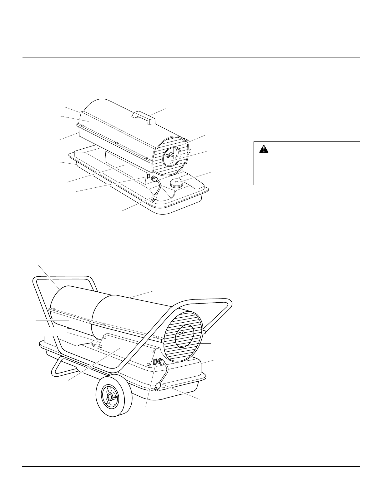
PRODUCT
IDENTIFICATION
Hot Air Outlet
Upper Shell
Lower Shell
Fuel Tank
Side Cover
ON/OFF Switch
with Light
Power
Cord
Figure 1 - B35CEH and B70CEH Models
Hot Air Outlet
Handle
Fan Guard
Air Filter
End Cover
Fuel Cap
UNPACKING
1. Remove all packing items applied to
heater for shipment.
2. Remove all items from carton.
3. Check items for any shipping damage.
If heater is damaged, promptly inform
dealer where you bought heater.
FUELS
WARNING: Use only kerosene
or No. 1 fuel oil to avoid risk of fire
or explosion. Never use gasoline,
naphtha, paint thinners, alcohol
or other highly flammable fuels.
Do not use heavy fuels such as No. 2 fuel oil
or No. 2 Diesel. Using heavy fuels will
result in:
• clogged fuel filter and nozzle
• use of non-toxic anti-icer in fuel during
very cold weather
IMPORTANT:
container. Be sure storage container is clean.
Foreign matter such as rust, dirt, or water
will cause the flame-out control to shut
down heater. Foreign matter may also require you to clean fuel system often.
Use a KEROSENE ONLY
Lower
Shell
Fuel Cap
Side Cover
Figure 2 - B100CEH and B150CEH Models
Upper Shell
Fan Guard
Fuel Tank
Power Cord
ON/OFF Switch
with Light
105398
3
Page 6

R
PORTABLE FORCED AIR HEATERS
ASSEMBLY
(FOR B100CEH AND
B150CEH MODELS ONLY)
These models are furnished with wheels and
handles. Wheels, handles, and the mounting
hardware are found in the shipping carton.
Tools Needed
• Medium Phillips Screwdriver
• 3/8" Open or Adjustable Wrench
• Hammer
1. Slide axle through wheel support
frame. Install wheels on axle.
IMPORTANT:
point extended hub of wheels toward
wheel support frame (see Figure 3).
When installing wheels,
2. Place cap nuts on axle ends. Gently tap
with hammer to secure.
3. Place heater on wheel support frame.
Make sure air inlet end (rear) of heater
is over wheels. Line up holes on fuel
tank flange with holes on wheel support frame.
4. Place front handle and rear handle on
top of fuel tank flange. Insert screws
through handles, fuel tank flange, and
wheel support frame. Attach nut finger
tight after each screw is inserted.
5. After all screws are inserted, tighten
nuts firmly.
Front Handle
VENTILATION
WARNING: Follow the minimum fresh, outside air ventilation
requirements. If proper fresh, outside air ventilation is not provided,
carbon monoxide poisoning can
occur. Provide proper fresh, outside air ventilation before running
heater.
Provide a fresh air opening of at least 2800
square cm (three square feet) for each 30kw
(100,000 Btu/Hr) rating. Provide extra fresh
air if more heaters are being used.
Example:
requires one of the following:
• a two-car garage door [4.9 meter (16 feet)
opening] raised 9 cm (3.5 inches)
• a single-car garage door [2.75 meter (9
feet) opening] raised 15.25 cm (6 inches)
• two, 76 cm (30 inch) windows raised 28
cm (11 inches)
A 44kw (150,000 Btu/Hr) heater
Screw
Hot Air
Outlet
Fuel Tank
Flange
Wheel
Support
Frame
Wheel
Cap Nut
Figure 3 - Wheel and Handle Assembly
Nut
Axle
Rear
Handle
Air
Inlet
Extended
Hub
4
105398
Page 7

OWNER’S MANUAL
THEORY OF
OPERATION
The Fuel System: The air pump forces air
through the air line. The air is then pushed
through the burner head nozzle. This air
causes fuel to lift from the tank. A fine mist
of fuel is sprayed into the combustion chamber.
The Air System: The motor turns the fan.
The fan pushes air into and around the
combustion chamber. This air is heated and
provides a stream of clean, hot air.
The Ignition System: The ignition control
assembly provides power to the ignitor.
This ignites the fuel/air mixture in the combustion chamber.
The Flame-Out Control System: This sys-
tem causes the heater to shut down if the
flame goes out.
Combustion Chamber
Ignitor
OPERATION
WARNING: Review and un-
derstand the warnings in the
Safety Information
2. They are needed to safely operate this heater. Follow all local
codes when using this heater.
TO START HEATER
1. Follow all ventilation and safety information.
2. Fill fuel tank with kerosene or No. 1
fuel oil.
3. Attach fuel cap.
4. Plug power cord of heater into standard
230 volt/50 hertz, grounded (earthed)
outlet. Use an extension cord if needed.
Use only a three-prong, grounded
(earthed) extension cord.
Motor
Fan
section, page
Air Pump
Air Intake
Filter
EXTENSION CORD WIRE
SIZE REQUIREMENTS
Up to 30.5 meters (100 feet) long, use 1.0
mm2 (16 AWG) conductor
30.6 to 61 meters (101 to 200 feet) long, use
1.5 mm
2
(14 AWG) conductor
Push ON/OFF switch to ON (|) position and
heater should start in 5 seconds. If heater
does not start, see Troubleshooting (page 7).
TO STOP HEATER
Push ON/OFF switch to OFF (O) position.
TO RESET HEATER
1. Push ON/OFF switch to OFF (O) position and wait 10 seconds (2 minutes if
heater has been running).
2. Repeat steps under To Start Heater.
ON/OFF Switch
|
with Light
O
Clean
Heated
Air Out
Fuel
Tank
Figure 4 - Cross Section Operational View
Nozzle
Air For Fuel System
Fuel
Filter
Air Line
To Burner
Air For Combustion
And Heating
Cool
Air
In
Air
Output
Filter
Ignition Control
Assembly
Fuel
Figure 5 - ON/OFF Switch, B35CEH and
B70CEH Models
ON/OFF Switch
|
with Light
O
Figure 6 - ON/OFF Switch, B100CEH and
B150CEH Models
105398
5
Page 8
R
PORTABLE FORCED AIR HEATERS
STORING,
TRANSPORTING,
OR SHIPPING
Note:
If shipping, transport companies re-
quire fuel tanks to be empty.
1. Drain fuel tank.
Note:
Some models have drain plug on
underside of fuel tank. If so, remove
drain plug to drain all fuel. If heater
does not have drain plug, drain fuel
through fuel cap opening. Be sure all
fuel is removed.
2. Replace drain plug if provided.
3. If any debris is noted in old fuel, add 1
or 2 quarts of clean kerosene to tank,
stir, and drain again. This will prevent
excess debris from clogging filters during future use.
4. Replace fuel cap or drain plug. Properly dispose of old and dirty fuel. Check
with local automotive service stations
that recycle oil.
5. If storing, store heater in dry place.
Make sure storage place is free of dust
and corrosive fumes.
IMPORTANT:
summer months for use during next heating
season. Using old fuel could damage heater.
Do not store kerosene over
PREVENTATIVE
MAINTENANCE
SCHEDULE
Item
Fuel tank
Air output and
lint filters
Air intake filter
Fuel filter
Ignitor
Fan blades
Motor
How Often
Flush every 150-200 hours of
operation or as needed
Replace every 500 hours of
operation or once a year
Wash and dry with soap and
water every 500 hours of operation or as needed
Clean twice a heating season
or as needed
No maintenance required
Clean every season or as
needed
Not required/permanently lu-
bricated
WARNING: Never service heater
while it is plugged in, operating, or hot.
Severe burns and electrical shock can
occur.
How To
See Storing, Transporting, or Ship-
ping
See Air Output, Air Intake, and Lint
Filters, page 10
See Air Output, Air Intake, and Lint
Filters, page 10
See Fuel Filter, page 8
See Fan, page 13
TROUBLESHOOTING
WARNING: Never service heater while it is plugged in, operating, or
hot. Severe burns and electrical shock can occur.
HEATER WITH FUSED OR NON-FUSED IGNITION CONTROL ASSEMBLY
FAULT CONDITION
Motor does not start five seconds after heater
is plugged in (ON/OFF switch light remains
on)
POSSIBLE CAUSE
1. Bad electrical connection between motor
and ignition control assembly or ignition
control assembly and power cord
WARNING: High voltage!
2. Binding pump rotor
3. Defective ignition control assembly
4. Defective motor
6
REMEDY
1. Check all electrical connections. See
Wiring Diagram, page 23
2. If fan does not turn freely, see Pump
Rotor, page 12
3. Replace ignition control assembly
4. Replace motor
105398
Page 9
TROUBLESHOOTING
Continued
OWNER’S MANUAL
FAULT CONDITION
Motor starts and runs but heater does not
ignite (ON/OFF switch light remains on)
Heater ignites but ignition control assembly
shuts heater off after a short period of time
(ON/OFF switch light remains on)
POSSIBLE CAUSE
1. No fuel in tank
2. Pump pressure incorrect
3. Dirty fuel filter
4. Obstruction in nozzle assembly
5. Water in fuel tank
WARNING: High voltage!
6. Bad electrical connection between
ignitor and ignition control assembly
7. Defective ignitor
8. Defective ignition control assembly
1. Pump pressure incorrect
2. Dirty air intake, air output, and/or lint
filter
3. Dirty fuel filter
4. Obstruction in nozzle assembly
5. Photocell assembly not properly
installed (not seeing the flame)
WARNING: High voltage!
REMEDY
1. Fill tank with kerosene
2. See Pump Pr essure Adjustment, page 10
3. See Fuel Filter, page 8
4. See Nozzle Assembly, page 11
5. Drain and flush fuel tank with clean
kerosene. See Storing, Transporting, or
Shipping, page 6
6. Check electrical connections. See Wiring
Diagram, page 23
7. Replace ignitor, see page 9
8. Replace ignition control assembly
1. See Pump Pr essure Adjustment, page 10
2. See Air Output, Air Intake, and Lint
Filters, page 10
3. See Fuel Filter, page 8
4. See Nozzle Assembly, page 11
5. Make sure photocell boot is properly
seated in bracket
6. Dirty photocell lens
7. Bad electrical connection between
photocell and ignition control assembly
8. Defective photocell
9. Defective ignition control assembly
6. Clean photocell lens
7. Check electrical connections. See Wiring
8. Replace photocell
9. Replace ignition control assembly
HEATER WITH NON-FUSED IGNITION CONTROL ASSEMBLY ONLY
ATTENTION:
Use the light in the ON/OFF switch to troubleshoot the fault condition.
FAULT CONDITION
ON/OFF switch light does not come on
when switch is turned to the ON (|) position
and heater does not start
ON/OFF switch light comes on when switch
is turned to the ON (|) Position but turns off
after five seconds
The ignition control has built-in protection against current overloads.
POSSIBLE CAUSE
1. No power to heater
WARNING: High voltage!
2. Bad electrical connections
3. Electrical short in ignitor
1. Electrical short in motor
WARNING: High voltage!
REMEDY
1. Verify that power cord is plugged into
2. Check electrical wiring and connections.
3. Check ignitor wiring. If no problems are
1. Check motor wiring. If no problems are
Diagram, page 23
an electrical outlet and that the circuit
breaker in the electral panel is reset
See W iring Diagram, page 23
found, replace ignitor (see page 9)
found, replace motor
105398
7
Page 10
R
PORTABLE FORCED AIR HEATERS
SERVICE
PROCEDURES
WARNING: Never service
heater while it is plugged in, operating, or hot. Severe burns and
electrical shock can occur.
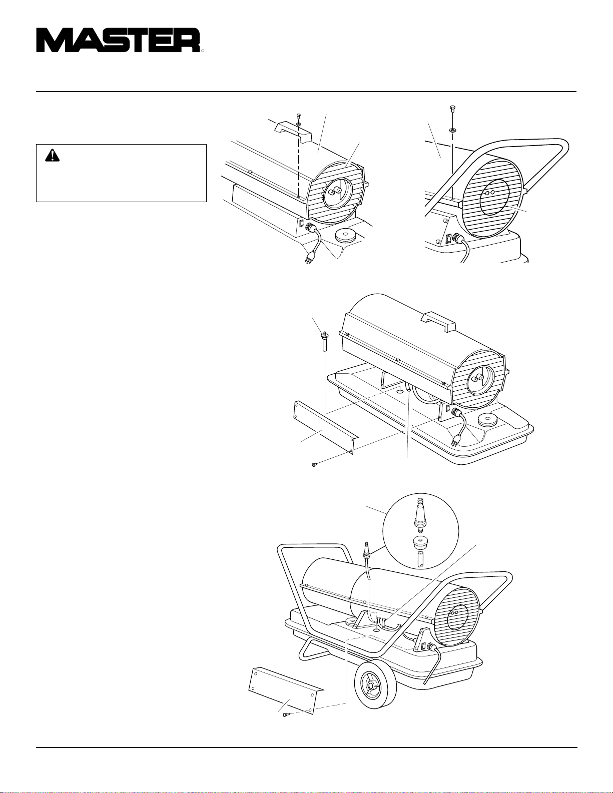
UPPER SHELL REMOVAL
1. Remove screws and lock washers along
each side of heater using 5/16" nutdriver. These screws attach upper and
lower shells together.
2. Lift upper shell off.
3. Remove fan guard.
FUEL FILTER
(B35CEH and B70CEH Models)
1. Remove side cover screws using 5/16"
nut-driver.
2. Remove side cover.
3. Pull rubber fuel line off fuel filter neck.
4. Carefully pry bushing and fuel filter out
of fuel tank.
5. W ash fuel filter with clean fuel and replace in tank.
6. Attach rubber fuel line to fuel filter
neck.
7. Replace side cover.
FUEL FILTER
(B100CEH and
B150CEH Models)
1. Remove side cover screws using 5/16"
nut-driver.
2. Remove side cover.
3. Pull upper fuel line off fuel filter neck.
4. Carefully pry bushing, lower fuel line,
and fuel filter out of fuel tank.
5. W ash fuel filter with clean fuel and replace in tank.
6. Attach upper fuel line to fuel filter neck.
7. Replace side cover.
Upper Shell
Fan
Guard
Figure 7 - Upper Shell Removal, B35CEH
and B70CEH Models
Fuel Filter
Side Cover
Figure 9 - Fuel Filter Removal, B35CEH and B70CEH Models
Fuel Filter, Bushing,
and Lower Fuel Line
Upper
Shell
Figure 8 - Upper Shell Removal, B100CEH
and B150CEH Models
Fuel Line
Fan
Guard
Upper Fuel
Line
Side Cover
Figure 10 - Fuel Filter Removal, B100CEH and B150CEH Models
8
105398
Page 11
OWNER’S MANUAL
SERVICE
PROCEDURES
Continued
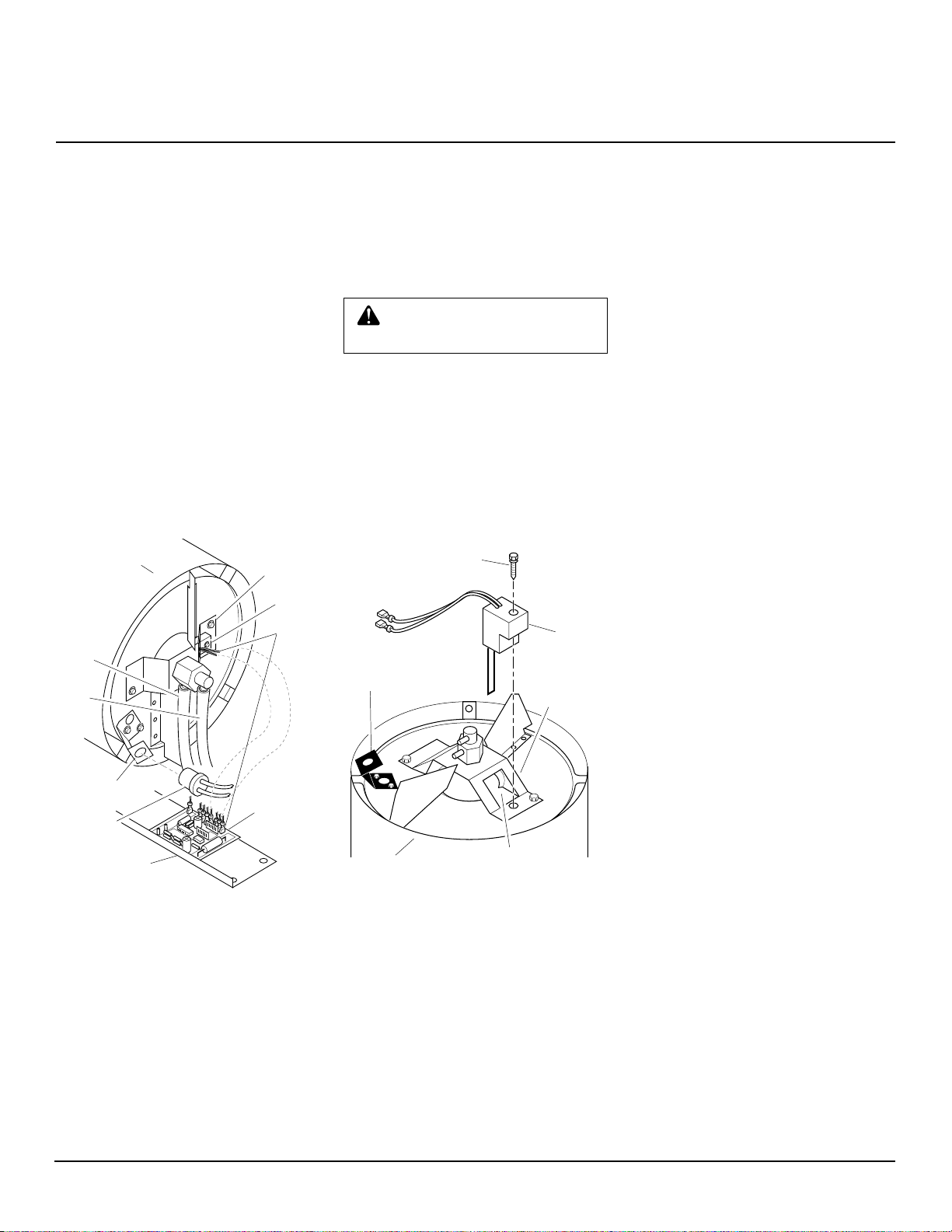
IGNITOR
1. Remove upper shell and fan guard (see
page 8).
2. Remove fan (see page 13).
3. Remove 4 side cover screws with a
5/16" nut driver. Remove side cover
(see Figure 9 or 10, page 8).
4. Disconnect ignitor wires (black) from
ignition control assembly (see Figure
11). Pull the ignitor wires up through
the hole in the lower shell.
5. Disconnect fuel line hose and air line
hose. Remove photocell from photocell
bracket (see Figure 11).
Combustion
Chamber
Nozzle
Adapter
Bracket
Ignitor
6. Remove combustion chamber. Stand
combustion chamber on end with
nozzle adapter bracket on top (see Figure 12).
7. Remove ignitor screw with a 1/4" nut
driver. Carefully remove ignitor from
nozzle adapter bracket.
CAUTION: Do not bend or strike
ignitor element. Handle with care.
8. Carefully remove replacement ignitor
from styrofoam packing.
9. Carefully guide ignitor into opening in
nozzle adapter bracket. Do not strike
ignitor element. Attach ignitor to
nozzle adapter bracket with screw using a 1/4" nut driver (see Figure 12).
T orque .90 to 1.69 N-m (8 to 15 in-lbs)
Do not over torque.
Ignitor Screw/Washer
Assembly
10. Replace combustion chamber.
11. Route the ignitor wires back down
through the hole in the lower shell.
Connect wires to the ignition control
assembly.
12. Replace side cover (see Figure 9 or 10,
page 8).
13. Connect and route fuel line hose and
air line hose to burner head. See Fuel
and Air Line Replacement and Proper
Routing, page 11.
14. Replace photocell in photocell bracket.
Route wires as shown in either Figure
17, 18, or 19, page 11.
15. Replace fan (see page 13).
16. Replace fan guard and upper shell (see
page 8).
Air
Line
Hose
Fuel
Line
Hose
Photocell
Bracket
Photocell
Assembly
Side Cover
Figure 11 - Disconnecting Ignitor Wires
from Ignition Control Assembly
Ignitor
Wires
Ignition
Control
Assembly
Ignitor
Element
Photocell
Bracket
Combustion
Chamber
Figure 12 - Ignitor Replacement
Nozzle Adapter
Bracket Opening
Nozzle
Adapter
Bracket
Ignitor
105398
Continued
9
Page 12

R
PORTABLE FORCED AIR HEATERS
SERVICE
PROCEDURES
Continued
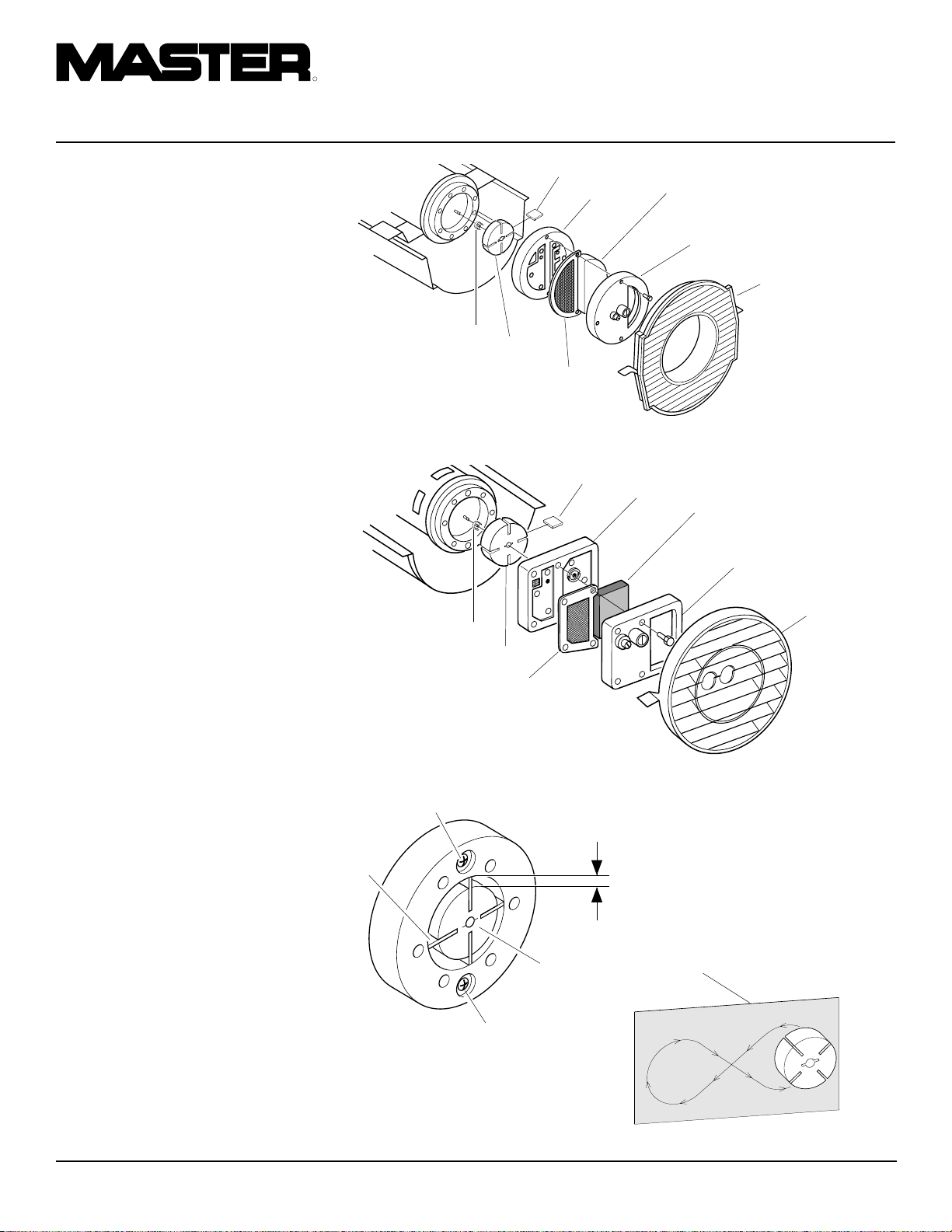
AIR OUTPUT, AIR INTAKE,
AND LINT FILTERS
1. Remove upper shell (see page 8).
2. Remove filter end cover screws using
5/16" nut-driver.
3. Remove filter end cover.
4. Replace air output and lint filters.
5. Wash or replace air intake filter (see
Preventative Maintenance Schedule,
page 6).
6. Replace filter end cover.
7. Replace fan guard and upper shell.
IMPORTANT:
PUMP PRESSURE
ADJUSTMENT
1. Remove pressure gauge plug from filter
end cover.
2. Install accessory pressure gauge (part
number HA1180).
3. Start heater (see Operation, page 5).
Allow motor to reach full speed.
4. Adjust pressure. Turn relief valve to
right to increase pressure. Turn relief
valve to left to decrease pressure. See
specifications below for correct pressure for each model.
5. Remove pressure gauge. Replace pressure gauge plug in filter end cover.
Do not oil filters
Air Intake Filter
Filter End
Cover
Lint Filter
Air Output
Filter
Figure 13 - Air Output, Air Intake, and Lint Filters, B35CEH and B70CEH Models
Air Intake Filter
Filter End
Cover
Lint Filter
Air Output
Filter
Figure 14 - Air Output, Air Intake, and Lint Filters, B100CEH and B150CEH Models
Pressure
Gauge
Plug
Relief
Valve
Model (Bar/PSI)
B35CEH 0.200/2.9
B70CEH 0.338/4.9
B100CEH 0.338/4.9
B150CEH 0.380/5.5
Fan Guard
Fan Guard
Pump
Pressure
Plastic Cap
Figure 15 - Pressure Gauge Plug Removal
(B35CEH and B70CEH Models Shown)
10
Pressure
Gauge
Figure 16 - Adjusting Pump Pressure
105398
Page 13
OWNER’S MANUAL
SERVICE
PROCEDURES
Continued
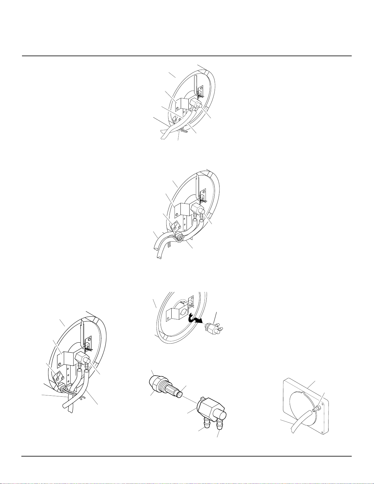
NOZZLE ASSEMBLY
1. Remove upper shell (see page 8).
2. Remove fan (see page 13).
3. Remove fuel and air line hoses from
nozzle assembly (see Figure 17, 18 or 19).
4. Turn nozzle assembly 1/4 turn to left
and pull toward motor to remove (see
Figure 20).
5. Place plastic hex-body into vise and
lightly tighten.
6. Carefully remove nozzle from the
nozzle adapter using 5/8" socket
wrench (see Figure 21).
7. Blow compressed air through face of
nozzle. This will free any dirt in nozzle
area.
8. Inspect nozzle seal for damage.
9. Replace nozzle into nozzle adapter until nozzle seats. Tighten 1/3 turn more
using 5/8" socket wrench 4.5 to 5.1 Nm (40 to 45 in-lbs). See Figure 21.
10. Attach nozzle assembly to burner strap.
11. Attach fuel and airline hoses to nozzle
assembly. See Fuel and Airline Re-
placement and Proper Routing.
12. Replace fan (see page 13).
13. Replace fan guard and upper shell (see
page 8).
Combustion
Chamber
Nozzle
Adapter
Bracket
Photocell
Bracket
Nozzle/
Adapter
Assembly
Air Line
Hose
Fuel Line Hose
Figure 17 - Removing Air and Fuel Line
Hoses (B35CEH and B70CEH Models
Only)
Combustion
Chamber
Nozzle Adapter
Bracket
Air Line
Hose
Photocell Bracket
Figure 18 - Removing Air and Fuel Line
Hoses (B100CEH Model Only)
Combustion
Chamber
Nozzle Adapter
Bracket
Photocell
Bracket
Air Line
Hose
Fuel Line Hose
Figure 19 - Removing Air and Fuel Line
Hoses (B150CEH Model Only)
Combustion
Chamber
Figure 20 - Removing Nozzle/Adapter
Assembly
Nozzle Face
Nozzle Seal
Nozzle
Nozzle Adapter
Air Line Fitting
Figure 21 - Nozzle and Nozzle Adapter
Nozzle/
Adapter
Assembly
Fuel Line
Hose
Nozzle/
Adapter
Assembly
Nozzle/
Adapter
Assembly
Fuel Line Fitting
FUEL AND AIR LINE
REPLACEMENT AND
PROPER ROUTING
1. Remove upper shell (see page 8).
2. Remove side cover screws using 5/16"
nut driver.
3. Remove side cover.
4. Inspect fuel and air line hoses for cracks
and/or holes. If fuel line hose is damaged,
disconnect from nozzle adapter (see Figure 17, 18, or 19) and from fuel filter (see
page 8). If air line hose is damaged, disconnect from nozzle adapter (see Figure
17, 18, or 19) and from barb fitting on
pump end cover (see Figure 22).
5. Install new air and/or fuel line. Attach
one end of air line hose to barb fitting
on pump end cover (see Figure 22) and
the other end to nozzle adapter (see
Figure 17, 18, or 19). Attach one end
of fuel line hose to fuel filter (see page
8) and the other end to nozzle adapter
(see Figure 17, 18, or 19).
For B35CEH and B70CEH model heaters, route air and fuel lines approximately as shown in Figure 17.
Note:
Hoses are not to be touching pho-
tocell bracket.
For B100CEH model heater, route air
and fuel lines approximately as shown
in Figure 18.
Note:
Hoses are not to be touching pho-
tocell bracket.
For B150CEH model heater, route air
and fuel lines approximately as shown
in Figure 19.
Note:
Hoses are not to be touching pho-
tocell bracket
6. Replace side cover.
7. Replace upper shell and fan guard (see
page 8).
Pump End Cover
Barb Fitting
Air Hose
Figure 22 - Air Hose to Barb FItting
Continued
Continued
105398
11
Page 14
R
PORTABLE FORCED AIR HEATERS
SERVICE
PROCEDURES
Continued
PUMP ROTOR
(Procedure if Rotor is Binding)
1. Remove upper shell (see page 8).
2. Remove filter end cover screws using
5/16" nut-driver.
3. Remove filter end cover and air filters.
4. Remove pump plate screws using 5/16"
nut-driver.
5. Remove pump plate.
6. Remove rotor, insert, and blades.
7. Check for debris in pump. If debris is
found, blow out with compressed air.
8. Install insert and rotor.
9. Check gap on rotor. Adjust to .076/.101
mm (.003"/.004") if needed (see Figure 25).
Note:
Rotate rotor one full turn to ensure
the gap is .076/.101 mm (.003"/.004") at
tightest position. Adjust if needed.
10. Install blades, pump plate, air filters,
and filter end cover.
11. Replace fan guard and upper shell.
12. Adjust pump pressure (see page 10).
Note:
If rotor is still binding, proceed as
follows.
13. Perform steps 1 through 6 above.
14. Place fine grade sandpaper (600 grit)
on flat surface. Sand rotor lightly in
“figure 8” motion four times (see Figure 26).
15. Reinstall insert and rotor.
16. Perform steps 10 through 12 above.
Blade
Pump
Plate
Insert
Figure 23 - Rotor Location, B35CEH and B70CEH Models
Insert
Figure 24 - Rotor Location, B100CEH and B150CEH Models
Gap Adjusting
Screw
Blade
Rotor
Air Output
Filter
Blade
Rotor
Air Output
Filter
.076/.101 mm (.003"/.004") Gap
Measured With Feeler Gauge
Air
Intake
Filter
Filter End
Cover
Pump
Plate
Air Intake Filter
Filter End
Cover
Fan Guard
Fan Guard
Rotor
Gap Adjusting
Screw
Figure 25 - Gap Adjusting Screw Locations
12
Sandpaper
Figure 26 - Sanding Rotor
105398
Page 15

OWNER’S MANUAL
SERVICE
PROCEDURES
Continued
FAN
IMPORTANT:
shaft before removing motor from heater.
The weight of the motor resting on the fan
could damage the fan pitch.
1. Remove upper shell (see page 8).
2. Use 1/8" allen wrench to loosen set-
screw which holds fan to motor shaft.
3. Slip fan off motor shaft.
4. Clean fan using a soft cloth moistened
with kerosene or solvent.
5. Dry fan thoroughly.
6. Replace fan on motor shaft. Place fan
hub flush with end of motor shaft (see
Figure 28).
7. Place setscrew on flat of shaft. Tighten
setscrew firmly 4.5 to 5.6 N-m (40 to
50 in-lbs).
8. Replace fan guard and upper shell.
Setscrew
Remove fan from motor
Fan
IGNITION CONTROL
ASSEMBLY
WARNING: Unplug heater
before servicing.
Remove Old Assembly
1. Using the 5/16" nut driver or socket
wrench, remove the four side cover
screws (see Figure 29).
2. Disconnect the nine wires from the
ignition control assembly.
3. Using needle nose pliers, squeeze the tab
on the printed circuit board support and
lift up on the edge of the ignition control
assembly (see Figure 30). Repeat this for
the other four printed circuit board supports then remove the assembly.
Side
Cover
Figure 29 - Removing Cover
Installing the New Assembly
CAUTION: Ignition control
assembly contains electrostatic
components. Handle the assembly by the edges of the printed
circuit board. Do not touch any
of the quick connect terminals
or electronic components.
1. Align the five holes in the assembly
with the five printed circuit board supports in the side cover.
2. Holding the assembly by the edges of
the printed circuit board, apply downward pressure until all five tabs on the
printed circuit board supports springlock
into place. Pull up on assembly to verify
this (see Figure 31).
3. Connect the nine wire leads to the
ignition control assembly as shown
in the wiring diagram on page 23.
CAUTION: Double check
connections. Connecting ignition control assembly wrong
could result in damage to the
ignition control assembly and/
or other components in the
heater assembly.
Motor
Shaft
Figure 27 - Fan, Motor Shaft, and Setscrew
Location
Fan
Flush
Motor
Shaft
Setscrew
Figure 28 - Fan Cross Section
105398
Side Cover
Ignition
Control
Assembly
Figure 30 - Removing Circuit Board
Printed Circuit
Board Supports (5)
13
4. Using the 5/16" nut driver or socket
wrench reinstall side cover to heater.
Tighten screws until snug. Do not over
torque!
Unacceptable Acceptable
Unacceptable Acceptable
Figure 31 - Attaching Circuit Board to
Tabs
Page 16

R
1
2
3
4
5
6
7
8
9
10
11
12
13
16
9-2
9-1
9-3
9-4
9-5
17
18
19
20
21
22
23
24
26
27
28
29
30
34
35
36
32
33
9-6
15
14
31
42
41
43
40
38
37
39
25
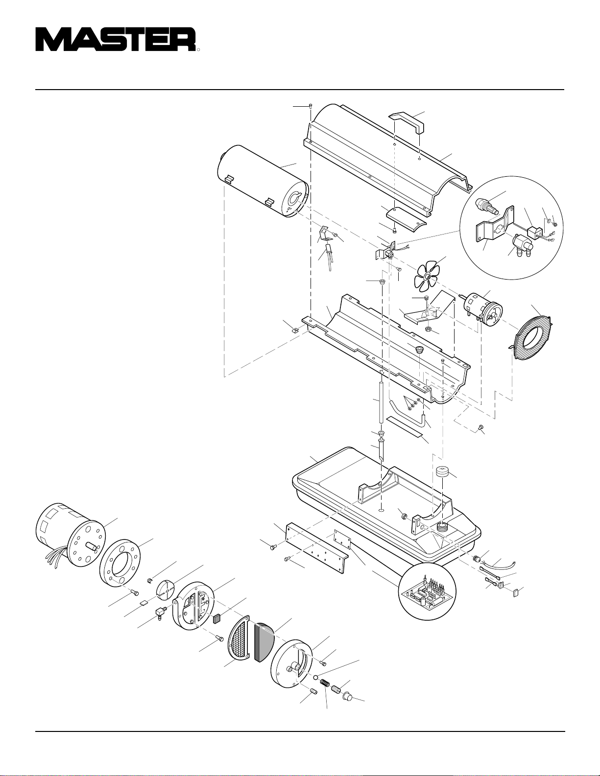
PORTABLE FORCED AIR HEATERS
ILLUSTRATED
PARTS
BREAKDOWN
B35CEH MODEL
12-1
12-2
12-18
12-17
12-16
Motor and Pump Assembly
12-3
12-15
12-4
12-14
12-5
12-6
12-7
12-8
12-9
12-13
12-10
12-12
12-11
14
12-19
105398
Page 17
OWNER’S MANUAL
PARTS LIST
B35CEH MODEL
KEY PART
NO. NUMBER DESCRIPTION QTY.
1 M51104-01 Handle 1
2 098511-256 Upper Shell 1
3 M11084-29 Screw, #10-16 x 3/4" 2
4 102432-01 Screw/Lockwasher, 1/2" 6
5 098512-63 Combustion Chamber 1
6 M10908-2 Screw, #6-32 x 3/8" 2
7 103154-03 Photocell Bracket 1
8 M16656-24 Photocell Assembly 1
9 ∗∗ Burner Strap Assembly 1
9-1 HA3006 Nozzle Assembly 1
9-2 102548-05 Ignitor Kit 1
9-3 104056-01 Nozzle Adapter 1
9-4 102336-01 Nozzle Adapter Bracket 1
9-5 M10908-75 Screw, #6-32 x 7/8" 1
9-6 103347-01 Belleville Washer 1
10 102431-01 Screw/Lockwasher, 1/2" 2
11 103684-01 Fan 1
12 ∗∗ Motor and Pump Assembly 1
12-1 102001-25 Motor 1
12-2 079975-03 Pump Body 1
12-3 M22009 Insert 1
12-4 M22456-2 Rotor 1
12-5 M29608 Pump End Cover 1
12-6 M29632 Lint Filter 1
12-7 M29633 Intake Filter 1
12-8 M29609 Filter End Cover 1
12-9 M12461-31 Screw, #10-32 x 1" 3
12-10 M27694 Adjusting Screw 1
12-11 M10993-1 Pressure Relief Spring 1
12-12 M22997 Plug 1
12-13 M8940 Steel Ball, 1/4" Diameter 1
12-14 M29612-01 Output Filter 1
12-15 M12461-32 Screw #10-32 x 1
12-16 103676-01 Nylon Elbow, 90° 1
12-17 M8643-2 Blade 4
12-18 FHPF3-6C Screw, #10-32 x 3/4" 2
12-19 105780-01 Plastic Cap 1
13 M51105-01 Fan Guard 1
This list contains replaceable parts used in your heater. When ordering parts, be sure to
provide the correct model and serial numbers (from the model plate), then the part number
and description of the desired part.
1
/8"6
KEY PART
NO. NUMBER DESCRIPTION QTY.
14 079673-07 Power Cord 1
15 M50400 Strain Relief Bushing 1
16 NTC-4C Hex Lock Nut, 1/4-20 2
17 102431-01 Screw/Lockwasher, 1/2" 4
18 M50631 Rubber Bumper 2
19 097461-09 Side Cover 1
20 101205-01 Motor Bracket 1
21 M30865-02 Bushing 1
22 M11271-8 Clip Nut 6
23 M50104-02 Bushing 1
24 102431-01 Screw/Lockwasher, 1/2" 6
25 RF3-4B Screw, #10-32 x 1/2" 1
26 098511-237 Lower Shell 1
27 M50814-06 Rubber Airline 1
28 M29652-05 Fuel Line 1
29 108060-01 Fuel Filter 1
30 M10990-3 Rubber Bushing 1
31 102861-01 Nylon Locknut 1
32 102349-01 PCB Support 5
33 104068-04 Ignition Control Assembly 1
34 097702-01 Fuel Cap (Includes Gasket) 1
35 108088-01 Fuel Tank 1
36 M51108-01 Shell Heat-Shield 1
37 NPF-3B Nut, #10-32 3
38 097785-01 Vinyl Foam Gasket 1
39 WLE-3 Lockwasher, #10 1
40 079010-39 Wire Assembly (Brown) 1
41 105793-01 ON/OFF Switch 1
42 079919-01 Switch Cover 1
43 079010-40 Wire Assembly (White) 1
PARTS AVAILABLE - NOT SHOWN
HA2210 Filler Neck Screen 1
103814-01 Wire Tie 1
097649-01 Tradename Decal 2
106013-01 Decal Package 1
105880-01 Ignition Control Assembly Fuse 1
∗∗ Not available as an assembly; order parts separately
105398
15
Page 18
R
1
2
3
4
5
6
7
8
9
10
11
12
13
16
9-2
9-1
9-3
9-4
9-5
17
18
19
20
21
22
23
24
26
27
28
29
30
34
35
36
32
33
9-6
15
14
31
42
41
43
40
38
37
39
25
PORTABLE FORCED AIR HEATERS
ILLUSTRATED
PARTS
BREAKDOWN
B70CEH MODEL
12-1
12-2
12-18
12-17
12-16
Motor and Pump Assembly
12-3
12-15
12-4
12-14
12-5
12-6
12-7
12-8
12-9
12-13
12-10
12-12
12-11
16
12-19
105398
Page 19

OWNER’S MANUAL
PARTS LIST
B70CEH MODEL
KEY PART
NO. NUMBER DESCRIPTION QTY.
1 M51104-01 Handle 1
2 098511-256 Upper Shell 1
3 M11084-29 Screw, #10-16 x 3/4" 2
4 102432-01 Screw/Lockwasher, 1/2" 6
5 098512-64 Combustion Chamber 1
6 M10908-2 Screw, #6-32 x 3/8" 2
7 103154-03 Photocell Bracket 1
8 M16656-24 Photocell Assembly 1
9 ∗∗ Burner Strap Assembly 1
9-1 HA3026 Nozzle Assembly 1
9-2 102548-05 Ignitor Kit 1
9-3 104056-01 Nozzle Adapter 1
9-4 102336-01 Nozzle Adapter Bracket 1
9-5 M10908-75 Screw, #6-32 x 7/8" 1
9-6 103347-01 Belleville Washer 1
10 102431-01 Screw/Lockwasher, 1/2" 2
11 103684-01 Fan 1
12 ∗∗ Motor and Pump Assembly 1
12-1 102001-23 Motor 1
12-2 079975-02 Pump Body 1
12-3 M22009 Insert 1
12-4 M22456-1 Rotor 1
12-5 M29608 Pump End Cover 1
12-6 M29632 Lint Filter 1
12-7 M29633 Intake Filter 1
12-8 M29609 Filter End Cover 1
12-9 M12461-31 Screw, #10-32 x 1" 3
12-10 M27694 Adjusting Screw 1
12-11 M10993-1 Pressure Relief Spring 1
12-12 M22997 Plug 1
12-13 M8940 Steel Ball, 1/4" Diameter 1
12-14 M29612-01 Output Filter 1
12-15 M12461-31 Screw #10-32 x 1" 6
12-16 103676-01 Nylon Elbow, 90° 1
12-17 M8643 Blade 4
12-18 FHPF3-5C Screw, #10-32 x 5/8" 2
12-19 105780-01 Plastic Cap 1
13 M51105-01 Fan Guard 1
This list contains replaceable parts used in your heater. When ordering parts, be sure to
provide the correct model and serial numbers (from the model plate), then the part number
and description of the desired part.
KEY PART
NO. NUMBER DESCRIPTION QTY.
14 079673-07 Power Cord 1
15 M50400 Strain Relief Bushing 1
16 NTC-4C Hex Lock Nut, 1/4-20 2
17 102431-01 Screw/Lockwasher, 1/2" 4
18 M50631 Rubber Bumper 2
19 097461-09 Side Cover 1
20 101205-01 Motor Bracket 1
21 M30865-02 Bushing 1
22 M11271-8 Clip Nut 6
23 M50104-02 Bushing 1
24 102431-01 Screw/Lockwasher, 1/2" 6
25 RF3-4B Screw, #10-32 x 1/2" 1
26 098511-237 Lower Shell 1
27 M50814-06 Rubber Airline 1
28 M29652-05 Fuel Line 1
29 108060-03 Fuel Filter 1
30 M10990-3 Rubber Bushing 1
31 102861-01 Nylon Locknut 1
32 102349-01 PCB Support 5
33 104068-04 Ignition Control Assembly 1
34 097702-01 Fuel Cap (Includes Gasket) 1
35 108088-03 Fuel Tank 1
36 M51108-01 Shell Heat-Shield 1
37 NPF-3B Nut, #10-32 3
38 097785-01 Vinyl Foam Gasket 1
39 WLE-3 Lockwasher, #10 1
40 079010-39 Wire Assembly (Brown) 1
41 105793-01 ON/OFF Switch 1
42 079919-01 Switch Cover 1
43 079010-40 Wire Assembly (White) 1
PARTS AVAILABLE - NOT SHOWN
HA2210 Filler Neck Screen 1
103814-01 Wire Tie 1
097649-01 Tradename Decal 2
106013-02 Decal Package 1
105880-01 Ignition Control Assembly Fuse 1
∗∗ Not available as an assembly; order parts separately
105398
17
Page 20

R
PORTABLE FORCED AIR HEATERS
ILLUSTRATED
PARTS
BREAKDOWN
B100CEH MODEL
2
1
3
7-4
7
4
6
24
28
5
8
11
23
20
22
19
25
18
9
10
12
15
26
27
7-1
7-2
7-6
7-3
7-5
16
29
10-1
10-2
10-3
10-4
10-17
10-16
10-15
10-13
Motor and Pump Assembly
10-14
10-5
10-13
35
10-6
30
43
36
32
21
31
14
17
10-7
41
42
37
13
33
34
44
39
38
14
40
10-8
10-9
10-10
10-11
10-12
18
105398
Page 21
OWNER’S MANUAL
PARTS LIST
B100CEH MODEL
KEY PART
NO. NUMBER DESCRIPTION QTY.
1 098511-257 Upper Shell 1
2 102432-01 Screw/Lockwasher, 1/2" 8
3 098512-65 Combustion Chamber 1
4 103971-01 Photocell Bracket 1
5 M10908-2 Screw, #6-32 x 3/8" 2
6 M16656-24 Photocell Assembly 1
7 ** Burner Strap Assembly 1
7-1 HA3027 Nozzle Assembly 1
7-2 102548-05 Ignitor Kit 1
7-3 M10908-75 Screw, #6-32 x 7/8" 1
7-4 102336-01 Nozzle Adapter Bracket 1
7-5 104054-01 Nozzle Adapter 1
7-6 103347-01 Belleville Washer 1
8 102431-01 Screw/Lockwasher, 1/2" 2
9 102042-01 Fan 1
10 ** Motor and Pump Assembly 1
10-1 102001-24 Motor 1
10-2 079975-02 Pump Body 1
10-3 FHPF3-5C Screw, #10-32 x 5/8" 2
10-4 M22009 Rotor Insert 1
10-5 M22456-1 Pump Rotor 1
10-6 M50545 Pump End Cover 1
10-7 M12179 Intake Filter 1
10-8 M16545 Filter End Cover 1
10-9 M8940 Steel Ball, 1/4" Diameter 1
10-10 M10993-1 Relief Spring 1
10-11 M27694 Adjusting Screw 1
10-12 M22997 Plug 1
10-13 M12461-31 Screw, #10-32 x 1" 10
10-14 M12244-1 Output Filter 1
10-15 M11637 Lint Filter 1
10-16 M50820-02 Barb Fitting 1
10-17 M8643 Blade 4
11 M50631 Rubber Bumper 2
12 101206-01 Motor Mounting Bracket 1
13 101695-01 Button Plug 1
14 104068-04 Ignition Control Assembly 1
This list contains replaceable parts used in your heater. When ordering parts, be sure to provide the
correct model and serial numbers (from the model plate), then the part number and description of the
desired part.
KEY PART
NO. NUMBER DESCRIPTION QTY.
15 NTC-4C Hex Lock Nut, 1/4-20 2
16 M51114-01 Fan Guard 1
17 M27417 Drain Plug (Includes “o” Ring) 1
18 099213-01 Button Plug 1
19 M51345-01 Fuel Line 1
20 107961-01 Fuel Filter 1
21 M51151-01 Fuel Line Tube 1
22 M10990-3 Rubber Bushing 1
23 M50814-03 Airline 1
24 098511-236 Lower Shell 1
25 M50104-03 Bushing 1
26 M50104-01 Bushing 1
27 102431-01 Screw/Lockwasher, 1/2" 6
28 M11271-8 Clip Nut 8
29 RF3-4B Screw, #10-32 x 1/2" 1
30 108088-04 Fuel Tank 1
31 097702-01 Fuel Cap (Includes Gasket) 1
32 102349-01 P.C. Board Support 5
33 M50400 Strain Relief Bushing 1
34 079673-07 Power Cord 1
35 M51077-15 Side Cover 1
36 102431-01 Screw/Lockwasher, 1/2" 4
37 102861-01 Nylon Locknut 1
38 079010-39 Wire Assembly (Brown) 1
39 105793-01 ON/OFF Switch 1
40 079919-01 Switch Cover 1
41 WLE-3 Lockwasher, #10 1
42 NPF-3B Nut, #10-32 3
43 097468-01 Edge Liner 1
44 079010-40 Wire Assembly (White) 1
PARTS AVAILABLE - NOT SHOWN
HA2210 Filler Neck Screen 1
103814-01 Wire Tie 1
097650-01 Tradename Decal 2
106013-03 Decal Package 1
105880-01 Ignition Control Assembly Fuse 1
** Not available as an assembly; order parts separately
105398
19
Page 22

R
PORTABLE FORCED AIR HEATERS
ILLUSTRATED
PARTS
BREAKDOWN
B150CEH MODEL
2
1
3
7-4
7
4
6
24
28
5
8
11
23
20
22
19
25
18
9
10
12
15
26
27
7-1
7-2
7-6
7-3
7-5
16
29
10-1
10-2
10-3
10-4
10-17
10-16
10-15
10-18
Motor and Pump Assembly
10-14
10-5
10-13
35
10-6
30
43
36
32
21
31
14
17
10-7
41
42
37
13
33
34
44
39
38
14
40
10-8
10-9
10-10
10-11
10-12
20
105398
Page 23

OWNER’S MANUAL
PARTS LIST
B150CEH Model
KEY PART
NO. NUMBER DESCRIPTION QTY.
1 098511-257 Upper Shell 1
2 102432-01 Screw/Lockwasher, 1/2" 8
3 098512-66 Combustion Chamber 1
4 103154-05 Photocell Bracket 1
5 M10908-2 Screw, #6-32 x 3/8" 2
6 M16656-24 Photocell Assembly 1
7 ** Burner Strap Assembly 1
7-1 100735-24 Nozzle Assembly 1
7-2 102548-05 Ignitor Kit 1
7-3 M10908-75 Screw, #6-32 x 7/8" 1
7-4 102336-01 Nozzle Adapter Bracket 1
7-5 104054-01 Nozzle Adapter 1
7-6 103347-01 Belleville Washer 1
8 102431-01 Screw/Lockwasher, 1/2" 2
9 102042-01 Fan 1
10 ** Motor and Pump Assembly 1
10-1 102001-24 Motor 1
10-2 079975-03 Pump Body 1
10-3 FHPF3-6C Screw, #10-32 x 3/4" 2
10-4 M22009 Rotor Insert 1
10-5 M22456-2 Pump Rotor 1
10-6 M50545 Pump End Cover 1
10-7 M12179 Intake Filter 1
10-8 M16545 Filter End Cover 1
10-9 M8940 Steel Ball, 1/4" Diameter 1
10-10 M10993-1 Relief Spring 1
10-11 M27694 Adjusting Screw 1
10-12 M22997 Plug 1
10-13 M12461-31 Screw, #10-32 x 1" 4
10-14 M12244-1 Output Filter 1
10-15 M11637 Lint Filter 1
10-16 M50820-02 Barb Fitting 1
10-17 M8643-2 Blade 4
10-18 M12461-32 Screw, #10-32 x 1
11 M50631 Rubber Bumper 2
12 101206-01 Motor Mounting Bracket 1
13 101695-01 Button Plug 1
14 104068-04 Ignition Control Assembly 1
This list contains replaceable parts used in your heater. When ordering parts, be sure to provide the
correct model and serial numbers (from the model plate), then the part number and description of the
desired part.
1
/8"6
KEY PART
NO. NUMBER DESCRIPTION QTY.
15 NTC-4C Hex Lock Nut, 1/4-20 2
16 M51114-01 Fan Guard 1
17 M27417 Drain Plug (Includes “o” Ring) 1
18 099213-01 Button Plug 1
19 M51345-04 Fuel Line 1
20 107961-01 Fuel Filter 1
21 M51151-02 Fuel Line Tube 1
22 M10990-3 Rubber Bushing 1
23 M50814-03 Airline 1
24 098511-236 Lower Shell 1
25 M50104-03 Bushing 1
26 M50104-01 Bushing 1
27 102431-01 Screw/Lockwasher, 1/2" 6
28 M11271-8 Clip Nut 8
29 RF3-4B Screw, #10-32 x 1/2" 1
30 108088-05 Fuel Tank 1
31 097702-01 Fuel Cap (Includes Gasket) 1
32 102349-01 P.C. Board Support 5
33 M50400 Strain Relief Bushing 1
34 079673-07 Power Cord 1
35 M51077-15 Side Cover 1
36 102431-01 Screw/Lockwasher, 1/2" 4
37 102861-01 Nylon Locknut 1
38 079010-39 Wire Assembly (Brown) 1
39 105793-01 ON/OFF Switch 1
40 079919-01 Switch Cover 1
41 WLE-3 Lockwasher, #10 1
42 NPF-3B Nut, #10-32 3
43 097468-01 Edge Liner 1
44 079010-40 Wire Assembly (White) 1
PARTS AVAILABLE - NOT SHOWN
HA2210 Filler Neck Screen 1
103814-01 Wire Tie 1
097650-01 Tradename Decal 2
106013-04 Decal Package 1
105880-01 Ignition Control Assembly Fuse 1
** Not available as an assembly; order parts separately
105398
21
Page 24
R
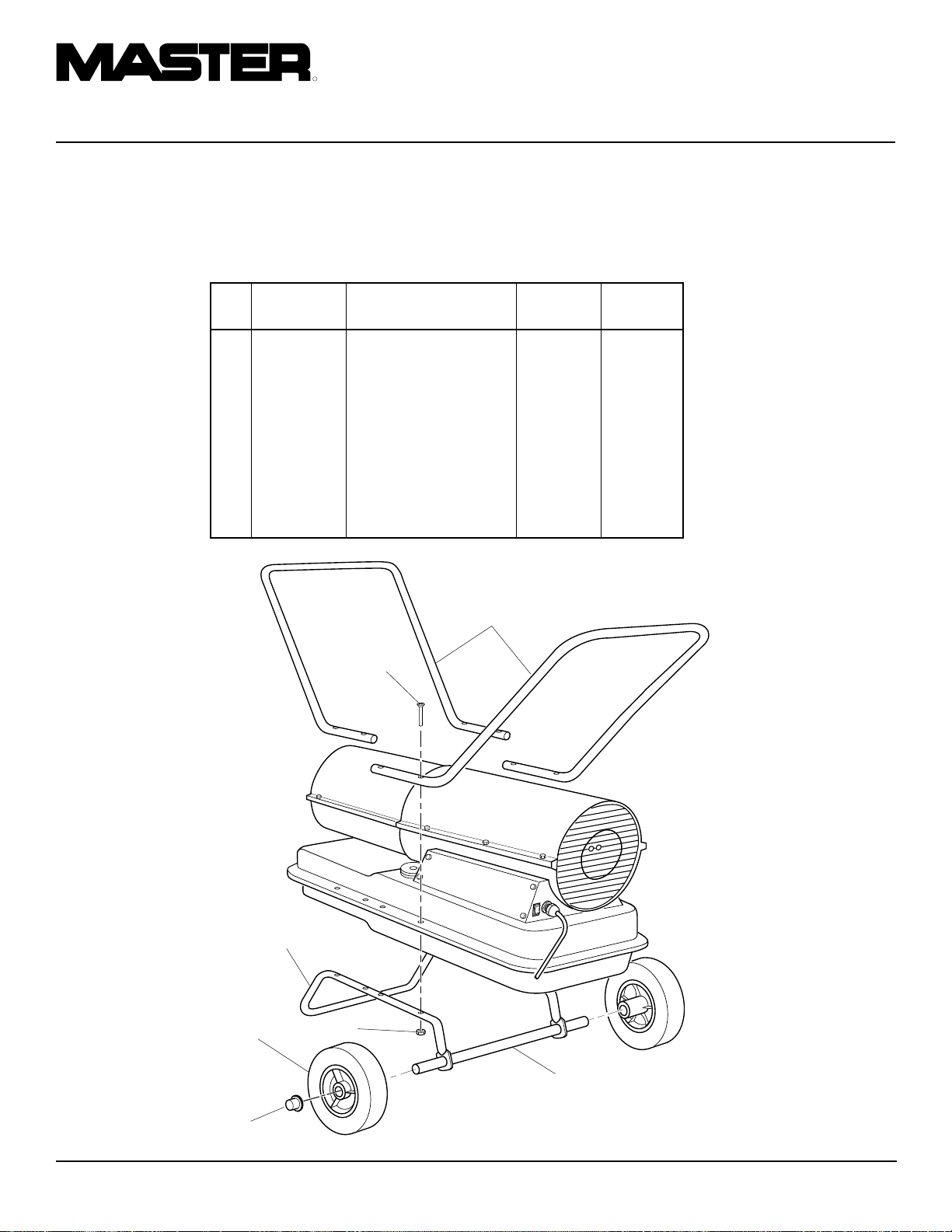
PORTABLE FORCED AIR HEATERS
WHEELS AND
HANDLES
B100CEH AND B150CEH
MODELS
KEY PART PART B100CEH B150CEH
NO. NUMBER DESCRIPTION QTY. QTY.
1 HA2203 Handles 2 —
HA2204 Handles — 2
2 M12345-33 Screw, #10-24 x 1 3/4"8 8
3 M12342-3 Wheel Support Frame 1 —
M12831-3 Wheel Support Frame — 1
4 NTC-3C Hex Nut, #10-24 8 8
5 107426-01 Wheel (2) 1 1
6 M28526 Cap Nut 2 2
7 M51015-01 Axle 1 —
M16801-2 Axle — 1
1
2
3
5
4
7
6
22
105398
Page 25
OWNER’S MANUAL
SPECIFICATIONS
Output Rating (kw/Btu/Hr) 10 (35,000) 20 (70,000) 30 (100,000) 44 (150,000)
Fuel Use Only Kerosene or No. 1 Fuel Oil
Fuel Tank Capacity
(Liters/U.S. Gal.) 11.4/3.0 18.9/5.0 34/9.0 51.1/13.5
Fuel Consumption
(Liters Per Hr./Gal. Per Hr.) 1.1/.28 1.97/.52 3.0/.79 4.1/1.1
Electric Requirements 230 V/50 Hz (Same All Models)
Amperage (Normal Run) .8 1.0 1.2 1.2
Hot Air Output (CMM/CFM) 4/140 6.4/225 12/425 14.2/500
RPM 1425 2850 2850 2850
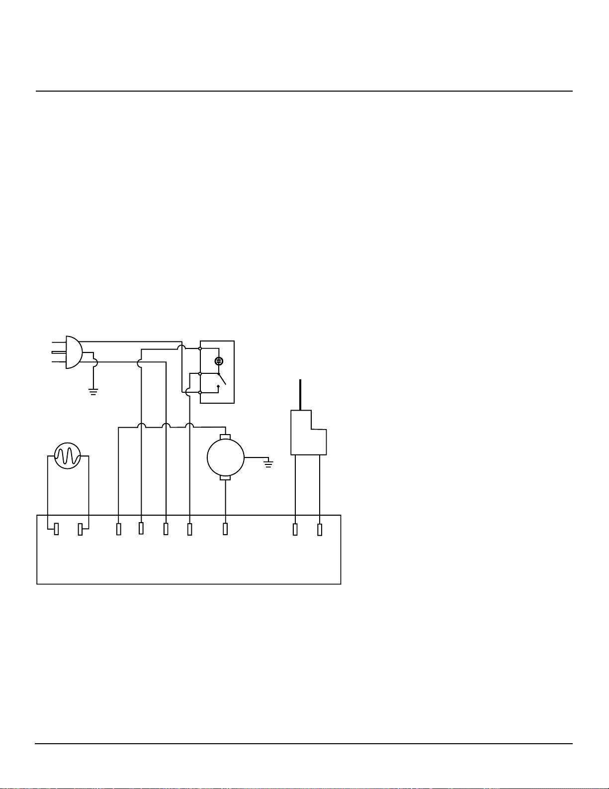
WIRING DIAGRAM
Power Plug
230 V/50Hz
Green-Yellow
Brown
Blue
1b
ON/Off Switch
1
Photocell
Blue
(2)(1)
White
Blue
(3) (4) (6)
White
(N)
Blue
(5)
Ignition Control
1a
Brown
Green-Yellow
Motor
Red
(7)
Ignitor
Black
(8)
Black
105398
23
Page 26

R
PORTABLE FORCED AIR HEATERS
ACCESSORIES
Purchase accessories from your local dealer.
AIR GAUGE KIT - HA1180
For all models. Special tool to check pump
pressure.
HEAVY DUTY WHEELS AND
HANDLE KIT - HA1202
For heavy duty applications. Makes your
heater even more portable and convenient.
For B35CEH and B70CEH models.
STANDARD WHEELS AND
HANDLE KIT - HA1206
Makes heater even more portable and convenient. Easy to assemble. For B35CEH
and B70CEH models.
A 008
IGNITION CONTROL
ASSEMBLY/PHOTOCELL
TESTER - HA1170
Special tool used to test the ignition control
assembly and photocell.
24
105398
Page 27

EC CONFORMITY
DECLARATION
Model Numbers: B35CEH, B70CEH, B100CEH, B150CEH
OWNER’S MANUAL
EC CONFORMITY DECLARATION
DESA Europe B.V.
Innsbruckweg 144, 3047 AH
Postbus 11158
3004 ED Rotterdam
Holland
Manufacturer:
DESA International, Inc.
2701 Industrial Drive
Bowling Green, KY 42101 U.S.A.
Kerosene Portable Forced Air Heaters
It is declared that these models conform to the Machinery Directive 98/37/EC,
including 91/368/EEC and the Low Voltage Directive 73/23/EEC. It is further
declared that these models conform to the EMC Directive 89/336/EEC, amended
by 92/31/EEC and including EN50081-1 and EN50082-1.
We declare that the models noted are in conformity.
Company DESA International, Inc.
Name Joseph B. Lee
Title Vice President, Heating Products Engineering
07/25/2000 — Bowling Green, KY
Date and Place Signature
105398
25
Page 28

WARRANTY INFORMATION
CERTIFICATE OF GENERAL
EQUIPMENT - LIMITED ONE YEAR WARRANTY
DESA International warrants new Products sold by it to be
free from defects in material or workmanship for a period of one
year after date of delivery to the first user and subject to the
following conditions:
DESA International's obligation and liability under this
Warranty is expressly limited to repairing or replacing at DESA
International's option, any parts which appear to DESA International upon inspection to have been defective in material or
workmanship when shipped from the factory. Such parts shall
be provided at no cost to the user, at the business establishment
of any factory authorized service center or the factory during
regular working hours. The Warranty shall not apply to component parts or accessories of Products not manufactured by
DESA International and which carry the warranty of the manufacturer thereof, or to normal maintenance (such as pressure
adjustments) or to normal maintenance parts (such as filters
and spark plugs). Replacement or repair parts installed in the
Product covered by this Warranty are warranted only for the
remainder of this Warranty as if such parts were original components of said Product. DESA INTERNATIONAL MAKES NO
OTHER EXPRESS WARRANTY. TO THE EXTENT PERMITTED BY LAW DESA INTERNATIONAL MAKES NO IMPLIED
WARRANTY AND MAKES NO WARRANTY OF MERCHANTABILITY OR FITNESS FOR ANY PARTICULAR PUR-
WARRANTY SERVICE
POSE. IN ANY EVENT IMPLIED WARRANTIES INCLUDING
THOSE OF MERCHANTABILITY AND FITNESS FOR A PARTICULAR PURPOSE ARE LIMITED TO THE DURATION OF
THIS EXPRESS WARRANTY.
Any transportation charges, costs of installation, duty,
taxes or any other charges whatsoever must be borne by the
user. DESA International's obligation under this limited Warranty shall not include any liability for direct, indirect, incidental,
or consequential damage or delay. If requested by DESA
International, Products or parts for which a warranty claim is
made are to be returned transportation prepaid by user to the
factory. Any improper use, including operation after discovery
of defective or worn parts, operation beyond capacity, substitution of parts not approved by DESA International, or any
alteration or repair by others in such manner as in DESA
International's judgement affects the Product materially and
adversely, shall void this Warranty.
NO EMPLOYEE OR REPRESENTATIVE IS AUTHORIZED
TO CHANGE THIS WARRANTY IN ANY WAY OR GRANT
ANY OTHER WARRANTY UNLESS SUCH CHANGE IS
MADE IN WRITING AND SIGNED BY AN OFFICER OF DESA
INTERNATIONAL AT ITS HOME OFFICE.
Always specify model and serial numbers when communicating
with the factory.
We reserve the right to amend these specifications at any time
without notice. The only Warranty applicable is our standard
written Warranty. We make no other Warranty, expressed or
implied.
A Service Manual is available by writing to the Technical Service
Department at:
Corporate Headquarters
2701 Industrial Drive
P.O. Box 90004
Bowling Green, Kentucky 42102-9004
U.S.A.
Printed in U.S.A.
Page 29
R
APPAREILS DE
CHAUFFAGE
INDIVIDUELS
À AIR FORCÉ
MANUEL D’UTILISATION
Production de la chaleur: 8 800, 17 500, 25 000, et 38 000 Kcal/h
Modèles: B35CEH, B70CEH, B100CEH, et B150CEH
IMPORTANT: Veiller à lire et comprendre ce manuel avant de monter,
mettre en marche ou effectuer l’entretien de cet appareil. Une mauvaise
utilisation de cet appareil pourrait causer des blessures graves. Conserver
ce manuel pour s’y reporter plus tard.
Page 30

R
APPAREILS DE CHAUFFAGE INDIVIDUELS À AIR FORCÉ
NOTES SUR
LA SÉCURITÉ
AVERTISSEMENTS
IMPORTANT: Veiller à lire ce
manuel d’utilisation attentivement et complètement avant de
tenter de monter, de faire fonctionner ou d’effectuer l’entretien
de cet appareil. Une mauvaise
utilisation de cet appareil de
chauffage peut causer des blessures graves voire la mort par
brûlures, incendie, explosion,
électrocution et intoxication par
l’oxyde de carbone.
DANGER: L’intoxication par
l’oxyde de carbone peut entraîner la mort!
Intoxication par l’oxyde de carbone: Les
premiers signes d’intoxication par l’oxyde de
carbone ressemblent à ceux de la grippe:
maux de tête, vertiges ou nausée. Si l’on
ressent ces symptômes, il se peut que l’appareil de chauffage ne fonctionne pas correctement. Aller immédiatement respirer de l’air
frais! Faire réparer l’appareil de chauffage.
Certaines personnes sont plus susceptibles
que d’autres aux effets de l’oxyde de carbone,
par exemple les femmes enceintes, les personnes souffrant de maladies cardiaques ou
pulmonaires, d’anémie, celles sous l’effet de
l’alcool ou celles se trouvant à haute altitude.
Veiller à lire et comprendre tous les avertissements. Conserver ce manuel pour s’y reporter plus tard. C’est un guide pour l’utilisation correcte et sans danger de cet appareil
de chauffage.
• Ne se servir que de kérosène ou de fioul
n˚1 pour éviter les risques d’incendie
ou d’explosion. Ne jamais utiliser d’essence, de naphte, de diluants à peinture,
d’alcool ou d’autres combustibles hautement inflammables.
• Alimentation en carburant
a) Les employés chargés de refaire le
plein doivent être qualifiés et doivent
bien connaître les instructions du fabricant et la réglementation applicable concernant l’alimentation sûre en
carburant des appareils de chauffage.
b)Seul le type de carburant précisé sur
la plaque signalétique de l’appareil
de chauffage doit être utilisé.
c)Avant de refaire le plein, il faut s’as-
surer que toutes les flammes, y compris la veilleuse, le cas échéant, sont
éteintes et que l’appareil de chauffage a refroidi.
d)Durant l’alimentation en carburant,
il importe d’inspecter toutes les conduites de carburant et tous les raccords de conduite de carburant pour
y relever d’éventuelles fuites. Toutes les fuites doivent être corrigées
avant de remettre l’appareil de chauffage en service.
e)On ne doit jamais stocker plus d’un
jour d’approvisionnement en carburant pour l’appareil de chauffage à
l’intérieur d’un bâtiment, à proximité
de l’appareil de chauffage. Le carburant en vrac doit être stocké à l’extérieur de la structure.
f) Tout le carburant doit être stocké à
une distance d’au moins 762 cm (25
feet) des appareils de chauffage, chalumeaux, matériel de soudage et
sources similaires d’inflammation
(exception faite du réservoir de carburant faisant partie intégrante de
l’appareil de chauffage).
g)Le carburant doit, autant que possi-
ble, être stocké là où les pénétrations
du plancher ne permettent pas que le
carburant s’égoutte sur un feu situé
plus bas ou soit allumé par ce feu.
h)Le carburant doit être stocké confor-
mément à toutes les réglementations
applicables.
• Ne jamais se servir de l’appareil dans
des endroits contenant des vapeurs
d’essence, de diluant à peinture ou
d’autres vapeurs hautement inflammables.
• Se conformer à tous les règlements et
codes locaux lors de l’utilisation de
l’appareil.
• Ne le faire fonctionner que dans des endroits bien aérés. Assurer au moins
2800 cm2 (3 sq ft) d’air frais extérieur
pour chaque 25 000 Kcal/h (100 000
BTU Hr) de rendement nominal.
• Ne le faire fonctionner que dans des endroits sans vapeurs inflammables et
sans poussière.
• Ne le brancher que sur du courant des
tension et fréquence spécifiées sur la
plaque signalétique.
• Ne se servir que d’une rallonge à trois
fils avec mise à la terre.
• Les appareils de chauffage utilisés à
proximité de bâches, de toiles ou de matériaux similaires d’enceinte doivent
être placés à une distance sûre de ces
matériaux. La distance sûre minimale
recommandée est de 304,8 cm (10 feet).
Il est également recommandé que ces
matériaux d’enceinte soient de nature
ignifuge. Ces matériaux d’enceinte
doivent être fixés solidement pour les
empêcher de s’enflammer ou de renverser l’appareil de chauffage sous l’action du vent.
• LB Distance minimale entre l’appareil
et tout matériau combustible:
Sortie : 250 cm (8 ft.)
Côtés, dessus et arrière: 125 cm (4 ft.)
• Placer l’appareil de chauffage sur une
surface stable et horizontale lorsqu’il
est chaud ou en marche pour éviter de
provoquer un incendie.
• Lors du déplacement ou du remisage
de l’appareil, le maintenir horizontal
pour éviter de renverser du carburant.
• Maintenir enfants et animaux éloignés
de l’appareil de chauffage.
• Débrancher l’appareil lorsqu’on ne s’en
sert pas.
• S’il est muni d’un thermostat, l’appareil peut se mettre en marche à n’importe quel moment.
• Ne jamais utiliser l’appareil dans les
salles de séjour ou dans les chambres à
coucher.
• Ne jamais bloquer l’entrée d’air (arrière) ou la sortie d’air (avant) de l’appareil.
• Ne jamais déplacer, manipuler , faire le
plein ou effectuer l’entretien d’un appareil chaud, en marche ou branché.
• Ne jamais monter de canalisation de
distribution d’air àl’avant ou à l’arrière
de l’appareil.
2
105398
Page 31

MANUEL D’UTILISATION
NOMENCLATURE
DES PIÈCES
Sortie d’air
chaud
Couvercle
Boîtier
Réservoir de
carburant
Panneau latéral
Lumière de ON/OFF
Figure 1 - Modèles B35CEH et B70CEH
Sortie d’air
chaud
Boîtier
Bouchon
du réservoir
de carburant
Poignée
Couvercle
Grille de protection
du ventilateur
Cache-filtre
Bouchon du
réservoir de
carburant
Cordon
électrique
Grille de
protection
du ventilateur
DÉBALLAGE
1. Retirer tous les emballages de protection utilisés pour le transport.
2. Retirer tous les éléments contenus dans
la boîte.
3. Vérifier s’ils ont été endommagés pendant le transport. Si l’appareil est endommagé, avertir au plus tôt le concessionnaire qui l’a vendu.
CARBURANTS
AVERTISSEMENT: Ne se servir que de kérosène ou de fioul
n˚1 pour éviter les risques d’incendie ou d’explosion. Ne jamais
utiliser d’essence, de naphte, de
diluants à peinture, d’alcool ou
d’autres combustibles hautement
inflammables.
Ne pas se servir de carburants lourds tels
que le fioul n˚2 ou le carburant diesel n˚2.
L’utilisation de carburants lourds peut donner lieu:
• au colmatage du filtre à carburant et du
gicleur
• au besoin d’ajouter au carburant des produits antigel non toxiques durant les périodes de grand froid.
IMPORTANT:
EXCLUSIVEMENT pour du KÉROSÈNE.
S’assurer que le récipient de stockage est
propre. Les matières étrangères telles que la
rouille, la poussière ou l’eau provoquent
l’arrêt de l’appareil par le détecteur d’extinction de flamme. En outre, elles peuvent
exiger un nettoyage plus fréquent du circuit
d’alimentation en carburant.
Se servir d’un bidon utilisé
Panneau
latéral
Figure 2 - Modèles B100CEH et B150CEH
105398
Lumière de
ON/OFF
Réservoir
de carburant
Cordon
électrique
3
Page 32

R
APPAREILS DE CHAUFFAGE INDIVIDUELS À AIR FORCÉ
MONTAGE
(POUR MODÈLES B100CEH
ET B150CEH)
Ces modèles sont livrés avec des roues et des
guidons. Ces derniers et leur boulonnerie de
montage se trouvent dans la boîte d’expédition.
Outils Nécessaires
• T ournevis cruciforme de taille moyenne
• Clé plate ou à molette de 3/8 po
• Marteau
1. Faire passer l’essieu dans le berceau.
Installer les roues sur l’essieu.
IMPORTANT:
le côté allongé du moyeu tourné vers
le berceau (voir figure 3).
Sortie d’air
chaud
Rebord du
réservoir de
carburant
Berceau
Roue
Installer les roues avec
Vis
Écrou
2. Placer les écrous borgnes sur les extrémités de l’essieu. T aper légèrement
dessus avec le marteau pour les mettre en place.
3. Placer l’appareil de chauffage sur le
berceau. S’assurer que le côté entrée
d’air (arrière) de l’appareil se trouve
au-dessus des roues. Aligner les trous
du rebord du réservoir de carburant
avec les trous du berceau.
4. Placer les guidons avant et arrière sur
le rebord du réservoir de carburant.
Faire passer les vis à travers les guidons, le rebord du réservoir et le berceau. Ceci fait, serrer à la main un écrou
sur chaque vis.
Guidon
avant
Guidon
arrière
Entrée
d’air
5. Une fois toutes les vis en place, serrer
fermement les écrous.
6. Leg het heteluchtkanon op het onderstel. Zorg dat de luchtinlaatopening
(achterkant) zich boven de wielen bevindt. Breng de gaten in de rand rond
de brandstoftank in lijn met de gaten
in het onderstel.
7. Plaats de voorste en achterste hendel
op de rand rond de tank. Steek de
schroeven door de hendels, de rand
rond de tank en het onderstel. Bevestig
na het aanbrengen van iedere schroef
een moer; draai deze met de hand vast.
8. Draai alle moeren stevig vast nadat alle
schroeven zijn aangebracht.
VENTILATION
AVERTISSEMENT: Respecter les règles minimales de ventilation en air frais extérieur. Sans
ventilation adéquate en air frais
extérieur, il y a risque d’intoxication par l’oxyde de carbone. S’assurer que ces règles sont bien
suivies avant de faire fonctionner l’appareil de chauffage.
Assurer l’entrée d’air frais extérieur par une
ouverture d’au moins 2800 cm
(3 sq ft) pour chaque 25 000 Kcal/h (100 000
Btu/Hr) de rendement nominal. Prévoir davantage d’air frais si plusieurs appareils
sont utilisés.
Exemple:
38 000 Kcal/h (150 000 Btu/Hr) doit fonctionner dans l’une des conditions suivantes:
• une porte double de garage relevée de 15
cm (6 po)
• une porte simple de garage relevée de 23
cm (9 po)
• deux fenêtres à guillotine de 76 cm (30
po) de large relevées de 31 cm (12 po)
Un appareil de chauffage de
2
Écrou
borgne
Figure 3 - Montage des roues et des guidons
Essieu
Moyeu
allongé
4
105398
Page 33

MANUEL D’UTILISATION
PRINCIPES DE
FONCTIONNEMENT
Circuit d’alimentation en carburant: La
pompe à air force l’air dans la conduite
d’air. L’air passe ensuite par le gicleur du
brûleur. La dépression causée par l’air fait
monter le carburant du réservoir. Un fin
nuage de carburant est vaporisé dans la
chambre de combustion.
Circuit d’air: Le moteur fait tourner le ven-
tilateur. Celui-ci pousse l’air dans et autour
de la chambre de combustion. Cet air est
chauffé et produit un jet d’air chaud non
pollué.
Dispositif d’allumage : La commande d’al-
lumage envoie le courant à l’allumeur. Celui-ci enflamme le mélange combustible/air
dans la chambre de combustion.
Détecteur d’extinction de flamme: Ce dis-
positif arrête l’appareil de chauffage si la
flamme s’éteint.
Chambre de
combustion
Allumeur
FONCTIONNEMENT
AVERTISSEMENT: Veiller à
revoir et à bien comprendre les
avertissements qui se trouvent
dans la section “Notes sur la sécurité”, page 2. Cela est nécessaire
pour faire fonctionner cet appareil
en toute sécurité. Respecter tous
les règlements locaux lors de l’utilisation de cet appareil.
MISE EN MARCHE DE
L’APPAREIL
1. Suivre les instructions concernant la
ventilation et la sécurité.
2. Faire le plein du réservoir avec du kérosène ou du fioul n˚1.
3. Remettre le bouchon du réservoir.
4. Brancher le cordon électrique de l’appareil dans une prise standard de 230
Volt et 50 Hz avec prise de terre. Se
servir d’une rallonge si nécessaire.
N’utiliser qu’une rallonge à trois fils
avec mise à la terre.
Moteur
Ventilateur
Pompe à air
Filtre à air
d’entrée
CONDITIONS REQUISES
POUR LES RALLONGES
ÉLECTRIQUES
Pour des longueurs atteignant 30,5 m (100
ft), rallonge de calibre 1,0 mm
(16 AWG)
De 30,6 à 61 m (101 à 200 ft), rallonge de
calibre 1,5 mm2 (14 AWG)
Mettre l’interrupteur MARCHE/ARRÊT en
position de MARCHE (|) et l’appareil doit
se mettre en marche dans les 5 secondes. Si
ce n’est pas le cas, voir Dépannage (page 7
et 8).
POUR ARRÊTER
L’APPAREIL DE CHAUFFAGE
Mettre l’interrupteur MARCHE/ARRÊT en
position d’ARRÊT (O).
POUR REMETTRE
L’APPAREIL EN MARCHE
1. Mettre l’interrupteur MARCHE/ARRÊT en position d’ARRÊT (0) et attendre 10 secondes (2 minutes si l’appareil a fonctionné).
2. Répéter les opérations indiquées page
5 sous la rubrique Mise en marche de
L’appareil.
2
Sortie
d’air
chaud
non
pollué
Réservoir
de carburant
Figure 4 - Coupe, fonctionnement
105398
Gicleur
Air de
combustion
Filtre à
carburant
Air de combustion
et de chauffage
Conduite
d’air vers
brûleur
|
Lumière de ON/OFF
Entrée
d’air
frais
Filtre
à air
de
sortie
Figure 5 - Interrupteur MARCHE/ARRÊT,
Modèles B35CEH et B70CEH
Allumeur
électronique
Carburant
Figure 6 - Interrupteur MARCHE/ARRÊT,
Modèles B100CEH et B150CEH
5
O
Lumière de ON/OFF
|
O
Page 34

R
APPAREILS DE CHAUFFAGE INDIVIDUELS À AIR FORCÉ
ENTREPOSAGE,
TRANSPORT OU
EXPÉDITION
Remarque:
gent que les réservoirs de combustible soient
vides pour l’expédition.
1. Vidanger le réservoir de combustible.
Remarque:
pés d’un bouchon de vidange au-dessous
du réservoir. Le cas échéant, le retirer pour
vidanger le réservoir. Si l’appareil de
chauffage n’en est pas équipé, vidanger
le réservoir par l’orifice de remplissage.
V eiller à vider complètement le réservoir .
2. Le cas échéant, replacer le bouchon de
vidange.
3. Si le vieux carburant contient des impuretés, ajouter 1 ou 2 litres de kérosène
propre, remuer et vidanger à nouveau afin
d’éviter que l’accumulation d’impuretés
n’obstrue les filtres lors d’un futur usage.
4. Remettre le bouchon de vidange ou de
remplissage. Mettre le vieux carburant
sale au rebut selon une méthode appropriée. Se renseigner auprès d’une station-service locale qui recycle l’huile.
5. Entreposer l’appareil de chauffage dans
un endroit sec, à l’abri de la poussière
et des vapeurs corrosives.
IMPORTANT:
sène pour la durée de l’été en vue de l’utiliser la saison suivante. L’usage de combustible défraîchi pourrait endommager l’appareil de chauffage.
les sociétés de transport exi-
certains modèles sont équi-
ne pas entreposer le kéro-
TABLEAU
D’ENTRETIEN
PRÉVENTIF
Élemént
Réservoir de carburant
Filtres de sortie d’air
et à peluche
Filtre d’entrée d’air
Filtre à carburant
Allumeur
Pales du ventilateur
Moteur
Périodicité
Rincer toutes les 150 à 200
heures de fonctionnement ou
selon le besoin
Remplacer toutes les 500 heures de fonctionnement ou une
fois par an
Le laver à l’eau savonneuse et
le sécher toutes les 500 heures
de fonctionnement ou selon le
besoin
Le nettoyer deux fois par période de chauffage ou selon le
besoin
Aucun entretien requis
Les nettoyer chaque saison ou
selon le besoin
Aucun entretien nécessaire.
Lubrification permanente
AVERTISSEMENT: Ne jamais effectuer l’entretien de l’appareil de chauffage s’il est branché, en marche ou
chaud. Cela peut entraîner des brûlures
graves ou l’électrocution.
Opération
Voir Entreposage, Transport ou
Expédition ci-dessus
Voir Filtres de sortie d’air, d’entrée d’air et à peluche, page 11
Voir Filtres de sortie d’air, d’entrée d’air et à peluche, page 11
Voir Filtre à carburant, page 9
Voir Ventilateur, page 14
6
105398
Page 35

MANUEL D’UTILISATION
DÉPANNAGE
AVERTISSEMENT: Ne jamais effectuer l’entretien de l’appareil de
chauffage s’il est branché, en marche ou chaud. Cela peut entraîner des
brûlures graves ou l’électrocution.
RADIATEUR À ASSEMBLAGE DE COMMANDE D’ALLUMAGE AVEC OU SANS FUSIBLE
ANOMALIE OBSERVÉE
Le moteur ne démarre pas dans les cinq
secondes après le branchement de l’appareil
de chauffage
(Lumière ON/OFF demeure allumée)
Le moteur démarre et tourne, mais l’appareil ne s’allume pas
(Lumière ON/OFF demeure allumée)
CAUSE PROBABLE
1. Mauvaise connexion électrique entre le
moteur et la commande d’allumage ou
entre la commande d’allumage et le cordon électrique
AVERTISSEMENT: Haute tension!
2. Grippage du rotor de la pompe
3. Commande d’allumage défectueuse
4. Moteur défectueux
1. Pas de combustible dans le réservoir
2. Pression incorrecte de la pompe
3. Filtre à combustible encrassé
4. Gicleur obstrué
5. Eau dans le réservoir de combustible
REMÈDE
1. Vérifier tous les branchements électriques. Voir Schéma électrique, page 15
2. Si le ventilateur tourne avec difficulté,
voir Rotor de la pompe, page 15
3. Remplacer la commande d’allumage
4. Remplacer le moteur
1. Remplir le réservoir avec du kérosène
2. Voir Réglage de la pression de la
pompe, page 11
3. Voir Filtre à carburant, page 9
4. Voir Gicleur, page 12
5. Vidanger et rincer le réservoir de combustible avec du kérosène propre. Voir
Entreposage, transport ou expédition,
page 6
L’appareil s’allume mais la commande d’allumage l’arrête après quelques instants
(Lumière ON/OFF demeure allumée)
AVERTISSEMENT: Haute tension!
6. Mauvaise connexion électrique entre
l’allumeur et la commande d’allumage
7. Allumeur défectueux
8. Commande d’allumage défectueuse
1. Pression incorrecte de la pompe
2. Filtres d’entrée d’air, de sortie d’air ou
à peluche encrassés
3. Filtre à combustible sale
4. Gicleur obstrué
5. Cellule photoélectrique mal installée (ne
voit pas la flamme)
AVERTISSEMENT: Haute tension!
6. Lentille de cellule photoélectrique sale
7. Mauvaise connexion électrique entre la
cellule photoélectrique et la commande
d’allumage
8. Cellule photoélectrique défectueuse
9. Commande d’allumage défectueuse
6. Vérifier les connexions électriques. V oir
Schéma électrique, page 15
7. Remplacer l’allumeur, voir page 10
8. Remplacer la commande d’allumage
1. Voir Réglage de la pression de la
pompe, page 11
2. Voir Filtres de sortie d’air, d’entrée
d’air et à peluche, page 11
3. Voir Filtre à carburant, page 9
4. Voir Gicleur, page 12
5. S’assurer que l’enveloppe de la cellule
photoélectrique est bien logée dans le
support
6. Nettoyer la lentille de la cellule photoélectrique
7. Vérifier les connexions électriques. V oir
Schéma électrique, page 15
8. Remplacer la cellule photoélectrique
9. Remplacer la commande d’allumage
105398
Voir Page Suivante
7
Page 36

R
APPAREILS DE CHAUFFAGE INDIVIDUELS À AIR FORCÉ
DÉPANNAGE
Suite
RADIATEUR À ASSEMBLAGE DE COMMANDE D’ALLUMAGE SANS FUSIBLE SEULEMENT
ATTENTION:
OFF pour dépister la condition de défaut.
Le réglage d’allumage à été construit avec une protection intégrée contre les surcharges. Servez-vous de la lumière de ON/
ANOMALIE OBSERVÉE
La lumière de ON/OFF ne s’allume pas
lorsque le commutateur est mis à la position
ON (|) et le radiateur ne fonctionne pas
La lumière de ON/OFF s’allume lorsque le
commutateur est mis à la position ON (|)
mais elle s’éteint après cinq secondes
CAUSE PROBABLE
1. Aucun courant au radiateur
AVERTISSEMENT: Haute tension!
2. Mauvaises connexions électriques
3. Court-circuit dans l’allumeur
1. Court-circuit au moteur
AVERTISSEMENT: Haute tension!
REMÈDE
1. S’assurer que le cordon électrique est
branché sur une prise de courant et que
coupe-circuit du panneau électrique est
remis à l’état initial
2. Vérifier le câblage électrique et les
connexions. Voir schéma de câblage,
page 15
3. Vérifier la câblage de l’allumeur. En
l’absence de problème, remplacer l’allumeur (voir page 10)
1. Vérifier le câblage du moteur. En
l’absence de problème, remplacer le
moteur
8
105398
Page 37

MANUEL D’UTILISATION
PROCÉDURES
D’ENTRETIEN
AVERTISSEMENT: Ne jamais
effectuer l’entretien de l’appareil
de chauffage s’il est branché, en
marche ou chaud. Cela peut entraîner des brûlures graves ou
l’électrocution.
DÉPOSE DU COUVERCLE
1. Enlever les vis se trouvant de chaque
côté de l’appareil àl’aide d’une clé à
douille de 5/16 po. Ces vis retiennent
le couvercle sur le boîtier.
2. Enlever le couvercle.
3. Retirer la grille de protection du ventilateur.
FILTRE À CARBURANT
(Modèles B35CEH et B70CEH)
1. Retirer les vis du panneau latéral à
l’aide d’une clé à douille de 5/16 po.
2. Déposer le panneau latéral.
3. Détacher la conduite de carburant en
caoutchouc de l’embase du filtre à carburant.
4. Soulever avec précaution la bague et
le filtre à carburant hors du réservoir
de carburant.
5. Laver le filtre à carburant avec du carburant propre et le remettre dans le réservoir.
6. Brancher la conduite de carburant en
caoutchouc sur l’embase du filtre à carburant.
7. Remonter le panneau latéral.
FILTRE À CARBURANT
(Modèles B100CEH et B150CEH)
1. Retirer les vis du couvercle latéral à
l’aide d’une clé àdouille de 5/16 po.
2. Enlever le couvercle latéral.
3. Sortir la conduite de carburant supérieure du goulot du filtre à carburant.
4. A vec précaution, dégager le manchon,
la conduite à carburant inférieure et le
filtre à carburant du réservoir.
5. Nettoyer le filtre avec du carburant propre et le replacer dans le réservoir.
6. Rebrancher la conduite à carburant supérieure sur le goulot du filtre.
7. Remonter le couvercle latéral.
Couvercle
Figure 7 - Dépose du couvercle, Modèles
B35CEH et B70CEH
Filtre à carburant
Panneau
latéral
Figure 9 - Dépose du filtre à carburant, Modèles B35CEH et B70CEH
Filtre à carburant,
manchon et
conduite à carburant inférieure
Panneau
latéral
Figure 10 - Dépose du filtre à carburant, Modèles B100CEH et B150CEH
Grille de
protection du
ventilateur
Figure 8 - Dépose du couvercle, Modèles
B100CEH et B150CEH
Conduite de
carburant
Couvercle
Conduite à
carburant
supérieure
Voir Page Suivante
Grille de
protection du
ventilateur
105398
9
Page 38

R
APPAREILS DE CHAUFFAGE INDIVIDUELS À AIR FORCÉ
PROCÉDURES
D’ENTRETIEN
Suite
ALLUMEUR
1. Retirer le couvercle et la grille de protection du ventilateur (voir page 9).
2. Retirer le ventilateur (voir page 14).
3. Enlever les 4 vis du panneau latéral à
l’aide d’une clé à douille de 5/16 po.
Déposer le panneau latéral. (voir figure
9 ou 10, page 9).
4. Débrancher les fils de l’allumeur (noir)
de la commande d’allumage (voir figure 11). T irer les fils de l’allumeur vers
le haut par le trou du boîtier.
5. Débrancher les flexibles des conduites
de combustible et d’air. Enlever la cellule photoélectrique de son support
(voir figure 11).
Chambre de
combustion
Support
d’adaptateur
de gicleur
6. Retirer la chambre de combustion. Dresser la chambre de combustion sur une
extrémité avec le support de l’adaptateur du gicleur en haut (voir figure 12).
7. Enlever la vis de l’allumeur avec une
clé à douille de 1/4 po. Avec précaution, retirer l’allumeur du support de
l’adaptateur du gicleur.
ATTENTION: Éviter de plier
ou de heurter l’élément allumeur.
Le manipuler avec précaution.
8. A vec précaution, enlever l’allumeur de
rechange de l’emballage en
styromousse.
9. Avec précaution, guider l’allumeur
dans l’ouverture du support de l’adaptateur de gicleur. Éviter de heurter l’élément allumeur. Fixer l’allumeur au support de l’adaptateur de gicleur avec une
vis à l’aide d’une clé à douille de 1/4
po (voir figure 12). Serrer de 0,90 N.m
à 1,69 Nm (8 à 15 lb-po) sans excès.
10. Remonter la chambre de combustion.
11. Ramener les fils de l’allumeur vers le
bas par le trou du boîtier. Brancher les
fils à la commande d’allumage.
12. Remonter le panneau latéral. (Voir figure 9 ou 10, page 9).
13. Raccorder et acheminer les flexibles
des conduites de combustible et d’air
au brûleur. V oir Remplacement et ache-
minement correct des conduites de
combustible et d’air, page 12.
14. Remettre la cellule photoélectrique
dans son support. Acheminer les fils
comme illustré à la figure 17, 18 ou 19,
page 12.
15. Remonter le ventilateur (voir page 14).
16. Remonter la grille de protection du ventilateur et le couvercle (voir page 9).
Flexible de
conduite de
combustible
Flexible de
conduite
d’air
Support de
cellule photoé-
lectrique
Cellule
photoélectrique
Panneau latéral
Figure 11 - Débranchement des fils d’al-
lumeur de la commande d’allumage
Allumeur
Fils
d’allumeur
Commande
d’allumage
Ensemble vis/rondelle
d’allumeur
Élément
allumeur
Support de cellule
photoélectrique
Chambre de
combustion
Figure 12 - Remplacement de l’allumeur
Ouverture de support
d’adaptateur de gicleur
Allumeur
Support
d’adaptateur
de gicleur
10
105398
Page 39

MANUEL D’UTILISATION
PROCÉDURES
D’ENTRETIEN
Suite
FILTRES DE SORTIE D’AIR,
D’ENTRÉE D’AIR ET À
PELUCHE
1. Déposer le couvercle (voir page 9).
2. Retirer les vis du cache-filtre à l’aide
d’une clé à douille de 5/16 po.
3. Déposer le cache-filtre.
4. Remplacer les filtres de sortie d’air et
à peluche.
5. Laver ou remplacer le filtre d’entrée
d’air (voir T ableau d’entr etien préven-
tif page 6).
6. Remonter le cache-filtre.
7. Remonter la grille de protection du ventilateur et le couvercle.
IMPORTANT:
RÉGLAGE DE LA PRESSION
DE LA POMPE
1. Retirer le bouchon du trou du manomètre du cache-filtre.
2. Installer le manomètre (numéro de
pièce HA1180).
3. Mettre l’appareil en marche (voir Fonc-
tionnement page 5). Attendre que le
moteur atteigne son régime maximum.
4. Régler la pression Tourner le clapet de
décharge vers la droite pour augmenter
la pression et vers la gauche Consulter les
spécifications ci-contre pour déterminer
la pression requise par chaque modèle.
5. Retirer le manomètre et remettre le bouchon du trou du manomètre sur le
cache-filtre.
Ne pas huiler les filtres.
Filtre d’entrée d’air
Cache-filtre
Filtre à
peluche
Figure 13 - Filtres de sortie d’air, d’entrée d’air et àpeluche, Modèles B35CEH et
B70CEH
Filtre à
peluche
Figure 14 - Filtres de sortie d’air, d’entrée d’air et àpeluche, Modèles B100CEH et
B150CEH
Bouchon de
manomètre
Filtre de
sortie d’air
Filtre d’entrée d’air
Cache-filtre
Filtre de
sortie d’air
Modèlle de la pompe
B35CEH 0,200 bar
B70CEH 0,338 bar
B100CEH 0,338 bar
B150CEH 0,380 bar
Grille de protection
du ventilateur
Grille de protection du ventilateur
Pression
105398
Chapeau en
plastique
Figure 15 - Dépose du bouchon du trou
du manomètre
(Modèles B35CEH et B70CEH illustré)
11
Soupape
de sécurité
Manomètre
Figure 16 - Réglage de la pression de la
pompe
Voir Page Suivante
Page 40
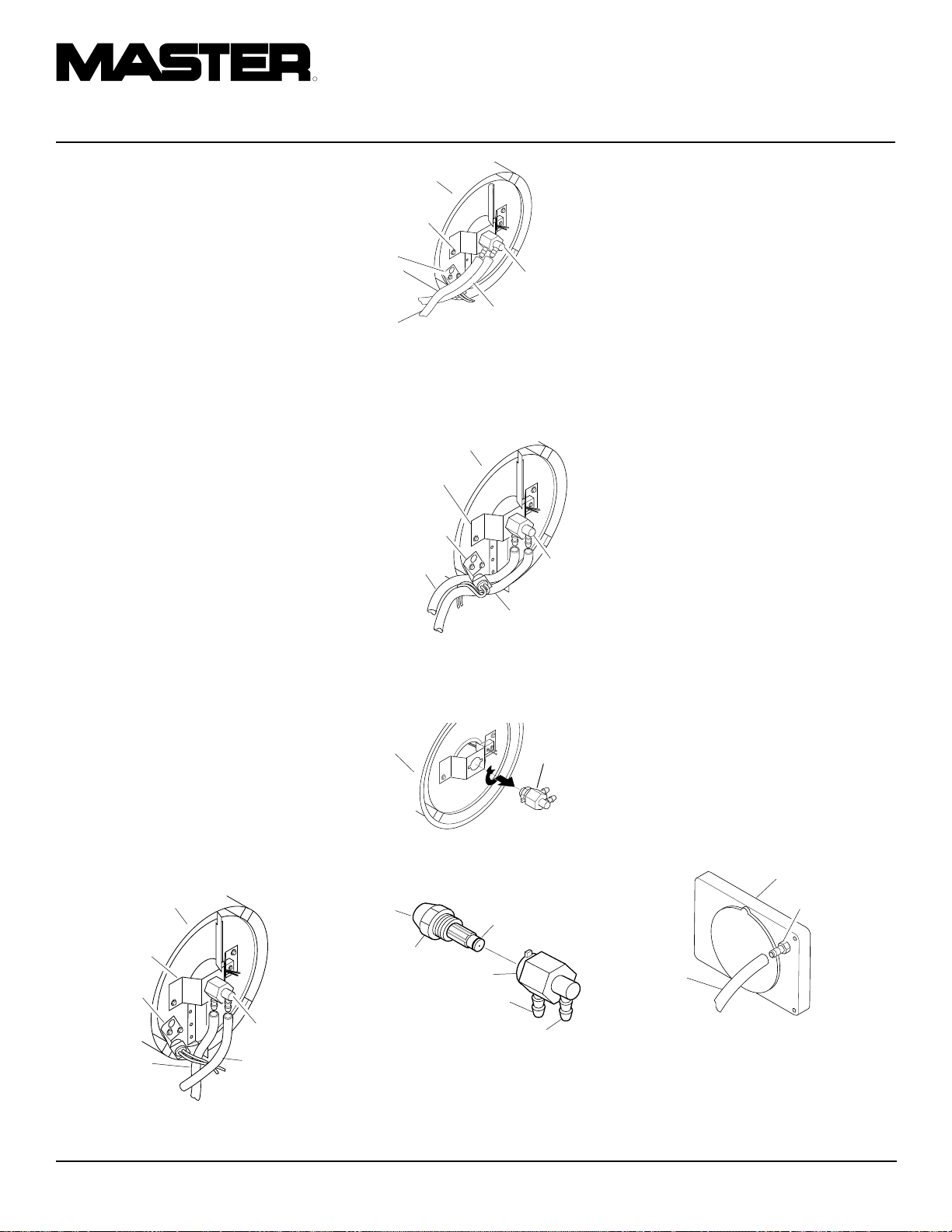
R
APPAREILS DE CHAUFFAGE INDIVIDUELS À AIR FORCÉ
PROCÉDURES
D’ENTRETIEN
Suite
GICLEUR
1. Retirer le couvercle (voir page 9).
2. Retirer le ventilateur (voir page 14).
3. Enlever les flexibles des conduites de
combustible et d’air du gicleur (voir figure 17, 18 ou 19).
4. Tourner le gicleur d’un quart de tour
vers la gauche et le tirer vers le moteur
pour l’enlever (voir figure 20).
5. Placer le corps hexagonal en plastique
dans un étau et serrer légèrement.
6. Avec précaution, retirer le gicleur de
son adaptateur à l’aide d’une clé à
douille de 5/8 po (voir figure 21).
7. Souffler de l’air comprimé au travers
du gicleur par l’avant pour éliminer toutes les impuretés.
8. Vérifier que le joint du gicleur n’est
pas endommagé.
9. Replacer le gicleur dans son adaptateur en
veillant à ce qu’il soit bien en place. Serrer
d’un tiers de tour supplémentaire à l’aide
d’une clé à douille de 5/8 po de 4,5 à 5,1
Nm (40 à 45 po-lb). Voir figure 21.
10. Remonter l’ensemble de gicleur sur la
bride de montage de brûleur.
11. Raccorder les flexibles des conduites de
combustible et d’air au gicleur. V oir Rem-
placement et acheminement correct des
conduites de combustible et d’air.
12. Remonter le ventilateur (voir page 14).
13. Remonter la grille de protection du ventilateur et le couvercle (voir page 9).
Chambre de
combustion
Support d’adapta-
teur de gicleur
Support de
cellule photoé-
lectrique
Tuyau d’air
Ensemble
gicleur/
adapteur
Tuyau de
carburant
Chambre de
combustion
Support
d’adaptateur
de gicleur
Tuyau d’air
Support de cellule
photoélectrique
Figure 18 - Dépose des flexibles des conduites de combustible et d’air (Modèle
B100CEH uniquement)
Chambre de combustion
Support d’adaptateur
de gicleur
Support de cellule
photoélectrique
Tuyau d’air
Tuyau de carburant
Figure 19 - Dépose des flexibles des conduites de combustible et d’air (Modèle
B150CEH uniquement)
Chambre de
combustion
Figure 20 - Dépose de l'ensemble gicleuradaptateur
Devant du
gicleur
Gicleur
Adaptateur
Raccord d’air
Raccord de carburant
Figure 21 - Gicleur et son adaptateur
Joint du gicleur
Ensemble
gicleur/
adapteur
Tuyau de
carburant
Ensemble
gicleur/
adapteur
Ensemble
gicleur/
adapteur
REMPLACEMENT ET
ACHEMINEMENT CORRECT
DES CONDUITES DE
COMBUSTIBLE ET D’AIR
1. Retirer le couvercle (voir page 9).
2. Enlever les vis du panneau latéral à
l’aide d’une clé à douille de 5/16 po.
3. Déposer le panneau latéral.
4. Vérifier que les flexibles des conduites
de combustible et d’air ne sont ni fendillés ni troués. Si le flexible de combustible est endommagé, le débrancher
de l’adaptateur de gicleur (voir figure
17, 18 ou 19) et du filtre à combustible
(voir page 9). Si le flexible d’air est endommagé, le débrancher de l’adaptateur de gicleur (voir figure 17, 18 ou 19)
et du raccord à griffes du couvercle d’extrémité de la pompe (voir figure 22).
5. Installer une conduite d’air et/ou de combustible neuve. Raccorder une extrémité
du flexible d’air au raccord à griffes du
couvercle d’extrémité de la pompe (voir
figure 22) et l’autre à l’adaptateur de
gicleur (voir figure 17, 18 ou 19). Raccorder une extrémité du flexible de combustible au filtre à combustible (voir
page 9) et l’autre à l’adaptateur de gicleur (voir figure 17, 18 ou 19).
Pour les modèles B35CEH et B70CEH,
acheminer les conduites de combustible et d’air à peu près comme illustré à
la figure 17.
Remarque:
pas toucher le support de la cellule photoélectrique.
Flexible
d’air
Figure 22 - Flexible d’air au raccord à
griffes
Les flexibles ne doivent
Couvercle d’extrémité
de pompe
Raccord à
griffes
Figure 17 - Dépose des flexibles des conduites de combustible et d’air (modèles
B35CEH et B70CEH uniquement)
12
105398
Page 41

MANUEL D’UTILISATION
PROCÉDURES
D’ENTRETIEN
Suite
Pour le modèle B100CEH, acheminer les
conduites de combustible et d’air à peu près
comme illustré à la figure 18, page 12.
Remarque :
pas toucher le support de la cellule photoélectrique.
Pour le modèle B150CEH, acheminer les
conduites de combustible et d’air à peu près
comme illustré à la figure 19, page 12.
Remarque :
pas toucher le support de la cellule photoélectrique.
6. Remonter le panneau latéral.
7. Remonter le couvercle et la grille de
protection du ventilateur (voir page 9).
ROTOR DE LA POMPE
(Procédure en cas de grippage)
1. Déposer le couvercle (voir page 9).
2. Retirer les vis du cache-filtre à l’aide
d’une clé à douille de 5/16 po.
3. Déposer le cache-filtre et les filtres à air.
4. Retirer les vis de la plaque de la pompe
à l’aide d’une clé àdouille de 5/16 po.
5. Déposer la plaque de la pompe.
6. Enlever rotor, pièce encastrée et pales.
7. Vérifier s’il y a des corps étrangers dans
la pompe. S’il y en a, les chasser à l’air
comprimé.
8. Installer la pièce encastrée et le rotor.
9. Vérifier le dégagement du rotor. Si nécessaire, le régler de 0,076 à 0,101 mm
(,003 à ,004 po) (voir figure 25).
Les flexibles ne doivent
Les flexibles ne doivent
Remarque :
Faire faire un tour complet au
Vis de réglage de l’écart
moteur pour s’assurer que l’écart à l’endroit
le plus serré est de 0,076 à 0,101 mm (,003
à ,004 po). Refaire le réglage si nécessaire.
10. Remonter pales, plaque de pompe, filtres à air et cache-filtre.
11. Remonter la grille de protection et le
couvercle.
12. Régler la pression de la pompe (voir
page 11).
Remarque :
Si le rotor est toujours grippé,
procéder comme suit.
Vis de réglage de l’écart
Figure 25 - Emplacement des vis de ré-
glage de l’écart
Rotor
13. Effectuer les opérations 1 à 6 ci-dessus.
14. Placer une feuille de papier de verre fin
(600) sur une surface plate. Poncer légèrement le rotor sur la feuille d’un
mouvement en forme de “8” (voir figure 26). Répéter quatre fois.
15. Remonter la pièce encastrée et le rotor.
Figure 26 - Ponçage du rotor
16. Effectuer les opérations 10 à 12
ci-dessus.
Pale
Pièce
encastrée
Rotor
Filtre d’arrivée
d’air
Figure 24 - Emplacement du rotor, Modèles B100CEH et B150CEH
Plague de pompe
Filtre d’entrée d’air
Cache-filtre
Grille de
protection du
ventilateur
Écart de 0,076
à 0,101 mm
(,003 à ,004 po)
mesuré avec
une jauge
d’épaisseur
Pale
Papier de
verre
Pale
Plague de pompe
Filtre d’entrée d’air
Cache-filtre
Pièce
encastrée
Figure 23 - Emplacement du rotor, Modèles B35CEH et B70CEH
105398
Rotor
Filtre d’arrivée
d’air
Grille de protection du ventilateur
Voir Page Suivante
13
Page 42

R
APPAREILS DE CHAUFFAGE INDIVIDUELS À AIR FORCÉ
PROCÉDURES
D’ENTRETIEN
Suite
VENTILATEUR
IMPORTANT:
bre du moteur avant de retirer ce dernier de
l’appareil. Le poids du moteur sur le ventilateur peut en fausser les pales.
1. Déposer le couvercle (voir page 9).
2. Utiliser une clé coudée de 1/8 po pour
desserrer la vis d’arrêt qui maintient le
ventilateur sur l’arbre du moteur.
3. Retirer le ventilateur en le faisant glisser sur l’arbre du moteur.
4. Nettoyer le ventilateur avec un chiffon
propre préalablement mouillé avec du
kérosène ou du diluant.
5. Sécher complètement le ventilateur.
6. Replacer le ventilateur sur l’arbre du
moteur. Placer le moyeu du ventilateur
au ras de l’extrémité de l’arbre du moteur (voir figure 28).
7. Positionner la vis d’arrêt sur le méplat
de l’arbre. La serrer fermement (de 4,5
à 5,6 Nm/40 à 50 lb-po).
8. Remonter la grille de protection du ventilateur et le couvercle.
Vis d’arrêt
Retirer le ventilateur de l’ar-
Ventilateur
COMMANDE D’ALLUMAGE
AVERTISSEMENT:
Débrancher l’appareil de
chauffage avant de faire son
entretien.
Dépose des pièces existantes
1. À l’aide d’une clé à douille de 5/16
po, retirer les quatre vis du panneau
latéral (voir Figure 29).
2. Débrancher les neuf fils de la commande d’allumage.
3. À l’aide d’une pince à bec de canard,
pincer l’ergot situé sur le support de la
carte à circuit imprimé et lever la commande d’allumage en la saisissant par
le bord (voir Figure 30). Procéder de
même pour les quatre autres supports
de la carte à circuit imprimé puis retirer
la commande.
Panneau latéral
Figure 29 - Retrait du panneau latéral
Panneau latéral
Installation des pièces neuves
ATTENTION: La commande
d’allumage contient des éléments
électrostatiques. Saisir l’ensemble par les bords de la carte à
circuit imprimé. Ne toucher
aucune des cosses à clips ni
aucun des éléments électroniques.
1. Aligner les cinq trous de l’ensemble sur
les cinq supports de la carte à circuit
imprimé, sur le panneau latéral.
2. Tout en maintenant l’ensemble par les
bords de la carte à circuit imprimé,
exercer une pression vers le bas jusqu’à
ce que les cinq ergots de support de la
carte s’engagent à leur place. Tirer sur
l’ensemble pour vérifier la fixation
(voir Figure 31).
3. Connecter les connexions à neuf fils à
l’assemblage du réglage d’allumage tel
que montré sur le schéma de câblage à
la page 15.
ATTENTION : Bien vérifier les
connexions. Un câblage incorrect
risquerait d’endommager la commande d’allumage et/ou d’autres
éléments de l’appareil de chauffage.
4. À l’aide de la clé à douille de 5/16 po,
remonter le panneau latéral sur l’appareil de chauffage. Serrer modérément les vis. Éviter tout serrage excessif !
Arbre
du moteur
Figure 27 - Emplacement du ventilateur,
de l’arbre du moteur et de la vis d’arrêt
Ventilateur
Au ras
Arbre
du moteur
Vis d’arrêt
Figure 28 - Coupe du ventilateur
Commande
d’allumage
Figure 30 - Retrait de la carte à circuit
imprimé
Supports (5) de la carte à
circuit imprimé
14
Inacceptable
Unacceptable Acceptable
Figure 31 - Fixation de la carte à circuit
imprimé sur les ergots
Acceptable
105398
Page 43

MANUEL D’UTILISATION
SPÉCIFICATIONS
Puissance Calorifique Kcal 8 800 17 500 25 000 38 000
Combustible Ne se servir que de kérosène ou de fioul no. 1
Capacité Du Reservoir Fuel (L.) 11,4 18,9 34 51,1
Consommation Fuel L/H 1,1 1,97 3,0 4,1
Tension-V (Courant Monophasé) 230 230 230 230
Cycle 50 50 50 50
Ampérage 0,8 1,0 1,2 1,2
Débit D’air-m
3
/M 4,0 6,4 12 14,2
Régime Moteur Tr/mn 1425 2850 2850 2850
SCHÉMAS ÉLECTRIQUES
Prise de courant
230 V/50 Hz
Vert-Jaune
Marron
Bleu
1b
Interrupteur
MARCHE/ARR T
1
Cellule
Bleu
1a
Vert-Jaune
Moteur
Bleu
Blanc
(2)(1)
(3) (4) (6)
Blanc
(N)
Bleu
(5)
Marron
Rouge
(7)
Allumeur
Noir
(8)
Noir
Commande d allumage
105398
15
Page 44

R
APPAREILS DE CHAUFFAGE INDIVIDUELS À AIR FORCÉ
VUE ÉCLATÉE
MODÈLE B35CEH
4
5
36
3
9
7
8
22
6
21
26
10
20
1
2
9-1
9-2
9-6
9-5
11
9-4
9-3
12
18
23
16
24
13
12-18
12-17
12-1
12-16
12-2
12-3
12-15
12-4
12-14
17
12-5
19
12-6
35
12-7
28
30
29
32
33
37
39
27
38
31
25
34
15
14
43
41
40
42
12-8
12-9
12-13
12-10
Ensemble moteur et pompe
12-12
16
12-19
12-11
105398
Page 45

MANUEL D’UTILISATION
LISTE DES PIÈCES
Cette liste comprend les pièces de l’appareil de chauffage qui peuvent être remplacées. Lors
de la commande de pièces détachées, veiller à inclure le numéro de modèle et les numéros
MODÈLE B35CEH
de série corrects (pris sur la plaque signalétique), puis le numéro de pièce et la désignation
de la pièce désirée.
N˚ DE NUMÉRO
RÉF DU PIÈCE DESIGNATION QTÉ
1 M51104-01 Poignée1
2 098511-256 Couverture, haut 1
3 M11084-29 Vis, Hex Hd., #10-16 x 3/4" 2
4 102432-01 Vis/rondelle frein,1/2" 6
5 098512-63 Chambre de Combustion 1
6 M10908-2 Vis, #6-32 x 3/8" 2
7 103154-03 Support de cellule
photoélectrique 1
8 M16656-24 Ensemble, cellule 1
9 ** Support d’ensemble de brûleur 1
9-1 HA3006 Gicleur
9-2 102548-05 Kit d’allumeur
9-3 104056-01 Adaptateur de gicleur
9-4 102336-01 Support d’adaptateur
de gicleur 1
9-5 M10908-75 Vis, #6-32 x 7/8" 1
9-6 103347-01 Rondelle Belleville 1
10 102431-01 Vis/rondelle frein,1/2" 2
11 103684-01 Ventilateur 1
12 ** Ensemble moteur et pompe 1
12-1 102001-25 Moteur 1
12-2 079975-03 Corps pompe 1
12-3 M22009 Pièce rapportée1
12-4 M22456-2 Rotor 1
12-5 M29608 Pompe, couverture extrémité 1
12-6 M29632 Toile filtre 1
12-7 M29633 Filtre entrée1
12-8 M29609 Couverture filtre 1
12-9 M12461-31 Vis, #10-32 x 1" 3
12-10 M27694 Vis, d’ajustage 1
12-11 M10993-1 Ressort de relâchement 1
12-12 M22997 Prise 1
12-13 M8940 Bille acier 1/4 diameter 1
12-14 M29612-01 Filtre sortie 1
12-15 M12461-32 Vis, #10-32 x 1
12-16 103676-01 Coude 90˚ 1
12-17 M8643-2 Ailette, pompe 4
12-18 FHPF3-6C Vis, #10-32 x 3/4" 2
12-19 105780-01 Chapeau en plastique 1
13 M51105-01 Garde de ventilateur 1
1
/8"6
N˚ DE NUMÉRO
RÉF DU PIÈCE DESIGNATION QTÉ
14 079673-07 Câble de puissance 1
15 M50400
16 NTC-4C Ecrou, Hex 2
17 102431-01 Vis/rondelle frein,1/2" 4
18 M50631 Amortisseur, caoutchouc 2
19 097461-09 Couverture latérale 1
20 101205-01 Support, moteur 1
21 M30865-02 Bague 2
22 M11271-8 Ecrou, serrage 6
23 M50104-02 Bague 2
24 102431-01 Vis/rondelle frein,1/2" 6
25 RF3-4B Vis, #10-32 x 1/2" 1
26 098511-237 Couverture inférieure 1
27 M50814-06 Ligne d’air 1
28 M29652-05 Ligne d’alimentation
29 108060-01 Filtre, ensemble 1
30 M10990-3 Bague, caoutchouc 1
31 102861-01 Écrou de blocage en Nylon 1
32 102349-01 Support de carte PC 5
33 104068-04 Commande d’allumage 1
34 097702-01 Bouchon, réservoir
35 108088-01 Réservoir combustible 1
36 M51108-01 Écran de chaleur 1
37 NPF-3B Ecrou, #10-32 3
38 097785-01 Joint en mousse vinyle 1
39 WLE-3 Rondelle, #10 2
40 079010-39 Ensemble fil (marron) 2
41 105793-01 Interrupteur MARCHE/ARRÊT1
42 097919-01 Couvercle d’interrupteur 1
43 079010-40 Ensemble fil (blanc) 1
PIÈCES DISPONIBLES - NON ILLUSTRÉES
HA2210 Ecran, cou remplissage 1
103814-01 Serre-fils 1
097649-01 Decal, Nom de marque 2
106013-01 Jeu d'autocollants 1
105880-01 Fusible 1
Bague, relâchement de tension
combustible 1
combustible 1
1
** N’est pas disponible monté, commander les pièces séparément.
105398
17
Page 46

R
APPAREILS DE CHAUFFAGE INDIVIDUELS À AIR FORCÉ
VUE ÉCLATÉE
MODÈLE B70CEH
22
4
5
36
3
9
7
8
26
6
21
10
20
23
18
1
2
9-1
9-2
9-6
9-5
11
9-4
9-3
12
13
16
24
12-18
12-17
12-1
12-16
12-2
12-3
12-15
12-4
12-14
17
12-5
19
12-6
35
32
12-7
12-8
12-9
28
30
29
33
12-13
12-10
37
39
27
38
31
34
40
25
15
14
41
43
42
Ensemble moteur et pompe
12-12
18
12-19
12-11
105398
Page 47

MANUEL D’UTILISATION
LISTE DES PIÈCES
MODÈLE B70CEH
N˚ DE NUMÉRO
RÉF DU PIÈCE DESIGNATION QTÉ
1 M51104-01 Poignée1
2 098511-256 Couverture, haut 1
3 M11084-29 Vis, Hex Hd., #10-16 x 3/4" 2
4 102432-01 Vis/rondelle frein,1/2" 6
5 098512-64 Chambre de Combustion 1
6 M10908-2 Vis, #6-32 x 3/8" 2
7 103154-03 Support de cellule
photoélectrique 1
8 M16656-24 Ensemble, cellule 1
9 ** Support d’ensemble de brûleur 1
9-1 HA3026 Gicleur
9-2 102548-05 Kit d’allumeur
9-3 104056-01 Adaptateur de gicleur
9-4 102336-01 Support d’adaptateur
de gicleur 1
9-5 M10908-75 Vis, #6-32 x 7/8" 1
9-6 103347-01 Rondelle Belleville 1
10 102431-01 Vis/rondelle frein,1/2" 2
11 103684-01 Ventilateur 1
12 ** Ensemble moteur et pompe 1
12-1 102001-23 Moteur 1
12-2 079975-02 Corps pompe 1
12-3 M22009 Pièce rapportée1
12-4 M22456-1 Rotor 1
12-5 M29608 Pompe, couverture extrémité 1
12-6 M29632 Toile filtre 1
12-7 M29633 Filtre entrée1
12-8 M29609 Couverture filtre 1
12-9 M12461-31 Vis, #10-32 x 1" 3
12-10 M27694 Vis, d’ajustage 1
12-11 M10993-1 Ressort de relâchement 1
12-12 M22997 Prise 1
12-13 M8940 Bille acier 1/4 diameter 1
12-14 M29612-01 Filtre sortie 1
12-15 M12461-31 Vis, #10-32 x 1" 6
12-16 103676-01 Coude 90˚ 1
12-17 M8643 Ailette, pompe 4
12-18 FHPF3-5C Vis, #10-32 x 5/8" 2
12-19 105780-01 Chapeau en plastique 1
13 M51105-01 Garde de ventilateur 1
Cette liste comprend les pièces de l’appareil de chauffage qui peuvent être remplacées. Lors
de la commande de pièces détachées, veiller à inclure le numéro de modèle et les numéros
de série corrects (pris sur la plaque signalétique), puis le numéro de pièce et la désignation
de la pièce désirée.
N˚ DE NUMÉRO
RÉF DU PIÈCE DESIGNATION QTÉ
14 079673-07 Câble de puissance 1
15 M50400
16 NTC-4C Ecrou, Hex 2
17 102431-01 Vis/rondelle frein,1/2" 4
18 M50631 Amortisseur, caoutchouc 2
19 097461-09 Couverture latérale 1
20 101205-01 Support, moteur 1
21 M30865-02 Bague 1
22 M11271-8 Ecrou, serrage 6
23 M50104-02 Bague 1
24 102431-01 Vis/rondelle frein,1/2" 6
25 RF3-4B Vis, #10-32 x 1/2" 1
26 098511-237 Couverture inférieure 1
27 M50814-06 Ligne d’air 1
28 M29652-05 Ligne d’alimentation
29 108060-03 Filtre, ensemble 1
30 M10990-3 Bague, caoutchouc 1
31 102861-01 Écrou de blocage en Nylon 1
32 102349-01 Support de carte PC 5
33 104068-04 Commande d’allumage 1
34 097702-01 Bouchon, réservoir
35 108088-03 Réservoir combustible 1
36 M51108-01 Écran de chaleur 1
37 NPF-3B Ecrou, #10-32 3
38 097785-01 Joint en mousse vinyle 1
39 WLE-3 Rondelle, #10 1
40 079010-39 Ensemble fil (marron) 1
41 105793-01 Interrupteur MARCHE/ARRÊT1
42 079919-01 Couvercle d’interrupteur 1
43 079010-40 Ensemble fil (blanc) 1
PIÈCES DISPONIBLES - NON ILLUSTRÉES
HA2210 Ecran, cou remplissage 1
103814-01 Serre-fils 1
097649-01 Decal, Nom de marque 2
106013-02 Jeu d'autocollants 1
105880-01 Fusible 1
Bague, relâchement de tension
combustible 1
combustible 1
1
** N’est pas disponible monté, commander les pièces séparément.
105398
19
Page 48

R
APPAREILS DE CHAUFFAGE INDIVIDUELS À AIR FORCÉ
VUE ÉCLATÉE
MODÈLE B100CEH
2
1
3
7-4
7
4
6
24
28
5
8
11
23
20
22
19
25
18
9
10
12
15
26
27
7-1
7-2
7-6
7-3
7-5
16
29
10-1
10-2
10-3
10-4
10-17
10-16
10-15
10-18
Ensemble moteur et pompe
10-14
10-5
10-13
35
10-6
30
43
36
32
21
31
14
17
41
42
37
13
33
34
44
39
38
14
40
10-7
10-8
10-9
10-10
10-11
10-12
20
105398
Page 49

MANUEL D’UTILISATION
LISTE DES PIÈCES
MODÈLE B100CEH
N˚ DE NUMÉRO
RÉF DU PIÈCE DESIGNATION QTÉ
1 098511-257 Couverture, haut 1
2 102432-01 Vis/rondelle frein,1/2" 8
3 098512-65 Chambre de Combustion 1
4 103971-01 Support de cellule
photoélectrique 1
5 M10908-2 Vis, #6-32 x 3/8" 2
6 M16656-24 Ensemble, cellule 1
7 ** Support d’ensemble de brûleur 1
7-1 HA3027 Gicleur 1
7-2 102548-05 Kit d’allumeur 1
7-3 M10908-75 Vis, #6-32 x 7/8" 1
7-4 102336-01 Support d’adaptateur
de gicleur 1
7-5 104054-01 Adaptateur de gicleur 1
7-6 103347-01 Rondelle Belleville 1
8 102431-01 Vis/rondelle frein,1/2" 2
9 102042-01 Ventilateur 1
10 ** Ensemble moteur et pompe 1
10-1 102001-24 Moteur 1
10-2 079975-02 Corps pompe 1
10-3 FHPF3-5C Vis, #10-32 x 5/8" 2
10-4 M22009 Pièce rapportée1
10-5 M22456-1 Rotor 1
10-6 M50545 Pompe, couverture extrémité 1
10-7 M12179 Filtre entrée1
10-8 M16545 Couverture filtre 1
10-9 M8940 Bille acier 1/4 diameter 1
10-10 M10993-1 Ressort de relâchement 1
10-11 M27694 Vis, d’ajustage 1
10-12 M22997 Prise 1
10-13 M12461-31 Vis, #10-32 x 1" 10
10-14 M12244-1 Filtre sortie 1
10-15 M11637 Toile filtre 1
10-16 M50820-02 MRaccord à griffes 1
10-17 M8643 Pale 4
11 M50631 Amortisseur, caoutchouc 2
12 101206-01 Support, moteur 1
13 101695-01 Bouchon rond 1
14 104068-04 Commande d’allumage 1
15 NTC-4C Ecrou, Hex 2
Cette liste comprend les pièces de l’appareil de chauffage qui peuvent être remplacées. Lors
de la commande de pièces détachées, veiller à inclure le numéro de modèle et les numéros
de série corrects (pris sur la plaque signalétique), puis le numéro de pièce et la désignation
de la pièce désirée.
N˚ DE NUMÉRO
RÉF DU PIÈCE DESIGNATION QTÉ
16 M51114-01 Garde de ventilateur 1
17 M27417 Bouchon de vidange
18 099213-01 Bouchon rond 1
19 M51345-01 Ligne d’alimentation
20 107961-01 Filtre, ensemble 1
21 M51151-01 Conduite de carburant 1
22 M10990-3 Bague, caoutchouc 1
23 M50814-03 Ligne d’air 1
24 098511-236 Couverture inférieure 1
25 M50104-03 Bague 1
26 M50104-01 Bague 1
27 102431-01 Vis/rondelle frein,1/2" 6
28 M11271-8 Ecrou, serrage 8
29 RF3-4B Vis, #10-32 x 1/2" 1
30 108088-04 Réservoir combustible 1
31 097702-01 Bouchon, réservoir
32 102349-01 Support de carte PC 5
33 M50400
34 079673-07 Câble de puissance 1
35 M51077-15 Couverture latérale 1
36 102431-01 Vis/rondelle frein,1/2" 4
37 102861-01 Écrou de blocage en Nylon 1
38 079010-39 Ensemble fil (marron) 1
39 105793-01 Interrupteur MARCHE/ARRÊT1
40 079919-01 Couvercle d’interrupteur 1
41 WLE-3 Rondelle, #10 1
42 NPF-3B Ecrou, #10-32 3
43 097468-01 Garniture de bordure 1
44 079010-40 Ensemble fil (blanc) 1
(comprend un joint torique) 1
combustible 1
combustible 1
Bague, relâchement de tension
PIÈCES DISPONIBLES - NON ILLUSTRÉES
HA2210 Ecran, cou remplissage 1
103814-01 Serre-fils 1
097650-01 Decal, Nom de marque 2
106013-03 Jeu d'autocollants 1
105880-01 Fusible 1
1
** N’est pas disponible monté, commander les pièces séparément.
105398
21
Page 50
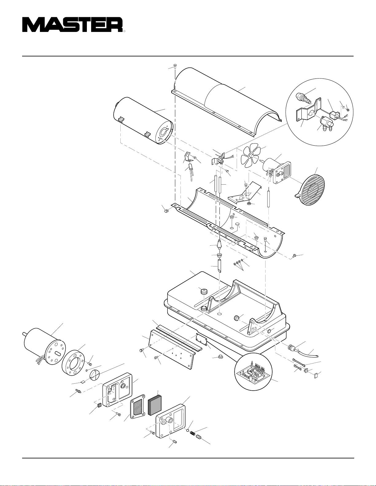
R
1
2
3
23
19
9
10
16
11
12
15
25
27
24
28
20
22
21
30
31
17
14
14
35
36
32
26
13
18
5
4
6
7
8
7-2
7-1
7-5
7-4
7-3
7-6
43
42
41
33
34
37
40
39
44
38
29
APPAREILS DE CHAUFFAGE INDIVIDUELS À AIR FORCÉ
VUE ÉCLATÉE
MODÈLE B150CEH
10-1
10-4
10-5
10-2
10-3
10-17
10-16
10-15
10-18
Ensemble moteur et pompe
10-14
10-6
10-13
10-7
10-12
10-8
10-9
10-10
10-11
22
105398
Page 51

MANUEL D’UTILISATION
LISTE DES PIÈCES
MODÈLE B150CEH
N˚ DE NUMÉRO
RÉF DU PIÈCE DESIGNATION QTÉ
1 098511-257 Couverture, haut 1
2 102432-01 Vis/rondelle frein,1/2" 8
3 098512-66 Chambre de Combustion 1
4 103154-05 Support de cellule
photoélectrique 1
5 M10908-2 Vis, #6-32 x 3/8" 2
6 M16656-24 Ensemble, cellule 1
7 ** Support d’ensemble de brûleur 1
7-1 100735-24 Gicleur 1
7-2 102548-05 Kit d’allumeur 1
7-3 M10908-75 Vis, #6-32 x 7/8" 1
7-4 102336-01 Support d’adaptateur
de gicleur 1
7-5 104054-01 Adaptateur de gicleur 1
7-6 103347-01 Rondelle Belleville 1
8 102431-01 Vis/rondelle frein,1/2" 2
9 102042-01 Ventilateur 1
10 ** Ensemble moteur et pompe 1
10-1 102001-24 Moteur 1
10-2 079975-03 Corps pompe 1
10-3 FHPF3-6C Vis, #10-32 x 3/4" 2
10-4 M22009 Pièce rapportée1
10-5 M22456-2 Rotor 1
10-6 M50545 Pompe, couverture extrémité 1
10-7 M12179 Filtre entrée1
10-8 M16545 Couverture filtre 1
10-9 M8940 Bille acier 1/4 diameter 1
10-10 M10993-1 Ressort de relâchement 1
10-11 M27694 Vis, d’ajustage 1
10-12 M22997 Prise 1
10-13 M12461-31 Vis, #10-32 x 1" 4
10-14 M12244-1 Filtre sortie 1
10-15 M11637 Toile filtre 1
10-16 M50820-02 MRaccord à griffes 1
10-17 M8643-2 Pale 4
10-18 M12461-32 Vis, #10-32 x 1
11 M50631 Amortisseur, caoutchouc 2
12 101206-01 Support, moteur 1
13 101695-01 Bouchon rond 1
14 104068-04 Commande d’allumage 1
15 NTC-4C Ecrou, Hex 2
Cette liste comprend les pièces de l’appareil de chauffage qui peuvent être remplacées. Lors
de la commande de pièces détachées, veiller à inclure le numéro de modèle et les numéros
de série corrects (pris sur la plaque signalétique), puis le numéro de pièce et la désignation
de la pièce désirée.
N˚ DE NUMÉRO
RÉF DU PIÈCE DESIGNATION QTÉ
16 M51114-01 Garde de ventilateur 1
17 M27417 Bouchon de vidange
18 099213-01 Bouchon rond 1
19 M51345-04 Ligne d’alimentation
20 107961-01 Filtre, ensemble 1
21 M51151-02 Conduite de carburant 1
22 M10990-3 Bague, caoutchouc 1
23 M50814-03 Ligne d’air 1
24 098511-236 Couverture inférieure 1
25 M50104-03 Bague 1
26 M50104-01 Bague 1
27 102431-01 Vis/rondelle frein,1/2" 6
28 M11271-8 Ecrou, serrage 8
29 RF3-4B Vis, #10-32 x 1/2" 1
30 108088-05 Réservoir combustible 1
31 097702-01 Bouchon, réservoir
32 102349-01 Support de carte PC 5
33 M50400
34 079673-07 Câble de puissance 1
35 M51077-15 Couverture latérale 1
36 102431-01 Vis/rondelle frein,1/2" 4
37 102861-01 Écrou de blocage en Nylon 1
38 079010-39 Ensemble fil (marron) 1
39 105793-01 Interrupteur MARCHE/ARRÊT1
40 079919-01 Couvercle d’interrupteur 1
41 WLE-3 Rondelle, #10 1
42 NPF-3B Ecrou, #10-32 3
43 097468-01 Garniture de bordure 1
44 079010-40 Ensemble fil (blanc) 1
1
/8"6
(comprend un joint torique) 1
combustible 1
combustible 1
Bague, relâchement de tension
PIÈCES DISPONIBLES - NON ILLUSTRÉES
HA2210 Ecran, cou remplissage 1
103814-01 Serre-fils 1
097650-01 Decal, Nom de marque 2
106013-04 Jeu d'autocollants 1
105880-01 Fusible 1
1
** N’est pas disponible monté, commander les pièces séparément.
105398
23
Page 52
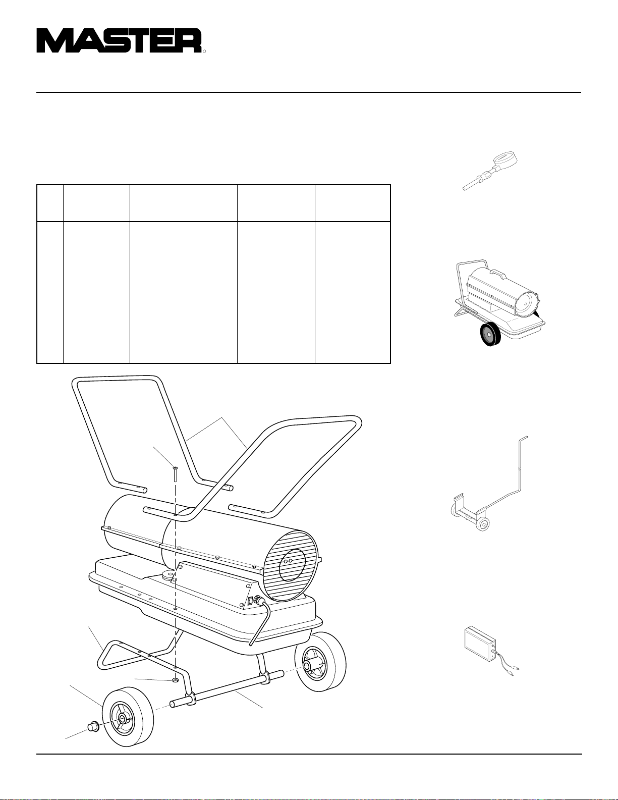
R
APPAREILS DE CHAUFFAGE INDIVIDUELS À AIR FORCÉ
ROUES ET
GUIDONS
MODÈLES B100CEH ET
B150CEH
NUMÉRO QTÉ QTÉ
RÉF DE PIÈCE DÉSIGNATION B100CEH B150CEH
1 HA2203 Guidon 2 —
HA2204 Guidon — 2
2 M12345-33 Vis n˚10-24 x 1 3/4 in 88
3 M12342-3 Berceau 1 —
M12831-3 Berceau — 1
4 NTC-3C Écrou
autobloquant n˚10-24 8 8
5 107426-01 Roue (2) 11
6 M28526 Écrou borgne 22
7 M51015-01 Essieu 1 —
M16801-2 Essieu — 1
1
ACCESSOIRES
Se procurer les accessoires auprès du concessionnaire local.
JEU DE MANOMÈTRE
HA1180
Pour tous les modèles. Outil conçu pour
vérifier la pression de la pompe.
JEU DE ROUES ET POIGNÉE
POUR USAGE INTENSIF
HA1202
Rend votre appareil de chauffage encore
plus pratique et facile à porter. Pour Modèles B35CEH et B70CEH.
2
JEU DE ROUES ET
POIGNÉES STANDARD
HA1206
Rend votre appareil de chauffage encore plus
pratique et facile à porter. Facile à monter.
Pour Modèles B35CEH et B70CEH.
3
5
4
TESTEUR DE COMMANDE
A 008
D’ALLUMAGE/CELLULE
7
6
PHOTOÉLECTRIQUE - HA1170
Outil spécial utilisé pour tester la commande
d’allumage et la cellule photoélectrique.
24
105398
Page 53

DÉCLARATION DE
CONFORMITÉ À LA CE
DÉCLARATION DE CONFORMITÉ À LA CE
Bowling Green, KY 42101 U.S.A.
Appareils de chauffage individuels à air forcé au kérosène
Numéro de modèle : B35CEH, B70CEH, B100CEH, B150CEH
MANUEL D’UTILISATION
DESA Europe B.V.
Innsbruckweg 144, 3047 AH
Postbus 11158
3004 ED Rotterdam
Hollande
Fabricant :
DESA International, Inc.
2701 Industrial Drive
Ces modèles ont été déclarés conformes à la directive machinerie 98/37/CE, y
compris 91/368/CEE et la directive basse tension 73/23/CEE. Ces modèles sont en
outre conformes à la directive de CEM 89/336/CEE, amendée par la 92/31/CEE, y
compris EN50081-1 et EN50082-1.
Nous déclarons que les modèles mentionnés sont en conformité.
Compagnie DESA International, Inc.
Nom Joseph B. Lee
Titre Vice-président, Ingéniérie des produits de chauffage
07/25/2000 — Bowling Green, KY
Date et lieu Signature
105398
25
Page 54

GARANTIE ET RÉPARATIONS
CERTIFICAT RELATIF AU MATÉRIEL GÉNÉRAL -
GARANTIE LIMITÉE D’UN AN
Les produits neufs vendus par la société DESA International sont garantis pièces et main-d’oeuvre contre les vices de
matériaux et de fabrication, pour une période d’un an à compter
de la date de livraison, et ce, au premier utilisateur et sous
réserve des conditions suivantes :
Les obligations et la responsabilité de la société DESA
International en vertu de la présente garantie se limitent
expressément à la réparation ou au remplacement, à la
discrétion de la société, de toute pièce qui lui semblerait, après
inspection, défectueuse au moment de l’expédition de l’usine en
raison d’un vice de matériau et de fabrication. La ou lesdites
pièces seront remplacées gratuitement et mises à la disposition
de l’utilisateur dans les locaux de tout centre d’entretien dûment
autorisé par l’usine de fabrication, ou à l’usine même, et ce
durant les heures normales d’ouverture. La présente garantie
ne couvre pas les pièces et accessoires non fabriqués par
DESA International et couverts par la garantie de leur propre
fabricant ; elle ne couvre pas non plus l’entretien habituel (par
exemple, les réglages de la pression) ni les pièces d’entretien
habituelles (telles que les filtres et les bougies). Les pièces de
remplacement ou de réparation posées sur le produit couvert
par la présente garantie ne seront elles-mêmes couvertes que
pour la durée restante de la garantie, tout comme si elles avaient
été des pièces d’origine dudit produit. AUCUNE AUTRE
GARANTIE EXPRESSE N’EST ÉMISE PAR LA SOCIÉTÉ
DESA INTERNATIONAL. DANS LES LIMITES PRESCRITES
PAR LA LOI, DESA INTERNATIONAL N’ÉMET AUCUNE
GARANTIE IMPLICITE, NI AUCUNE GARANTIE DE QUALITÉ
LOYALE ET MARCHANDE OU DE CONFORMITÉ À
L’UTILISATION PRÉVUE. QUOI QU’IL EN SOIT, LES
GARANTIES IMPLICITES, Y COMPRIS LES GARANTIES DE
QUALITÉ LOYALE ET MARCHANDE OU DE CONFORMITÉ
À L’UTILISATION PRÉVUE, SONT LIMITÉES À LA DURÉE
DE LA PRÉSENTE GARANTIE EXPRESSE.
Tous les frais de transport et d’installation, les droits, les
impôts ou tout autre frais de quelque nature que ce soit seront
à la charge de l’utilisateur. La société DESA International ne
saurait être responsable, en vertu de la présente garantie
limitée, de quelque dommage direct, indirect ou accessoire
que ce soit, ou de retards. Les produits ou pièces faisant l’objet
d’une demande en vertu de la présente garantie devront être
renvoyés à l’usine par l’utilisateur en port payé, à la demande
de la société DESA International. La présente garantie sera
réputée nulle et de nul effet en cas d’usage abusif, y compris
en cas d’utilisation après la découverte des pièces
défectueuses ou usées, d’utilisation au-delà des capacités du
produit, de substitution de pièces non approuvées par DESA
International, ou encore en cas de modification ou de
réparation, de quelque nature que ce soit, effectuée par un tiers
d’une façon telle que, selon DESA International, le produit en
est affecté matériellement et défavorablement.
LES EMPLOYÉS OU MANDATAIRES NE SONT EN
AUCUN CAS AUTORISÉS À MODIFIER EN QUOI QUE CE
SOIT LA PRÉSENTE GARANTIE, NI À ACCORDER UNE
AUTRE GARANTIE DE QUELQUE NATURE QUE CE SOIT,
SANS L’AUTORISATION PRÉALABLE ÉCRITE ET SIGNÉE
PAR UN MEMBRE DU BUREAU DE LA SOCIÉTÉ DESA
INTERNATIONAL, À SON SIÈGE SOCIAL.
Printed in U.S.A.
SERVICES FOURNIS AU TITRE DE LA GARANTIE
Toujours indiquer le modèle et les numéros de série dans la
correspondance avec l’usine.
Nous nous réservons le droit de modifier à tout moment les
présentes spécifications sans préavis. La seule garantie applicable est notre garantie écrite standard. Aucune autre garantie,
expresse ou implicite, n’est faite.
Un manuel d’entretien peut être obtenu auprès du Service
d’entretien technique à l’adresse suivante :
INTERNATIONAL
Corporate Headquarters
2701 Industrial Drive
P.O. Box 90004
Bowling Green, KY 42102-9004
U.S.A.
Page 55

R
VERPLAATSBARE
HETELUCHT-
KANONNEN
GEBRUIKERSHANDLEIDING
Vermogen: 35.000, 70.000, 100.000 en 150.000 Btu/uur
Modellen: B35CEH, B70CEH, B100CEH, en B150CEH
BELANGRIJK: Lees deze handleiding en zorg dat u hem begrijpt alvorens het
heteluchtkanon in elkaar te zetten, aan te zetten of er onderhoud aan uit te voeren. Verkeerd gebruik van dit heteluchtkanon kan tot ernstig letsel leiden. Bewaar
deze handleiding voor toekomstig gebruik.
Page 56

R
VERPLAATSBARE HETELUCHTKANONNEN
VEILIGHEIDSINFORMATIE
WAARSCHUWING
BELANGRIJK: Lees deze
gebruikershandleiding aandachtig en volledig door alvorens het
heteluchtkanon in elkaar te zetten, aan te zetten of er onderhoud
aan uit te voeren. Verkeerd gebruik van dit heteluchtkanon kan
leiden tot letsel of de dood als
gevolg van brandwonden, brand,
ontploffing, elektrische schok of
koolmonoxydevergiftiging.
GEVAAR: Koolmonoxydevergiftiging kan de dood tot gevolg hebben!
Koolmonoxydevergiftiging: Aanvankelijke
symptomen van koolmonoxydevergiftiging
lijken op griep met hoofdpijn, duizeligheid
en/of misselijkheid. Als u deze symptomen
vertoont, kan het zijn dat het heteluchtkanon
niet naar behoren werkt. Zorg dat u onmid-
dellijk frisse lucht krijgt! Laat de kachel
nakijken. Sommige mensen hebben meer
last van koolmonoxydevergiftiging dan anderen. Hieronder vallen zwangere vrouwen,
mensen met hart- of longziekten of bloedarmoede, mensen onder de invloed van alcohol
en mensen die zich op grote hoogte boven
zeeniveau bevinden.
Zorg dat u alle waarschuwingen leest en
begrijpt. Bewaar deze handleiding voor toekomstig gebruik. Deze handleiding biedt
uitkomst voor het veilige en juiste gebruik
van deze kachel.
• Gebruik uitsluitend lichtpetroleum of
huisbrandolie nr. 1 (hbo 1) om brand- en
explosiegevaar te beperken. Gebruik nooit
benzine, nafta, verfverdunner, alcohol of
andere brandgevaarlijke brandstoffen.
• Bijvullen
a) Het personeel dat brandstof toedient
dient bevoegd te zijn en goed bekend
met de aanwijzingen van de fabrikant
en de toepasselijke voorschriften voor
het bijvullen van heteluchtkanonnen.
b) Uitsluitend het soort brandstof opge-
geven op het gegevensplaatje van het
heteluchtkanon mag worden gebruikt.
c) Voor het bijvullen moeten alle vlam-
men, met inbegrip van het waakvlammetje, worden gedoofd en moet
het heteluchtkanon afkoelen.
d) Tijdens het bijvullen moeten alle
brandstofleidingen en -aansluitingen
op lekken worden gecontroleerd.
Lekken moeten worden gerepareerd
alvorens het heteluchtkanon weer in
gebruik te nemen.
e) Nooit mag een voorraad
verwarmingsbrandstof voor meer dan
één dag in een gebouw in de nabijheid van het heteluchtkanon worden
opgeslagen. Grote hoeveelheden
brandstof dienen buiten het gebouw
te worden opgeslagen.
f) Alle brandstof dient ten minste 7,62
m (25 voet) van heteluchtkanonnen,
blaaslampen, lasapparatuur en soortgelijke ontstekingsbronnen te worden
opgeslagen (behalve de brandstoftank
van het heteluchtkanon).
g) Zo mogelijk dient brandstof te wor-
den opgeslagen op plaatsen waar geen
mogelijkheid bestaat dat de brandstof
door de vloer op een lager gelegen
vuur druppelt of daardoor wordt ontstoken.
h) De brandstof moet worden opgesla-
gen conform de voorschriften van de
competente landelijke of plaatselijke
overheid.
• Gebruik het heteluchtkanon nooit in de
buurt van benzine, verfverdunner of
brandgevaarlijke dampen.
• Volg alle wettelijke voorschriften bij gebruik van dit heteluchtkanon.
• Heteluchtkanonnen die worden gebruikt
in de nabijheid van dekkleden, canvas of
soortgelijk bedekkingsmateriaal dienen
zich op veilige afstand van deze stoffen
te bevinden. De aanbevolen minimumafstand is 3,05 m (10 voet). Het wordt
verder aanbevolen brandvertragend
bedekkingsmateriaal te gebruiken. Dit
bedekkingsmateriaal moet stevig worden
vastgemaakt om te voorkomen dat het bij
een windstoot ontbrandt of het heteluchtkanon doet omvallen.
• Alleen in goed geventileerde ruimten
gebruiken. Zorg voor ten minste één opening van 2800 cm2 voor iedere 100.000
Btu/uur vermogen voor de toevoer van
frisse buitenlucht.
• Gebruik het heteluchtkanon niet in ruimten met hoge concentraties van brandbare
dampen of stof.
• Sluit het heteluchtkanon uitsluitend aan
op de netspanning die op het modelplaatje is aangegeven.
• Gebruik uitsluitend een geaard verlengsnoer.
• Minimum afstand tussen het heteluchtkanon en brandbaar materiaal:
uitlaatopening 2,5 m; zij-, boven- en achterkant: 1,25 m.
• Plaats het heteluchtkanon op een stevige
en vlakke ondergrond zolang dit heet of
in werking is; anders kan er brand ontstaan.
• Houd het heteluchtkanon recht tijdens het
verplaatsen of opbergen; anders zal er
brandstoflekkage optreden.
• Houd kinderen en dieren uit de buurt van
het heteluchtkanon.
• Neem de stekker uit het stopcontact wanneer het heteluchtkanon niet in gebruik is.
• Bij gebruik van de thermostaat kan het
heteluchtkanon te allen tijden automatisch aanslaan.
• Gebruik het heteluchtkanon nooit in
woon- of slaapvertrekken.
• Blokkeer nooit de toevoeropening (achterkant) of de uitlaatopening (voorkant)
van het heteluchtkanon.
• Een werkende, hete of op het lichtnet
aangesloten kachel mag niet verplaatst,
gehanteerd of bijgevuld worden en er
mag geen onderhoud aan uitgevoerd
worden.
• Bevestig nooit een buizensysteem aan de
voor- of achterkant van het heteluchtkanon.
2
105398
Page 57

GEBRUIKERSHANDLEIDING
PRODUKTIDENTIFIKATIE
Heteluchtuitlaat
Bovenste deel
van behuizing
Onderste deel
van behuizing
Brandstoftank
Zijpaneel
AN/UIT-schakelaar
met lampje
Figuur 1 - Modellen B35CEH en B70CEH
Heteluchtuitlaat
Onderste
deel van
behuizing
Dop brandstoftank
Handvat
Luchtfilterdeksel
Netsnoer
Bovenste deel van behuizing
Ventilatorrooster
Dop brandstoftank
Ventilatorrooster
Brandstoftank
UITPAKKEN
1. Verwijder al het verpakkingsmateriaal
dat voor verzending gebruikt is.
2. Haal alle onderdelen uit de doos.
3. Controleer alle onderdelen op even-
tuele schade, opgelopen tijdens verzending. Als het heteluchtkanon beschadigd is, dient u onmiddellijk de leverancier bij wie u het gekocht hebt, op
de hoogte te brengen.
BRANDSTOFFEN
WAARSCHUWING: Gebruik
uitsluitend lichtpetroleum of huisbrandolie nr. 1 (hbo 1) om branden explosiegevaar te beperken.
Gebruik nooit benzine, nafta, verfverdunner, alcohol of andere
brandgevaarlijke brandstoffen.
Huisbrandolie nr. 2 (hbo 2) of diesel nr. 2
mag niet gebruikt worden. Gebruik van deze
brandstoffen leidt tot:
• verstopping van brandstoffilter en sproeier
• noodzaak voor niet-giftig antivries in
brandstof bij zeer koud weer
BELANGRIJK:
UITSLUITEND VOOR LICHTPETROLEUM bestemd is. Zorg dat de container schoon is. Vuil in de brandstof, zoals
roest of water, stellen het
vlamdovingssysteem in werking waardoor
het heteluchtkanon afslaat. Daarnaast moet
als gevolg van vuil het brandstofsysteem
vaker worden schoongemaakt.
Gebruik een container die
Zijpaneel
Figuur 2 - Modellen B100CEH en B150CEH
105398
Netsnoer
AN/UIT-schakelaar
met lampje
3
Page 58

R
VERPLAATSBARE HETELUCHTKANONNEN
MONTAGE
(ALLEEN VOOR MODELLEN
B100CEH EN B150CEH)
Deze modellen zijn voorzien van een onderstel met wielen en hendels. De wielen, hendels en montage-onderdelen bevinden zich
in de doos.
Benodigd gereedschap
• Een middelgrote kruiskopschroevedraaier
• Een steeksleutel of Engelse sleutel (3/8")
• Een hamer
1. Schuif de as door het onderstel. Installeer de wielen op de as.
RIJK:
Zorg dat de wielen met de kant
met de uitstekende naaf naar het frame
toe worden aangebracht (zie figuur 3).
Heteluchtuitlaat
BELANG-
Schroef
2. Breng de asmoeren aan op de uiteinden
van de as. Klop voorzichtig met een hamer op de moeren om ze vast te zetten.
3. Leg het heteluchtkanon op het onderstel. Zorg dat de luchtinlaatopening
(achterkant) zich boven de wielen bevindt. Breng de gaten in de rand rond
de brandstoftank in lijn met de gaten
in het onderstel.
4. Plaats de voorste en achterste hendel
op de rand rond de tank. Steek de
schroeven door de hendels, de rand
rond de tank en het onderstel. Bevestig
na het aanbrengen van iedere schroef
een moer; draai deze met de hand vast.
5. Draai alle moeren stevig vast nadat alle
schroeven zijn aangebracht.
Voorste hendel
Achterste
hendel
VENTILATIE
WAARSCHUWING: Het voorschrift voor minimale toevoer van
frisse buitenlucht moet opgevolgd worden. Als voldoende
frisse buitenlucht niet voorhanden is, kan koolmonoxydevergiftiging optreden. Zorg voor
voldoende aanvoer van frisse
buitenlucht alvorens het heteluchtkanon aan te zetten.
Zorg voor een opening voor frisse lucht van
ten minste 2800 cm2 voor iedere 100.000
Btu/uur aan vermogen. Zorg voor meer toevoer van frisse lucht indien meerdere kachels worden gebruikt.
Voorbeeld:
Btu/uur vereist een van de volgende:
• een dubbele garagedeur [4,9 meter (16')
breed] die 9 cm (3,5") van de grond geopend is
• een enkele garagedeur [2,75 meter (9')
breed] die 15,25 cm (6") van de grond
geopend is
• twee ramen met een breedte van 76 cm
(30") geopend op 28 cm (11")
Een heteluchtkanon van 150.000
Rand rond
brandstoftank
Onderstel
Wiel
Asmoer
Figuur 3 - Hendels en onderstel met wielen
Moer
Uitstekende naaf
As
Luchtinlaat
4
105398
Page 59

GEBRUIKERSHANDLEIDING
OVERZICHT VAN
DE WERKING
Het brandstofsysteem: De luchtpomp
pompt lucht door de luchtslang. De lucht
wordt vervolgens door de sproeier van de
branderkop gestuurd. Deze lucht zuigt brandstof uit de tank aan. Een nevel van brandstof
wordt vervolgens in de verbrandingskamer
gespoten.
Het luchtsysteem: De motor drijft de
ventilator aan. De ventilator stuwt lucht in
en rond de verbrandingskamer. Deze lucht
wordt verwarmd en levert een schone, hete
luchtstroom.
Het ontstekingssysteem: Het ontstekings-
mechanisme stuurt spanning naar de
ontsteker. Hierdoor ontsteekt het mengsel
van brandstof en lucht in de verbrandingskamer.
Het vlamdovingssysteem: Dit systeem
dient om het heteluchtkanon uit te schakelen wanneer de vlam uitgaat.
BEDIENING
WAARSCHUWING: Lees de
waarschuwingen in het hoofdstuk
Veiligheids-informatie
maals door en zorg dat u ze begrijpt. Ze zijn nodig om deze kachel veilig te laten werken. Houd
u aan alle plaatselijke voorschriften wanneer u dit heteluchtkanon
gebruikt.
HET HETELUCHTKANON
AANZETTEN
1. Volg alle informatie over installatie,
ventilatie en veiligheid.
2. Vul de tank met lichtpetroleum of huisbrandolie nr. 1 (hbo 1).
3. Draai de dop op de tank.
4. Steek de stekker van de kachel in een
standaard, geaard stopcontact van 230~
V/50 Hz. Gebruik eventueel een
verlengsnoer. Gebruik uitsluitend geaarde stekkers met drie pennen.
nog-
VERLENGSNOEREN
Gebruik 1,0 mm2 (16 AWG) geleider voor
kabels met een lengte van minder dan 30,5 m.
Gebruik 1,5 mm
2
(14 AWG) geleider voor
kabels met een lengte van 30,5 m tot 61 m.
Duw de AAN/UIT-schakelaar naar de stand
AAN (|) en de kachel hoort binnen 5 seconden aan te slaan. Als de kachel niet aanslaat,
dient u Problemen oplossen (pagina 7 en 8)
te raadplegen.
HET HETELUCHTKANON
UITZETTEN
Duw de AAN/UIT-schakelaar naar UIT
(OFF).
DE KACHEL OPNIEUW
AANZETTEN
1. Duw de AAN/UIT-schakelaar naar de
stand UIT (0) en wacht 10 seconden (2
minuten als de verwarming al heeft aangestaan).
2. Herhaal de procedure op pagina 5 onder Het heteluchtkanon aanzetten.
Verbrandingskamer
Ontsteker
Schone
heteluchtstroom
Brandstoftank
Figuur 4 - Bedrijfsaanzicht, dwarsdoorsnede
Sproeier
Lucht voor
brandstofsysteem
Brandstoffilter
Motor
Ventilator
Luchtslang
naar
brander
Lucht voor verbranding en verwarming
Luchtpomp
Luchtinlaatfilter
Koele
lucht
naar
binnen
Elektronisch
ontstekingsmechanisme
Brandstof
Luchtuitlaatfilter
|
AN/UIT-schakelaar
met lampje
O
Figuur 5 - Reset-knop vlamdovingssysteem,
modellen B35CEH en B70CEH
AN/UIT-
|
schakelaar
O
met lampje
105398
Figuur 6 - Reset-knop vlamdovingssysteem,
modellen B100CEH en B150CEH
5
Page 60

R
VERPLAATSBARE HETELUCHTKANONNEN
OPSLAG, VERVOER
OF VERZENDING
Let op:
bedrijven dat de brandstoftanks leeg zijn.
1. Laat de brandstoftank leeglopen.
2. Breng de aftapstop weer aan, indien van
3. Als u deeltjes in de oude brandstof ziet,
4. Breng de brandstofdop of aftapstop
5. Berg het heteluchtkanon op een droge
BELANGRIJK:
dens de zomermaanden opgeslagen is geweest, nooit in het volgende stookseizoen.
Het gebruik van oude brandstof kan het
heteluchtkanon beschadigen.
Bij verzending vereisen transport-
Let op:
Sommige modellen hebben een
aftapstop aan de onderkant van de
brandstoftank. Als deze aanwezig is,
verwijder de aftapstop dan om alle
brandstof te laten weglopen. Als het
heteluchtkanon geen aftapstop heeft,
moet de brandstof via de opening voor
de brandstofdop verwijderd worden.
Zorg dat alle brandstof uit de tank verwijderd wordt.
toepassing.
giet dan 1 of 2 liter schone petroleum
in de tank. Roeren en weer aftappen.
Hierdoor wordt voorkomen dat overtollige deeltjes bij toekomstig gebruik
de filters verstoppen.
weer aan. Werp oude en vuile brandstof op verantwoorde wijze weg. Raadpleeg plaatselijke benzinestations die
olie recyclen.
plaats op. Controleer of op deze plaats
geen stof en roestvormende dampen
aanwezig zijn.
Gebruik petroleum die tij-
PREVENTIEF
ONDERHOUD
Onderdeel
Brandstoftank
Luchtuitlaat- en
lintfilter
Luchtinlaatfilter
Brandstoffilter
Ontsteker
Ventilatorschoepen
Motor
Wanneer?
Na iedere 150-200 bedrijfsuren of zonodig uitspoelen
Na 500 bedrijfsuren of eens
per jaar vervangen
Iedere 500 bedrijfsuren of
zonodig met water en zeep
wassen en laten drogen
Tweemaal per stookseizoen
of zonodig schoonmaken
Geen onderhoud vereist
Eenmaal per stookseizoen of
zo nodig schoonmaken
Niet vereist/permanente
smering
WAARSCHUWING: Voer nooit onderhoud uit aan de kachel als de stekker niet uit het stopcontact is verwijderd of als de kachel nog werkt of heet
is. Ernstige brandwonden of elektrische
schok kunnen het gevolg zijn.
Onderhoud
Zie Opslag, Vervoer of Verzending
Zie Het luchtuitlaat luchtinlaat- en
lintfilter, pagina 11
Zie Het luchtuitlaat-, luchtinlaat-
en lintfilter, pagina 11
Zie Brandstoffilter, pagina 9
Zie Ventilator, pagina 14
6
105398
Page 61

GEBRUIKERSHANDLEIDING
PROBLEMEN
OPLOSSEN
WAARSCHUWING: Voer nooit onderhoud uit aan de kachel als de
stekker niet uit het stopcontact is verwijderd of als de kachel nog werkt
of heet is. Ernstige brandwonden of elektrische schok kunnen het
gevolg zijn.
VERWARMER MET ONTSTEKINGSMECHANISME MET OF ZONDER ZEKERING
PROBLEEM
Motor slaat niet aan binnen vijf seconden
nadat de stekker in het stopcontact is gestoken
(Het lampje van de AAN/UIT-schakelaar
blijft branden)
Motor slaat aan en werkt maar kachel brandt
niet (Het lampje van de AAN/UIT-schakelaar blijft branden)
MOGELIJKE OORZAAK
1. Geen goede elektrische aansluiting tussen motor en ontstekingsmechanisme of
ontstekingsmechanisme en netsnoer
WAARSCHUWING: Hoogspanning!
2. Pomprotor loopt aan
3. Defect ontstekingsmechanisme
4. Defecte motor
1. Geen brandstof in tank
2. Verkeerde pompdruk
3. Vuile brandstoffilter
4. Vuil in sproeier
5. Water in brandstoftank
OPLOSSING
1. Alle elektrische aansluitingen controleren. Zie Bedradingsschema’s, pagina 15
2. Als de ventilator slechts met moeite
kan worden gedraaid, zie Pomprotor,
pagina 13
3. Ontstekingsmechanisme vervangen
4. Motor vervangen
1. Tank met lichtpetroleum vullen
2. Zie De pompdruk bijstellen, pagina 11
3. Zie Brandstoffilter, pagina 9
4. Zie Sproeier, pagina 12
5. Brandstoftank laten leeglopen en uitspoelen met schone lichtpetroleum. Zie
Opslag, vervoer of verzending, pagina 6
Kachel slaat aan maar ontstekingsmechanisme zet kachel na enige tijd uit
(Het lampje van de AAN/UIT-schakelaar
blijft branden)
WAARSCHUWING: Hoogspanning!
6. Geen goede elektrische aansluiting tussen ontsteker en ontstekingsmechanisme
7. Defecte ontsteker
8. Defect ontstekingsmechanisme
1. Verkeerde pompdruk
2. Vuile luchtinlaat-, luchtuitlaat- en/of
lintfilter
3. Vuile brandstoffilter
4. Vuil in sproeier
5. Fotocel niet goed aangebracht (ziet de
vlam niet)
WAARSCHUWING: Hoogspanning!
6. Vuile fotocellens
7. Geen goede elektrische verbinding tussen fotocel en ontstekingsmechanisme
8. Defecte fotocel
9. Defect ontstekingsmechanisme
6. Elektrische aansluitingen controleren
Zie Bedradingsschema’s, pagina 15
7. Ontsteker vervangen, zie pagina 10
8. Ontstekingsmechanisme vervangen
1. Zie De pompdruk bijstellen, pagina 11
2. Zie Het Luchtuitlaat-, luchtinlaat- en
lintfilter, pagina 11
3. Zie Brandstoffilter, pagina 9
4. Zie Sproeier, pagina 12
5. Controleren of het verbindingsstuk van
de fotocel goed in de beugel grijpt
6. Fotocellens schoonmaken
7. Elektrische aansluitingen controleren.
Zie Bedradingsschema’s, pagina 15
8. Fotocel vervangen
9. Ontstekingsmechanisme vervangen
105398
Wordt vervolgd
7
Page 62

R
VERPLAATSBARE HETELUCHTKANONNEN
PROBLEMEN
OPLOSSEN
Vervolg
VERWARMER MET ONTSTEKINGSMECHANISME ZONDER ZEKERING
ATTENTIE:
schakelaar om de storing op te sporen.
Het ontstekingsmechanisme heeft een ingebouwde bescherming tegen overbelasting. Gebruik het lampje van de AAN/UIT-
PROBLEEM
Het lampje van de AAN/UIT-schakelaar
gaat niet branden wanneer de schakelaar in
de AAN-stand (|) wordt gezet en de verwarming start niet
Het lampje van de AAN/UIT-schakelaar
gaat branden wanneer de schakelaar in de
AAN-stand (|) wordt gezet, maar het gaat
uit na vijf seconden
MOGELIJKE OORZAAK
1. Geen stroom naar verwarmer
WAARSCHUWING: Hoogspanning!
2. Slechte elektrische verbindingen
3. Kortsluiting in generator
1. Kortsluiting in de motor
WAARSCHUWING: Hoogspanning!
OPLOSSING
1. Kijk na of de stroomkabel op een stopcontact is aangesloten en of de stroomonderbreker in het elektriciteitspaneel is
teruggezet.
2. Controleer de elektrische bedrading en
verbindingen. Zie Bedradingsschema,
pagina 15
3. Controleer de bedrading van de ontsteker.
Als u geen problemen vindt, vervang dan
de ontsteker (zie pagina 10)
1. Controleer de bedrading van de motor.
Als u geen problemen vindt, vervang dan
de motor
8
105398
Page 63

GEBRUIKERSHANDLEIDING
ONDERHOUDSPROCEDURES
WAARSCHUWING: Voer nooit
onderhoud uit aan de kachel als
de stekker niet uit het stopcontact is verwijderd of als de kachel
nog werkt of heet is. Ernstige
brandwonden of elektrische
schok kunnen het gevolg zijn.
DE BEHUIZING VERWIJDEREN
1. Verwijder schroeven aan beide zijden
van kachel met een dopsleutel (5/16").
Met deze schroeven worden boven- en
onderkant van behuizing aan elkaar
bevestigd.
2. Til bovenste deel van de behuizing van
kachel af.
3. Verwijder ventilatorrooster.
BRANDSTOFFILTER
(Modellen B35CEH en B70CEH)
1. V erwijder schroeven van zijpaneel met
een dopsleutel (5/16").
2. Verwijder zijpaneel.
3. Trek rubber brandstofslang van aansluiting op brandstoffilter.
4. Verwijder filter en bus voorzichtig uit
brandstoftank.
5. Was filter met schone brandstof en
plaats hem weer terug.
6. Breng rubber slang weer aan op aansluiting van filter.
7. Plaats zijpaneel weer terug.
BRANDSTOFFILTER
(Modellen B100CEH en
B150CEH)
1. V erwijder schroeven van zijpaneel met
een dopsleutel (5/16").
2. Verwijder zijpaneel.
3. Trek bovenste brandstofslang van aansluiting op brandstoffilter.
4. Verwijder voorzichtig bus, onderste
brandstofslang en filter uit brandstoftank.
5. Was filter met schone brandstof en
plaats hem weer terug.
6. Breng bovenste slang weer aan op aansluiting van filter.
7. Plaats zijpaneel weer terug.
Bovenste deel
van behuizing
Figuur 7 - Verwijderen van bovenste deel
van behuizing, modellen B35CEH en
B70CEH
Brandstoffilter
Zijpaneel
Figuur 9 - Verwijderen van brandstoffilter, modellen B35CEH en B70CEH
Brandstoffilter,
bus en onderste
brandstofslang
Zijpaneel
Figuur 10 - Verwijderen van brandstoffilter, modellen B100CEH en B150CEH
Ventilatorrooster
Figuur 8 - Verwijderen van bovenste deel
van behuizing, Modellen B100CEH en
B150CEH
Brandstofslang
Bovenste deel
van behuizing
Ventilatorrooster
Bovenste
brandstofslang
Wordt vervolgd
105398
9
Page 64

R
VERPLAATSBARE HETELUCHTKANONNEN
ONDERHOUDSPROCEDURES
Vervolg
ONTSTEKER
1. V erwijder bovenste deel van behuizing
en ventilatorrooster (zie pagina 9).
2. Verwijder ventilator (zie pagina 14).
3. V erwijder 4 schroeven uit zijpaneel met
moersleutel (5/16"). Verwijder zijpaneel (zie figuur 9 of 10, pagina 9).
4. Maak ontstekerkabels (zwart) los van
ontstekingsmechanisme (zie figuur 11).
Trek ontstekerkabels omhoog door
opening in onderste deel van behuizing.
5. Maak brandstof- en luchtslang los. Haal
fotocel van beugel (zie figuur 11).
Sproeieradapterbeugel
Verbrandingskamer
Brandstofslang
Ontsteker
6. Verwijder verbrandingskamer. Zet
verbrandingskamer rechtop met
sproeieradapterbeugel bovenop (zie figuur 12).
7. V erwijder schroef uit ontsteker met een
moersleutel (1/4"). Haal ontsteker voorzichtig uit sproeieradapterbeugel.
OPGELET: Ontstekerelement
niet buigen of erop slaan. Voorzichtig behandelen.
8. Haal nieuwe ontsteker voorzichtig uit
tempex verpakking.
9. Plaats ontsteker voorzichtig in opening
in sproeieradapterbeugel. Niet op het
ontstekerelement slaan. Bevestig
ontsteker met een schroef aan
sproeieradapterbeugel met behulp van
een moersleutel (1/4") (zie figuur 12).
Aandraaien tot 0,90 à 1,69 N-m (8 à 15
in-lb). Niet te strak aandraaien.
Schroef/sluitring van
ontsteker
10. Plaats verbrandingskamer terug.
11. Steek ontstekerkabels weer omlaag
door opening in onderste deel van behuizing. Sluit kabels aan op
ontstekingsmechanisme.
12. Plaats zijpaneel terug (zie figuur 9 of
10, pagina 9).
13. Sluit brandstof- en luchtslang aan op
branderkop. Zie Vervangen en juiste
plaatsing van brandstof- en luchtslang,
pagina 12.
14. Zet fotocel weer in fotocelbeugel. Leid
de kabels zoals afgebeeld in figuur 17,
18 of 19, pagina 12.
15. Plaats ventilator terug (zie pagina 14).
16. Plaats ventilatorrooster en bovenste
deel van behuizing terug (zie pagina 9).
Luchtslang
Ontstekerkabels
Fotocelbeugel
Fotocel
Zijpaneel
Figuur 11 - Ontstekerkabels losmaken
van ontstekingsmechanisme
Ontstekingsmechanisme
Ontstekerelement
Fotocelbeugel
Opening in
sproeieradapterbeugel
Sproeieradapterbeugel
Verbrandingskamerr
Figuur 12 - Vervangen van ontsteker
Ontsteker
10
105398
Page 65

GEBRUIKERSHANDLEIDING
ONDERHOUDSPROCEDURES
Vervolg
HET LUCHTUITLAAT-,
LUCHTINLAAT- EN LINTFILTER
1. V erwijder bovenste deel van behuizing
(zie pagina 9).
2. Verwijder schroeven uit filterdeksel
met een dopsleutel (5/16").
3. Verwijder filterdeksel.
4. Vervang luchtuitlaat- en lintfilter.
5. Was of vervang luchtinlaatfilter (zie
Preventief onderhoud, pagina 6).
6. Breng filterdeksel weer aan.
7. Breng ventilatorrooster en bovenste
deel van behuizing weer aan.
BELANGRIJK:
filters
DE POMPDRUK BIJSTELLEN
1. Verwijder manometerplug uit filterdeksel.
2. Monteer manometer (onderdeelnr.
HA1180).
3. Zet kachel aan (zie Bediening, pagina 5).
Laat motor op volle snelheid komen.
4. Stel druk bij. Draai overdrukklep naar
rechts voor hogere druk en naar links
voor lagere druk. Zie gegevens hiernaast
voor juiste druk voor diverse modellen.
5. Verwijder manometer. Breng
manometerplug weer in filterdeksel aan.
Breng geen olie aan op de
Luchtinlaatfilter
Filterdeksel
Lintfilter
Luchtuitlaatfilter
Figuur 13 - Luchtuitlaat-, luchtinlaat- en lintfilter, modellen B35CEH en B70CEH
Luchtinlaatfilter
Filterdeksel
Lintfilter
Luchtuitlaatfilter
Figuur 14 - Luchtuitlaat-, luchtinlaat- en lintfilter, modellen B100CEH en B150CEH
Manometerplug
Model Pompdruk
B35CEH 0,200 bar
B70CEH 0,338 bar
B100CEH 0,338 bar
B150CEH 0,380 bar
Ventilatorrooster
Ventilatorrooster
105398
Plastic kap
Figuur 15 - Verwijderen van
manometerplug
(Modellen B35CEH en B70CEH afgebeeld)
11
Overdrukklep
Manometer
Figuur 16 - De pompdruk bijstellen
Wordt vervolgd
Page 66

R
VERPLAATSBARE HETELUCHTKANONNEN
ONDERHOUDSPROCEDURES
Vervolg
SPROEIER
1. V erwijder bovenste deel van behuizing
(zie pagina 9).
2. Verwijder ventilator (zie pagina 14).
3. Maak brandstof- en luchtslang los van
sproeier (zie figuur 17, 18 of 19).
4. Draai sproeier kwartslag naar links en
trek hem naar motor toe om hem te
verwijderen (zie figuur 20).
5. Zet plastic zeskantig gedeelte losjes in
een bankschroef vast.
6. Verwijder sproeier voorzichtig uit
sproeieradapter met een dopsleutel (5/8").
Zie figuur 21.
7. Blaas perslucht door voorkant van
sproeier. Hierdoor komt eventueel vuil
uit sproeier los.
8. Controleer sproeierafdichting op beschadiging.
9. Draai sproeier weer in sproeieradapter tot
deze op zijn plaats zit. Nog 1/3 slag aandraaien met een dopsleutel (5/8") tot 4,5
à 5,1 N-m (40 à 45 in-lbs). Zie figuur 21.
10. Bevestig sproeier op branderbeugel.
11. Bevestig brandstof- en luchtslang aan
sproeier. Zie V ervangen en juiste plaatsing van brandstof- en luchtslang.
12. Plaats ventilator terug (zie pagina 14).
13. Plaats ventilatorrooster en bovenste
deel van behuizing terug (zie pagina 9).
Verbrandingskamer
Sproeieradapterbeugel
Fotocelbeugel
Sproeier/
Adapter
Luchtslang
Brandstofslang
Figuur 17 - Lucht- en brandslang verwijderen (uitsluitend Modellen B35CEH en
B70CEH)
Verbrandingskamer
Sproeieradapterbeugel
Luchtslang
Sproeier/
Adapter
Brandstofslang
Fotocelbeugel
Figuur 18 - VLucht- en brandslang verwijderen (Uitsluitend model B100CEH)
Verbrandingskamer
Sproeieradapterbeugel
Fotocelbeugel
Luchtslang
Brandstofslang
Figuur 19 - VLucht- en brandslang verwijderen (Uitsluitend model B150CEH)
Verbrandingskamer
Figuur 20 - Sproeier/adapter verwijeren
Voorkant sproeier
Sproeierafdichting
Sproeier
Sproeieradapter
Luchtslangnippel
Brandstofslangnippel
Figuur 21 - Sproeier en sproeieradapter
Sproeier/
Adapter
Sproeier/
Adapter
VERVANGEN EN JUISTE
PLAATSING VAN BRANDSTOF- EN LUCHTSLANG
1. V erwijder bovenste deel van behuizing
(zie pagina 9).
2. Maak schroeven uit zijpaneel los met
moersleutel (5/16").
3. Verwijder zijpaneel.
4.
Controleer brandstof- en luchtslang op
scheuren en/of gaten. Als brandstofslang
beschadigd is, losmaken van
sproeieradapter (zie figuur 17, 18 of 19) en
van brandstoffilter (zie pagina 9). Als luchtslang beschadigd is, losmaken van
sproeieradapter (zie figuur 17, 18 of 19) en
van koppelstuk op pompkap (zie figuur 22).
5. Breng nieuwe lucht- en/of brandstofslang aan. Bevestig het ene uiteinde van
luchtslang aan koppelstuk op pompkap
(zie figuur 22) en het andere uiteinde aan
sproeieradapter (zie figuur 17, 18 of 19).
Bevestig het ene uiteinde van brandstofslang aan brandstoffilter (zie pagina 9)
en het andere uiteinde aan
sproeieradapter (zie figuur 17, 18 of 19).
Bij kachels van Modellen B35CEH en
B70CEH lopen de lucht- en brandstofslang ongeveer zoals afgebeeld in figuur 17.
celbeugel niet aanraken.
Bij kachels van model B100CEH lopen de lucht- en brandstofslang ongeveer zoals afgebeeld in figuur 18.
op:
aanraken.
Bij kachels van model B150CEH lo-
pen de lucht- en brandstofslang ongeveer zoals afgebeeld in figuur 19.
op:
aanraken.
6. Plaats zijpaneel terug.
7. Plaats bovenste deel van behuizing en
ventilatorrooster terug (zie pagina 9).
Luchtslang
Figuur 22 - Luchtslang aan koppelstuk
Let op:
Slangen mogen foto-
Let
Slangen mogen fotocelbeugel niet
Let
Slangen mogen fotocelbeugel niet
Pompkap
Koppelstuk
12
105398
Page 67

GEBRUIKERSHANDLEIDING
ONDERHOUDSPROCEDURES
Vervolg
POMPROTOR
(Procedure voor klemmende
pomprotor)
1. V erwijder bovenste deel van behuizing
(zie pagina 9).
2. Draai schroeven van filterdeksel los
met een dopsleutel (5/16").
3. Verwijder filterdeksel en luchtfilters.
4. Draai schroeven van pompplaat los met
een dopsleutel (5/16").
5. Verwijder pompplaat.
6. V erwijder rotor , inzetstuk en schoepen.
7. Controleer of er vuil in pomp is. Eventueel schoonblazen met perslucht.
8. Breng inzetstuk en rotor weer aan.
9. Controleer speling rond rotor. Stel
eventueel bij op 0,076-0,101 mm (zie
figuur 25).
Let op:
voor te zorgen dat daar waar rotor dichtst bij
behuizing komt, de speling 0,076-0,101 mm
is. Zonodig bijstellen.
10. Plaats schoepen, pompplaat, luchtfilters
11. Breng ventilatorrooster en bovenste
12. Stel pompdruk bij (zie pagina 11).
Let op:
nog steeds klemt.
13. Volg stap 1 t/m 6 hierboven.
14. Leg vel fijn schuurpapier (nr. 600) op
15. Breng inzetstuk en rotor weer aan.
16. V oer bovenstaande stappen 10 t/m 12 uit.
Draai rotor één volledige slag om er
en filterdeksel weer terug.
deel van behuizing weer aan.
Volg onderstaande stappen als rotor
vlakke ondergrond. Schuur rotor lichtjes vier keer in een 8-baan patroon (zie
figuur 26).
Schoep
Pompplaat
Inzetstuk
Rotor
Luchtuitlaatfilter
Figuur 23 - Plaats van rotor, modellen B35CEH en B70CEH
Schoep
Inzetstuk
Rotor
Luchtuitlaatfilter
Figuur 24 - Plaats van rotor, modellen B100CEH en B150CEH
Stelschroef speling
Schoep
Luchtinlaatfilter
Filterdeksel
Pompplaat
Luchtinlaatfilter
Speling (0,076-0,101 mm)
gemeten met een voelermaat
Schuurpapier
Ventilatorrooster
Filterdeksel
Ventilatorrooster
105398
Rotor
Stelschroef speling
Figuur 25 - Plaats van stelschroeven
speling
13
Figuur 26 - Schuren van de rotor
Wordt vervolgd
Page 68

R
VERPLAATSBARE HETELUCHTKANONNEN
ONDERHOUDSPROCEDURES
Vervolg
VENTILATOR
BELANGRIJK:
ras alvorens motor uit kachel te nemen. Als
gewicht van motor op ventilator komt te rusten,
kan spoed van ventilator veranderd worden.
1. V erwijder bovenste deel van behuizing
(zie pagina 9).
2. Gebruik een inbussleutel (1/8") voor
losdraaien van stelschroef waarmee
ventilator op motoras zit.
3. Schuif ventilator van motoras af.
4. Maak ventilator schoon met een met
lichtpetroleum of oplosmiddel vochtig
gemaakte, zachte doek.
5. Droog ventilator grondig.
6. Plaats ventilator weer op motoras. Zorg
dat uiteinde van motoras gelijk ligt met
naaf van ventilator (zie figuur 28).
7. Plaats stelschroef op platte gedeelte van
as en draai hem stevig aan (4,5-5,6 N.m).
8. Breng ventilatorrooster en bovenste
deel van behuizing weer aan.
Stelschroef
Verwijder ventilator van moto-
Ventilator
ONTSTEKINGSMECHANISME
WAARSCHUWING: Haal de
stekker van het heteluchtkanon uit
het stopcontact voordat u service
uitvoert.
Oud ontstekingsmechanisme
verwijderen
1. V erwijder de vier schroeven uit het zijpaneel met een 5/16" moer- of dopsleutel (zie Figuur 29).
2. Maak de negen draden los van het
ontstekingsmechanisme.
3.
Grijp met behulp van een langbektang de
tab van de printplaatsteun en til deze op de
rand van het ontstekingsmechanisme (zie
Figuur 30). Herhaal dit voor de overige
vier printplaatsteunen en verwijder het mechanisme.
Zijpaneel
Figuur 29 – Deksel verwijderen
Zijpaneel
Nieum mechanisme installeren
OPGELET: Het
ontstekingsmechanisme bevat
elektrostatische componenten.
Houd het mechanisme vast aan
de randen van de printplaat. Raak
geen van de snelaansluitingen of
elektronische componenten aan.
1. Lijn de vijf gaten in het mechanisme
uit met de vijf printplaatsteunen in het
zijpaneel.
2. Houd het mechanisme vast aan de randen van de printplaat en oefen neerwaartse druk uit tot alle vijf de tabs van
de printplaatsteunen door veerkracht
worden vastgezet. Trek het mechanisme even omhoog om dit te controleren (zie Figuur 31).
3. Sluit de negen draden aan op het
ontstekingsmechanisme, zoals afgebeeld op het bedradingsschema op pagina 15.
OPGELET: Controleer de aansluitingen nogmaals. Het verkeerd aansluiten van het
ontstekingsmechanisme kan
schade aan het ontstekingsmechanisme en/of andere componenten in het heteluchtkanon
veroorzaken.
Motoras
Figuur 27 - Plaats van ventilator, motoras
en stelschroef
Ventilator
Gelijk
Motoras
Stelschroef
Figuur 28 - Dwarsdoorsnede ventilator
Ontstekingsmechanisme
Printplaatsteunen (5)
Figuur 30 – Printplaat verwijderen
14
4. Plaats het zijpaneel terug op het heteluchtkanon met behulp van een 5/16"
moer- of dopsleutel. Draai de schroeven goed vast. Niet te strak aandraaien!
Incorrect Correct
Unacceptable Acceptable
Figuur 31 – Printplaat aan tabs
vastmaken
105398
Page 69

GEBRUIKERSHANDLEIDING
TECHNISCHE GEGEVENS
Vermogen (Btu/uur) 35.000 70.000 100.000 150.000
Brandstof Gebruik uitsluitend lichtpetroleum of huisbrandolie nr. 1 (hbo 1)
Tankinhoud (l) 11,4 18,9 34 51,1
Brandstofverbruik (l/uur) 1,1 1,97 3,0 4,1
Netspanning 230 V/50 Hz (alle modellen)
Stroomsterkte (normaal bedrijf) 0,8 A 1,0 A 1,2 A 1,2 A
Blaasvermogen hete lucht (m3/min) 4 6,4 12 14,2
Toerental 1425 2850 2850 2850
BEDRADINGSSCHEMA’S
Netstekker
230 V/50Hz
Groen-geel
Bruin
Blauw
1b
AAN/UIT-schakelaar
1
Fotocel
Blauw
(2)(1)
Blauw
(3) (4) (6)
(N)
Blauw
(5)
Wit
Wit
Ontstekingsmechanisme
1a
Bruin
Motor
Groen-geel
Rood
(7)
Ontsteker
Zwart
Zwart
(8)
105398
15
Page 70

R
VERPLAATSBARE HETELUCHTKANONNEN
ILLUSTRATIES EN
LIJST VAN
ONDERDELEN
B35CEH
4
5
36
3
9
7
8
22
6
21
26
10
20
1
2
9-1
9-2
9-6
9-5
11
9-4
9-3
12
18
23
16
24
13
12-18
12-17
12-1
12-16
12-2
12-3
12-15
12-4
12-14
17
12-5
19
12-6
35
12-7
28
30
29
32
33
37
39
27
38
31
25
34
15
14
43
41
40
42
12-8
12-9
12-13
12-10
Motor en pomp
12-12
16
12-19
12-11
105398
Page 71

GEBRUIKERSHANDLEIDING
LIJST VAN
ONDERDELEN
B35CEH
NUM- ONDERDEEL- AANMER NUMMER OMSCHRIJVING TAL
1 M51104-01 Hendel 1
2 098511-256 Bovenste deel behuizing 1
3 M11084-29 Schroef, nr. 10-16 x 3/4" 2
4 102432-01 Schroef/veering, 1/2" 6
5 098512-63 Verbrandingskamer 1
6 M10908-2 Schroef, nr. 6-32 x 3/8" 2
7 103154-03 Fotocelbeugel 1
8 M16656-24 Fotocel 1
9 ** Branderbeugel 1
9-1 HA3006 Sproeier 1
9-2 102548-05 Ontstekerset 1
9-3 104056-01 Sproeieradapter 1
9-4 102336-01 Sproeieradapterbeugel 1
9-5 M10908-75 Schroef, nr. 6-32 x 7/8” 1
9-6 103347-01 Schotelveer 1
10 102431-01 Schroef/veering, 1/2" 2
11 103684-01 Ventilator 1
12 ** Motor en pomp 1
12-1 102001-25 Motor 1
12-2 079975-03 Pomphuis 1
12-3 M22009 Inzetstuk 1
12-4 M22456-2 Rotor 1
12-5 M29608 Pompkap 1
12-6 M29632 Lintfilter 1
12-7 M29633 Luchtinlaatfilter 1
12-8 M29609 Filterdeksel 1
12-9 M12461-31 Schroef, nr. 10-32 x 1" 3
12-10 M27694 Stelschroef 1
12-11 M10993-1 Drukontlastingsveer 1
12-12 M22997 Plug 1
12-13 M8940 Kogel (diameter 1/4") 1
12-14 M29612-01 Luchtuitlaatfilter 1
12-15 M12461-32 Schroef, nr. 10-32 x 1
12-16 103676-01 Kniestuk, 90° (koppelstuk) 1
12-17 M8643-2 Schoep 4
12-18 FHPF3-6C Schroef, nr. 10-32 x 3/4" 2
12-19 105780-01 Plastic kap 1
13 M51105-01 Ventilatorrooster 1
Deze lijst geeft de vervangbare onderdelen die in uw heteluchtkanon gebruikt zijn. Zorg bij
het bestellen van onderdelen dat u het juiste model- en serienummer (te vinden op het
modelplaatje) en vervolgens het onderdeelnummer en de beschrijving van het gewenste
onderdeel opgeeft.
1
/8"6
NUM- ONDERDEEL- AANMER NUMMER OMSCHRIJVING TAL
14 079673-07 Netsnoer 1
15 M50400 Rekontlastingsbus 1
16 NTC-4C Zeskantmoer 2
17 102431-01 Schroef/veering, 1/2" 4
18 M50631 Rubber stootblokje 2
19 097461-09 Zijpaneel 1
20 101205-01 Motorbeugel 1
21 M30865-02 Bus 1
22 M11271-8 Klemmoer 6
23 M50104-02 Bus (draden) 1
24 102431-01 Schroef/veering, 1/2" 6
25 RF3-4B Schroef, nr. 10-32 x 1/2" 1
26 098511-237 Onderste deel behuizing 1
27 M50814-06 Rubber luchtslang 1
28 M29652-05 Brandstofslang 1
29 108060-01 Brandstoffilter 1
30 M10990-3 Rubber bus 1
31 102861-01 Nylon borgmoer 1
32 102349-01 Bevestiging voor printkaart 5
33 104068-04 Ontstekingsmechanisme 1
34 097702-01 Vuldop brandstoftank 1
35 108088-01 Brandstoftank 1
36 M51108-01 Hittescherm 1
37 NPF-3B Moer, nr. 10-32 3
38 097785-01 Vinyl schuimafdichting 1
39 WLE-3 Sluitring, nr. 10 1
40 079010-39 Draadstel (bruin) 1
41 105793-01 AAN/UIT-schakelaar 1
42 079919-01 Schakelaardekplaatje 1
43 079010-40 Draadstel (wit) 1
ONDERDELEN LEVERBAAR - NIET AFGEBEELD
HA2210 Filter vulhals 1
103814-01 Draadbinder 1
097649-01 Sticker, merknaam 2
106013-01 Pakket met stickers 1
105880-01 Zekering 1
** Niet als samenstel leverbaar; onderdelen apart bestellen.
105398
17
Page 72

R
VERPLAATSBARE HETELUCHTKANONNEN
ILLUSTRATIES EN
LIJST VAN
ONDERDELEN
B70CEH
4
5
36
3
9
7
8
22
6
21
26
10
20
1
2
9-1
9-2
9-6
9-5
11
9-4
9-3
12
18
23
16
24
13
12-18
12-17
12-1
12-16
12-2
12-3
12-15
12-4
12-14
17
12-5
19
12-6
35
32
12-7
12-8
12-9
28
30
29
33
12-13
12-10
37
39
27
38
31
25
34
15
14
43
41
40
42
Motor en pomp
12-12
18
12-19
12-11
105398
Page 73

GEBRUIKERSHANDLEIDING
LIJST VAN
ONDERDELEN
B70CEH
NUM- ONDERDEEL- AANMER NUMMER OMSCHRIJVING TAL
1 M51104-01 Hendel 1
2 098511-256 Bovenste deel behuizing 1
3 M11084-29 Schroef, nr. 10-16 x 3/4" 2
4 102432-01 Schroef/veering, 1/2" 6
5 098512-64 Verbrandingskamer 1
6 M10908-2 Schroef, nr. 6-32 x 3/8" 2
7 103154-03 Fotocelbeugel 1
8 M16656-24 Fotocel 1
9 ** Branderbeugel 1
9-1 HA3026H Sproeier 1
9-2 102548-05 Ontstekerset 1
9-3 104056-01 Sproeieradapter 1
9-4 102336-01 Sproeieradapterbeugel 1
9-5 M10908-75 Schroef, nr. 6-32 x 7/8” 1
9-6 103347-01 Schotelveer 1
10 102431-01 Schroef/veering, 1/2" 2
11 103684-01 Ventilator 1
12 ** Motor en pomp 1
12-1 102001-23 Motor 1
12-2 079975-02 Pomphuis 1
12-3 M22009 Inzetstuk 1
12-4 M22456-1 Rotor 1
12-5 M29608 Pompkap 1
12-6 M29632 Lintfilter 1
12-7 M29633 Luchtinlaatfilter 1
12-8 M29609 Filterdeksel 1
12-9 M12461-31 Schroef, nr. 10-32 x 1" 3
12-10 M27694 Stelschroef 1
12-11 M10993-1 Drukontlastingsveer 1
12-12 M22997 Plug 1
12-13 M8940 Kogel (diameter 1/4") 1
12-14 M29612-01 Luchtuitlaatfilter 1
12-15 M12461-31 Schroef, nr. 10-32 x 1" 6
12-16 103676-01 Kniestuk, 90° (koppelstuk) 1
12-17 M8643 Schoep 4
12-18 FHPF3-5C Schroef, nr. 10-32 x 5/8" 2
12-19 105780-01 Plastic kap 1
13 M51105-01 Ventilatorrooster 1
Deze lijst geeft de vervangbare onderdelen die in uw heteluchtkanon gebruikt zijn. Zorg
bij het bestellen van onderdelen dat u het juiste model- en serienummer (te vinden op het
modelplaatje) en vervolgens het onderdeelnummer en de beschrijving van het gewenste
onderdeel opgeeft.
NUM- ONDERDEEL- AANMER NUMMER OMSCHRIJVING TAL
14 079673-07 Netsnoer 1
15 M50400 Rekontlastingsbus 1
16 NTC-4C Zeskantmoer 2
17 102431-01 Schroef/veering, 1/2" 4
18 M50631 Rubber stootblokje 2
19 097461-09 Zijpaneel 1
20 101205-01 Motorbeugel 1
21 M30865-02 Bus 1
22 M11271-8 Klemmoer 6
23 M50104-02 Bus (draden) 1
24 102431-01 Schroef/veering, 1/2" 6
25 RF3-4B Schroef, nr. 10-32 x 1/2" 1
26 098511-237 Onderste deel behuizing 1
27 M50814-06 Rubber luchtslang 1
28 M29652-05 Brandstofslang 1
29 108060-03 Brandstoffilter 1
30 M10990-3 Rubber bus 1
31 102861-01 Nylon borgmoer 1
32 102349-01 Bevestiging voor printkaart 5
33 104068-04 Ontstekingsmechanisme 1
34 097702-01 Vuldop brandstoftank 1
35 108088-03 Brandstoftank 1
36 M51108-01 Hittescherm 1
37 NPF-3B Moer, nr. 10-32 3
38 097785-01 Vinyl schuimafdichting 1
39 WLE-3 Sluitring, nr. 10 1
40 079010-39 Draadstel (bruin) 1
41 105793-01 AAN/UIT-schakelaar 1
42 079919-01 Schakelaardekplaatje 1
43 079010-40 Draadstel (wit) 1
ONDERDELEN LEVERBAAR - NIET AFGEBEELD
HA2210 Filter vulhals 1
103814-01 Draadbinder 1
097649-01 Sticker, merknaam 2
106013-02 Pakket met stickers 1
105880-01 Zekering 1
** Niet als samenstel leverbaar; onderdelen apart bestellen.
105398
19
Page 74

R
VERPLAATSBARE HETELUCHTKANONNEN
ILLUSTRATIES EN
LIJST VAN
ONDERDELEN
B100CEH
2
1
3
7-4
7
4
6
24
28
5
8
11
23
20
22
19
25
18
9
10
12
15
26
27
7-1
7-2
7-6
7-3
7-5
16
29
10-1
10-17
10-16
10-15
10-2
10-3
10-13
10-4
10-14
10-5
35
10-6
36
43
10-7
30
32
21
31
14
17
41
42
37
13
33
34
44
39
38
14
40
10-8
10-9
10-10
Motor en pomp
10-13
10-12
20
10-11
105398
Page 75

GEBRUIKERSHANDLEIDING
LIJST VAN
ONDERDELEN
B100CEH
NUM- ONDERDEEL- AANMER NUMMER OMSCHRIJVING TAL
1 098511-257 Bovenste deel behuizing 1
2 102432-01 Schroef/veering, 1/2" 8
3 098512-65 Verbrandingskamer 1
4 103971-01 Fotocelbeugel 1
5 M10908-2 Schroef, nr. 6-32 x 3/8" 2
6 M16656-24 Fotocel 1
7 ** Branderkop 1
7-1 HA3027 Sproeier 1
7-2 102548-05 Ontstekerset 1
7-3 M10908-75 Schroef, nr. 6-32 x 7/8” 1
7-4 102336-01 Sproeieradapterbeugel 1
7-5 104054-01 Sproeieradapter 1
7-6 103347-01 Schotelveer 1
8 102431-01 Schroef/veering, 1/2" 2
9 102042-01 Ventilator 1
10 ** Motor en pomp 1
10-1 102001-24 Motor (met condensator) 1
10-2 079975-02 Pomphuis 1
10-3 FHPF3-5C Schroef, nr. 10-32 x 5/8" 2
10-4 M22009 Inzetstuk 1
10-5 M22456-1 Rotor 1
10-6 M50545 Pompkap 1
10-7 M12179 Luchtinlaatfilter 1
10-8 M16545 Filterdeksel 1
10-9 M8940 Kogel (diameter 1/4") 1
10-10 M10993-1 Drukontlastingsveer 1
10-11 M27694 Stelschroef 1
10-12 M22997 Plug 1
10-13 M12461-31 Schroef, nr. 10-32 x 1" 10
10-14 M12244-1 Luchtuitlaatfilter 1
10-15 M11637 Lintfilter 1
10-16 M50820-02 Koppelstuk 1
10-17 M8643 Schoep 4
11 M50631 Rubber stootblokje 2
12 101206-01 Beugel, motor 1
13 101695-01 Ronde stop 1
14 104068-04 Ontstekingsmechanisme 1
15 NTC-4C Zeskantmoer 2
Deze lijst geeft de vervangbare onderdelen die in uw heteluchtkanon gebruikt zijn. Zorg bij
het bestellen van onderdelen dat u het juiste model- en serienummer (te vinden op het
modelplaatje) en vervolgens het onderdeelnummer en de beschrijving van het gewenste
onderdeel opgeeft.
NUM- ONDERDEEL- AANMER NUMMER OMSCHRIJVING TAL
16 M51114-01 Ventilatorrooster 1
17 M27417 Aftapstop (inclusief “O”-ring) 1
18 099213-01 Ronde stop 1
19 M51345-01 Brandstofslang 1
20 107961-01 Brandstoffilter 1
21 M51151-01 Brandstofslang 1
22 M10990-3 Rubber Bus 1
23 M50814-03 Luchtslang 1
24 098511-236 Onderste deel behuizing 1
25 M50104-03 Bus 1
26 M50104-01 Bus 1
27 102431-01 Schroef/veering, 1/2" 6
28 M11271-8 Klemmoer 8
29 RF3-4B Schroef, nr. 10-32 x 1/2" 1
30 108088-04 Brandstoftank 1
31 097702-01 Vuldop brandstoftank 1
32 102349-01 Bevestiging voor printkaart 5
33 M50400 Rekontlastingsbus 1
34 079673-07 Netsnoer 1
35 M51077-15 Zijpaneel 1
36 102431-01 Schroef/veering, 1/2" 4
37 102861-01 Nylon borgmoer 1
38 079010-39 Draadstel (bruin) 1
39 105793-01 AAN/UIT-schakelaar 1
40 079919-01 Schakelaardekplaatje 1
41 WLE-3 Sluitring, nr. 10 1
42 NPF-3B Moer, nr. 10-32 3
43 097468-01 Randbekleding 1
44 079010-40 Draadstel (wit) 1
ONDERDELEN LEVERBAAR - NIET AFGEBEELD
HA2210 Filter vulhals 1
103814-01 Draadbinder 1
097650-01 Sticker, merknaam 2
106013-03 Pakket met stickers 1
105880-01 Zekering 1
** Niet als samenstel leverbaar; onderdelen apart bestellen.
105398
21
Page 76

R
VERPLAATSBARE HETELUCHTKANONNEN
ILLUSTRATIES EN
LIJST VAN
ONDERDELEN
B150CEH
2
1
3
7-4
7
4
6
24
28
5
8
11
23
20
22
19
25
18
9
10
12
15
26
27
7-1
7-2
7-6
7-3
7-5
16
29
10-17
10-16
Motor en pomp
10-1
10-15
10-2
10-3
10-18
10-4
10-5
10-14
35
10-6
10-13
30
43
36
32
21
31
14
17
10-7
41
42
37
13
33
34
44
39
38
14
40
10-8
10-9
10-10
10-11
10-12
22
105398
Page 77

GEBRUIKERSHANDLEIDING
LIJST VAN
ONDERDELEN
B150CEH
NUM- ONDERDEEL- AANMER NUMMER OMSCHRIJVING TAL
1 098511-257 Bovenste deel behuizing 1
2 102432-01 Schroef/veering, 1/2" 8
3 098512-66 Verbrandingskamer 1
4 103154-05 Fotocelbeugel 1
5 M10908-2 Schroef, nr. 6-32 x 3/8" 2
6 M16656-24 Fotocel 1
7 ** Branderkop 1
7-1 100735-24 Sproeier 1
7-2 102548-05 Ontstekerset 1
7-3 M10908-75 Schroef, nr. 6-32 x 7/8” 1
7-4 102336-01 Sproeieradapterbeugel 1
7-5 104054-01 Sproeieradapter 1
7-6 103347-01 Schotelveer 1
8 102431-01 Schroef/veering, 1/2" 2
9 102042-01 Ventilator 1
10 ** Motor en pomp 1
10-1 102001-24 Motor (met condensator) 1
10-2 079975-03 Pomphuis 1
10-3 FHPF3-6C Schroef, nr. 10-32 x 3/4" 2
10-4 M22009 Inzetstuk 1
10-5 M22456-2 Rotor 1
10-6 M50545 Pompkap 1
10-7 M12179 Luchtinlaatfilter 1
10-8 M16545 Filterdeksel 1
10-9 M8940 Kogel (diameter 1/4") 1
10-10 M10993-1 Drukontlastingsveer 1
10-11 M27694 Stelschroef 1
10-12 M22997 Plug 1
10-13 M12461-31 Schroef, nr. 10-32 x 1" 4
10-14 M12244-1 Luchtuitlaatfilter 1
10-15 M11637 Lintfilter 1
10-16 M50820-02 Koppelstuk 1
10-17 M8643-2 Schoep 4
10-18 M12461-32 Schroef, nr. 10-32 x 1
11 M50631 Rubber stootblokje 2
12 101206-01 Beugel, motor 1
13 101695-01 Ronde stop 1
14 104068-04 Ontstekingsmechanisme 1
Deze lijst geeft de vervangbare onderdelen die in uw heteluchtkanon gebruikt zijn. Zorg bij
het bestellen van onderdelen dat u het juiste model- en serienummer (te vinden op het
modelplaatje) en vervolgens het onderdeelnummer en de beschrijving van het gewenste
onderdeel opgeeft.
1
/8"6
NUM- ONDERDEEL- AANMER NUMMER OMSCHRIJVING TAL
15 NTC-4C Zeskantmoer 2
16 M51114-01 Ventilatorrooster 1
17 M27417 Aftapstop (inclusief “O”-ring) 1
18 099213-01 Ronde stop 1
19 M51345-04 Brandstofslang 1
20 107961-01 Brandstoffilter 1
21 M51151-02 Brandstofslang 1
22 M10990-3 Rubber Bus 1
23 M50814-03 Luchtslang 1
24 098511-236 Onderste deel behuizing 1
25 M50104-03 Bus 1
26 M50104-01 Bus 1
27 102431-01 Schroef/veering, 1/2" 6
28 M11271-8 Klemmoer 8
29 RF3-4B Schroef, nr. 10-32 x 1/2" 1
30 108088-05 Brandstoftank 1
31 097702-01 Vuldop brandstoftank 1
32 102349-01 Bevestiging voor printkaart 5
33 M50400 Rekontlastingsbus 1
34 079673-07 Netsnoer 1
35 M51077-15 Zijpaneel 1
36 102431-01 Schroef/veering, 1/2" 4
37 102861-01 Nylon borgmoer 1
38 079010-39 Draadstel (bruin) 1
39 105793-01 AAN/UIT-schakelaar 1
40 079919-01 Schakelaardekplaatje 1
41 WLE-3 Sluitring, nr. 10 1
42 NPF-3B Moer, nr. 10-32 3
43 097468-01 Randbekleding 1
44 079010-40 Draadstel (wit) 1
ONDERDELEN LEVERBAAR - NIET AFGEBEELD
HA2210 Filter vulhals 1
103814-01 Draadbinder 1
097650-01 Sticker, merknaam 2
106013-04 Pakket met stickers 1
105880-01 Zekering 1
** Niet als samenstel leverbaar; onderdelen apart bestellen.
105398
23
Page 78

R
VERPLAATSBARE HETELUCHTKANONNEN
VERRIJDBARE ONDERSTELLEN EN HENDELS
MODELLEN 100.000 EN
150.000 BTU/UUR
ONDERDEEL- 100.000 150.000
NUMMER NUMMER OMSCHRIJVING AANTAL AANTAL
1 HA2203 Hendels 2 —
HA2204 Hendels — 2
2 M12345-33 Schroef, nr. 10-24 x 13/4"8 8
3 M12342-3 Onderstel 1 —
M12831-3 Onderstel — 1
4 NTC-3C Zeskantmoer, nr. 10-24 8 8
5 107426-01 Wiel (2) 1 1
6 M28526 Asmoer 2 2
7 M51015-01 As 1 —
M16801-2 As — 1
1
ACCESSOIRES
Verkrijgbaar bij de plaatselijke dealer.
MANOMETERSET - HA1180
Voor alle modellen. Speciaal voor het controleren van de pompdruk.
ZWAAR UITGEVOERD ONDERSTEL EN HENDEL - HA1202
Voor zwaar werk. Maakt het heteluchtkanon
makkelijker verplaatsbaar. Voor modellen
B35CEH en B70CEH.
2
STANDAARD ONDERSTEL
EN HENDEL - HA1206
Maakt het heteluchtkanon makkelijker
verplaatsbaar. Gemakkelijk in elkaar te zetten. Voor modellen B35CEH en B70CEH.
3
A 008
5
4
TESTAPPARAAT VOOR
ONTSTEKINGSMECHANISME/
FOTOCEL - HA1170
7
6
Speciaal gereedschap om het ontstekingsmechanisme en de fotocel te testen.
24
105398
Page 79

CONFORMITEITSVERKLARING
VOOR DE EU
GEBRUIKERSHANDLEIDING
CONFORMITEITSVERKLARING VOOR DE EU
DESA Europe B.V.
Innsbruckweg 144, 3047 AH
Postbus 11158
3004 ED Rotterdam
Holland
Fabrikant:
DESA International, Inc.
2701 Industrial Drive
Bowling Green, KY 42101 V.S.
Draagbare heteluchtkanonnen op petroleum
Modelnr.: B35CEH, B70CEH, B100CEH, B150CEH
Hierbij wordt verklaard dat deze modellen voldoen aan de machinerichtlijn 98/37/EG,
waaronder 91/368/EEG en de richtlijn voor laagspanning 73/23/EEG. Verder wordt
verklaard dat deze modellen voldoen aan de EMC-richtlijn 89/336/EEG, geamendeerd
door 92/31/EEG en omvattende EN50081-1 en EN50082-1.
Wij verklaren dat de aangegeven modellen voldoen aan de richtlijn.
Firma DESA International, Inc.
Naam Joseph B. Lee
Functie Vice-president, Heating Products Engineering
07/25/2000 – Bowling Green, KY
Datum en plaats Handtekening
105398
25
Page 80

GARANTIE EN REPARATIESERVICE
WAARBORG ALGEMENE APPARATUUR -
BEPERKTE GARANTIE GEDURENDE 1 JAAR
DESA International garandeert dat door DESA verkochte
nieuwe produkten vrij zijn van gebreken in materiaal en afwerking
gedurende 1 jaar na de datum van aanvankelijke levering aan
de eerste koper onderhevig aan de volgende voorwaarden:
Verplichtingen en aansprakelijkheid van DESA International voortvloeiend uit dit contract blijven uitdrukkelijk beperkt
tot het naar goeddunken van DESA International repareren of
vervangen van onderdelen waarvan DESA International na
controle meent dat ze wellicht defekt waren in materiaal of
afwerking ten tijde van verzending vanaf de fabriek. Deze
onderdelen worden kosteloos aan de gebruiker beschikbaar
gesteld bij een door de fabriek erkend servicecentrum of op de
fabriek gedurende normale openingstijden. De Garantie is niet
van toepassing op onderdelen of accessoires van produkten die
niet door DESA International zijn vervaardigd en waarop de
garantie van de fabrikant van toepassing is of op normaal
onderhoud (zoals bijv. het bijstellen van de druk) of op
vervangingsonderdelen voor normaal onderhoud (zoals filters
en bougies). Onderdelen ter reparatie of vervanging aangebracht
in het onder deze garantie vallende Produkt zijn uitsluitend
gegarandeerd voor de resterende geldigheidsperiode van deze
Garantie, alsof dergelijke onderdelen originele onderdelen waren
van voornoemd Produkt. DESA INTERNATIONAL BIEDT GEEN
ANDERE UITDRUKKELIJKE GARANTIE. VOOR ZOVER
TOEGESTAAN IN DE WET BIEDT DESA INTERNATIONAL
GEEN IMPLICIETE GARANTIE EN GEEN GARANTIE VAN
VERKOOPBAARHEID OF GESCHIKTHEID VOOR EEN
BEPAALD DOEL. IMPLICIETE GARANTIES MET INBEGRIP
VAN DE GARANTIE VAN VERKOOPBAARHEID EN
GESCHIKTHEID VOOR EEN BEPAALD DOEL BLIJVEN IN
IEDER GEVAL BEPERKT TOT DE GELDIGHEIDSPERIODE
VAN DEZE UITDRUKKELIJKE GARANTIE.
Alle verzendkosten, installatiekosten, invoerrechten,
belastingen of welke andere kosten dan ook worden door de
gebruiker betaald. Verplichtingen van DESA International
voortvloeiend uit deze beperkte Garantie omvatten geen enkele
aansprakelijkheid voor directe, indirecte, incidentele schade of
gevolgschade of oponthoud. Op verzoek van DESA International moeten Produkten of onderdelen waarop garantie wordt
geclaimd, naar de fabriek worden geretourneerd waarbij
verzendkosten vooraf door de gebruiker worden betaald.
Verkeerd gebruik van welke aard dan ook met inbegrip van
gebruik na het constateren van defekte of versleten onderdelen,
gebruik buiten het vermogen, niet door DESA International
goedgekeurde vervanging van onderdelen of aanpassingen
van welke aard dan ook of reparatie door anderen op zodanige
wijze dat het Produkt naar mening van DESA International
aanmerkelijk en ten ongunste is gewijzigd, doen deze Garantie
vervallen.
GEEN WERKNEMER OF VERTEGENWOORDIGER IS
TOEGESTAAN OP WELKE WIJZE DAN OOK
VERANDERINGEN AAN TE BRENGEN IN DEZE GARANTIE
OF EEN ANDERE GARANTIE TE VERLENEN TENZIJ EEN
DERGELIJKE GARANTIE SCHRIFTELIJK WORDT
VERSTREKT EN OP HAAR HOOFDKANTOOR WORDT
ONDERTEKEND DOOR EEN FUNCTIONARIS VAN DESA
INTERNATIONAL.
Printed in U.S.A.
GARANTIESERVICE
Vermeld in uw schrijven altijd het model- en serienummer.
Wij behouden het recht voor om deze technische gegevens te
allen tijde zonder kennisgeving te wijzigen. De enige van toepassing
zijnde garantie is de gebruikelijke, schriftelijke garantie van DESA
International. Wij geven geen andere garantie, expliciet of impliciet.
Gebruikershandleidingen zijn verkrijgbaar door te schrijven naar
de Technical Service Department (Afdeling Technische Service)
van:
INTERNATIONAL
Corporate Headquarters
2701 Industrial Drive
P.O. Box 90004
Bowling Green, Kentucky 42102-9004
U.S.A.
Page 81

R
TRAGBARE
HOCHDRUCK-
HEISSLUFTTURBINEN
BEDIENUNGSANLEITUNG
Heizgerät-Größen: 35.000, 70.000, 100.000, 150.000 BTU/Std.
Modelle: B35CEH, B70CEH, B100CEH und B150CEH
WICHTIG: Bitte lesen Sie diese Bedienungsanleitung, bevor Sie das Gerät
zusammenbauen, in Betrieb setzen oder mit Wartungsarbeiten beginnen.
Beachten Sie bitte, daß bei unsachgemäßer Anwendung dieses Heizgerätes
die Gefahr ernsthafter Körperverletzung besteht. Heben Sie diese Bedienungsanleitung auf, um sie bei Bedarf zur Verfügung zu haben.
Page 82

R
TRAGBARE HOCHDRUCK-HEISSLUFTTURBINEN
SICHERHEITSINFORMATIONEN
WARNHINWEISE
WICHTIG: Lesen Sie diese Bedienungsanleitung sorgfältig und vollständig durch, bevor Sie versuchen, dieses Heizgerät zusammenzubauen, zu bedienen oder zu warten. Unsachgemäße Verwendung
dieses Heizgerätes kann schwere
Verletzungen oder Tod durch Verbrennung, Feuer, Explosion, Elektroschock sowie Kohlenmonoxydvergiftung hervorrufen.
GEFAHR: Eine Kohlenmon-
oxydvergiftung kann tödlich sein!
Kohlenmonoxydvergiftung: Die frühen
Anzeichen einer Kohlenmonoxydvergiftung
gleichen denen einer Grippe, also Kopfschmerzen, Schwindel und/oder Übelkeit.
Falls Sie diese Symptome bemerken sollten, kann dies ein Anzeichen sein, daß Ihr
Heizgerät nicht richtig funktioniert. Bege-
ben Sie sich sofort ins Freie! Lassen Sie Ihr
Heizgerät nachsehen. Gewisse Personen sind
anfälliger für Kohlenmonoxyd als andere:
z.B. schwangere Frauen, Personen mit einer
Herz- oder Lungenkrankheit oder Anämie,
Personen unter Einfluß von Alkohol und
solche, die sich in Höhenlagen befinden.
Vergewissern Sie sich, da§ Sie alle
Warnungshinweise gelesen und verstanden
haben. Bewahren Sie diese Anleitung zum
Nachschlagen auf. Es ist Ihr Führer für die
sichere und sachgemäße Bedienung dieses
Heizgeräts.
• V erwenden Sie nur Kerosin oder Heizöl EL, um die Feuer- und Explosionsgefahr zu vermeiden. Auf keinen Fall
Benzin, Naphtha, Farblösungsmittel,
Alkohol und andere hochentzündliche
Kraftstoffe verwenden.
• Kraftstoff auffüllen:
a)Das mit dem Auffüllen von Kraftstoff
beschäftigte Personal muß geschult
werden und mit den Anweisungen
des Herstellers und den anwendbaren Richtlinien für das sichere Auffüllen von Heizgeräten vollkommen
vertraut sein.
b)Es darf nur die Art des Kraftstoffes
verwendet werden, die auf dem
Datenschild des Heizgerätes angegeben ist.
c)Jede Flamme, einschließlich der
Zündflamme, muß gelöscht werden,
um das Heizgerät vor dem Auf füllen
von Kraftstoff abkühlen zu lassen.
d)Während des Auffüllens von Kraft-
stoff müssen alle Kraftstoffleitungen
und -anschlüsse auf Undichtheiten
untersucht werden. Eventuelle
Undichtheiten müssen vor einer erneuten Inbetriebnahme des
Heizgeräts repariert werden.
e) Nicht mehr als den Tagesbedarf an
Kraftstoff innerhalb von Gebäuden
in der Nähe des Heizgerätes lagern.
Umfangreiche Kraftstoffvorräte außerhalb des Gebäudes lagern.
f) Alle Kraftstofflager müssen einen
Mindestabstand von 762 cm (25 Fuß)
zu Heizgeräten, Brennern, Schweißgeräten und ähnlichen Entzündungsquellen (Ausnahme: der im
Heizgerät integrierte Kraftstoffbehälter) aufweisen.
g)Nach Möglichkeit soll die Kraftstoff-
lagerung auf Bereiche beschränkt
werden, in denen die Bodenkonstruktion Ansammlungen von
ausgelaufenem Kraftstoff verhindert
und Kraftstoff nicht durch tiefergelegene Feuerquellen entzündet
werden kann.
h)Die Kraftstofflagerung hat gemäß
den lokalen behördlichen Vorschriften zu erfolgen.
• Das Heizgerät niemals in der Nähe von
Benzin, Farblösungsmitteln oder anderen leicht entflammbaren Dämpfen betreiben.
• Alle örtlichen Bestimmungen und Vorschriften für die Verwendung dieses
Heizgeräts befolgen.
• Heizgeräte, die in der Nähe von Abdeckmatten, Zeltleinwand oder anderen Bedachungsstoffen betrieben werden, müssen in einem sicheren Abstand
zu diesen Materialien aufgestellt werden. Der empfohlene Mindestabstand
beträgt 305 cm (10 Fuß). Es wird außerdem empfohlen, daß feuerfeste
Bedachungsstoffe verwendet werden.
Die Bedachungsstoffe müssen sicher
befestigt sein, um sie vor Entzündung
zu schützen und um zu verhindern, daß
sie das Heizgerät bei Windstößen berühren und umkippen.
• Nur in gut gelüfteten Räumen betreiben. Vor der Inbetriebnahme darauf
achten, daß pro 100.000 BTU/Std.
Heizleistung eine Lüftungsöffnung von
mindestens 2800 cm2 (drei Quadratfuß)
zu frischer Außenluft vorhanden ist.
• Nur an Orten verwenden, an denen keine entzündbaren Dämpfe bzw. kein
hoher Staubgehalt vorhanden ist.
• Nur unter der auf dem T ypenschild angegebenen Stromspannung und frequenz betreiben.
• Stets ein ordnungsgemäß geerdetes
Verlängerungskabel mit Dreistiftstecker benutzen.
• Mindestabstand zu entzündbaren Stoffen:
Auslaß: 250 cm (8 Fuß)
Seiten, Oberseite und Rückseite: 125
cm (4 Fuß).
• Zur Vermeidung von Feuergefahr muß
das heiße oder in Betrieb befindliche
Heizgerät auf einer sicheren, ebenen
Fläche aufgestellt sein.
• Das Heizgerät muß in waagerechter Position bewegt oder gelagert werden, um
das Verschütten von Kraftstoff zu vermeiden.
• Kinder und Haustiere vom Heizgerät
fernhalten.
• Den Stecker aus der Steckdose ziehen,
wenn das Heizgerät nicht in Betrieb ist.
• Bei V erwendung mit einem Thermostat
kann sich das Heizgerät jederzeit einschalten.
• Das Heizgerät niemals in Wohn- oder
Schlafräumen benutzen.
• Niemals den Lufteinlaß (Rückseite)
oder den Luftauslaß (Vorderseite) des
Heizgeräts blockieren.
• Das heiße, in Betrieb befindliche oder
am Stromnetz angeschlossene
Heizgerät niemals bewegen, bedienen,
mit Kraftststoff auffüllen oder warten.
• Keine Rohrleitungen an der V order- oder
Rückseite des Heizgeräts anbringen.
2
105398
Page 83

BEDIENUNGSANLEITUNG
PRODUKTBESCHREIBUNG
Heißluftauslaß
Oberes
Gehäuse
Unteres
Gehäuse
Kraftstofftank
Seitliche Abdekkung
EIN/AUS-Schalter
mit Leuchte
Abbildung 1 - B35CEH und B70CEH Modelle
Heißluftauslaß
Unteres
Gehäuse
Kraftstofftankdeckel
Handgriff
Netzkabel
Oberes Gehäuse
Lüfterabdeckung
Luftfilter-Schutzabdeckung
Seitliche
Abdeckung
Lüfterabdeckung
Kraftstofftank
AUSPACKEN
1. Alles Packmaterial entfernen, mit dem
das Heizgerät zum V ersand verpackt ist.
2. Das Heizgerät aus dem Versandkarton
entnehmen.
3. Das Heizgerät auf Transportschäden
prüfen. W enn das Heizgerät beschädigt
ist, sofort den Händler benachrichtigen,
bei dem das Gerät gekauft wurde.
KRAFTSTOFFE
ACHTUNG: Verwenden Sie
nur Kerosin oder Heizöl EL, um
die Gefahr von Feuer oder Explosion zu vermeiden. Auf keinen
Fall Benzin, Naphtha,
Farblösungsmittel, Alkohol oder
andere leicht entzündliche Kraftstoffe verwenden.
Keine Schwerkraftstoffe wie z.B. Heizöl
EL schwer und Dieselöl verwenden. Die
Verwendung dieser Kraftstoffe hat folgende Konsequenzen:
• Verstopfen des Kraftstoffilters und der
Düse
• Notwendigkeit der Beimengung eines
ungiftigen Frostschutzmittels bei sehr tiefen T emperaturen.
WICHTIG:
ROSIN benutzen. Vergewissern Sie sich,
daß der Behälter sauber ist. Fremdstoffe wie
Rost, Schmutz oder Wasser führen dazu,
daß die Sicherheitsvorrichtung das Heizgerät
abschaltet. Außerdem werden Sie durch
Fremdstoffe auch dazu gezwungen, das
Kraftstoffsystem häufiger zu reinigen.
Einen Behälter NUR FÜR KE-
Seitliche Abdeckung
EIN/AUS-Schalter
mit Leuchte
Abbildung 2 - B100CEH und B150CEH Modelle
105398
Netzkabel
3
Page 84

R
TRAGBARE HOCHDRUCK-HEISSLUFTTURBINEN
ZUSAMMENBAU
(NUR FÜR B100CEH UND
B150CEH MODELLE)
Diese Modelle werden mit Rädern und Handgriffen geliefert. Die Räder, Handgriffe und
dazugehörigen Befestigungsteile befinden
sich im Versandkarton.
Nötiges Werkzeug
• Ein mittelgroßer Kreuz-Schraubendreher
• 3/8 Zoll Gabelschlüssel oder Verstellschlüssel
• Hammer
Schraube
Auslaß für
heiße Luft
Kraftstofftankflansch
Radstützrahmen
1. Die Achse durch den Radstützrahmen
schieben. Die Räder an der Achse befestigen.
WICHTIG:
Bei der Montage
der Räder muß die verlängerte Radnabe in Richtung des Radstützrahmens
zeigen (siehe Abbildung 3).
2. An jedem Ende der Achse eine Überwurfmutter aufsetzen und diese durch
leichtes Anklopfen mit dem Hammer
befestigen.
3. Das Heizgerät auf den Radstützrahmen
aufsetzen. Darauf achten, daß der Lufteinlaß des Heizgerätes (hinten) sich über
den Rädern befindet. Die Löcher am
Kraftstofftankflansch mit den Löchern
auf dem Radstützrahmen ausrichten.
Vorderer Handgriff
Hinterer
Handgriff
Lufteinlaß des
Heizgerätes
4. Den vorderen und den hinteren Handgriff auf den Kraftstofftankflansch setzen. Die Schrauben durch die Handgriffe, den Kraftstofftankflansch und den
Radstützrahmen führen. Nachdem eine
Schraube eingesetzt ist, die entsprechende Mutter jeweils mit der Hand
festziehen.
5. Wenn alle Schrauben angebracht sind,
die Muttern fest anziehen.
ENTLÜFTUNG
ACHTUNG: Die Mindestvorschriften für die Entlüftung beachten. Falls nicht ausreichend
frische Außenluft zugeführt wird,
kann Kohlenmonoxydvergiftung
die Folge sein. Bevor Sie das
Heizgerät in Betrieb nehmen, sollten Sie für ausreichende Frischluft sorgen.
Stellen Sie eine Frischluftöffnung von mindestens 2800 cm2 (drei Quadratfuß) pro
100.000 BTU/Std. zur Verfügung. Falls
mehrere Heizgeräte eingesetzt werden, muß
für eine zusätzliche Frischluftzufuhr gesorgt werden.
Beispiel:
benötigt eine der folgenden Voraussetzungen:
• ein Doppelgaragentor (4,9 Meter [16 Fuß]
Öffnung), das 9 cm (3,5 Zoll) geöffnet ist
• ein Einfachgaragentor (2,75 Meter [9
Fuß] Öffnung), das 15,25 cm (6 Zoll)
geöffnet ist
• zwei 76 cm (30 Zoll) breite Fenster, die
28 cm (11 Zoll) hoch geöffnet sind
Ein 150.000 BTU/Std. Heizgerät
Rad
Überwurfmutter
Abbildung 3 - Rad- und Handgriffmontage
Mutter
Achse
Verlängerte Radnabe
4
105398
Page 85

BEDIENUNGSANLEITUNG
ARBEITSWEISE
Das Kraftstoffsystem: Die Luftpumpe
drückt Luft durch die Luftleitung. Die Luft
wird dann durch die Brennkopfdüse gedrückt. Die Luft verursacht, daß der Kraftstoff aus dem Tank nach oben gesaugt wird.
Ein feiner Kraftsstoffnebel wird in die
Brennkammer gesprüht.
Das Luftsystem: Der Motor treibt den Lüf-
ter an. Der Lüfter treibt die Luft in und um
die Brennkammer. Diese Luft wird erhitzt
und liefert einen sauberen, heißen Luftstrom.
Das Zündsystem: Die Zündstromanlage
sendet Zündstrom an den Zünder. Dieser
entzündet das Kraftstoff-/Luftgemisch in
der Brennkammer.
Die Sicherheitsvorrichtung: Dieses Sy-
stem bewirkt, daß sich das Heizgerät abschaltet, sobald die Flamme erlischt.
Brennkammer
Auslaß
von
sauberer
Heißluft
Zünder
BEDIENUNG
ACHTUNG: Die Warnungen
im Abschnitt
informationen
und verstanden werden. Sie müssen beachtet werden, um dieses
Heizgerät sicher zu bedienen. Es
sind alle örtlichen Bestimmungen und Vorschriften bei der Verwendung dieses Heizgeräts zu
befolgen.
EINSCHALTEN DES
HEIZGERÄTS
1. Alle Informationen bezüglich Entlüftung
und Sicherheitsmaßnahmen befolgen.
2. Den Kraftstofftank mit Kerosin oder
Heizöl EL auffüllen.
3. Den Kraftstofftankdeckel anbringen.
4. Das Netzkabel des Heizgerätes an eine
standardmäßige Schutzkontaktsteckdose (220Volt/50 Hertz, geerdet)
anschließen. Wenn nötig, ein
Verlängerungskabel verwenden. Nur
ein geerdetes Verlängerungskabel mit
Dreistiftstecker verwenden.
Motor
Lüfter
Sicherheits-
müssen gelesen
Luftpumpe
Frischluftfilter
Kaltlufteinlaß
BESTIMMUNG ÜBER DIE
DRAHTSTÄRKE VON
VERLÄNGERUNGSKABELN
Bis zu einer Länge von 30,5 m (100 Fuß) ein
Kabel mit 1,0 mm
wenden.
Zwischen 30,6 und 61 m (101 bis 200 Fuß)
ein Kabel mit 1,5 mm2 (14 AWG) Leitern
verwenden.
Den EIN/AUS-Schalter auf EIN (|) stellen
und das Heizgerät sollte sich nach 5 Sekunden einschalten. Wenn das Heizgerät nach
fünf Sekunden nicht startet, siehe Fehler-
suche auf Seite 7 und 8.
2
(16 AWG) Leitern ver-
ABSCHALTEN DES
HEIZGERÄTES
Den EIN-/AUS-Schalter auf AUS (OFF)
drücken.
ZUM ZURÜCKSETZEN DES
HEIZGERÄTS
1. Den EIN/AUS-Schalter auf AUS (O)
stellen und 10 Sekunden lang warten
(2 Minuten, wenn das Heizgerät in
Betrieb war).
2. Wiederholen Sie die Schritte unter Ein-
schalten des Heizgeräts.
EIN/AUS-Schalter
|
mit Leuchte
O
Kraftstofftank
Abbildung 4 - Querschnitt-Funktionsschema
105398
Düse
Luft für das
Verbrennungssystem
Kraftstoffilter
Luft für Verbrennung und Heizung
Luftleitung
zum Brenner
Elektronische
Zündung
Kraftstoff
5
Auslaß-
luftfilter
Abbildung 5 - EIN/AUS-Schalter, B35CEH
und B70CEH Modelle
EIN/AUS-Schalter
|
mit Leuchte
O
Abbildung 6 - EIN/AUS-Schalter,
B100CEH und B150CEH Modelle
Page 86

R
TRAGBARE HOCHDRUCK-HEISSLUFTTURBINEN
LAGERUNG,
TRANSPORT,
VERSAND
Hinweis:
die Kraftstofftanks bei einem Versand leer
sind.
1. Entleeren Sie den Kraftstofftank.
2. Die Ablaßschraube, falls erforderlich,
3. Falls im alten Kraftstoff Verschmut-
4. Den Kraftstoffdeckel oder die Ablaß-
5. Falls das Heizgerät gelagert wird, soll
WICHTIG:
zur Verwendung in der nächsten Heizperiode lagern. Die Verwendung alten Kraftstoffs könnte das Heizgerät beschädigen.
Transportfirmen verlangen, daß
Hinweis:
Ablaßschraube auf der Unterseite des
Kraftstofftanks. Ist dies der Fall, entfernen Sie die Ablaßschraube, um den
Kraftstoff abfließen zu lassen. Falls das
Heizgerät keine Ablaßschraube besitzt,
den Kraftstoff durch die Kraftstoffdeckelöffnung abfließen lassen. Vergewissern Sie sich, daß der gesamte
Kraftstoff abgelassen ist.
wieder anbringen.
zung festgestellt wird, 1 oder 2 Liter (1
oder 2 quarts) reines Kerosin in den
Tank füllen, umrühren, und den Tank
noch einmal entleeren. Auf diese Weise wird für den zukünftigen Betrieb die
V erstopfung der Filter durch Rückstände vermieden.
schraube wieder anbringen. Alten und
schmutzigen Kraftstoff ordnungsgemäß entsorgen. Setzen Sie sich mit örtlichen Tankstellen in Verbindung, die
Öl recyceln.
es an einem trockenen Ort gelagert
werden. Sicherstellen, daß der Lagerort frei von Staub und korrosiven Gasen ist.
Einige Modelle haben eine
Kerosin nicht über den Sommer
REGELMÄSSIGE
WARTUNG
Teil
Kraftstofftank
Luftauslaß- und
Staubfilter
Luftansaugfilter
Kraftstoffilter
Zünder
Lüfterflügel
Motor
Häufigkeit
Alle 150 bis 200 Betriebsstunden oder nach Bedarf durchspülen
Einmal im Jahr oder alle 500
Betriebsstunden
Alle 500 Betriebsstunden oder
bei Bedarf mit Wasser und
Seife waschen und trocknen
Zweimal während der
Heizungsperiode oder nach
1Bedarf reinigen
Keine Wartung erforderlich
Jede Saison oder nach Bedarf
reinigen
Wartungsfrei, permanent ge-
schmiert
ACHTUNG: Keine Wartungsarbeiten
vornehmen, solange das Heizgerät an
der Steckdose angeschlossen, in Betrieb oder heiß ist. Nichtbeachtung kann
zu schweren Verbrennungen und Elektroschock führen.
Durchführung
Siehe Lagerung, Transport oder
Versand, weiter oben
Siehe Luftauslaß-, Lufteinlaß- und
Staubfilter, Seite 11
Siehe Luftauslaß-, Lufteinlaß- und
Staubfilter, Seite 11
Siehe Kraftstoffilter, Seite 9
Siehe Lüfter, Seite 14
6
105398
Page 87

BEDIENUNGSANLEITUNG
FEHLERSUCHE
ACHTUNG: Niemals ein Heizgerät warten, das eingesteckt, in Betrieb
oder heiß ist. Schwerer Stromschlag und schwere Verbrennungen
können die Folge sein.
HEIZUNG MIT GESICHERTER ODER NICHT GESICHERTER ZÜNDSTEUERUNG
BEOBACHTETER FEHLER
Der Motor springt nicht an, nachdem das
Heizgerät bereits fünf Sekunden lang an die
Stromversorgung angeschlossen ist
(Leuchte des EIN/AUS-Schalters bleibt eingeschaltet)
Der Motor startet und läuft, aber das
Heizgerät zündet nicht
(Leuchte des EIN/AUS-Schalters bleibt eingeschaltet)
MÖGLICHE URSACHE
1. Schlechte elektrische Verbindung zwischen Motor und Zündstromanlage oder
zwischen Zündstromanlage und Netzkabel
ACHTUNG: Hochspannung!
2. Pumpenrotor klemmt
3. Fehlerhafte Zündstromanlage
4. Fehlerhafter Motor
1. Kein Kraftstoff im Tank
2. Falscher Pumpendruck
3. Verschmutzter Kraftstoffilter
4. Verstopfte Düsenbaugruppe
5. Wasser im Kraftstofftank
ABHILFE
1. Alle elektrischen Anschlüsse prüfen.
Siehe Schaltplan auf Seite 15
2. Wenn sich der Lüfter nicht frei drehen
läßt, siehe Pumpenrotor auf Seite 13
3. Zündstromanlage austauschen
4. Motor austauschen
1. Den Tank mit Kerosin füllen
2. Siehe Pumpendruckeinstellung auf Seite 11
3. Siehe Kraftstoffilter auf Seite 9
4. Siehe Düsenbaugruppe auf Seite 12
5. Den Kraftstofftank entleeren und mit
sauberem Kerosin spülen. Siehe Lage-
rung, Transport, Versand auf Seite 6
Das Heizgerät zündet, aber die
Zündstromanlage schaltet das Heizgerät
nach kurzer Zeit wieder ab
(Leuchte des EIN/AUS-Schalters bleibt eingeschaltet)
ACHTUNG: Hochspannung!
6. Schlechte elektrische Verbindung zwischen Zünder und Zündstromanlage
7. Fehlerhafter Zünder
8. Fehlerhafte Zündstromanlage
1. Falscher Pumpendruck
2. Verschmutzter Lufteinlaß, Luftauslaß
und/oder Staubfilter
3. Verschmutzter Kraftstoffilter
4. Verstopfte Düsenbaugruppe
5. Photozellen-Baugruppe nicht richtig
montiert (erkennt die Flamme nicht)
ACHTUNG: Hochspannung!
6. Verschmutzte Photozellenlinse
7. Schlechte elektrische Verbindung zwischen Photozelle und Zündstromanlage
8. Fehlerhafte Photozelle
9. Fehlerhafte Zündstromanlage
6. Die elektrischen Verbindungen prüfen.
Siehe Schaltplan auf Seite 15
7. Den Zünder austauschen, siehe Seite 10
8. Die Zündstromanlage austauschen
1. Siehe Pumpendruckeinstellung auf Seite 11
2. Siehe Luftauslaß, Lufteinlaß und Staub-
filter auf Seite 11
3. Siehe Kraftstoffilter auf Seite 9
4. Siehe Düsenbaugruppe auf Seite 12
5. Sicherstellen, daß die Photozellen-Manschette in der Halterung richtig sitzt
6. Die Photozellenlinse reinigen
7. Die elektrischen Verbindungen prüfen.
Siehe Schaltplan auf Seite 15
8. Die Photozelle austauschen
9. Die Zündstromanlage austauschen
105398
Bitte umblättern
7
Page 88

R
TRAGBARE HOCHDRUCK-HEISSLUFTTURBINEN
FEHLERSUCHE
(Fortsetzung)
HEIZUNG NUR MIT NICHT GESICHERTER ZÜNDSTEUERUNG
ACHTUNG:
kann zur Behebung des Fehlerzustands benutzt werden.
PROBLEEM
Leuchte des EIN/AUS-Schalters leuchtet
nicht auf, wenn der Schalter eingeschaltet
wird (|) und die Heizung startet nicht
Die Leuchte des EIN/AUS-Schalters leuchtet auf, wenn der Schalter eingeschaltet
wird (|), schaltet sich aber nach fünf Sekunden wieder aus
Die Zündsteuerung verfügt über eine eingebaute Sicherung gegen Stromüberlastung. Die Leuchte im EIN/AUS-Schalter
MOGELIJKE OORZAAK
1. Keine Stromversorgung zur Heizung
2. Schlechte elektrische Verbindung
3. Elektrischer Kurzschluss in Zündeinheit
1. Elektrischer Kurzschluss im Motor
OPLOSSING
1. Sicherstellen, dass das Netzkabel an eine
Steckdose angeschlossen ist und dass der
Unterbrecher auf der Elektrotafel zurückgesetzt ist
ACHTUNG: Hochspannung!
2. Die Elektroverdrahtung und Anschlüsse prüfen. Siehe Schaltplan, Seite 15
3. Die V erdrahtung der Zündeinheit prüfen.
W enn keine Probleme gefunden werden,
die Zündeinheit ersetzen (siehe Seite 10)
1. Die Elektroverdrahtung des Motors prüfen. Wenn keine Probleme gefunden
werden, den Motor ersetzen
ACHTUNG: Hochspannung!
8
105398
Page 89

BEDIENUNGSANLEITUNG
WARTUNGSVERFAHREN
ACHTUNG: Nie Wartungsarbeiten vornehmen, solange das
Heizgerät an der Steckdose angeschlossen, in Betrieb oder heiß
ist. Nichtbeachtung kann zu
schweren Verbrennungen und
Elektroschock führen.
ENTFERNEN DES OBEREN
GEHÄUSES
1. Die Schrauben und Federringe entlang
den beiden Seiten des Heizgerätes mit
einem 5/16 Zoll Steckschlüssel entfernen. Diese Schrauben halten das obere
und untere Gehäuse zusammen.
2. Das obere Gehäuse abheben.
3. Die Lüfterabdeckung entfernen.
KRAFTSTOFFILTER
(B35CEH und B70CEH Modelle)
1. Die Schrauben der Seitenabdeckung mit
einem 5/16 Zoll Steckschlüssel entfernen.
2. Die Seitenabdeckung abnehmen.
3. Den Gummi-Kraftstoffschlauch vom
Kraftstoffiltersockel entfernen.
4. Die Buchse und den Kraftstoffilter sorgfältig aus dem Kraftstofftank ziehen.
5. Den Kraftstoffilter mit reinem Kraftstoff
waschen und wieder am T ank einsetzen.
6. Den Gummi-Kraftstoffschlauch wieder
am Kraftstoffiltersockel anschließen.
7. Die Seitenabdeckung wieder anbringen.
Oberes Gehäuse
Lüfterabdeckung
Abbildung 7 - Entfernen des oberen Gehäuses, B35CEH und B70CEH Modelle
Kraftstoffilter
Seitenabdeckung
Abbildung 9 - Entfernen des Kraftstoffilters, B35CEH und B70CEH Modelle
Kraftstoffilter,
Buchse und untere
Kraftstoffleitung
Kraftstoffleitung
Abbildung 8 - Entfernen des oberen Gehäuses, B100CEH und B150CEH Modelle
Oberes Gehäuse
Lüfterabdeckung
Obere
Kraftstoffleitung
KRAFTSTOFFILTER
(B100CEH und B150CEH Modelle)
1. Die Schrauben der Seitenabdeckung mit
einem 5/16 Zoll Steckschlüssel entfernen.
2. Die Seitenabdeckung abnehmen.
3. Die obere Kraftstoffleitung vom
Kraftstoffiltersockel abziehen.
4. Die Buchse, die untere Kraftstoffleitung und den Kraftstoffilter sorgfältig aus dem Kraftstofftank ziehen.
5. Den Kraftstoffilter mit reinem Kraftstoff
waschen und wieder am T ank einsetzen.
6. Die obere Kraftstoffleitung wieder am
Kraftstoffiltersockel anschließen.
7. Die Seitenabdeckung wieder anbringen.
105398
Seitenabdeckung
Abbildung 10 - Entfernen des Kraftstoffilters, B100CEH und B150CEH Modelle
Bitte umblättern
9
Page 90

R
TRAGBARE HOCHDRUCK-HEISSLUFTTURBINEN
WARTUNGSVERFAHREN
(Fortsetzung)
ZÜNDER
1. Das obere Gehäuse und die Lüfterabdeckung entfernen (siehe Seite 9).
2. Den Lüfter entfernen (siehe Seite 14).
3. Die vier Schrauben der Seitenabdeckung mit einem 5/16 Zoll Steckschlüssel und dann die Seitenabdeckung entfernen (siehe Abb. 9 oder
10 auf Seite 9).
4. Die Zünderkabel (schwarz) von der
Zündstromanlage abtrennen (siehe
Abb. 11). Die Zünderkabel durch das
Loch im unteren Gehäuse nach oben
ziehen.
5. Die Kraftstoff- und Luftschläuche abtrennen. Die Photozelle aus der
Photozellenhalterung entfernen (siehe
Abb. 11).
Brennkammer
Kraftstoffschlauch
Düsenadapterhalterung
Zünder
6. Die Brennkammer ausbauen. Die
Brennkammer so aufstellen, das die
Düsenadapterhalterung nach oben zeigt
(siehe Abb. 12).
7. Die Zünderschraube mit einem 1/4 Zoll
Steckschlüssel entfernen. Den Zünder
vorsichtig aus der Düsenadapterhalterung entfernen.
VORSICHT: Das Zünderelement nicht biegen oder anschlagen. Vorsicht walten lassen.
8. Den Ersatzzünder vorsichtig aus der
Schaumstoffverpackung entnehmen.
9. Den Zünder vorsichtig in die Öffnung
in der Düsenadapterhalterung einschieben. Das Zünderelement nicht anschlagen. Den Zünder mit der Schraube und
einem 1/4 Zoll Steckschlüssel an der
Düsenadapterhalterung befestigen (siehe Abb. 12). Die Schraube auf ein
Drehmoment von 0,90 bis 1,69 Nm (8
bis 15 Zoll-Pfund) festziehen. Nicht zu
stark festziehen.
Zünderschraube/
Unterlegscheibe
10. Die Brennkammer montieren.
11. Die Zünderkabel zurück durch das
Loch im unteren Gehäuse verlegen. Die
Kabel an die Zündstromanlage anschließen.
12. Die Seitenabdeckung montieren (siehe
Abb. 9 oder 10 auf Seite 9).
13. Den Kraftstoff- und den Luftschlauch
anschließen und zum Brenner verlegen.
Siehe Entfernen der Kraftstoff- und
Luftschläuche und V erlegung auf Seite
12.
14. Die Photozelle in der Photozellenhalterung montieren. Die Kabel wie in
Abb. 17, 18 oder 19 auf Seite 12 dargestellt verlegen.
15. Den Lüfter montieren (siehe Seite 14).
16. Den Lüfterschutz und das obere Gehäuse montieren (siehe Seite 9).
Luftschlauch
Photozellenhalterung
Photozellenbaugruppe
Seitenabdeckung
Abbildung 11 - Zündkabel von der
Zündstromanlage abtrennen
Zünderkabel
Zündstromanlage
Zünderelement
Photozellenhalterung
Brennkammer
Abbildung 12 - Ersatzzünder
Öffnung der
Düsenadapterhalterung
Zünder
Düsenadapterhalterung
10
105398
Page 91
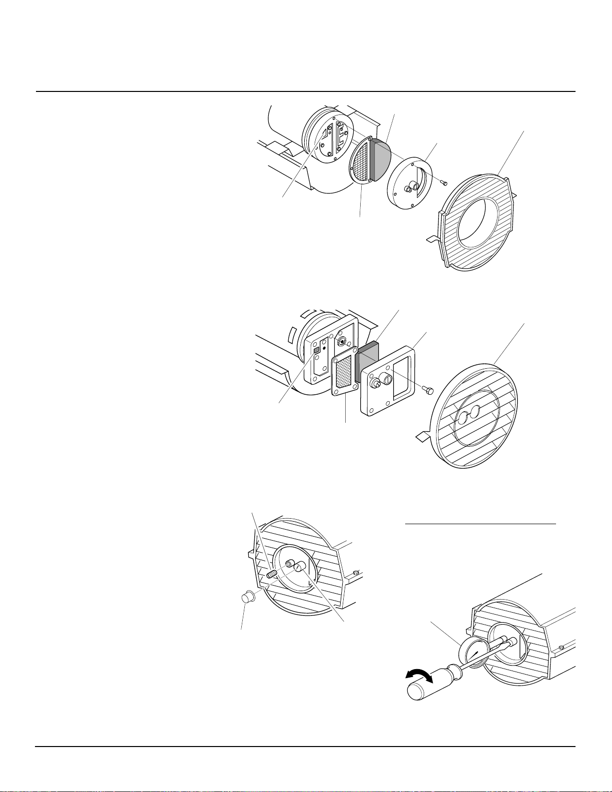
BEDIENUNGSANLEITUNG
WARTUNGSVERFAHREN
(Fortsetzung)
LUFTAUSLASS-, LUFTEINLASSUND STAUBFILTER
1. Oberes Gehäuse entfernen (siehe Seite 8).
2. Die Schrauben der Filterendabdeckung
mit einem 5/16 Zoll Steckschlüssel entfernen.
3. Filterendabdeckung entfernen.
4. Den Luftauslaßfilter und den Staubfilter ersetzen.
5. Den Lufteinlaßfilter waschen oder ersetzen (siehe Regelmäßige Wartung,
Seite 6).
6. Die Filterendabdeckung wieder einbauen.
7. Die Lüfterabdeckung und das obere
Gehäuse wieder einbauen.
WICHTIG:
PUMPENDRUCKEINSTELLUNG
1. Den Druckmesserstopfen von der
2. Den Zusatzgerät-Druckmesser (T eilnr .
3. Das Heizgerät einschalten (Siehe Be-
4. Den Druck einstellen. Das Überdruck-
5. Den Druckmesser entfernen. Den
Die Filter nicht ölen!
Filterendabdeckung entfernen.
HA 118O) einbauen.
dienung, Seite 5). Den Motor auf volle
Drehzahl beschleunigen lassen.
ventil nach rechts drehen, um den
Druck zu erhöhen. Das Überdruckventil nach links drehen, um den Druck zu
verringern. Der korrekte Druck für jedes Modell ist der Spezifikationstabelle
rechts zu entnehmen.
Druckmesserstopfen wieder in die
Filterendabdeckung einbauen.
Lufteinlaßfilter
Lüfterabdeckung
Filterendabdeckung
Staubfilter
Luftauslaßfilter
Abbildung 13 - Luftauslaß-, Lufteinlaß- und Staubfilter, B35CEH und B70CEH Modelle
Lufteinlaßfilter
Filterendabdeckung
Staubfilter
Luftauslaßfilter
Abbildung 14 - Luftauslaß-, Lufteinlaß- und Staubfilter, B100CEH und B150CEH
Modelle
Druckmesserstopfen
Modell (Psi/Bar)
B35CEH 2.9/0,200
B70CEH 4.9/0,338
B100CEH 4.9/0,338
B150CEH 5.5/0,380
Druckmesser
Überdruckventil
Kunststoffkappe
Lüfterabdeckung
Pumpendruck
105398
Abbildung 15 - Entfernen des
Druckmesserstopfens
(Gezeigt sind B35CEH und B70CEH
Modelle)
Abbildung 16 - Einstellen des Pumpendrucks
Bitte umblättern
11
Page 92
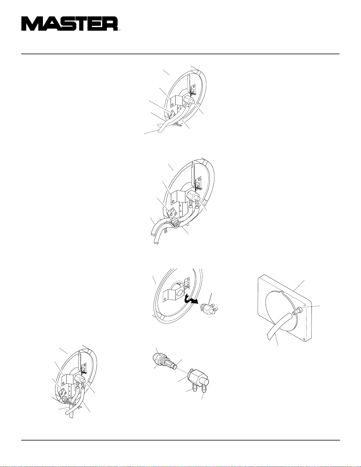
R
TRAGBARE HOCHDRUCK-HEISSLUFTTURBINEN
WARTUNGSVERFAHREN
(Fortsetzung)
DÜSENBAUGRUPPE
1. Das obere Gehäuse entfernen (siehe
Seite 9).
2. Den Lüfter ausbauen (siehe Seite 14).
3. Den Kraftstoff- und Luftschlauch von
der Düsenbaugruppe entfernen (siehe
Abb. 17, 18 oder 19).
4. Die Düsenbaugruppe um eine Viertelumdrehung nach links drehen und in Richtung Motor abziehen (siehe Abb. 20).
5. Das Kunststoff-Sechskantgehäuse in
einen Schraubstock einlegen und leicht
festspannen.
6. Die Düse mit einem 5/8 Zoll Steckschlüssel vorsichtig aus dem Düsenadapter herausschrauben (siehe Abb. 21).
7. Druckluft durch die Düsenvorderseite
blasen. Das entfernt den Schmutz aus
dem Düsenbereich.
8. Die Düsendichtung auf Schäden prüfen.
9. Die Düse in den Düsenadapter einschieben, bis sie sicher sitzt. Die Düse
mit einem 5/8 Zoll Steckschlüssel um
eine 1/3 Umdrehung auf ein Drehmoment von 4,5 bis 5,1 Nm (40 bis 45
Zoll-Pfund) festziehen. Siehe Abb. 21.
10. Die Düsenbaugruppe am Brennergurt
befestigen.
11. Die Kraftstoff- und Luftschläuche an
der Düsenbaugruppe anschließen. Siehe Entfernen der Kraftstoff- und Luftschläuche und Verlegung.
12. Den Lüfter einbauen (siehe Seite 14).
13. Den Lüfterschutz und das obere Gehäuse einbauen (siehe Seite 9).
Brennkammer
Düsenadapterhalterung
Photozellenhalterung
Düsen-/
AdapterBaugruppe
Luftschlauch
Kraftstoffschlauch
Abbildung 17 - Austauschen der Kraftstoff- und Luftleitungen (nur Modelle
B35CEH und B70CEH)
Brennkammer
Düsenadapterhalterung
Luftschlauch
Düsen-/
AdapterBaugruppe
Kraftstoff-
Photozellenhalterung
Figure 18 - Austauschen der Kraftstoffund Luftleitungen (nur Model B100CEH)
Brennkammer
Düsenadapterhalterung
Photozellenhalterung
Luftschlauch
Abbildung 19 - Austauschen der Kraftstoff- und Luftleitungen (nur Model
B150CEH)
Brennkammer
Abbildung 20 - Entfernen der Düsen-/
Adapter-Baugruppe
Düsenvorderseite
Düsendichtung
Düse
Düsenadapter
Luftschlauchfitting
Kraftstoffschlauchfitting
Abbildung 21 - Düse und Düsenadapter
schlauch
Düsen-/
AdapterBaugruppe
Kraftstoffschlauch
Düsen-/
AdapterBaugruppe
ENTFERNEN DER KRAFTSTOFF- UND LUFTSCHLÄU-
CHE UND VERLEGUNG
1. Das obere Gehäuse entfernen (siehe
Seite 9).
2. Die Schrauben der Seitenabdeckung mit
einem 5/16 Zoll Steckschlüssel entfernen.
3. Die Seitenabdeckung entfernen.
4. Die Kraftstoff- und Luftschläuche auf
Risse und/oder Löcher überprüfen.
Wenn der Kraftstoffschlauch beschädigt ist, muß dieser vom Düsenadapter
(siehe Abb. 17, 18 oder 19) und
Kraftstoffilter (siehe Seite 9) abgetrennt
werden. Wenn der Luftschlauch beschädigt ist, muß dieser vom Düsenadapter (siehe Abb. 17, 18 oder 19) und
Stachelanschluß am Pumpendeckel
(siehe Abb. 22) abgetrennt werden.
5. Einen neuen Luft- und/oder Kraftstoffschlauch montieren. Ein Ende des Luftschlauchs am Stachelanschluß des
Pumpendeckels (siehe Abb. 22), das
andere Ende am Düsenadapter befestigen (siehe Abb. 17, 18 oder 19). Ein
Ende des Kraftstoffschlauchs am
Kraftstoffilter (siehe Seite 9) und das
andere Ende am Düsenadapter (siehe
Abb. 17, 18 oder 19) montieren.
Luftschlauch
Stachelanschluß
Luftschlauch
Abbildung 22 - Luftschlauch an Stachelanschluß
12
105398
Page 93

BEDIENUNGSANLEITUNG
WARTUNGSVERFAHREN
(Fortsetzung)
Bei den Heizgerätmodellen B35CEH
und B70CEH müssen die Luft- und
Kraftstoffschläuche wie in Abb. 17 dargestellt verlegt werden.
Hinweis:
Photozellenhalterung nicht berühren.
Beim Heizgerätmodell B100CEH müs-
sen die Luft- und Kraftstoffschläuche wie
in Abb. 18 dar gestellt verlegt werden.
Hinweis:
Photozellenhalterung nicht berühren.
Beim Heizgerätmodell B150CEH müs-
sen die Luft- und Kraftstoffschläuche wie
in Abb. 19 dar gestellt verlegt werden.
Hinweis:
Photozellenhalterung nicht berühren.
6. Die Seitenabdeckung montieren.
7. Das obere Gehäuse und den Lüfterschutz montieren (siehe Seite 9).
PUMPENROTOR
(Verfahren, wenn die Pumpe
festgefressen ist)
1. Das obere Gehäuse entfernen (siehe
Seite 9).
2. Die Filterendabdeckungs-schrauben
mit einem 5/16 Zoll Steckschlüssel entfernen.
3. Die Filterendabdeckung und die Luftfilter entfernen.
4. Die Pumpenplattenschrauben mit einem
5/16 Zoll Steckschlüssel entfernen.
5. Die Pumpenplatte entfernen.
Die Schläuche dürfen die
Die Schläuche dürfen die
Die Schläuche dürfen die
Flügel
6. Den Rotor, den Einsatz und die Flügel
entfernen.
7. Nach Schmutz in der Pumpe suchen.
Wenn Schmutz gefunden wird, die
Pumpe mit Druckluft reinigen.
8. Den Einsatz und den Rotor einbauen.
9. Den Rotorschlitz überprüfen. Bei Bedarf auf 0,076/0,101 mm (0,003/0,004
Zoll) einstellen. (Siehe Abbildung 25).
Hinweis:
Den Rotor eine volle Umdrehung
drehen, um sicherzustellen daß der Schlitz in
der engsten Position 0,076/0,101 mm (0,003/
0,004 Zoll) mißt. Bei Bedarf einstellen.
10. Die Flügel, die Pumpenplatte, die Luft-
filter und die Filterendabdeckung einbauen.
11. Die Lüfterabdeckung und das obere
Gehäuse wieder einbauen.
12. Den Pumpendruck einstellen (siehe
Seite 11).
Hinweis:
Wenn der Rotor noch immer
klemmt, folgendermaßen vorgehen:
13. Die Schritte 1 bis 6 wie oben durchführen.
14. Feines Sandpapier (600 Körnung) auf
einer flachen Oberfläche auflegen. Den
Rotor viermal leicht mit einer “8er-Bewegung” abschmirgeln (siehe Abbildung 26).
15. Den Einsatz und den Rotor wieder einbauen.
16. Die Schritte 10 bis 12 wie oben durchführen.
Flügel
Pumpenplatte
Lufteinlaßfilter
Filterendabdeckung
Einsatz
Rotor
Luftauslaßfilter
Abbildung 24 - Lage des Rotors, B100CEH und B150CEH Modelle
Schlitzstellschraube
Pumpenplatte
Lüfterabdeckung
0,076/0,101
mm (0,003/
0,004 Zoll)
Abstand Mit
Fühllehre
gemessen
Lufteinlaßfilter
Filterendabdeckung
Einsatz
Rotor
Luftauslaßfilter
Abbildung 23 - Lage des Rotors, B35CEH und B70CEH Modelle
105398
13
Lüfterabdeckung
Flügel
Rotor
SchlitzStellschraube
Abbildung 25 - Lage der Schlitz-Stellschrauben
Sandpapier
Abbildung 26 - Abschmirgeln des Rotors
Bitte umblättern
Page 94

R
TRAGBARE HOCHDRUCK-HEISSLUFTTURBINEN
WARTUNGSVERFAHREN
(Fortsetzung)
LÜFTER
WICHTIG:
entfernen, bevor der Motor vom Heizgerät
entfernt wird. Das Gewicht des Motors, das
auf dem Lüfter lastet, könnte die Lüfterflügel verbiegen.
1. Das obere Gehäuse entfernen (siehe
2. Mit einem 1/8 Zoll Inbusschlüssel die
3. Den Lüfter von der Motorwelle schieben.
4. Den Lüfter mit einem weichen, mit
5. Den Lüfter gründlich trocknen lassen.
6. Den Lüfter wieder auf der Motorwelle
7. Die Stellschraube auf dem flachen Teil der
8. Die Lüfterabdeckung und das obere
Stellschraube
Den Lüfter von der Motorwelle
Seite 9).
Schrauben lösen, mit denen der Lüfter
an der Motorwelle befestigt ist.
Kerosin oder einem mit Lösungsmittel
getränkten Tuch reinigen.
anbringen. Die Lüfternabe bündig mit
dem Ende der Motorwelle plazieren
(siehe Abbildung 28).
Welle ansetzen. Die Stellschraube gut festziehen (mit 4,5-5,6 Nm/40-50 Zoll/Pfund).
Gehäuse wieder anbringen.
Lüfter
ZÜNDSTROMANLAGE
WARNUNG: Das Heizgerät
vor den Wartungsarbeiten
ausstecken.
Alte Baugruppe entfernen
1. Mit dem 5/16-Zoll-Steckschlüssel die
vier Schrauben der Seitenabdeckung
entfernen (siehe Abbildung 29).
2. Die neun Drähte von der
Zündstromanlage abnehmen.
3. Mit der Nadelzange die Zunge auf der
Schaltkartenhalterung zusammendrücken und die Kante der
Zündstromanlage nach oben ziehen
(siehe Abbildung 30). Diesen Vorgang bei den anderen vier Schaltkartenhalterungen wiederholen und
danach die Baugruppe entfernen.
Seitenabdeckung
Abbildung 29 – Ausbau der
Abdeckung
Seitenabdeckung
Neue Baugruppe montieren
VORSICHT: Die
Zündstromanlage enthält elektrostatisch geladene Bauteile. Die
Baugruppe an den Kanten der
Schaltkarte anfassen. Keine der
Schnellanschlußklemmen oder
elektronischen Bauteile berühren.
1. Die fünf Löcher in der Baugruppe mit den
fünf Schaltkartenhalterungen in der
Seitenabdeckung ausrichten.
2. Die Baugruppe an den Kanten der
Schaltkarte halten und die Schaltkarte
nach unten drücken, bis alle fünf Zungen an den Schaltkartenhalterungen
einrasten. An der Baugruppe nach oben
ziehen, um sicherzustellen, daß sie eingerastet ist (siehe Abbildung 31).
3. Die neun Kabellitzen an der
Zündsteuerungsbaugruppe wie im
Schaltplan auf Seite 15 dargestellt anschließen.
VORSICHT: Die Anschlüsse
noch einmal überprüfen. Wenn
die Zündstromanlage falsch
angeschlossen wird, können
diese und/oder andere Bauteile
im Heizgerät beschädigt werden.
4. Mit dem 5/16-Zoll-Steckschlüssel die
Seitenabdeckung wieder am Heizgerät
befestigen. Die Schrauben sicher
festziehen, jedoch nicht überziehen!
falsch
Unacceptable Acceptable
richtig
Motorwelle
Abbildung 27 - Lage von Lüfter, Motorwelle und Stellschraube
Lüfter
Bündig
Motorwelle
Stellschraube
Abbildung 28 - Lüfterquerschnitt
Zündstromanlage
Schaltkartenhalterungen (5)
Abbildung 30 – Ausbau der
Schaltkarte
14
Abbildung 31 – Befestigen der
Schaltkarte an den Zungen
105398
Page 95

BEDIENUNGSANLEITUNG
TECHNISCHE DATEN
Heiznennleistung (BTU/Std.) 35.000 70.000 100.000 150.000
Kraftstoff Nur Kerosin oder Heizöl EL benutzen
Kraftstofftank-Fassungsvermögen
(l/U.S. Gal) 11,4/3.0 18,9/5,0 34/9.0 51,1/13.5
Kraftstoffverbrauch
(l/Std., Gal./Std.) 1,1/0,28 1,97/0.52 3,0/0.79 4,1/1.1
Elektrischer Anschluß 230 V/50 Hz (alle Modelle gleich)
Stromstärke (Normalbelastung) 0,8 1,0 1,2 1,2
Heißluftausstoß
3
(m
/min. / Kubikfuß/min.) 4/140 6,4/225 12/425 14,2/500
U/min 1425 2850 2850 2850
SCHALTPLAN
1b
1
1a
(2)(1)
(3) (4) (6)
(N)
(5)
(7)
(8)
105398
15
Page 96

R
TRAGBARE HOCHDRUCK-HEISSLUFTTURBINEN
BEBILDERTE
ERSATZTEILLISTE
B35CEH MODELL
4
5
36
3
9
7
8
22
6
21
26
10
20
1
2
9-1
9-2
9-6
9-5
11
9-4
9-3
12
18
23
16
24
13
12-18
12-17
12-1
12-16
12-2
12-3
12-15
12-4
12-14
17
12-5
19
12-6
35
12-7
28
30
29
32
33
37
39
27
38
31
25
34
15
14
43
41
40
42
12-8
12-9
12-13
12-10
Motor- und Pumpenbaugruppe
12-12
16
12-19
12-11
105398
Page 97

BEDIENUNGSANLEITUNG
ERSATZTEILKATALOG
Dieser Katalog enthält die Ersatzteile für Ihr Heizgerät. Bei der Bestellung von Ersatzteilen
ist es wichtig, daß Sie die entsprechenden Modell- und Seriennummern (vom Modellschild), gefolgt von der Ersatzteilnummer und der Beschreibung des gewünschten Teiles
angeben.
B35CEH MODELL
KENNNR. TEILNUMMER BESCHREIBUNG STÜCK
1 M51104-01 Handgriff 1
2 098511-256 Oberes Gehäuse 1
3 M11084-29 Schraube, #10-16 x 3/4 Zoll 2
4 102432-01 Schraube/Federring, 1/2 Zoll 6
5 098512-63 Brennkammer 1
6 M10908-2 Schraube, #6-32 x 3/8 Zoll 2
7 103154-03 Photozellenhalterung 1
8 M16656-24 Photozellen-Baugruppe 1
9 ** Brennerhalterung-Baugruppe 1
9-1 HA3006 Düsenbaugruppe 1
9-2 102548-05 Zündersatz 1
9-3 104056-01 Düsenadapter 1
9-4 102336-01 Düsenadapterhalterung 1
9-5 M10908-75 Schraube, #6-32 x 7/8 Zoll 1
9-6 103347-01 Tellerfeder 1
10 102431-01 Schraube/Federring, 1/2 Zoll 2
11 103684-01 Lüfter 1
12 ** Motor- und Pumpenbaugruppe 1
12-1 102001-25 Motor 1
12-2 079975-03 Pumpengehäuse 1
12-3 M22009 Einsatz 1
12-4 M22456-2 Rotor 1
12-5 M29608 Pumpendeckel 1
12-6 M29632 Staubfilter 1
12-7 M29633 Einlaßfilter 1
12-8 M29609 Filterendabdeckung 1
12-9 M12461-31 Schraube, #10-32 x 1 Zoll 3
12-10 M27694 Stellschraube 1
12-11 M10993-1 Druckentlastungsfeder 1
12-12 M22997 Stopfen 1
12-13 M8940 Stahlkugel (1/4 Zoll Durchm) 1
12-14 M29612-01 Auslaßfilter 1
12-15 M12461-32
12-16 103676-01 Winkelstück, 90° (Fitting) 1
12-17 M8643-2 Flügel 4
12-18 FHPF3-6C Schraube, #10-32 x 3/4 Zoll 2
12-19 105780-01 Kunststoffkappe 1
13 M51105-01 Lüfterabdeckung 1
Schraube, #10-32 x 1 1/8 Zoll
KENNNR. TEILNUMMER BESCHREIBUNG STÜCK
14 079673-07 Netzkabel 1
15 M50400 Entlastungsmuffe 1
16 NTC-4C Sechskant-Sicherungsmutter 2
17 102431-01 Schraube/Federring, 1/2 Zoll 4
18 M50631 Gummistoßdämpferr 2
19 097461-09 Seitenabdeckung 1
20 101205-01 Motoraufhängung 1
21 M30865-02 Buchse 1
22 M11271-8 Klemmutter 6
23 M50104-02 Buchse (Drähte) 1
24 102431-01 Schraube/Federring, 1/2 Zoll 6
25 RF3-4B Schraube, #10-32 x 1/2 Zoll 1
26 098511-237 Unteres Gehäuse 1
27 M50814-06 Gummi-Luftschlauch 1
28 M29652-05 Kraftstoffschlauch 1
29 108060-01 Kraftstoffilterbaugruppe 1
30 M10990-3 Gummibuchse 1
31 102861-01 Nylongegenmutter 1
32 102349-01 Leiterplatten-Halterschraube 5
33 104068-04 Zündstromanlage 1
34 097702-01 Kraftstofftankdeckel 1
35 108088-01 Kraftstofftank 1
36 M51108-01 Hitzeschild 1
37 NPF-3B Mutter, #10-32 3
38 097785-01 Vinylschaumdichtung 1
39 WLE-3 Federring, #10 1
40 079010-39 Verdrahtung (Braun) 1
41 105793-01 EIN-/AUS-Schalter 1
42 079919-01 Schalterabdeckung 1
43 079010-40 Verdrahtung (Weiß)1
ERHÄLTLICHE TEILE - NICHT GEZEIGT
6
HA2210 Einfüllstutzensieb 1
103814-01 Drahtschließe1
097649-01 Modellschild 2
106013-01 Aufkleberpackung 1
105880-01 Sicherung 1
**Nicht als vollständige Baugruppe erhältlich. Teile einzeln bestellen.
105398
17
Page 98

R
TRAGBARE HOCHDRUCK-HEISSLUFTTURBINEN
BEBILDERTE
ERSATZTEILLISTE
B70CEH MODELL
4
5
36
3
9
7
8
22
6
21
26
10
20
1
2
9-1
9-2
9-6
9-5
11
9-4
9-3
12
18
23
16
24
13
12-18
12-17
12-1
12-16
12-2
12-3
12-15
12-4
12-14
17
12-5
19
12-6
35
32
12-7
12-8
12-9
28
30
29
33
12-13
12-10
31
37
39
27
38
25
34
15
14
43
41
40
42
Motor- und Pumpenbaugruppe
12-12
18
12-19
12-11
105398
Page 99

BEDIENUNGSANLEITUNG
ERSATZTEILKATALOG
Dieser Katalog enthält die Ersatzteile für Ihr Heizgerät. Bei der Bestellung von Ersatzteilen
ist es wichtig, daß Sie die entsprechenden Modell- und Seriennummern (vom Modellschild), gefolgt von der Ersatzteilnummer und der Beschreibung des gewünschten Teiles
angeben.
B70CEH MODELL
KENNNR. TEILNUMMER BESCHREIBUNG STÜCK
1 M51104-01 Handgriff 1
2 098511-256 Oberes Gehäuse 1
3 M11084-29 Schraube, #10-16 x 3/4 Zoll 2
4 102432-01 Schraube/Federring, 1/2 Zoll 6
5 098512-64 Brennkammer 1
6 M10908-2 Schraube, #6-32 x 3/8 Zoll 2
7 103154-03 Photozellenhalterung 1
8 M16656-24 Photozellen-Baugruppe 1
9 ** Brennerhalterung-Baugruppe 1
9-1 HA3026 Düsenbaugruppe 1
9-2 102548-05 Zündersatz 1
9-3 104056-01 Düsenadapter 1
9-4 102336-01 Düsenadapterhalterung 1
9-5 M10908-75 Schraube, #6-32 x 7/8 Zoll 1
9-6 103347-01 Tellerfeder 1
10 102431-01 Schraube/Federring, 1/2 Zoll 2
11 103684-01 Lüfter 1
12 ** Motor- und Pumpenbaugruppe 1
12-1 102001-23 Motor 1
12-2 079975-02 Pumpengehäuse 1
12-3 M22009 Einsatz 1
12-4 M22456-1 Rotor 1
12-5 M29608 Pumpendeckel 1
12-6 M29632 Staubfilter 1
12-7 M29633 Einlaßfilter 1
12-8 M29609 Filterendabdeckung 1
12-9 M12461-31 Schraube, #10-32 x 1 Zoll 3
12-10 M27694 Stellschraube 1
12-11 M10993-1 Druckentlastungsfeder 1
12-12 M22997 Stopfen 1
12-13 M8940 Stahlkugel (1/4 Zoll Durchm) 1
12-14 M29612-01 Auslaßfilter 1
12-15 M12461-31 Schraube, #10-32 x 1
12-16 103676-01 Winkelstück, 90° (Fitting) 1
12-17 M8643 Flügel 4
12-18 FHPF3-5C Schraube, #10-32 x 5/8 Zoll 2
12-19 105780-01 Kunststoffkappe 1
13 M51105-01 Lüfterabdeckung 1
1
/8 Zoll 6
KENNNR. TEILNUMMER BESCHREIBUNG STÜCK
14 079673-07 Netzkabel 1
15 M50400 Entlastungsmuffe 1
16 NTC-4C Sechskant-Sicherungsmutter 2
17 102431-01 Schraube/Federring, 1/2 Zoll 4
18 M50631 Gummistoßdämpferr 2
19 097461-09 Seitenabdeckung 1
20 101205-01 Motoraufhängung 1
21 M30865-02 Buchse 1
22 M11271-8 Klemmutter 6
23 M50104-02 Buchse (Drähte) 1
24 102431-01 Schraube/Federring, 1/2 Zoll 6
25 RF3-4B Schraube, #10-32 x 1/2 Zoll 1
26 098511-237 Unteres Gehäuse 1
27 M50814-06 Gummi-Luftschlauch 1
28 M29652-05 Kraftstoffschlauch 1
29 108060-03 Kraftstoffilterbaugruppe 1
30 M10990-3 Gummibuchse 1
31 102861-01 Nylongegenmutter 1
32 102349-01 Leiterplatten-Halterschraube 5
33 104068-04 Zündstromanlage 1
34 097702-01 Kraftstofftankdeckel 1
35 108088-03 Kraftstofftank 1
36 M51108-01 Hitzeschild 1
37 NPF-3B Mutter, #10-32 3
38 097785-01 Vinylschaumdichtung 1
39 WLE-3 Federring, #10 1
40 079010-39 Verdrahtung (Braun) 1
41 105793-01 EIN-/AUS-Schalter 1
42 079919-01 Schalterabdeckung 1
43 079010-40 Verdrahtung (Weiß)1
ERHÄLTLICHE TEILE - NICHT GEZEIGT
HA2210 Einfüllstutzensieb 1
103814-01 Drahtschließe1
097649-01 Modellschild 2
106013-02 Aufkleberpackung 1
105880-01 Sicherung 1
**Nicht als vollständige Baugruppe erhältlich. Teile einzeln bestellen.
105398
19
Page 100

R
TRAGBARE HOCHDRUCK-HEISSLUFTTURBINEN
BEBILDERTE
ERSATZTEILLISTE
B100CEH MODELL
2
1
3
7-4
7
4
6
24
28
5
8
11
23
20
22
19
25
18
9
10
12
15
26
27
7-1
7-2
7-6
7-3
7-5
16
29
10-1
10-2
10-3
10-4
10-17
10-16
10-15
10-13
10-14
Motor- und Pumpenbaugruppe
10-5
10-13
35
10-6
30
43
36
32
21
31
14
17
41
42
37
13
33
34
44
39
38
14
40
10-7
10-8
10-9
10-10
10-11
10-12
20
105398
 Loading...