

Page 1
R
PORTABLE
FORCED
AIR HEATERS
OWNER’S MANUAL
Heater Sizes: 35,000 70,000 100,000 150,000 Btu/Hr
Models: B35CEA, B70CEA, B100CEA, and B150CEA
IMPORTANT: Read and understand this manual before assembling, starting or
servicing heater. Improper use of heater can cause serious injury. Keep this manual
for future reference.
Page 2

R
PORTABLE FORCED AIR HEATERS
SAFETY
INFORMATION
WARNINGS
IMPORTANT: Read this Owner’s
Manual carefully and completely
before trying to assemble, operate, or service this heater. Improper use of this heater can
cause serious injury or death from
burns, fire, explosion, electrical
shock, and carbon monoxide
poisoning.
DANGER: Carbon monoxide
poisoning may lead to death!
Carbon Monoxide Poisoning: Early
signs of carbon monoxide poisoning resemble the flu, with headaches, dizziness,
and/or nausea. If you have these signs, the
heater may not be working properly. Get
fresh air at once! Have heater serviced.
Some people are more affected by carbon
monoxide than others. These include pregnant women, persons with heart or lung
disease or anemia, those under the influence
of alcohol, and those at high altitudes.
Make certain you read and understand all
Warnings. Keep this manual for reference.
It is your guide to safe and proper operation
of this heater.
• Use only kerosene or No. 1 fuel oil to
avoid risk of fire or explosion. Never use
gasoline, naphtha, paint thinners, alcohol, or other highly flammable fuels.
• Fueling
a) Personnel involved with fueling shall
be qualified and thoroughly familiar
with the manufacturer's instructions
and applicable regulations regarding the safe fueling of heating units.
b)Only the type of fuel specified on the
heater's data plate shall be used.
c) All flame, including the pilot light, if
any, shall be extinguished and the heater
allowed to cool, prior to fueling.
d)During fueling, all fuel lines and fuel-
line connections shall be inspected for
leaks. Any leaks shall be repaired prior
to returning the heater to service.
e) At no time shall more than one day's
supply of heater fuel be stored inside
a building in the vicinity of the heater.
Bulk fuel storage shall be outside the
structure.
f) All fuel storage shall be located a
minimum of 762cm (25 feet) from
heaters, torches, welding equipment,
and similar sources of ignition (exception: the fuel reservoir integral
with the heater unit).
g)Whenever possible, fuel storage shall
be confined to areas where floor penetrations do not permit fuel to drip
onto or be ignited by a fire at lower
elevation.
h)Fuel storage shall be in accordance
with the authority having jurisdiction.
• Never use heater where gasoline, paint
thinner, or other highly flammable vapors are present.
• Follow all local ordinances and codes
when using heater.
• Heaters used in the vicinity of tarpaulins, canvas, or similar enclosure materials shall be located a safe distance
from such materials. The recommended
minimum safe distance is 304.8cm (10
feet). It is further recommended that
these enclosure materials be of a fire
retardant nature. These enclosure materials shall be securely fastened to prevent them from igniting or from upsetting the heater due to wind action.
• Use only in well-vented areas. Before
using heater, provide at least a 2800
square cm (three-square-foot) opening
of fresh, outside air for each 100,000
Btu/Hr of rating.
• Use only in places free of flammable
vapors or high dust content.
• Use only the electrical voltage and frequency specified on model plate.
• Use only a three-prong, grounded extension cord.
• Minimum heater clearances from combustibles:
Outlet: 250 cm (8 Ft.)
Sides, Top, and Rear: 125 cm (4 Ft.)
• Locate heater on a stable and level surface if heater is hot or running or a fire
may occur.
• When moving or storing heater, keep
heater in a level position or fuel spillage may occur.
• Keep children and animals away from
heater.
• Unplug heater when not in use.
• When used with thermostat, heater may
start anytime.
• Never use heater in living or sleeping
areas.
• Never block air inlet (rear) or air outlet
(front) of heater.
• Never move, handle, refuel, or service
a hot, operating, or plugged-in heater.
• Never attach duct work to front or rear
of heater. Using duct work could reduce
the necessary air flow of heater. Heater
would produce excessive carbon monoxide.
2
104468
Page 3
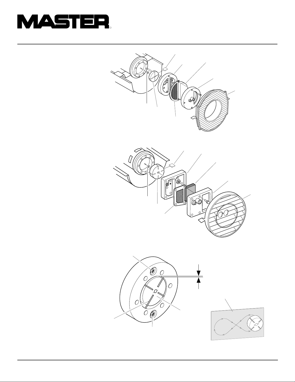
OWNER’S MANUAL
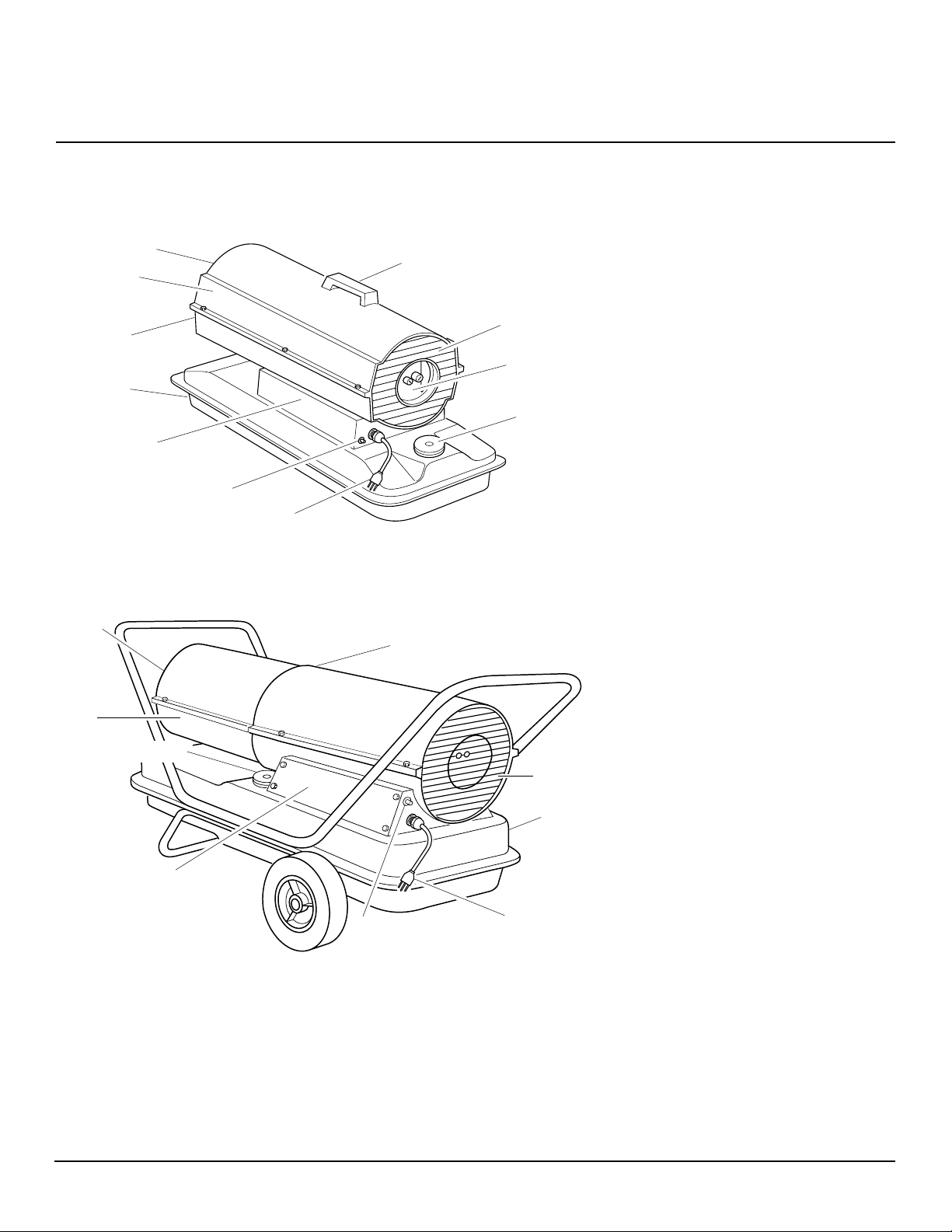
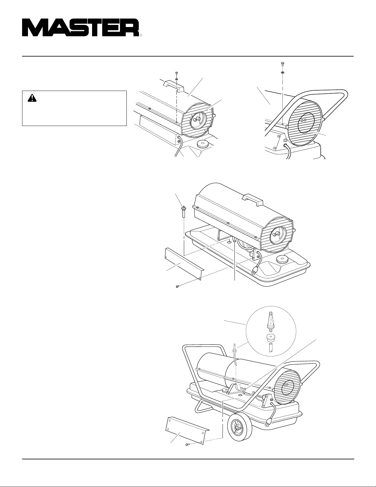
PRODUCT
IDENTIFICATION
Hot Air Outlet
Upper Shell
Lower Shell
Fuel Tank
Side Cover
Flame-Out
Control Reset
Button
Figure 1 - 35/70,000 Btu/Hr Models
Hot Air
Outlet
Power
Cord
Handle
Upper Shell
UNPACKING
1. Remove all packing items applied to
heater for shipment.
2. Remove all items from carton.
3. Check items for any shipping damage.
If heater is damaged, promptly inform
dealer where you bought heater.
Fan Guard
Air Filter
End Cover
Fuel Cap
Lower
Shell
Fuel Cap
Side Cover
Figure 2 - 100/150,000 Btu/Hr Models
Flame-Out
Control Reset Button
Fan Guard
Fuel Tank
Power Cord
104468
3
Page 4

R
PORTABLE FORCED AIR HEATERS
ASSEMBLY
(FOR 100,000 AND 150,000
BTU/HR MODELS ONLY)
These models are furnished with wheels and
handles. Wheels, handles, and the mounting
hardware are found in the shipping carton.
Tools Needed
• Medium Phillips Screwdriver
• 3/8" Open or Adjustable Wrench
• Hammer
1. Slide axle through wheel support
frame. Install wheels on axle.
IMPORTANT:
wheels, point extended hub of wheels
toward wheel support frame (see Figure 3).
When installing
2. Place cap nuts on axle ends. Gently tap
with hammer to secure.
3. Place heater on wheel support frame.
Make sure air inlet end (rear) of heater
is over wheels. Line up holes on fuel
tank flange with holes on wheel support frame.
4. Place front handle and rear handle on
top of fuel tank flange. Insert screws
through handles, fuel tank flange, and
wheel support frame. Attach nut finger
tight after each screw is inserted.
5. After all screws are inserted, tighten
nuts firmly.
Front Handle
FUELS
WARNING: Use only kerosene
or No. 1 fuel oil to avoid risk of fire
or explosion. Never use gasoline, naphtha, paint thinners, alcohol or other highly flammable
fuels.
Do not use heavy fuels such as No. 2 fuel oil
or No. 2 Diesel. Using heavy fuels will
result in:
• clogged fuel filter and nozzle
• carbon build up on spark plug
• use of non-toxic anti-icer in fuel during
very cold weather
IMPORTANT:
container. Be sure storage container is clean.
Foreign matter such as rust, dirt, or water
will cause the flame-out control to shut
down heater. Foreign matter may also require you to clean fuel system often.
Use a KEROSENE ONLY
Hot Air
Outlet
Fuel Tank
Flange
Wheel
Support
Frame
Wheel
Cap Nut
Screw
Nut
Axle
Extended
Hub
Rear
Handle
Air
Inlet
VENTILATION
WARNING: Follow the minimum fresh, outside air ventilation requirements. If proper fresh,
outside air ventilation is not provided, carbon monoxide poisoning can occur. Provide proper
fresh, outside air ventilation before running heater.
Provide a fresh air opening of at least 2800
square cm (three square feet) for each
100,000 Btu/Hr rating. Provide extra fresh
air if more heaters are being used.
Example:
quires one of the following:
• a 4.88 m (16 foot) wide two-car garage
door raised 8.59 cm (3.38 inches)
• a 2.75 m (9 foot) wide single-car garage
door raised 15.24 cm (six inches)
• two, 76.2 cm (thirty-inch) windows
raised 30.48 cm (twelve inches)
A 150,000 Btu/Hr heater re-
Figure 3 - Wheel and Handle Assembly, 100/150,000 Btu/Hr Models Only
4
104468
Page 5
OWNER’S MANUAL
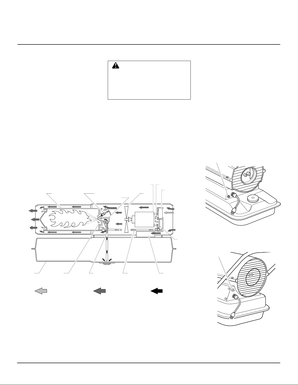
THEORY OF
OPERATION
The Fuel System: The air pump forces
air through the air line. The air is then
pushed through the burner head nozzle. This
air causes fuel to lift from the tank. A fine
mist of fuel is sprayed into the combustion
chamber.
The Air System: The motor turns the fan.
The fan pushes air into and around the
combustion chamber. This air is heated and
provides a stream of clean, hot air.
The Ignition System: The electronic
ignitor sends voltage to the spark plug. The
spark plug ignites the fuel and air mixture.
The Flame-Out Control System: This
system causes the heater to shut down if the
flame goes out.
Combustion
Chamber
Spark
Plug
OPERATION
WARNING: Review and understand the warnings in the
Safety Information Section. They
are needed to safely operate this
heater. Follow all local codes
when using this heater.
To Start Heater
1. Follow all ventilation and safety information.
2. Fill fuel tank with kerosene or No. 1
fuel oil.
3. Attach fuel cap.
4. Plug power cord of heater into standard
230 volt/50 hertz, grounded (earthed)
outlet. Use an extension cord if needed.
Use only a three-prong, grounded
(earthed) extension cord.
Air Pump
Intake
Air
Filter
Burner
Head
Motor
Fan
Extension Cord Wire Size
Requirements
Up to 30.5 meters (100 feet) long, use 1.0
2
mm
(16 AWG) conductor 30.6 to 61 meters
(101 to 200 feet) long, use 1.5 mm2 (14
AWG) conductor
Heater will start when power cord is plugged
into outlet. If not, push in flame-out control
reset button (see Figures 5 and 6).
To Stop Heater
1. Unplug power cord from outlet.
To Restart Heater
1. Wait 2 minutes after stopping heater.
2. Repeat steps under To Start Heater.
Flame-Out Control
Reset Button
Clean
Heated
Air Out
Fuel
Tank
Figure 4 - Cross Section Operational View
Nozzle
Air For Fuel
System
Fuel
Filter
Air line
To Burner
Air For Combustion
And Heating
Cool
Air
In
Output
Air
Filter
Electronic
Ignitor
Fuel
Figure 5 - Flame-Out Control Reset
Button, 35/70,000 Btu/Hr
Flame-Out Control
Reset Button
Figure 6 - Flame-Out Control Reset
Button, 100/150,000 Btu/Hr
104468
5
Page 6

R
PORTABLE FORCED AIR HEATERS
STORING,
TRANSPORTING,
OR SHIPPING
Note:
If shipping, transport companies re-
quire fuel tanks to be empty.
1. Drain fuel tank.
Note:
Some models have drain plug on
underside of fuel tank. If so, remove
drain plug to drain all fuel. If heater
does not have drain plug, drain fuel
through fuel cap opening. Be sure all
fuel is removed.
2. Replace drain plug if provided.
3. If any debris is noted in old fuel, add 1
or 2 quarts of clean kerosene to tank,
stir, and drain again. This will prevent
excess debris from clogging filters during future use.
4. Replace fuel cap or drain plug. Properly dispose of old and dirty fuel. Check
with local automotive service stations
that recycle oil.
5. If storing, store heater in dry place.
Make sure storage place is free of dust
and corrosive fumes.
IMPORTANT:
summer months for use during next heating
season. Using old fuel could damage heater.
Do not store kerosene over
PREVENTATIVE
MAINTENANCE
SCHEDULE
Item
Fuel tank
Air output and
lint filters
Air intake filter
Fuel filter
Spark plug
Fan blades
Motor
How Often
Flush every 150-200 hours of operation or as needed.
Replace every 500 hours of, operation or once a year.
Wash and dry with soap and water
every 500 hours of operation or as
needed.
Clean twice a heating season or as
needed.
Clean and regap every 600 hours
operation or replace as needed.
Clean every season or as needed.
Not required/permanently lubricated
WARNING: Never service heater while
it is plugged in, operating, or hot. Severe
burns and electrical shock can occur.
How To
See Storing, Transporting or
Shipping,column 1
See Air Output, Air Intake,
and Lint Filters, page 10.
See Air Output, Air Intake,
and Lint Filters, page 10.
See Fuel Filter, page 8.
See Spark Plug, page 9.
See Fan, page 13.
6
104468
Page 7
OWNER’S MANUAL
TROUBLESHOOTING
OBSERVED FAULT
Heater ignites, but flame-out control shuts
off heater after a short period of time.
Heater will not ignite, but motor runs for a
short period of time.
WARNING: Never service heater while it is plugged in, operating,
or hot. Severe burns and electrical shock can occur.
POSSIBLE CAUSE
1. Wrong pump pressure
2. Dirty air output, air intake, and lint filters
3. Dirty fuel filter
4. Dirt in nozzle
5. Dirty photocell lens
6. Bad flame-out control
1. Wrong pump pressure
2. Carbon deposits on spark plug and/or
improper gap
3. Dirty fuel filter
4. Dirt in nozzle
5. Water in fuel tank
WARNING: High voltage!
REMEDY
1. See Pump Pressure
Adjustment, page 10.
2. See Air Output, Air Intake and Lint Filters, page 10.
3. See Fuel Filter, page 8.
4. See Nozzle, page 11.
5. Clean photocell lens.
6. Replace flame-out control.
1. See Pump Pressure Adjustment, page 10.
2. See Spark Plug, page 9.
3. See Fuel Filter, page 8.
4. See Nozzle, page 11.
5. Drain and flush fuel tank with clean
kerosene. See Storing, Transporting, or
Shipping, page 6.
Motor does not start when heater is plugged
in, fan rotates slowly or does not turn.
6. Electronic ignitor not grounded (earthed)
7. Bad electronic ignitor
1. Flame-out control not reset
2. Binding pump rotor
6. Make sure electronic ignitor mounting
is tight.
7. Replace electronic ignitor.
1. Reset flame-out control button, see Figures 5 and 6, page 5.
2. If fan is hard to turn, see Pump Rotor,
page 12.
104468
7
Page 8
R
PORTABLE FORCED AIR HEATERS
SERVICE
PROCEDURES
WARNING: Never service
heater while it is plugged in, operating, or hot. Severe burns and
electrical shock can occur.
Upper Shell Removal
1. Remove screws and lock washers along
each side of heater using 5/16" nutdriver. These screws attach upper and
lower shells together.
2. Lift upper shell off.
3. Remove fan guard.
Fuel Filter
(35/70,000 Btu/Hr Models)
1. Remove side cover screws using 5/16"
nut-driver.
2. Remove side cover.
3. Pull rubber fuel line off fuel filter neck.
4. Carefully pry bushing and fuel filter out
of fuel tank.
5. Wash fuel filter with clean fuel and replace in tank.
6. Attach rubber fuel line to fuel filter
neck.
7. Replace side cover.
Fuel Filter
(100/150,000 Btu/Hr Models)
1. Remove side cover screws using 5/16"
nut-driver.
2. Remove side cover.
3. Pull upper fuel line off fuel filter neck.
4. Carefully pry bushing, lower fuel line,
and fuel filter out of fuel tank.
5. Wash fuel filter with clean fuel and replace in tank.
6. Attach upper fuel line to fuel filter neck.
7. Replace side cover.
Upper Shell
Fan Guard
Figure 7 - Upper Shell Removal, 35/70,000
Btu/Hr Models
Fuel Filter
Side Cover
Fuel Line
Figure 9 - Fuel Filter Removal, 35/70,000 Btu/Hr Models
Fuel Filter, Bushing, and
Lower Fuel Line
Upper
Shell
Figure 8 - Upper Shell Removal, 100/
150,000 Btu/Hr Models
Fan
Guard
Upper
Fuel
Line
Side Cover
Figure 10 - Fuel Filter Removal, 100/150,000 Btu/Hr Models
8
104468
Page 9
OWNER’S MANUAL
SERVICE
PROCEDURES
Continued
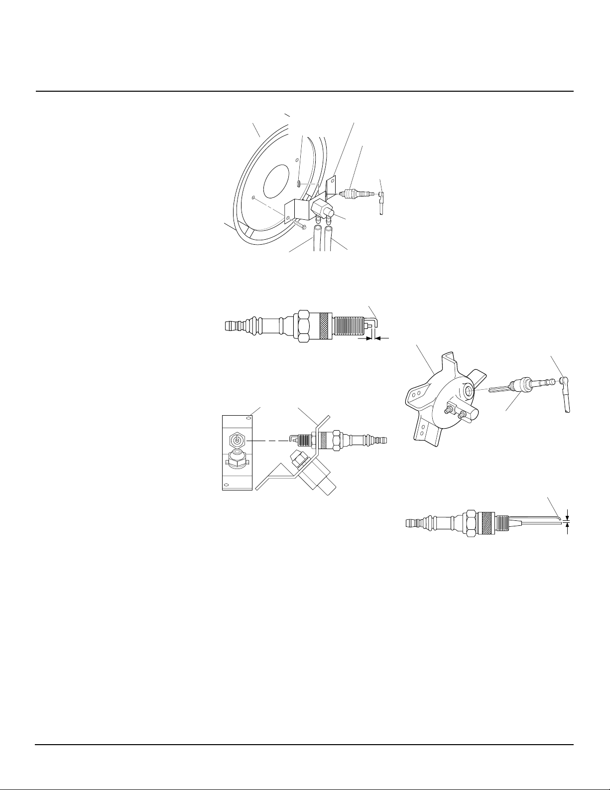
Spark Plug
(35,000 Btu/Hr Model)
1. Remove upper shell (see page 8).
2. Remove fan (see page 13).
3. Remove fuel and air line
hoses from nozzle assembly.
4. Remove spark plug wire from spark plug.
5. Remove two screws using 5/16" nutdriver and remove burner strap.
6. Place hex-body of spark plug into vise
and tighten.
7. Remove spark plug mounting nut using 11/16" open-end wrench.
8. Remove burner strap from spark plug.
9. Clean and regap spark plug electrodes
to 1.4 mm (.055") gap.
10. Replace burner strap onto spark plug.
Rotate burner strap to position spark
plug electrodes (see Figure 13).
11. Tighten spark plug with spark plug
mounting nut.
12. Release hex-body of spark plug from vise.
13. Replace burner strap onto combustion
chamber.
14. Attach spark plug wire to spark plug.
15. Attach fuel and air line hoses to nozzle
assembly.
16. Replace fan (see page 13).
17. Replace fan guard and upper shell.
Combustion
Chamber
Air Line Hose
Figure 11 - Spark Plug Removal, 35,000
Btu/Hr Model
Figure 12 - Spark Plug Gap, 35,000 Btu/Hr
Model
Burner Strap
Figure 13 - Spark Plug Rotation, 35,000
Btu/Hr Model Only
Spark Plug
Mounting Nut
Burner
Strap
Spark
Plug
Spark
Plug
Wire
Nozzle
Assembly
Fuel Line Hose
Bend Here to
Adjust Gap
1.4 mm
(.055") Gap
Spark Plug
(70/100/150,000 Btu/Hr Models)
1. Remove upper shell (see page 8).
2. Remove fan (see page 13).
3. Remove spark plug wire from spark plug.
4. Remove spark plug from burner head
using 13/16" open-end wrench.
5. Clean and regap spark plug electrodes
as follows:
70/100,000 Btu/Hr Models:
1.9 mm (.075") gap
150,000 Btu/Hr Model:
2.8 mm (.110") gap
6. Install spark plug in burner head.
7. Attach spark plug wire to spark plug.
8. Replace fan (see page 13).
9. Replace fan guard and upper shell.
Burner Head
Spark Plug Wire
Spark
Plug
Figure 14 - Spark Plug Removal, 70/100/
150,000 Btu/Hr Models
Bend Here to
Adjust Gap
Gap
Figure 15 - Spark Plug Gap, 70/100/150,000
Btu/Hr Models
104468
Continued
9
Page 10
R
PORTABLE FORCED AIR HEATERS
SERVICE
PROCEDURES
Continued
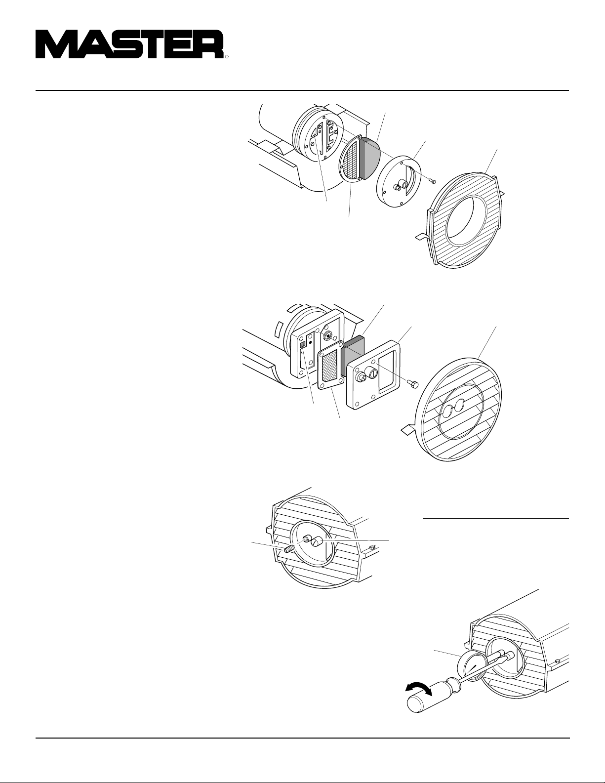
Air Output, Air Intake, and Lint
Filters
1. Remove upper shell (see page 8).
2. Remove filter end cover screws using
5/16" nut-driver.
3. Remove filter end cover.
4. Replace air output and lint filters.
5. Wash or replace air intake filter (see
Preventative Maintenance Schedule,
page 6).
6. Replace filter end cover.
7. Replace fan guard and upper shell.
IMPORTANT:
Pump Pressure Adjustment
1. Remove pressure gauge plug from filter
end cover.
2. Install accessory pressure gauge (part
number HA1180).
3. Start heater (see Operation, page 5).
Allow motor to reach full speed.
4. Adjust pressure. Turn relief valve to
right to increase pressure. Turn relief
valve to left to decrease pressure. See
specifications at right for correct pressure for each model.
5. Remove pressure gauge. Replace pressure gauge plug in filter end cover.
Do not oil filters
Air Intake Filter
Filter End
Cover
Lint Filter
Air Output
Filter
Figure 16 - Air Output, Air Intake, and Lint Filters, 35/70,000 Btu/Hr Models
Air Intake Filter
Filter End
Cover
Lint Filter
Air Output
Filter
Figure 17 - Air Output, Air Intake, and Lint Filters, 100/150,000 Btu/Hr Models
Fan Guard
Fan Guard
Model Pump Pressure
(PSI/Bar)
Pressure
Gauge
Plug
Relief
Valve
35,000 Btu/Hr 2.9/0.20
70,000 Btu/Hr 3.8/0.26
100,000 Btu/Hr 3.9/0.27
150,000 Btu/Hr 4.8/0.33
Figure 18 - Pressure Gauge Plug Removal
(35/70,000 Btu/Hr Models Shown)
10
Pressure
Gauge
Figure 19 - Adjusting Pump Pressure
104468
Page 11
OWNER’S MANUAL
SERVICE
PROCEDURES
Continued
Nozzle
(35,000 Btu/Hr Model)
1. Remove upper shell (see page 8).
2. Remove fan (see page 13).
3. Remove fuel and air line hoses from
nozzle assembly.
4. Turn nozzle assembly 1/4 turn to left
and pull toward motor to remove.
5. Place plastic hex-body into vise and
lightly tighten.
6. Carefully remove nozzle from the
nozzle adapter using 5/8" socket
wrench.
7. Blow compressed air thru face of nozzle.
This will free any dirt in nozzle area.
8. Inspect nozzle seal for damage.
9. Replace nozzle into nozzle adapter until nozzle seats. Tighten 1/3 turn more
using 5/8" socket wrench (4.5-5.1 n-m/
40-45 inch-pounds).
10. Attach nozzle assembly to burner strap.
11. Attach fuel and airline hoses to nozzle
assembly.
12. Replace fan (see page 13).
13. Replace fan guard and upper shell.
Combustion
Chamber
Nozzle
Assembly
Fuel Line
Air Line Hose
Figure 20 - Removing Air and Fuel Line
Hoses, 35,000 Btu/Hr Model
Hose
Burner
Strap
Nozzle
Assembly
Figure 21 - Removing Nozzle Assembly,
35,000 Btu/Hr Model
Nozzle
Face
Nozzle
Air line Fitting
Figure 22 - Nozzle and Nozzle Adapter,
35,000 Btu/Hr Model
Nozzle Seal
Nozzle
Adapter
Fuel line Fitting
Nozzle
(70/100/150,000 Btu/Hr Models)
1. Remove upper shell (see page 8).
2. Remove fan (see page 13).
3. Remove fuel and air line hoses from
burner head.
4. Remove spark plug wire from spark plug.
5. Remove spark plug from burner head
using 13/16" open-end wrench.
6. Remove three screws using 5/16" nutdriver and remove burner head from
combustion chamber.
7. Place burner head into vise and lightly
tighten.
8. Carefully remove nozzle from burner
head using 5/8" socket wrench (see Figure 24).
9. Blow compressed air thru face of nozzle.
This will free any dirt in nozzle area.
10. Inspect nozzle seal for damage.
11. Replace nozzle into burner head and
tighten firmly (9.1-12.4 n-m/80-110
inch-pounds).
12. Attach burner head to combustion
chamber.
13. Install spark plug in burner head.
14. Attach spark plug wire to spark plug.
15.
Attach fuel and airline hoses to burner head.
16. Replace fan (see page 13).
17. Replace fan guard and upper shell.
Combustion
Chamber
Screw
Air Line Hose
Figure 23 - Removing Burner Head,
70/100/150,000 Btu/Hr Models
Nozzle
Face
Nozzle
Burner
Head
Figure 24 - Removing Nozzle, 70/100/
150,000 Btu/Hr Models
Burner
Head
Fuel Line Hose
Nozzle
Seal
Spark Plug
Wire
Spark
Plug
Air line
Fitting
Fuel line
Fitting
104468
Continued
11
Page 12
R
PORTABLE FORCED AIR HEATERS
SERVICE
PROCEDURES
Continued
Pump Rotor
(Procedure if rotor is binding)
1. Remove upper shell (see page 8).
2. Remove filter end cover screws using
5/16" nut-driver.
3. Remove filter end cover and air filters.
4. Remove pump plate screws using 5/16"
nut-driver.
5. Remove pump plate.
6. Remove rotor, insert, and blades.
7. Check for debris in pump. If debris is
found, blow out with compressed air.
8. Install insert and rotor.
9. Check gap on rotor. Adjust to .076/.101
mm (.003"/.004") if needed (see Figure 27).
Note:
Rotate rotor one full turn to insure the
gap is .076/.101 mm (.003"/.004") at tightest position. Adjust if needed.
10. Install blades, pump plate, air filters,
and filter end cover.
11. Replace fan guard and upper shell.
12. Adjust pump pressure (see page 10).
Note:
If rotor is still binding, proceed as
follows.
13. Perform steps 1 through 6 above.
14. Place fine grade sandpaper (600 grit)
on flat surface. Sand rotor lightly in
“figure 8” motion four times (see Figure 28).
15. Reinstall insert and rotor.
16. Perform steps 10 through 12 above.
Blade
Pump
Plate
Insert
Rotor
Air Output
Filter
Figure 25 - Rotor Location, 35/70,000 Btu/Hr Models
Blade
Insert
Rotor
Air Output
Filter
Figure 26 - Rotor Location, 100/150,000 Btu/Hr Models
Gap Adjusting
Screw
Air
Intake
Filter
Filter End
Cover
Pump
Plate
.076/.101 mm (.003"/.004") Gap
Measured With Feeler Gauge
Fan Guard
Air Intake
Filter
Filter End
Cover
Fan Guard
Rotor
Blade
Gap Adjusting
Screw
Figure 27 - Gap Adjusting Screw
Locations
12
Sandpaper
Figure 28 - Sanding Rotor
104468
Page 13

OWNER’S MANUAL
SERVICE
PROCEDURES
Continued
Fan
IMPORTANT:
shaft before removing motor from heater.
The weight of the motor resting on the fan
could damage the fan pitch.
1. Remove upper shell (see page 8).
2. Use 1/8" allen wrench to loosen set-
screw which holds fan to motor shaft.
3. Slip fan off motor shaft.
4. Clean fan using a soft cloth moistened
with kerosene or solvent.
5. Dry fan thoroughly.
6. Replace fan on motor shaft. Place fan
hub flush with end of motor shaft (see
Figure 30).
7. Place setscrew on flat of shaft. Tighten
setscrew firmly (40-50 inch-pounds/
4.5-5.6 n-m).
8. Replace fan guard and upper shell.
Remove fan from motor
SPECIFICATIONS
Output Rating (Btu/Hr) 35,000 70,000 100,000 150,000
Fuel Use Only Kerosene or No. 1 Fuel Oil
Fuel Tank Capacity
(U.S. Gal./Liters) 3.0/11.4 5.0/18.9 9.0/34 13.5/51.1
Fuel Consumption
(Gal. Per Hr./Liters Per Hr.) .26/1.0 .49/1.85 .70/2.7 1.1/4.1
Electric Requirements 230 V/50 Hz (Same All Models)
Amperage (Normal Run) .8 1.0 1.2 1.2
Hot Air Output (CFM/CMM) 140/4 225/6.4 425/12 500/14.2
RPM 1425 2850 2850 2850
WIRING DIAGRAMS
230V/50Hz
BrownBlue
RFI Filter
Black
White
Black
Green/Yellow
White
B
Setscrew
Motor
Shaft
Fan
Figure 29 - Fan, Motor Shaft, and Setscrew
Location
Fan
Flush
Motor
Shaft
Setscrew
Green/
Yellow
Orange Terminal
Motor
Ignitor
Spark Plug
Red
Board
Red
White
Red
Figure 31 - Wiring Diagram, 35/100/150,000 Btu/Hr Models
230V/50Hz
BrownBlue
RFI Filter
Green/
Yellow
Motor
Orange
Black
Spark Plug
Ignitor
Red
S or 2 M or 5
Motor
Start
Relay
White
Red
L or 1
Black
Terminal
Board
Red
White
Black
Green/Yellow
Red
Blue
Photocell
White
Blue
Photocell
Blue
Blue
Flame-
Out
Control
R
B
Flame-
Out
Control
R
Reset
Button
Reset
Button
Figure 30 - Fan Cross Section
104468
Figure 32 - Wiring Diagram, 70,000 Btu/Hr Model
13
Page 14
R
PORTABLE FORCED AIR HEATERS
3
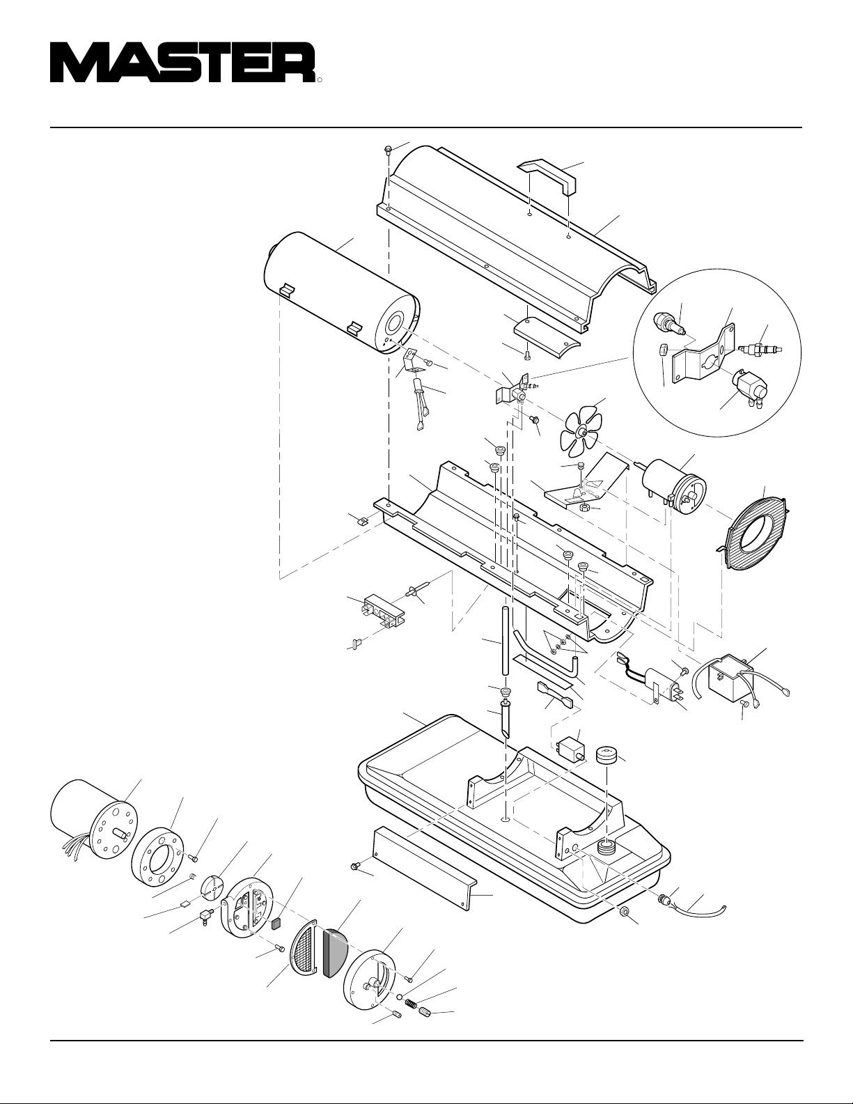
ILLUSTRATED
PARTS
1
BREAKDOWN
35,000 BTU/HR
24
33
41
2
4
11-5
5
6
27
13
13
11
17
22
22
39
16
21
43
21
20
15
11-4
25
7
23
8
9
34
11-1
11-2
11-3
18
19
31
18-1
18-2
18-3
18-17
18-16
Motor and Pump Assembly
18-18
18-15
18-4
18-14
18-5
18-6
18-7
18-13
22
37
18-8
14
18-9
18-10
29
30
18-11
18-12
38
28
35
26
42
36
40
14
12
32
10
104468
Page 15

OWNER’S MANUAL
PARTS LIST
35,000 BTU/HR
KEY PART PART
NO. NUMBER DESCRIPTION QTY.
1 M51104-01 Handle 1
2 098511-54 Upper Shell 1
3 102432-01 Screw/Lockwasher, 1/2" 6
4 098512-43 Combustion Chamber 1
5 M51108-01 Heat Shield 1
6 M11084-29 Screw, #10-16 x 3/4" 2
7 M16660 Photocell Bracket 1
8 M10908-2 Screw, #6-32 x 3/8" 2
9 HA3019 Photocell Assembly 1
10 079673-06 Power Cord 1
11 ** Burner Strap Assembly 1
11-1 097124-01 Bracket 1
11-2 HA3013 Spark Plug 1
11-3 079980-01 Nozzle Adapter 1
11-4 M29824 Nut, 14mm 1
11-5 HA3006 Nozzle 1
12 102801-01 Power Line RFI Filter 1
13 M30865-02 Bushing 2
14 M50400 Strain Relief Bushing 1
15 M30884 Fan 1
16 M50631 Rubber Bumper 2
17 101205-01 Motor Bracket 1
18 ** Motor and Pump Assembly 1
18-1 098642-02 Motor (230V/50Hz) 1
18-2 079975-03 Pump Body 1
18-3 M22009 Insert 1
18-4 M22456-2 Rotor 1
18-5 M29608 End Pump Cover 1
18-6 M29632 Lint Filter 1
18-7 M29633 Intake Filter 1
18-8 M29609 End Filter Cover 1
18-9 M12461-31 Screw, #10-32 x 1" 3
18-10 M8940 Steel Ball (1/4" Dia.) 1
18-11 M10993-1 Pressure Relief Spring 1
18-12 M27694 Adjusting Screw 1
18-13 M22997 Plug 1
18-14 M29612-01 Output Filter 1
18-15 M12461-32 Screw, #10-32 x 1 1/8" 6
This list contains replaceable parts used in your heater. When ordering parts, be sure to
provide the correct model and serial numbers (from the model plate), then the part number
and description of the desired part.
KEY PART PART
NO. NUMBER DESCRIPTION QTY.
18-16 M50016 Elbow, 90˚ (Barb Fitting) 1
18-17 M8643-2 Blade 4
18-18 FHPF3-6C Screw, #10-32 x 3/4" 2
19 M51105-01 Fan Guard 1
20 NTC-4C Hex locknut 2
21 M50104-02 Bushing (wires) 2
22 102431-01 Screw/Lockwasher, 1/2" 10
23 098511-12 Lower Shell 1
24 M11271-8 Clip Nut 6
25 RF3-6B Screw, #10-32 x 3/4" 1
26 M29652-04 Rubber Airline 1
27 M29652-05 Fuel Line 1
28 M16841-57 Wire Assembly (red 8 1/2") 1
29 M10990-3 Rubber Bushing 1
30 M50876-04 Fuel Filter Assembly 1
(Includes bushing)
31 102482-02 Electronic Ignitor 1
32 M11084-29 Screw, #10-16 x 3/4" 2
33 099125-02 Terminal Board 1
34 099157-01 Rivet 1
35 097630-02 Flame-Out Control 1
36 097702-01 Fuel Tank Cap 1
37 098513-73 Fuel Tank 1
38 M50899-03AA Side Cover 1
39 NPF-3B Nut, #10-32 3
40 099177-01 Hex Nut 1
41 078918-01 Terminal Board Tab Cap 1
42 097785-01 Vinyl Foam Gasket 1
43 WLE-3 Lock Washer, #10 2
PARTS AVAILABLE - NOT SHOWN
HA2210 Filler Neck Screen 1
097649-01 Tradename Decal 2
M9900-192 Combustion Chamber
Ground Wire 1
102944-01 Decal Package 1
**Not available as an assembly, order parts separately.
104468
15
Page 16

R
PORTABLE FORCED AIR HEATERS
3
ILLUSTRATED
PARTS
1
BREAKDOWN
70,000 BTU/HR
Burner Head Assembly
10-1
10-2
10-4
10-3
10-6
18-1
18-2
18-18
18-3
18-17
18-16
Motor and Pump Assembly
18-4
18-15
18-14
10-5
10-7
18-5
18-6
4
24
35
43
40
18-7
18-13
11
39
6
18-8
23
36
16
8
18-9
18-10
7
18-11
18-12
12
12
31
32
29
10
2
5
14
11
25
17
30
41
21
15
38
16
45
28
44
26
20
21
11
22
37
42
18
19
27
33
34
13
9
104468
Page 17

OWNER’S MANUAL
PARTS LIST
70,000 BTU/HR
KEY PART PART
NO. NUMBER DESCRIPTION QTY.
1 M51104-01 Handle 1
2 098511-54 Upper Shell 1
3 102432-01 Screw/Lockwasher, 1/2" 6
4 098512-44 Combustion Chamber 1
5 M11084-29 Screw, #10-16 x 3/4" 2
6 M16660 Photocell Bracket 1
7 M10908-2 Screw, #6-32 x 3/8" 2
8 HA3019 Photocell Assembly 1
9 079673-06 Power Cord 1
10 ** Burner Head Assembly 1
10-1 HA3008 Nozzle 1
10-2 M10659-1 Nozzle Seal Washer 2
10-3 M10809-1 Nozzle Seal Spring 1
10-4 M8882 Nozzle Seal Sleeve 1
10-5 M51098-02 Burner Head Body 1
10-6 M50820-01 Barb Fitting 2
10-7 HA3012 Spark Plug 1
11 102431-01 Screw/Lockwasher, 1/2" 11
12 M30865-02 Bushing 2
13 M50400 Strain Relief Bushing 1
14 M30884 Fan 1
15 M50631 Rubber Bumper 2
16 M12461-13 Screw, #8-32 x 1/4" 2
(holds relay in position)
17 101205-01 Motor/Relay Bracket 1
18 ** Motor and Pump Assembly 1
18-1 102001-16 Motor (230V/50Hz) 1
18-2 079975-02 Pump Body 1
18-3 M22009 Insert 1
18-4 M22456-1 Rotor 1
18-5 M29608 End Pump Cover 1
18-6 M29632 Lint Filter 1
18-7 M29633 Intake Filter 1
18-8 M29609 End Filter Cover 1
18-9 M12461-31 Screw, #10-32 x 1" 3
18-10 M8940 Steel Ball (1/4" Dia.) 1
18-11 M10993-1 Pressure Relief Spring 1
18-12 M27694 Adjusting Screw 1
18-13 M22997 Plug 1
18-14 M29612-01 Output Filter 1
This list contains replaceable parts used in your heater. When ordering parts, be sure to
provide the correct model and serial numbers (from the model plate), then the part number
and description of the desired part.
KEY PART PART
NO. NUMBER DESCRIPTION QTY.
18-15 M12461-31 Screw, #10-32 x 1" 6
18-16 M50016 Elbow, 90˚ (Barb Fitting) 1
18-17 M8643 Blade 4
18-18 FHPF3-5C Screw, #10-32 x 5/8" 2
19 M51105-01 Fan Guard 1
20 NTC-4C Hex locknut 2
21 M50104-02 Bushing (wires) 2
22 102801-01 Power Line RFI Filter 1
23 098511-12 Lower Shell 1
24 M11271-8 Clip Nut 6
25 098136-05 Relay (motor start) 1
26 M16841-58 Wire Assembly (red 9 1/2") 1
27 RF3-6B Screw, #10-32 x 3/4" 1
28 M29652-04 Rubber Airline 1
29 079973-01 Fuel Line 1
30 M16841-57 Wire Assembly (red 8 1/2") 1
31 M10990-3 Rubber Bushing 1
32 M50876-05 Fuel Filter Assembly 1
(Includes bushing)
33 102482-02 Electronic Ignitor 1
34 M11084-29 Screw, #10-16 x 3/4" 2
35 099125-02 Terminal Board 1
36 099157-01 Rivet 1
37 097702-01 Fuel Tank Cap 1
38 097630-02 Flame-Out Control 1
39 098513-74 Fuel Tank 1
40 M50899-03AA Side Cover 1
41 NPF-3B Nut, #10-32 3
42 099177-01 Hex Nut 1
43 078918-01 Terminal Board Tab Cap 1
44 097785-01 Vinyl Foam Gasket 1
45 WLE-3 Lock Washer, #10 2
PARTS AVAILABLE - NOT SHOWN
HA2210 Filler Neck Screen 1
097649-01 Tradename Decal 2
M9900-192 Combustion Chamber
Ground Wire 1
102944-02 Decal Package 1
**Not available as an assembly, order parts separately.
104468
17
Page 18

R
PORTABLE FORCED AIR HEATERS
ILLUSTRATED
PARTS
BREAKDOWN
100,000 BTU/HR
8-1
8-2
8-4
8-3
8-5
8-7
2
1
3
4
5
31
30
8
7
9
15
10
26
11
25
17
28
20
12
13
14
21
8-6
Burner Head Assembly
13-1
13-2
13-18
13-17
13-16
13-15
Motor and Pump Assembly
13-3
13-4
13-5
13-14
13-6
13-13
42
27
23
24
36
44
16
9
13-7
13-8
13-9
13-12
37
13-10
13-11
35
33
34
18
19
38
39
6
9
43
40
22
32
29
41
18
104468
Page 19

OWNER’S MANUAL
PARTS LIST
100,000 BTU/HR
KEY PART PART
NO. NUMBER DESCRIPTION QTY.
1 098511-138 Upper Shell 1
2 102432-01 Screw/Lockwasher, 1/2" 8
3 098512-31 Combustion Chamber 1
4 M16660 Photocell Bracket 1
5 HA3019 Photocell Assembly 1
6 M27417 Drain Plug 1
7 M10908-2 Screw, #6-32 x 3/8" 2
8 ** Burner Head Assembly 1
8-1 100735-15 Nozzle 1
8-2 M10659-1 Nozzle Seal Washer 2
8-3 M10809-1 Nozzle Seal Spring 1
8-4 M8882 Nozzle Seal Sleeve 1
8-5 M50924-03 Burner Head Body 1
8-6 M50820-02 Barb Fitting 2
8-7 HA3012 Spark Plug 1
9 102431-01 Screw/Lockwasher, 1/2" 13
10 M50814-06 Air Line 1
11 M51345-01 Fuel Line 1
12 102042-01 Fan 1
13 ** Motor and Pump Assembly 1
13-1 102001-03 Motor with capacitor
(230V/50Hz) 1
13-2 079975-02 Pump Body 1
13-3 FHPF3-5C Screw, #10-32 x 5/8" 2
13-4 M22009 Insert 1
13-5 M22456-1 Rotor 1
13-6 M50545 End Pump Cover 1
13-7 M12179 Intake Filter 1
13-8 M16545 End Filter Cover 1
13-9 M8940 Steel Ball (1/4" Dia.) 1
13-10 M10993-1 Pressure Relief Spring 1
13-11 M27694 Adjusting Screw 1
13-12 M22997 Plug 1
13-13 M12461-31 Screw, #10-32 x 1" 4
13-14 M12244-1 Output Filter 1
13-15 M12461-31 Screw, #10-32 x 1" 6
13-16 M11637 Lint Filter 1
13-17 M50820-02 Barb Fitting 1
13-18 M8643 Blade 4
14 M51114-01 Fan Guard 1
This list contains replaceable parts used in your heater. When ordering parts, be sure to
provide the correct model and serial numbers (from the model plate), then the part number
and description of the desired part.
KEY PART PART
NO. NUMBER DESCRIPTION QTY.
15 M50631 Rubber Bumper 2
16 097468-01 Edge Liner 1
17 101206-01 Motor and Relay
Bracket Assembly 1
18 WLE-3 Lock Washer, #10 2
19 NPF-3B Nut, #10-32 3
20 NTC-4C Hex locknut 2
21 102482-02 Electronic Ignitor 1
22 M11084-29 Screw, #10-16 x 3/4" 2
23 099125-02 Terminal Board 1
24 099157-01 Rivet 1
25 M50104-03 Bushing 1
26 M50104-03 Bushing 1
27 M50104-01 Bushing 2
28 099213-01 Button Plug 1
29 102801-01 Power Line RFI Filter 1
30 098511-191 Lower Shell 1
31 M11271-8 Clip Nut 8
32 RF3-6B Screw, #10-32 x 3/4" 1
33 M51150-01 Fuel filter 1
34 M10990-3 Rubber Bushing 1
35 M51151-01 Fuel Line 1
36 098513-75 Fuel Tank 1
37 097702-01 Fuel Tank Cap 1
38 M16841-57 Wire Assembly (red 8 1/2") 1
39 097630-02 Flame-Out Control 1
40 M50400 Strain Relief Bushing 1
41 079673-06 Power Cord 1
42 M51077-01AA Side Cover 1
43 099177-01 Hex Nut 1
44 078918-01 Terminal Board Tab Cap 1
PARTS AVAILABLE - NOT SHOWN
HA2210 Filler Neck Screen 1
097650-01 Tradename Decal 2
M9900-192 Combustion Chamber
Ground Wire 1
102944-03 Decal Package 1
**Not available as an assembly, order parts separately.
104468
19
Page 20

R
PORTABLE FORCED AIR HEATERS
ILLUSTRATED
PARTS
BREAKDOWN
150,000 BTU/HR
8-1
8-2
8-4
8-3
8-5
8-7
2
1
3
4
5
31
30
8
7
9
15
10
26
25
11
17
46
28
12
20
13
14
21
8-6
Burner Head Assembly
13-1
13-2
13-18
13-17
13-16
13-15
Motor and Pump Assembly
13-3
13-14
13-4
13-5
13-6
13-13
42
16
23
43
13-7
44
13-8
13-12
20
24
36
13-9
37
13-10
13-11
35
33
34
38
19
27
9
18
39
45
40
6
22
32
29
41
104468
Page 21

OWNER’S MANUAL
PARTS LIST
150,000 BTU/HR
KEY PART PART
NO. NUMBER DESCRIPTION QTY.
1 098511-138 Upper Shell 1
2 102432-01 Screw/Lockwasher, 1/2" 8
3 098512-36 Combustion Chamber 1
4 099229-01 Photocell Bracket 1
5 HA3019 Photocell Assembly 1
6 M27417 Drain Plug 1
7 M10908-2 Screw, #6-32 x 3/8" 2
8 ** Burner Head Assembly 1
8-1 100735-11 Nozzle 1
8-2 M10659-1 Nozzle Seal Washer 2
8-3 M10809-1 Nozzle Seal Spring 1
8-4 M8882 Nozzle Seal Sleeve 1
8-5 M50924-08 Burner Head Body 1
8-6 M50820-02 Barb Fitting 2
8-7 HA3012 Spark Plug 1
9 102431-01 Screw/Lockwasher, 1/2" 9
10 M50814-06 Air Line 1
11 M51345-01 Fuel Line 1
12 102042-01 Fan 1
13 ** Motor and Pump Assembly 1
13-1 102001-03 Motor (with capacitor) 1
13-2 079975-03 Pump Body 1
13-3 FHPF3-6C Screw, #10-32 x 3/4" 2
13-4 M22009 Insert 1
13-5 M22456-2 Rotor 1
13-6 M50545 End Pump Cover 1
13-7 M12179 Intake Filter 1
13-8 M16545 End Filter Cover 1
13-9 M8940 Steel Ball (1/4" Dia.) 1
13-10 M10993-1 Pressure Relief Spring 1
13-11 M27694 Adjusting Screw 1
13-12 M22997 Plug 1
13-13 M12461-31 Screw, #10-32 x 1" 4
13-14 M12244-1 Output Filter 1
13-15 M12461-32 Screw, #10-32 x 1 1/8" 6
13-16 M11637 Lint Filter 1
13-17 M50820-02 Barb Fitting 1
13-18 M8643-2 Blade 4
14 M51114-01 Fan Guard 1
15 M50631 Rubber Bumper 2
This list contains replaceable parts used in your heater. When ordering parts, be sure to
provide the correct model and serial numbers (from the model plate), then the part number
and description of the desired part.
KEY PART PART
NO. NUMBER DESCRIPTION QTY.
16 097468-01 Edge Liner 1
17 101206-01 Motor Bracket 1
18 WLE-3 Lock Washer, #10 2
19 NPF-3B Nut, #10-32 3
20 NTC-4C Hex locknut 2
21 102482-02 Electronic Ignitor 1
22 M11084-29 Screw, #10-16 x 3/4" 2
23 099125-02 Terminal Board 1
24 099157-01 Rivet 1
25 M50104-03 Bushing 1
26 M50104-03 Bushing 1
27 M50104-01 Bushing 2
28 099213-01 Button Plug 1
29 102801-01 Power Line RFI Filter 1
30 098511-191 Lower Shell 1
31 M11271-8 Clip Nut 8
32 RF3-6B Screw, #10-32 x 3/4" 1
33 M51150-01 Fuel filter 1
34 M10990-3 Rubber Bushing 1
35 M51151-02 Fuel Line 1
36 098513-76 Fuel Tank 1
37 097702-01 Fuel Tank Cap 1
38 M16841-57 Wire Assembly (red 8 1/2") 1
39 097630-02 Flame-Out Control 1
40 M50400 Strain Relief Bushing 1
41 079673-06 Power Cord 1
42 M51077-01AA Side Cover 1
43 M11084-27 Screw, #10-16 x 1/2" 4
44 078918-01 Terminal Board Tab Cap 1
45 099177-01 Hex Nut 1
46 097785-04 Vinyl Foam Gasket 2
PARTS AVAILABLE - NOT SHOWN
HA2210 Filler Neck Screen 1
097650-01 Tradename Decal 2
M9900-192 Combustion Chamber
Ground Wire 1
102944-04 Decal Package 1
**Not available as an assembly, order parts separately.
104468
21
Page 22
R
PORTABLE FORCED AIR HEATERS
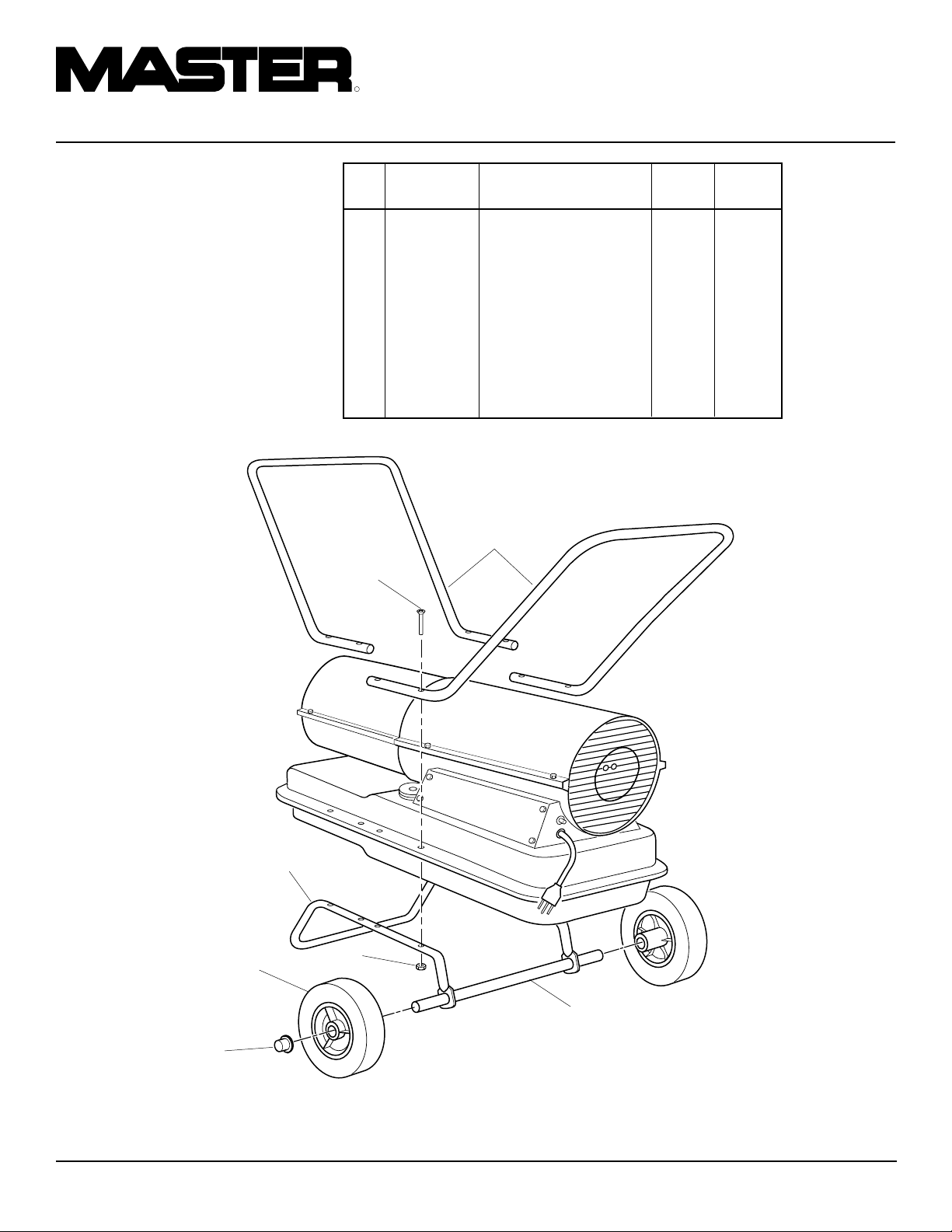
WHEELS AND
HANDLES
100,000 AND 150,000 BTU/HR
MODELS
KEY PART PART 100,000 150,000
NO. NUMBER DESCRIPTION QTY. QTY.
1 HA2203 Handles 2 —
HA2204 Handles — 2
2 M12345-33 Screw, #10-24 x 1 3/4" 8 8
3 M12342-3 Wheel Support Frame 1 —
M12831-3 Wheel Support Frame — 1
4 NTC-3C Hex Nut, #10-24 8 8
5 097896-03 Wheel 2 2
6 M28526 Cap Nut 2 2
7 M51015-01 Axle 1 —
M16801-2 Axle — 1
1
2
3
5
6
4
7
22
104468
Page 23

ACCESSORIES
Purchase accessories from your local dealer.
AIR GAUGE KIT - HA1180
For all models. Special tool to check pump
pressure.
OWNER’S MANUAL
STANDARD WHEELS AND
HANDLE KIT - HA1206
Makes heater even more portable and convenient. Easy to assemble.
For 35/70,000 Btu/Hr models.
HEAVY DUTY WHEELS AND
HANDLE KIT - HA1202
For heavy duty applications. Makes your heater
even more portable and convenient.
For 35/70,000 Btu/Hr models.
104468
23
Page 24

WARRANTY AND REPAIR SERVICE
CERTIFICATE OF GENERAL
EQUIPMENT - LIMITED 90 DAY WARRANTY
DESA International warrants new Products sold by it to be
free from defects in material or workmanship for a period of
ninety days after date of delivery to the first user and subject to
the following conditions:
DESA International's obligation and liability under this
Warranty is expressly limited to repairing or replacing at DESA
International's option, any parts which appear to DESA International upon inspection to have been defective in material or
workmanship when shipped from the factory. Such parts shall
be provided at no cost to the user, at the business establishment
of any factory authorized service center or the factory during
regular working hours. The Warranty shall not apply to component parts or accessories of Products not manufactured by
DESA International and which carry the warranty of the manufacturer thereof, or to normal maintenance (such as pressure
adjustments) or to normal maintenance parts (such as filters
and spark plugs). Replacement or repair parts installed in the
Product covered by this Warranty are warranted only for the
remainder of this Warranty as if such parts were original components of said Product. DESA INTERNATIONAL MAKES NO
OTHER EXPRESS WARRANTY. TO THE EXTENT PERMITTED BY LAW DESA INTERNATIONAL MAKES NO IMPLIED
WARRANTY AND MAKES NO WARRANTY OF MERCHANTABILITY OR FITNESS FOR ANY PARTICULAR PUR-
POSE. IN ANY EVENT IMPLIED WARRANTIES INCLUDING
THOSE OF MERCHANTABILITY AND FITNESS FOR A PARTICULAR PURPOSE ARE LIMITED TO THE DURATION OF
THIS EXPRESS WARRANTY.
Any transportation charges, costs of installation, duty,
taxes or any other charges whatsoever must be borne by the
user. DESA International's obligation under this limited Warranty shall not include any liability for direct, indirect, incidental,
or consequential damage or delay. If requested by DESA
International, Products or parts for which a warranty claim is
made are to be returned transportation prepaid by user to the
factory. Any improper use, including operation after discovery
of defective or worn parts, operation beyond capacity, substitution of parts not approved by DESA International, or any
alteration or repair by others in such manner as in DESA
International's judgement affects the Product materially and
adversely, shall void this Warranty.
NO EMPLOYEE OR REPRESENTATIVE IS AUTHORIZED
TO CHANGE THIS WARRANTY IN ANY WAY OR GRANT
ANY OTHER WARRANTY UNLESS SUCH CHANGE IS
MADE IN WRITING AND SIGNED BY AN OFFICER OF DESA
INTERNATIONAL AT ITS HOME OFFICE.
WARRANTY SERVICE
Always specify model and serial numbers when communicating
with the factory.
We reserve the right to amend these specifications at any time
without notice. The only Warranty applicable is our standard
written Warranty. We make no other Warranty, expressed or
implied.
A Service Manual is available by writing to the Technical Service
Department at:
Corporate Headquarters
2701 Industrial Drive
P.O. Box 90004
Bowling Green, Kentucky 42102-9004
U.S.A.
Printed in U.S.A.
Page 25

R
CALENTADORES
PORTATILES DE AIRE
FORZADO
MANUAL DEL PROPIETARIO
Tamaños: 10,2 (35.000) 20,5 (70.000) 29,3 (100.000) 44 kW (150.000 Btu/hr)
Modelos: B35CEA, B70CEA, B100CEA, Y B150CEA
IMPORTANTE: Lea y comprenda este manual antes de armar, encender o dar servicio
al calentador. El uso indebido del calentador puede causar lesiones graves. Guarde
este manual para referencia futura.
104468 01
NOT A UPC
104468-01
Rev. A
12/97
Page 26
R
CALENTADORES PORTATILES DE AIRE FORZADO
INFORMACION DE
SEGURIDAD
ADVERTENCIAS
IMPORTANTE: Lea este manual
del propietario detenida y completamente antes de intentar armar, usar o dar servicio al calentador. El uso indebido de este
calentador puede causar lesiones graves o la muerte a causa
de las quemaduras, incendios,
explosiones, choques eléctricos
y envenenamiento por monóxido
de carbono.
PELIGRO: El envenenamiento por monóxido de carbono puede causar la muerte.
Envenenamiento por monóxido de
carbono: Los primeros síntomas del enve-
nenamiento por monóxido de carbono son
parecidos a los de la gripe e incluyen dolores
de cabeza, mareos o náuseas. Si se experimentan estos síntomas, el calentador podría
estar funcionando mal. ¡Busque aire fresco
de inmediato! Solicite la reparación del
calentador. Algunos individuos se ven más
afectados por el monóxido de carbono que
otros. Estos incluyen las mujeres embarazadas, individuos con padecimientos del corazón o los pulmones o con anemia, individuos bajo los efectos del alcohol e individuos a grandes alturas.
Asegúrese de leer y comprender todas las
advertencias. Guarde este manual para referencia. Es su guía para el uso seguro y
adecuado de este calentador.
• Para evitar el riesgo de incendio o explosión, use sólo keroseno o fueloil No.
1. Nunca use gasolina, nafta, diluyentes
de pintura, alcohol u otros combustibles muy inflamables.
• Abastecimiento de combustible
a) El personal involucrado en el abas-
tecimiento del combustible deberá
ser calificado y estar plenamente familiarizado con las instrucciones del
fabricante y los reglamentos aplicables en cuanto al abastecimiento seguro de combustible de las unidades
de calefacción.
b)Sólo se debe utilizar el tipo de com-
bustible especificado en la chapa de
datos del calentador.
c) Se deberá extinguir toda llama, in-
cluyendo la luz piloto en su caso, y
permitir que el calentador se enfríe
antes de abastecerlo de combustible.
d)Durante el abastecimiento de com-
bustible, todas las líneas y conexiones de combustible deberán
inspeccionarse en busca de fugas.
Todas las fugas deberán repararse
antes de volver a poner en servicio
el calentador.
e) En ningún momento se deberá alma-
cenar una cantidad de combustible
mayor que la necesaria para un día
de funcionamiento en el interior de
un edificio en las cercanías del calentador. El depósito de abasto de
combustible deberá estar ubicado
fuera de la estructura.
f) Todo el combustible almacenado
deberá ubicarse a un mínimo de 762
cm (25 pies) de los calentadores,
sopletes, equipo de soldadura y otras
fuentes similares de inflamación (excepción: el tanque de combustible
incorporado en el calentador).
g)Siempre que sea posible, el almace-
namiento de combustible deberá confinarse a zonas donde las aberturas
en el suelo no permitan que el combustible gotee sobre una llama o sea
inflamado por una llama ubicada a
una altura más baja.
h)El almacenamiento del combustible
deberá efectuarse según las disposiciones de las autoridades competentes.
• Nunca use el calentador en presencia de
vapores de gasolina, de diluyente de pintura u otros vapores muy inflamables.
• Respete todos los reglamentos y códigos locales al usar el calentador.
• Los calentadores utilizados en las cercanías de alquitranado, lonas o materiales
de envoltura similares deberán ubicarse
a una distancia segura de tales materiales. La distancia mínima recomendada es
304,8 cm (10 pies). Además, se recomienda que tales materiales tengan propiedades retardantes a las llamas. Estos materiales de envoltura deberán fijarse de
modo seguro para impedir su combustión o que volteen el calentador debido a
la acción del viento.
• Utilícelo solamente en lugares con buena ventilación. Deje una abertura de por
lo menos 2800 cm2 (3 ft2) para la entrada de aire fresco exterior por cada 29,3
kW (100.000 Btu/hr) de capacidad.
• Utilícelo solamente en lugares exentos
de vapores inflamables o contenido elevado de polvo.
• Use solamente el voltaje eléctrico y la
frecuencia especificados en la chapa del
número de modelo.
• Use solamente un cordón de extensión
de tres clavijas con puesta a tierra.
• Los espacios mínimos entre el calentador y materiales combustibles son:
Salida: 250 cm (8 ft)
Lados, partes superior y trasera: 125 cm
(4 ft)
• Coloque el calentador en una superficie estable y nivelada mientras el calentador está caliente o funcionando, de
lo contrario podría ocurrir un incendio.
•
Para trasladar o guardar el calentador, manténgalo en posición nivelada, de lo contrario podría derramarse el combustible.
• Deje el calentador fuera del alcance de
los niños y animales.
• Desenchufe el calentador cuando no
esté en uso.
• Cuando se usa con termostato, el calentador puede arrancar en cualquier
momento.
• Nunca use el calentador en habitaciones o dormitorios.
• Nunca bloquee la entrada de aire (trasera) ni la salida de aire (delantera) del
calentador.
• Nunca mueva, manipule, reabastezca
de combustible ni dé servicio a un calentador caliente, en funcionamiento o
enchufado.
• Nunca conecte ductos a la parte delantera o trasera del calentador. El uso de
ductos podría reducir el flujo de aire
que el calentador necesita. El calentador entonces produciría monóxido de
carbono en exceso.
2
104468
Page 27

MANUAL DEL PROPIETARIO
IDENTIFICACION
DEL PRODUCTO
Salida de aire
caliente
Casco
superior
Casco inferior
Tanque de
combustible
Cubierta lateral
Botón de reposición
del control de
extinción de llamas
Figura 1 - Modelos de 10,2/20,5 kW (35.000/70.000 Btu/hr)
Salida
de aire
caliente
Asa
Casco superior
Protector del
ventilador
Cubierta del
extremo del filtro
de aire
Tapa de
combustible
Cordón
eléctrico
DESEMBALAJE
1. Quite todo el material de embalar aplicado al calentador para el transporte.
2. Saque todos los componentes de la caja.
3. Inspeccione los componentes en busca
de daños ocurridos durante el transporte. Si el calentador ha sufrido daños,
informe oportunamente al concesionario donde se compró el calentador.
Casco
inferior
Tapa de
combustible
Cubierta
lateral
Botón de reposición
del control de
extinción de llamas
Figura 2 - Modelos de 29,3/44 kW (100.000/150.000 Btu/hr)
Protector del
ventilador
Tanque de
combustible
Cordón
eléctrico
104468
3
Page 28

R
CALENTADORES PORTATILES DE AIRE FORZADO
ARMADO
(SÓLO PARA MODELOS DE
29,3 Y 44 KW [100.000 Y
150.000 BTU/HR])
Estos modelos se proveen con ruedas y asas.
Las ruedas, asas y la tornillería de montaje
se encuentran en la caja de embalaje.
Herramientas necesarias
• Destornillador Phillips mediano
• Llave ajustable o de boca de 3/8"
• Martillo
1. Deslice el eje a través del bastidor de
soporte de las ruedas. Instale las ruedas en el eje.
IMPORTANTE:
oriente el cubo extendido de las ruedas
hacia el bastidor de soporte de las ruedas (vea la Figura 3).
Al instalar las ruedas,
2. Coloque las tuercas ciegas en los extremos del eje. Martíllelas suavemente
para fijarlas.
3. Coloque el calentador sobre el bastidor de soporte de las ruedas. Asegúrese que el extremo de entrada de aire
(posterior) del calentador esté sobre las
ruedas. Alinee los agujeros de la pestaña del tanque de combustible con los
agujeros del bastidor de soporte de las
ruedas.
4. Coloque el asa delantera y el asa trasera encima de la pestaña del tanque de
combustible. Inserte los tornillos a través de las asas, de la pestaña del tanque de combustible y del bastidor de
soporte de las ruedas. Ponga una tuerca apretada a mano en cada tornillo
después de insertarlo.
5. Después de insertar todos los tornillos,
apriete las tuercas firmemente.
Asa delantera
COMBUSTIBLES
ADVERTENCIA: Para evitar el
riesgo de incendio o explosión, use
sólo keroseno o fueloil No. 1. Nunca use gasolina, nafta, diluyentes
de pintura, alcohol u otros combustibles muy inflamables.
No use combustibles pesados como el fueloil
No. 2 ó diesel No. 2. El uso de estos combustibles causará:
• taponamiento del filtro de combustible
y de la boquilla
• depósitos de carbón en la bujía
• necesidad de usar aditivo anticongelador
no tóxico en el combustible durante el
tiempo muy frío
IMPORTANTE:
macenar KEROSENO SOLAMENTE.
Asegúrese que el envase esté bien limpio.
Las materias extrañas tales como óxido, tierra o agua harán que el control de extinción de
llamas apague el calentador. Las materias
extrañas también harán necesaria la limpieza
frecuente del sistema de combustible.
Utilice un envase para al-
Salida de
aire caliente
Pestaña del
tanque de
combustible
Bastidor de
soporte de
las ruedas
Rueda
Tuerca
ciega
Figura 3 - Conjunto de ruedas y asas, sólo modelos de 29,3/44 kW
(100.000/150.000 Btu/hr)
Tornillo
Tuerca
Eje
Cubo
extendido
4
Asa trasera
Entrada
de aire
VENTILACION
ADVERTENCIA: Observe los
requisitos mínimos de ventilación
de aire fresco exterior. Si no se
provee la ventilación debida con
aire fresco exterior, podría ocurrir
el envenenamiento por monóxido
de carbono. Antes de hacer funcionar el calentador, asegúrese de
proporcionar buena ventilación
con aire fresco exterior.
Deje una abertura de por lo menos 2800 cm
(3 ft2) por cada 29,3 kW (100.000 Btu/hr) de
capacidad para la entrada de aire. Proporcione aire fresco adicional si se usan más
calentadores.
Ejemplo:
Btu/hr) requiere una de las siguientes aberturas:
• puerta de garaje para dos carros de 4,88
• puerta de garaje para un carro de 2,75 m
• dos ventanas de 76,20 cm (30 in.) de ancho
Un calentador de 44 kW (150.000
m (16 ft) de ancho levantada por lo menos 8,59 cm (3,38 in.)
(9 ft) de ancho levantada por lo menos
15,24 cm (6 in.)
levantadas por lo menos 30,48 cm (12 in.)
104468
2
Page 29

MANUAL DEL PROPIETARIO
TEORIA DE
FUNCIONAMIENTO
Sistema de combustible: La bomba de
aire fuerza el paso del aire por la línea de
aire. De allí, el aire es empujado a través de
la boquilla del quemador. Este aire hace que
el combustible del tanque suba. Un vapor
fino de combustible es rociado en la cámara
de combustión.
Sistema de aire: El motor hace girar el
ventilador. El ventilador empuja el aire al
interior y alrededor de la cámara de combustión. Este aire se calienta y proporciona un
chorro de aire caliente y limpio.
Sistema de encendido: El ignitor electrónico envía voltaje a la bujía. La bujía
enciende la mezcla de combustible y aire.
Sistema de control de extinción de
llamas: Este sistema apaga el calentador
en caso de extinguirse la llama.
Cámara de
combustión
Salida
de aire
caliente
y limpio
FUNCIONAMIENTO
ADVERTENCIA: Estudie y
comprenda las advertencias dadas en la sección Información de
seguridad. Son necesarias para
el funcionamiento sin peligro de
este calentador. Respete todos
los códigos locales al usar este
calentador.
Para encender el calentador
1. Observe toda la información sobre ventilación y seguridad.
2. Llene el tanque de combustible con
keroseno o fueloil No. 1.
3. Ponga la tapa de combustible.
4. Enchufe el cordón eléctrico del calentador en un tomacorriente estándar de 230
V/50 Hz con puesta a tierra. Utilice un
cordón de extensión si es necesario. Use
solamente un cordón de extensión de tres
clavijas con puesta a tierra.
Bomba de
aire
Bujía
Quemador
Motor
Ventilador
Filtro de
admisión
de aire
Entrada
de aire
frío
Requisitos del calibre del
alambre del cordón de
extensión
Hasta 30,5 m (100 ft) de largo, use conductores de 1,0 mm2 (16 AWG); de 30,6 a 61 m
(101 a 200 ft), use conductores de 1,5 mm
(14 AWG)
El calentador arrancará al enchufar el cordón eléctrico en el tomacorriente. De lo
contrario, oprima el botón de reposición del
control de extinción de llamas (vea las Figuras 5 y 6).
Para apagar el calentador
1. Desenchufe el cordón eléctrico del
tomacorriente.
Para volver a encender el
calentador
1. Espere 2 minutos después de apagar el
calentador.
2. Repita los pasos bajo Para encender el
calentador.
Botón de
reposición del
control de
extinción de
llamas
2
Tanque de
combustible
Figura 4 - Vista en corte transversal del funcionamiento
104468
Boquilla
Aire para el sistema
de combustible
Filtro de
combustible
Aire para combustión
y calefacción
Línea de aire
al quemador
5
Filtro de
aire de
salida
Ignitor
electrónico
Combustible
Figura 5 - Botón de reposición del control
de extinción de llamas, modelos de 10,2/
20,5 kW (35/70.000 Btu/hr)
Botón de
reposición del
control de
extinción de
llamas
Figura 6 - Botón de reposición del control
de extinción de llamas, modelo de 29,3/
44 kW (100.000/150.000 Btu/hr)
Page 30

R
CALENTADORES PORTATILES DE AIRE FORZADO
ALMACENAMIENTO,
TRANSPORTE O
EMBARQUE
Nota:
Si se está despachando la unidad para
embarque, las compañías transportistas exigen que los tanques de combustible estén
vacíos.
1. Vaciar el tanque de combustible.
Nota:
Algunos modelos tienen el tapón
de vaciado en el lado inferior del tanque de combustible. De ser así, sacar
el tapón para vaciar todo el combustible. Si el calentador no tiene tapón de
vaciado, vaciar el combustible por la
abertura de la tapa de combustible.
Asegurarse de haber extraído todo el
combustible.
2. Volver a colocar el tapón de vaciado,
si lo tiene.
3. Si se observa la presencia de basura en
el combustible viejo, añadir 1 ó 2 litros
de keroseno al tanque, agitarlo y volver a vaciarlo. Esto ayuda a impedir que
el exceso de basura tapone los filtros
en el futuro.
4. Volver a colocar la tapa del tanque de
combustible o el tapón de vaciado.
Desechar el combustible viejo de manera adecuada. Consultar a una estación
de servicio local que efectúe el reciclaje
de derivados del petróleo.
5. Si se está almacenando la unidad,
almacenarla en un lugar seco. Asegurarse que el lugar de almacenamiento esté
libre de polvo y vapores corrosivos.
IMPORTANTE:
durante el verano para usarlo en la siguiente
temporada fría. El usar keroseno viejo podría dañar el calentador.
No almacenar el keroseno
PROGRAMA DE
MANTENIMIENTO
PREVENTIVO
Item
Tanque de combustible
Filtros de salida de
aire y de pelusa
Filtro de admisión de
aire
Filtro de combustible
Bujía
Paletas del ventilador
Motor
Intervalo
1
Enjuáguelo cada 150-200 horas de
funcionamiento o según sea necesario.
Cámbielos cada 500 horas de funcionamiento o anualmente.
Lávelo con agua y jabón y séquelo
cada 500 horas de funcionamiento
o según sea necesario.
Límpielo dos veces por temporada
de frío o según sea necesario.
Límpiela y ajuste el espacio entre
electrodos cada 600 horas de funcionamiento o según sea necesario.
Límpielas cada temporada o según
sea necesario.
No requerido/lubricado permanentemente.
ADVERTENCIA: Nunca repare el
calentador mientras está enchufado, en funcionamiento o caliente.
Podrían ocurrir graves quemaduras
y electrochoque.
Procedimiento
Vea Almacenamiento,
Transporte o Embarque,
más arriba.
Vea Filtros de salida de aire,
de admisión de aire y de
pelusa, página 10.
Vea Filtros de salida de aire,
de admisión de aire y de
pelusa, página 10.
Vea Filtro de combustible,
página 8.
Vea Bujía, página 9.
Vea Ventilador, página 13.
6
104468
Page 31

MANUAL DEL PROPIETARIO
LOCALIZACION DE
AVERIAS
AVERIA OBSERVADA
El calentador se enciende, pero el control de
extinción de llamas lo apaga después de un
rato corto.
El calentador no enciende, pero el motor
funciona por un rato corto.
ADVERTENCIA: Nunca repare el calentador mientras está enchufado,
en funcionamiento o caliente. Podrían ocurrir graves quemaduras y
electrochoque.
CAUSA POSIBLE
1. Presión incorrecta de la bomba
2. Filtros de salida de aire, de admisión de
aire y de pelusa sucios
3. Filtro de combustible sucio
4. Tierra en la boquilla
5. Cristal de la fotocélula sucio
6. Control de extinción de llamas defectuoso
1. Presión incorrecta de la bomba
2. Depósitos de carbón en la bujía y/o espacio entre electrodos inapropiado
3. Filtro de combustible sucio
4. Tierra en la boquilla
5. Agua en el tanque de combustible
SOLUCION
1. Vea Ajuste de la presión de la bomba,
página 10.
2. Vea Filtros de salida de aire, de admi-
sión de aire y de pelusa, página 10.
3. Vea Filtro de combustible, página 8.
4. Vea Boquilla, página 11.
5. Limpie el cristal de la fotocélula.
6. Sustituya el control de extinción de llamas.
1. Vea Ajuste de la presión de la bomba,
página 10.
2. Vea Bujía, página 9.
3. Vea Filtro de combustible, página 8.
4. Vea Boquilla, página 11.
5. Vacíe y enjuague el tanque de combustible con keroseno limpio. Vea Almace-
namiento, Transporte o Embarque, página 6.
El motor no arranca al enchufar el calentador, el ventilador gira lentamente o no gira.
ADVERTENCIA: ¡Alto voltaje!
6. Ignitor electrónico no conectado a tierra
7. Ignitor electrónico defectuoso
1. El control de extinción de llamas no está
reposicionado
2. Rotor de la bomba atascado
6. Asegúrese que el montaje del ignitor
electrónico esté firmemente apretado.
7. Sustituya el ignitor electrónico.
1. Oprima el botón del control de extinción
de llamas, vea las Figuras 5 y 6 en las
página 5.
2. Si el ventilador gira con dificultad, vea
Rotor de la bomba, página 12.
104468
7
Page 32

R
CALENTADORES PORTATILES DE AIRE FORZADO
PROCEDIMIENTOS
DE SERVICIO
ADVERTENCIA: Nunca repare el calentador mientras está
enchufado, en funcionamiento o
caliente. Podrían ocurrir graves
quemaduras y electrochoque.
Remoción del casco superior
1. Quite los tornillos a lo largo de cada lado
del calentador con una llave de tuercas
de 5/16". Estos tornillos sujetan juntos
los cascos superior e inferior.
2. Levante y quite el casco superior.
3. Quite el protector del ventilador.
Filtro de combustible
(Modelos de 10,2/20,5 kW [35.000/
70.000 Btu/hr])
1. Quite los tornillos de la cubierta lateral
con una llave de tuercas de 5/16".
2. Quite la cubierta lateral.
3. Quite la línea de combustible de caucho
del cuello del filtro de combustible.
4. Palanquee cuidadosamente el buje y el
filtro de combustible para sacarlos del
tanque de combustible.
5. Lave el filtro de combustible con combustible limpio y vuelva a colocarlo en
el tanque.
6. Sujete la línea de combustible de caucho al cuello del filtro de combustible.
7. Vuelva a colocar la cubierta lateral.
Filtro de combustible
(Modelo de 29,3/44 kW [100.000/
150.000 Btu/hr])
1. Quite los tornillos de la cubierta lateral
con una llave de tuercas de 5/16".
2. Quite la cubierta lateral.
3. Quite la línea de combustible superior
del cuello del filtro de combustible.
4. Palanquee cuidadosamente el buje, la
línea de combustible inferior y el filtro
de combustible para sacarlos del tanque de combustible.
5. Lave el filtro de combustible con combustible limpio y vuelva a colocarlo en
el tanque.
6. Sujete la línea de combustible superior
al cuello del filtro de combustible.
7. Vuelva a colocar la cubierta lateral.
Casco
superior
Casco
superior
Protector
del
ventilador
Protector del
ventilador
Figura 7 - Remoción del casco superior,
modelos de 10,2/20,5 kW (35.000/70.000
Btu/hr)
Filtro de
combustible
Cubierta
lateral
Figura 9 - Remoción del filtro de combustible, modelos de 10,2/20,5 kW (35.000/70.000 Btu/hr)
Filtro de combustible, buje
y línea de combustible
inferior
Cubierta lateral
Figura 10 - Remoción del filtro de combustible, modelo de 29,3/44 kW (100.000/150.000 Btu/hr)
Figura 8 - Remoción del casco superior,
modelo de 29,3/44 kW (100.000/150.000
Btu/hr)
Línea de
combustible
Línea de
combustible
superior
8
104468
Page 33

MANUAL DEL PROPIETARIO
PROCEDIMIENTOS
DE SERVICIO
Continuación
Bujía
(Modelo de 10,2 kW [35,000 Btu/hr])
1. Quite el casco superior (vea la página 8).
2. Quite el ventilador (vea la página 13).
3. Quite las mangueras de las líneas de
aire y de combustible del conjunto de
la boquilla.
4. Quite el cable de la bujía.
5. Quite los dos tornillos con una llave de
tuercas de 5/16" y quite la banda
fijadora del quemador.
6. Coloque el cuerpo hexagonal de la bujía en una prensa y apriétela.
7. Quite la tuerca de montaje de la bujía
con una llave de boca de 11/16".
8. Quite la banda fijadora del quemador
de la bujía.
9. Limpie la bujía y ajuste el espacio entre electrodos a 1,4 mm (0.055 in.).
10. Vuelva a colocar la banda fijadora del
quemador en la bujía. Gire la banda
fijadora del quemador para posicionar los
electrodos de la bujía (vea la Figura 13).
11. Apriete la bujía con la tuerca de montaje.
12. Suelte el cuerpo hexagonal de la bujía
de la prensa.
13. Vuelva a colocar la banda fijadora del
quemador en la cámara de combustión.
14. Conecte el cable de la bujía.
15. Sujete las mangueras de las líneas de
aire y de combustible al conjunto de la
boquilla.
16. Vuelva a colocar el ventilador (vea la
página 13).
17. Vuelva a colocar el protector del ventilador y el casco superior.
Cámara de
combustión
Tuerca de
montaje de
la bujía
Manguera de aire
Figura 11 - Remoción de la bujía, modelo
de 10,2 kW (35.000 Btu/hr)
Figura 12 - Espacio entre electrodos de la
bujía, modelo de 10,2 kW (35.000 Btu/hr)
Banda fijadora
del quemador
Figura 13 - Rotación de la bujía, modelo
de 10,2 kW (35.000 Btu/hr)
Banda fijadora
del quemador
Bujía
Cable de
la bujía
Conjunto
de boquilla
Manguera de
combustible
Doble aquí para
ajustar el espacio
Espacio de 1,4 mm
(0,055 in.)
Bujía
(Modelos de 20,5/29,3/44 kW [70.000/
100.000/150.000 Btu/hr])
1. Quite el casco superior (vea la página 8).
2. Quite el ventilador (vea la página 13).
3. Quite el cable de la bujía.
4. Quite la bujía del quemador con una
llave de boca de 13/16".
5. Limpie la bujía y ajuste el espacio entre electrodos:
20,5/29,3 kW (70/100.000 Btu/hr)
Modelos:
1,9 mm (,075 in.) espacio
44 kW (150.000 Btu/hr) Modelo:
2,8 mm (,110 in.) espacio
6. Instale la bujía en el quemador.
7. Conecte el cable de la bujía.
8. Vuelva a colocar el ventilador (vea la
página 13).
9. Vuelva a colocar el protector del ventilador y el casco superior.
Quemador
Cable de la bujía
Bujía
Figura 14 - Remoción de la bujía, modelos
de 20,5/29,3/26,4/44 kW (70.000/100.000/
150.000 Btu/hr)
Doble aquí para
ajustar el espacio
Espacio
Figura 15 - Espacio entre electrodos de la
bujía, modelos de 20,5/29,3/26,4/44 kW
(70.000/100.000/150.000 Btu/hr)
104468
Continúa
9
Page 34

R
CALENTADORES PORTATILES DE AIRE FORZADO
PROCEDIMIENTOS
DE SERVICIO
Continuación
Filtros de salida de aire, de
admisión de aire y de pelusa
1. Quite el casco superior (vea la página 8).
2. Quite los tornillos de la cubierta del
extremo del filtro con una llave de
tuercas de 5/16".
3. Quite la cubierta del extremo del filtro.
4. Reemplace los filtros de salida de aire
y de pelusa.
5. Lave o reemplace el filtro de admisión
de aire (vea Programa de mantenimien-
to preventivo, página 6).
6. Vuelva a colocar la cubierta del extremo del filtro.
7. Vuelva a colocar el protector del ventilador y el casco superior.
IMPORTANTE:
Ajuste de la presión de la
bomba
1. Quite el tapón para manómetro de la
cubierta del extremo del filtro.
2. Instale el manómetro accesorio (No. de
pieza HA1180).
3. Encienda el calentador (vea Funciona-
miento, página 5). Permita que el motor alcance su velocidad plena.
4. Ajuste la presión. Gire la válvula de
alivio hacia la derecha para aumentar
la presión. Gire la válvula de alivio
hacia la izquierda para reducir la presión. Vea las especificaciones a la derecha para obtener la presión correcta
para cada modelo.
5. Quite el manómetro. Vuelva a colocar
el tapón para manómetro en la cubierta
del extremo del filtro.
No aceite los filtros.
Filtro de admisión de aire
Cubierta del
extremo del filtro
Filtro de pelusa
Filtro de salida
de aire
Figura 16 - Filtros de salida de aire, de admisión de aire y de pelusa,
modelos de 10,2/20,5 kW (35.000/70.000 Btu/hr)
Filtro de admisión de aire
Cubierta del
extremo del
filtro
Filtro de pelusa
Filtro de
salida de aire
Figura 17 - Filtros de salida de aire, de admisión de aire y de pelusa, modelos de 29,3/
44 kW (100.000/150.000 Btu/hr)
Válvula de
alivio
Tapón
para
manómetro
Figura 18 - Remoción del tapón para
manómetro
(Se ilustran los modelos de 10,2/20,5 kW
[35.000/70.000 Btu/hr])
Manómetro
Figura 19 - Ajuste de la presión de la
bomba
Protector del
ventilador
Protector del
ventilador
Modelo Presión de la bomba
10,2 kW (35.000 Btu/hr) 20,00 kPa (2,9 psi)
20,5 kW (70.000 Btu/hr) 26,2 kPa (3,8 psi)
29,3 kW (100.000 Btu/hr) 26,89 kPa (3,9 psi)
44 kW (150.000 Btu/hr) 33,10 kPa (4,8 psi)
10
104468
Page 35

MANUAL DEL PROPIETARIO
PROCEDIMIENTOS
DE SERVICIO
Continuación
Boquilla
(Modelo de 10,2 kW [35.000 Btu/hr])
1. Quite el casco superior (vea la página 8).
2. Quite el ventilador (vea la página 13).
3. Quite las mangueras de las líneas de
aire y de combustible del conjunto de
la boquilla.
4. Gire el conjunto de la boquilla 1/4 de
vuelta a la izquierda y tire hacia el
motor para quitarlo.
5. Coloque el cuerpo hexagonal de plástico en una prensa y apretarla ligeramente.
6. Quite cuidadosamente la boquilla del
adaptador usando una llave de casquillo de 5/8".
7. Sople aire comprimido por la cara de
la boquilla. Esto despedirá la tierra de
la zona de la boquilla.
8. Inspeccione el sello de la boquilla en
busca de daños.
9. Vuelva a colocar la boquilla en el adaptador hasta que quede asentada. Apriétela 1/3 de vuelta adicional con una llave de casquillo de 5/8" (4,5-5,1 Nm
[40-45 in.-lb]).
10. Sujete el conjunto de la boquilla a la
banda fijadora del quemador.
11. Sujete las mangueras de las líneas de
aire y de combustible al conjunto de
la boquilla.
12. Vuelva a colocar el ventilador (vea la
página 13).
13. Vuelva a colocar el protector del
ventilador y el casco superior.
Cámara de
combustión
Conjunto
de
boquilla
Manguera de
Manguera de aire
Figura 20 - Remoción de las mangueras
de las líneas de aire y combustible,
modelo de 10,2 kW (35.000 Btu/hr)
104468
combustible
Banda fijadora
del quemador
Conjunto
de
boquilla
Figura 21 - Remoción del conjunto de la
boquilla, modelo de 10,2 kW (35.000 Btu/hr)
Cara de la
boquilla
Sello de la
boquilla
Boquilla
Adaptador de
la boquilla
Adaptador de la
línea de aire
Adaptador de la
línea de combustible
Figura 22 - Boquilla y adaptador, modelo
de 10,2kW (35.000 Btu/hr)
Boquilla
(Modelos de 20,5/29,3/44 kW [70.000/
100.000/150.000 Btu/hr])
1. Quite el casco superior (vea la página 8).
2. Quite el ventilador (vea la página 13).
3. Quite las mangueras de las líneas de
aire y de combustible del quemador.
4. Quite el cable de la bujía.
5. Quite la bujía del quemador con una
llave de boca de 13/16".
6. Quite los tres tornillos con una llave
de tuercas de 5/16" y quite el quemador de la cámara de combustión.
7. Coloque el quemador en una prensa y
apretarla ligeramente.
8. Quite cuidadosamente la boquilla del
quemador usando una llave de casquillo de 5/8" (vea la Figura 24).
9. Sople aire comprimido por la cara de
la boquilla. Esto despedirá la tierra de
la zona de la boquilla.
11
10. Inspeccione el sello de la boquilla en
busca de daños.
11. Vuelva a colocar la boquilla en el quemador y apriétela firmemente (9,1-12,4
Nm [80-110 in.-lb]).
12. Sujete el quemador a la cámara de combustión.
13. Instale la bujía en el quemador.
14. Conecte el cable de la bujía.
15. Sujete las mangueras de las líneas de
aire y de combustible al quemador.
16. Vuelva a colocar el ventilador (vea la
página 13).
17. Vuelva a colocar el protector del ventilador y el casco superior.
Cámara de
combustión
Quemador
Cable de la
bujía
Tornillo
Manguera de
Manguera
de aire
Figura 23 - Remoción del quemador,
modelos de 20,5/29,3/44 kW (70.000/
100.000/150.000 Btu/hr)
Cara de la
boquilla
Boquilla
Quemador
Figura 24 - Remoción de la boquilla,
modelos de 20,5/29,3/44 kW (70.000/
100.000/150.000 Btu/hr)
Sello de la
boquilla
Adaptador
de la línea
de aire
combustible
Bujía
Adaptador de
la línea de
combustible
Continúa
Page 36

R
CALENTADORES PORTATILES DE AIRE FORZADO
PROCEDIMIENTOS
DE SERVICIO
Continuación
Rotor de la bomba
(Procedimiento si el rotor se atasca)
1. Quite el casco superior (vea la página 8).
2. Quite los tornillos de la cubierta del
extremo del filtro con una llave de
tuercas de 5/16".
3. Quite la cubierta del extremo del filtro
y los filtros de aire.
4. Quite los tornillos de la placa de la bomba con una llave de tuercas de 5/16".
5. Quite la placa de la bomba.
6. Quite el rotor, el inserto y las paletas.
7. Revise si hay suciedad en la bomba. Si hay
suciedad, quítela con aire comprimido.
8. Instale el inserto y el rotor.
9. Verifique el espacio del rotor. Ajústelo
a 0,076/0,101 mm (0,003/0,004 in.) si
es necesario (vea la Figura 27).
Nota:
Gire el rotor una vuelta completa para
asegurarse que el espacio sea de 0,076/
0,101 mm (0,003/0,004 in.) en la posición
más apretada. Ajústelo si es necesario.
10. Instale las paletas, la placa de la bomba, los filtros de aire y la cubierta del
extremo del filtro.
11. Vuelva a colocar el protector del ventilador y el casco superior.
12. Ajuste la presión de la bomba (vea la
página 10).
Nota:
Si el rotor aún se atasca, continúe de
la siguiente manera.
13. Efectúe los pasos 1 al 6 arriba indicados.
14. Coloque un papel de lija fina (grano
600) en una superficie plana. Lije el
rotor ligeramente siguiendo un movimiento en forma de “ocho” cuatro veces (vea la Figura 28).
15. Vuelva a instalar el inserto y el rotor.
16. Efectúe los pasos 10 al 12 arriba indicados.
Paleta
Placa de
la bomba
Inserto
Figura 25 - Ubicación del rotor, modelos de 10,2/20,5 kW (35.000/70.000 Btu/hr)
Inserto
Rotor
Figura 26 - Ubicación del rotor, modelos de 29,3/44 kW (100.000/150.000 Btu/hr)
Tornillo de ajuste de espacio
Paleta
Rotor
Filtro de
salida de aire
Paleta
Filtro de salida
de aire
Placa de la
bomba
Espacio de 0,076/
0,101 mm (0,003/
0,004 in.) medido con
un calibrador
Rotor
Filtro de admisión
de aire
Cubierta del
extremo del filtro
Protector del
ventilador
Filtro de
admisión de aire
Cubierta del
extremo del filtro
Protector del
ventilador
Papel de lija
Tornillo de ajuste
de espacio
Figura 27 - Ubicaciones de tornillos de
ajuste del espacio del rotor
12
Figura 28 - Lijado del rotor
104468
Page 37

MANUAL DEL PROPIETARIO
PROCEDIMIENTOS
DE SERVICIO
Continuación
Ventilador
IMPORTANTE:
del motor antes de quitar el motor del calentador. Si el peso del motor se apoya sobre el
ventilador, se podría dañar el paso de las
paletas del ventilador.
1. Quite el casco superior (vea la página 8).
2. Utilice una llave hexagonal de 1/8" para
aflojar el tornillo de fijación que sujeta
el ventilador al eje del motor.
3. Quite el ventilador del eje del motor.
4. Limpie el ventilador con un trapo suave
humedecido en keroseno o solvente.
5. Seque el ventilador por completo.
6. Vuelva a colocar el ventilador en el eje
del motor. Coloque el cubo del ventilador a ras con el extremo del eje del
motor (vea la Figura 30).
7. Coloque el tornillo de fijación en la
parte plana del eje. Apriete el tornillo
de fijación firmemente (4,5-5,6 Nm
[40-50 in.-lb).
8. Vuelva a colocar el protector del ventilador y el casco superior.
Tornillo de
fijación
Quite el ventilador del eje
Ventilador
ESPECIFICACIONES
Salida nominal (kW) 10,2 20,5 29,3 44
(Btu/hr) 35.000 70.000 100.000 150.000
Combustible Use sólo keroseno o fueloil No. 1.
Capacidad del tanque de
combustible (l/gal) 11,4/3,0 18,9/5,0 34/9,0 51,1/13,5
Consumo de combustible
(litros por hora/gal por hora) 1,0/0,26 1,85/0,49 2,7/0,70 4,1/1,1
Requisitos eléctricos 230 V/50 Hz (Para todos los modelos)
Amperaje (funcionamiento normal) 0,8 1,0 1,2 1,2
Salida de aire caliente
3
(m
/min - ft3/min) 4/140 6,4/225 12/425 14,2/500
Velocidad (rpm) 1425 2850 2850 2850
DIAGRAMAS DE ALAMBRADO
230V/50Hz
MarrónAzul
RFI Filtro
NegroNegro
Verde/amarillo
BlancoBlanco
Motor
Verde/
amarillo
Anaranjado
Ignitor
Bujía
Rojo
Rojo
Tarjeta
de
bornes
Blanco Azul
Fotocélula
Rojo
Figura 31 - Diagrama de alambrado, modelos de 10,2/29,3/44 kW (35.000/100.000/
150.000 Btu/hr)
Azul
B
Control
de
extinción
de
llamas
R
Botón
de
reposición
Eje del
motor
Figura 29 - Ubicación del ventilador, eje
del motor y tornillo de fijación
Ventilador
Eje del
A ras
motor
Tornillo de
fijación
Figura 30 - Corte transversal del
ventilador
104468
230V/50Hz
Marrón
RFI Filtro
Verde/amarillo
Blanco
Rojo
Negro
Blanco
Azul
Azul
Fotocélula
B
Control
de
extinción
de
llamas
R
Verde/
amarillo
Motor
Anaranjado
Negro
Ignitor
Rojo
S ó 2M ó 3
Relé de
arranque
del motor
Blanco
Bujía
Rojo
L ó 1
Negro
Tarjeta
de
bornes
Rojo
Azul
Figura 32 - Diagrama de alambrado, modelos de 20,5kW (70.000 Btu/hr)
13
Botón
de
reposición
Page 38

R
CALENTADORES PORTATILES DE AIRE FORZADO
3
DESPIECE
ILUSTRADO
1
10,2 KW (35.000 BTU/HR)
24
33
41
2
4
11-5
5
6
13
13
27
11
17
22
22
39
16
21
43
20
21
15
11-4
25
7
23
8
9
34
11-1
11-2
11-3
18
19
31
18-1
18-2
18-18
18-3
18-17
18-16
Conjunto de motor y bomba
18-4
18-15
18-14
18-5
18-6
18-7
18-13
22
37
18-8
14
18-9
18-10
18-11
18-12
29
30
38
28
35
26
42
36
40
14
12
32
10
104468
Page 39

MANUAL DEL PROPIETARIO
LISTA DE PIEZAS
10,2 KW (35.000 BTU/HR)
CLAVE NO. PIEZA DESCRIPCION CANT.
1 M51104-01 Asa 1
2 098511-54 Casco superior 1
3 102432-01
4 098512-43 Cámara de combustión1
5 M51108-01 Escudo térmico 1
6 M11084-29 Tornillo, #10-16 x 3/4" 2
7 M16660 Soporte de fotocélula 1
8 M10908-2 Tornillo, #6-32 x 3/8" 2
9 HA3019 Conjunto de fotocélula 1
10 079673-06 Cordón eléctrico 1
11 ** Conjunto de banda
11-1 097124-01 Soporte 1
11-2 HA3013 Bujía1
11-3 079980-01 Adaptador de la boquilla 1
11-4 M29824 Tuerca, 14mm 1
11-5 HA3006 Boquilla 1
12 102801-01 RFI Filtro 1
13 M30865-02 Buje 2
14 M50400 Buje de alivio 1
15 M30884 Ventilador 1
16 M50631 Parachoques de caucho 2
17 101205-01 Soporte del motor 1
18 ** Conjunto de motor y bomba 1
18-1 098642-02 Motor (230V/50Hz) 1
18-2 079975-03 Cuerpo de la bomba 1
18-3 M22009 Inserto 1
18-4 M22456-2 Rotor 1
18-5 M29608
18-6 M29632 Filtro de pelusa 1
18-7 M29633 Filtro de admisión1
18-8 M29609 Cubierta de extremo del filtro 1
18-9 M12461-31 Tornillo, #10-32 x 1" 3
18-10 M8940 Bola de acero (diám. 1/4") 1
18-11 M10993-1 Resorte de alivio de presión1
18-12 M27694 Tornillo de ajuste 1
18-13 M22997 Tapón1
18-14 M29612-01 Filtro de salida 1
18-15 M12461-32 Tornillo, #10-32 x 1 1/8" 6
18-16 M50016
18-17 M8643-2 Paleta 4
18-18 FHPF3-6C Tornillo, #10-32 x 3/4" 2
Tornillo arandela de seguridad 1/2"
fijadora del quemador 1
Cubierta de extremo de bomba
Codo de 90° (adaptador de punta)
Esta lista contiene las piezas reemplazables del calentador. Al pedir repuestos, asegúrese de
proporcionar el modelo y número de serie correctos (obtenidos de la chapa del número de
modelo) y el número de pieza y descripción de la pieza deseada.
CLAVE NO. PIEZA DESCRIPCION CANT.
19 M51105-01 Protector del ventilador 1
20 NTC-4C Contratuerca hexagonal 2
6
21 M50104-02 Buje (alambres) 2
22 102431-01
23 098511-12 Casco inferior 1
24 M11271-8 Tuerca de presilla 6
25 RF3-6B Tornillo, #10-32 X 3/4" 1
26 M29652-04 Línea de aire de caucho 1
27 M29652-05 Línea de combustible 1
28 M16841-57
29 M10990-3 Buje de caucho 1
30 M50876-04 Conjunto del filtro de
31 102482-02 Ignitor electrónico 1
32 M11084-29 Tornillo, #10-16 x 3/4" 2
33 099125-02 Tarjeta de bornes 1
34 099157-01 Remache 1
35 097630-02 Control de extinción de llamas 1
36 097702-01
37 098513-73 Tanque de combustible 1
38 M50899-03AA Cubierta lateral 1
39 NPF-3B Tuerca, #10-32 3
40 099177-01 Tuerca hexagonal 1
41 078918-01 Tapa de lengüeta de tarjeta
42 097785-01 Empaquetadura de espuma
43 WLE-3 Arandela, #10 Cerradura 2
1
PIEZAS DISPONIBLES - NO ILUSTRADAS
HA2210 Tamiz del cuello de llenado 1
097649-01 Etiqueta de nombre comercial 2
M9900-192 Alambre de puesta a tierra de
102944-01 Calcomanía paquete 1
1
Tornillo arandela de seguridad 1/2"
Conjunto de alambre (rojo 8-1/2")
combustible
Tapa del tanque de combustible
de bornes 1
de vinilo 1
la cámara de combustión1
(Incluye el buje)
10
1
1
1
**No disponible como conjunto, pida las piezas por separado.
104468
15
Page 40

R
CALENTADORES PORTATILES DE AIRE FORZADO
3
DESPIECE
ILUSTRADO
1
20,5 KW (70.000 BTU/HR)
Conjunto del quemador
10-1
10-2
10-4
10-3
10-6
10-5
10-7
24
35
43
16
45
28
44
2
14
18
19
26
20
21
11
27
33
22
4
5
12
12
31
32
29
10
11
25
17
30
15
21
41
38
39
7
6
8
23
36
18-1
18-2
18-18
18-4
18-3
18-17
18-16
18-15
18-14
Conjunto del motor y de la bomba
18-5
18-6
40
18-7
18-13
11
18-8
16
37
34
13
9
42
18-9
18-10
18-11
18-12
104468
Page 41

MANUAL DEL PROPIETARIO
LISTA DE PIEZAS
20,5 KW (70.000 BTU/HR)
CLAVE NO. PIEZA DESCRIPCION CANT.
1 M51104-01 Asa 1
2 098511-54 Casco superior 1
3 102432-01
4 098512-44 Cámara de combustión1
5 M11084-29 Tornillo, #10-16 x 3/4" 2
6 M16660 Soporte de fotocélula 1
7 M10908-2 Tornillo, #6-32 x 3/8" 2
8 HA3019 Conjunto de fotocélula 1
9 079673-06 Cordón eléctrico 1
10 ** Conjunto del quemador 1
10-1 HA3008 Boquilla 1
10-2 M10659-1
10-3 M10809-1
10-4 M8882
10-5 M51098-02 Quemador 1
10-6 M50820-01 Adaptador de punta 2
10-7 HA3012 Bujía1
11 102431-01
12 M30865-02 Buje 2
13 M50400 Buje de alivio 1
14 M30884 Ventilador 1
15 M50631 Parachoques de caucho 2
16 M12461-13 Tornillo, #8-32 x 1/4"
17 101205-01 Soporte del motor y relé 1
18 ** Conjunto de motor y bomba 1
18-1 102001-16 Motor (230V/50Hz) 1
18-2 079975-02 Cuerpo de la bomba 1
18-3 M22009 Inserto 1
18-4 M22456-1 Rotor 1
18-5 M29608
18-6 M29632 Filtro de pelusa 1
18-7 M29633 Filtro de admisión1
18-8 M29609 Cubierta de extremo del filtro 1
18-9 M12461-31 Tornillo, #10-32 x 1" 3
18-10 M8940 Bola de acero (diám. 1/4") 1
18-11 M10993-1 Resorte de alivio de presión1
18-12 M27694 Tornillo de ajuste 1
18-13 M22997 Tapón1
18-14 M29612-01 Filtro de salida 1
18-15 M12461-31 Tornillo, #10-32 x 1" 6
18-16 M50016
18-17 M8643 Paleta 4
18-18 FHPF3-5C Tornillo, #10-32 x 5/8" 2
Tornillo arandela de seguridad 1/2"
Arandela del sello de la boquilla
Resorte del sello de la boquilla
Manguito del sello de la boquilla
Tornillo arandela de seguridad 1/2"
(sujeta el relé en posición) 2
Cubierta de extremo de bomba
Codo de 90° (adaptador de punta)
Esta lista contiene las piezas reemplazables del calentador. Al pedir repuestos, asegúrese de
proporcionar el modelo y número de serie correctos (obtenidos de la chapa del número de
modelo) y el número de pieza y descripción de la pieza deseada.
CLAVE NO. PIEZA DESCRIPCION CANT.
19 M51105-01 Protector del ventilador 1
20 NTC-4C Contratuerca hexagonal 2
21 M50104-02 Buje (alambres) 2
6
22 102801-01 RFI Filtro 1
23 098511-12 Casco inferior 1
24 M11271-8 Tuerca de presilla 6
25 098136-05 Relé (arranque del motor) 1
26 M16841-58
27 RF3-6B Tornillo, #10-32 x 3/4" 1
28 M29652-04 Línea de aire de caucho 1
29 079973-01 Línea de combustible 1
30 M16841-57
2
31 M10990-3 Buje de caucho 1
1
32 M50876-05 Conjunto del filtro de
1
33 102482-02 Ignitor electrónico 1
34 M11084-29 Tornillo, #10-16 x 3/4" 2
35 099125-02 Tarjeta de bornes 1
11
36 099157-01 Remache 1
37 097702-01
38 097630-02 Control de extinción de llamas 1
39 098513-74 Tanque de combustible 1
40 M50899-03AA Cubierta lateral 1
41 NPF-3B Tuerca, #10-32 3
42 099177-01 Tuerca hexagonal 1
43 078918-01 Tapa de lengüeta de tarjeta
44 097785-01 Empaquetadura de espuma
45 WLE-3 Arandela, #10 Cerrandura 2
1
1
PIEZAS DISPONIBLES - NO ILUSTRADAS
HA2210 Tamiz del cuello de llenado 1
097649-01 Etiqueta de nombre comercial 2
M9900-192 Alambre de puesta a tierra de
102944-02 Calcomanía paquete 1
Conjunto de alambre (rojo 9-1/2")
Conjunto de alambre (rojo 8-1/2")
combustible
Tapa del tanque de combustible
de bornes 1
de vinilo 1
la cámara de combustión1
(Incluye el buje)
1
1
1
1
**No disponible como conjunto, pida las piezas por separado.
104468
17
Page 42

R
CALENTADORES PORTATILES DE AIRE FORZADO
2
DESPIECE
ILUSTRADO
29,3 KW (100.000 BTU/HR)
8-1
8-2
8-4
8-3
8-6
Conjunto del quemador
8-5
8-7
1
3
4
5
23
31
44
30
8
7
9
15
36
24
10
33
34
35
37
26
11
25
17
28
18
19
20
27
12
13
14
21
9
22
32
13-1
13-2
13-18
13-17
13-16
13-15
Conjunto de motor y bomba
13-3
13-14
13-4
13-5
13-6
13-13
42
9
13-7
16
13-8
13-12
18
13-9
13-10
13-11
38
6
39
29
43
41
40
104468
Page 43

MANUAL DEL PROPIETARIO
LISTA DE PIEZAS
29,3 KW (100.000 BTU/HR)
CLAVE NO. PIEZA DESCRIPCION CANT.
1 098511-138 Casco superior 1
2 102432-01
3 098512-31 Cámara de combustión1
4 M16660 Soporte de fotocélula 1
5 HA3019 Conjunto de fotocélula 1
6 M27417 Tapón de vaciado 1
7 M10908-2 Tornillo, #6-32 x 3/8" 2
8 ** Conjunto del quemador 1
8-1 100735-15 Boquilla 1
8-2 M10659-1
8-3 M10809-1
8-4 M8882
8-5 M50924-03 Cuerpo del quemador 1
8-6 M50820-02 Adaptador de punta 2
8-7 HA3012 Bujía1
9 102431-01
10 M50814-06 Línea de aire 1
11 M51345-01 Línea de combustible 1
12 102042-01 Ventilador 1
13 ** Conjunto de motor y bomba 1
13-1 102001-03 Motor (230V/50Hz) 1
13-2 079975-02 Cuerpo de la bomba 1
13-3 FHPF3-5C Tornillo, #10-32 x 5/8" 2
13-4 M22009 Inserto 1
13-5 M22456-1 Rotor 1
13-6 M50545
13-7 M12179 Filtro de admisión1
13-8 M16545 Cubierta de extremo del filtro 1
13-9 M8940 Bola de acero (diám. 1/4") 1
13-10 M10993-1 Resorte de alivio de presión1
13-11 M27694 Tornillo de ajuste 1
13-12 M22997 Tapón1
13-13 M12461-31 Tornillo, #10-32 x 1" 4
13-14 M12244-1 Filtro de salida 1
13-15 M12461-31 Tornillo, #10-32 x 1" 6
13-16 M11637 Filtro de pelusa 1
13-17 M50820-02 Adaptador de punta 1
13-18 M8643 Paleta 4
14 M51114-01 Protector del ventilador 1
Tornillo arandela de seguridad 1/2"
Arandela del sello de la boquilla
Resorte del sello de la boquilla
Manguito del sello de la boquilla
Tornillo arandela de seguridad 1/2"
Cubierta de extremo de bomba
Esta lista contiene las piezas reemplazables del calentador. Al pedir repuestos, asegúrese de
proporcionar el modelo y número de serie correctos (obtenidos de la chapa del número de
modelo) y el número de pieza y descripción de la pieza deseada.
CLAVE NO. PIEZA DESCRIPCION CANT.
15 M50631 Parachoques de caucho 2
16 097468-01 Forro de borde 1
8
17 101206-01 Soporte del motor y relé 1
18 WLE-3 Arandela #10 cerrandura 2
19 NPF-3B Tuerca, #10-32 3
20 NTC-4C Contratuerca hexagonal 2
21 102482-02 Ignitor electrónico 1
22 M11084-29 Tornillo, #10-16 x 3/4" 2
23 099125-02 Tarjeta de bornes 1
2
24 099157-01 Remache 1
1
25 M50104-03 Buje 1
1
26 M50104-03 Buje 1
27 M50104-01 Buje 2
28 099213-01 Tapón de botón1
29 102801-01 RFI Filtro 1
13
30 098511-191 Casco inferior 1
31 M11271-8 Tuerca de presilla 8
32 RF3-6B Tornillo, #10-32 x 3/4" 1
33 M51150-01 Filtro de combustible 1
34 M10990-3 Buje de caucho 1
35 M51151-01 Línea de combustible 1
36 098513-75 Tanque de combustible 1
37 097702-01
38 M16841-57
39 097630-02
1
40 M50400 Buje de alivio 1
41 079673-06 Cordón eléctrico 1
42 M51077-01AA Cubierta lateral 1
43 099177-01 Tuerca hexagonal 1
44 078918-01 Tapa de lengüeta de
PIEZAS DISPONIBLES - NO ILUSTRADAS
HA2210 Tamiz del cuello de llenado 1
097650-01 Etiqueta de nombre comercial 2
M9900-192 Alambre de puesta a tierra de
102944-03 Calcomanía paquete 1
Tapa del tanque de combustible
Conjunto de alambre (rojo 8-1/2")
Control de extinción de llamas
tarjeta de bornes 1
la cámara de combustión1
1
1
1
**No disponible como conjunto, pida las piezas por separado.
104468
19
Page 44

R
CALENTADORES PORTATILES DE AIRE FORZADO
DESPIECE
ILUSTRADO
44 KW (150.000 BTU/HR)
8-1
8-2
8-4
8-3
8-5
8-7
2
1
3
4
5
8
12
13
14
7
9
15
10
17
11
30
31
26
25
46
28
20
21
8-6
Conjunto del quemador
13-1
13-2
13-18
13-17
13-16
13-15
Conjunto de motor y bomba
13-3
13-14
13-4
13-5
13-6
13-13
42
16
23
43
13-7
44
13-8
13-12
20
24
36
13-9
37
13-10
13-11
35
33
34
38
19
27
9
22
18
32
29
39
45
41
40
6
104468
Page 45

MANUAL DEL PROPIETARIO
LISTA DE PIEZAS
44 KW (150.000 BTU/HR)
CLAVE NO. PIEZA DESCRIPCION CANT.
1 098511-138 Casco superior 1
2 102432-01
3 098512-36 Cámara de combustión1
4 099229-01 Soporte de fotocélula 1
5 HA3019 Conjunto de fotocélula 1
6 M27417 Tapón de vaciado 1
7 M10908-2 Tornillo, #6-32 x 3/8" 2
8 ** Conjunto del quemador 1
8-1 100735-11 Boquilla 1
8-2 M10659-1
8-3 M10809-1
8-4 M8882
8-5 M50924-08 Cuerpo del quemador 1
8-6 M50820-02 Adaptador de punta 2
8-7 HA3012 Bujía1
9 102431-01
10 M50814-06 Línea de aire 1
11 M51345-01 Línea de combustible 1
12 102042-01 Ventilador 1
13 ** Conjunto de motor y bomba 1
13-1 102001-03 Motor (230V/50Hz) 1
13-2 079975-03 Cuerpo de la bomba 1
13-3 FHPF3-6C Tornillo, #10-32 x 3/4" 2
13-4 M22009 Inserto 1
13-5 M22456-2 Rotor 1
13-6 M50545
13-7 M12179 Filtro de admisión1
13-8 M16545 Cubierta de extremo del filtro 1
13-9 M8940 Bola de acero (diám. 1/4") 1
13-10 M10993-1 Resorte de alivio de presión1
13-11 M27694 Tornillo de ajuste 1
13-12 M22997 Tapón1
13-13 M12461-31 Tornillo, #10-32 x 1" 4
13-14 M12244-1 Filtro de salida 1
13-15 M12461-32 Tornillo, #10-32 x 1 1/8" 6
13-16 M11637 Filtro de pelusa 1
13-17 M50820-02 Adaptador de punta 1
13-18 M8643-2 Paleta 4
14 M51114-01 Protector del ventilador 1
15 M50631 Parachoques de caucho 2
16 097468-01 Forro de borde 1
Tornillo arandela de seguridad 1/2"
Arandela del sello de la boquilla
Resorte del sello de la boquilla
Manguito del sello de la boquilla
Tornillo arandela de seguridad 1/2"
Cubierta de extremo de bomba
Esta lista contiene las piezas reemplazables del calentador. Al pedir repuestos, asegúrese de
proporcionar el modelo y número de serie correctos (obtenidos de la chapa del número de
modelo) y el número de pieza y descripción de la pieza deseada.
CLAVE NO. PIEZA DESCRIPCION CANT.
17 101206-01 Soporte del motor 1
18 WLE-3 Arandela, #10 Cerrandura 2
8
19 NPF-3B Tuerca, #10-32 3
20 NTC-4C Contratuerca hexagonal 2
21 102482-02 Ignitor electrónico 1
22 M11084-29 Tornillo, #10-16 x 3/4" 2
23 099125-02 Tarjeta de bornes 1
24 099157-01 Remache 1
25 M50104-03 Buje 1
2
26 M50104-03 Buje 1
1
27 M50104-01 Buje 2
1
28 099213-01 Tapón de botón1
29 102801-01 RFI Filtro 1
30 098511-191 Casco inferior 1
31 M11271-8 Tuerca de presilla 8
9
32 RF3-6B Tornillo, #10-32 x 3/4" 1
33 M51150-01 Filtro de combustible 1
34 M10990-3 Buje de caucho 1
35 M51151-02 Línea de combustible 1
36 098513-76 Tanque de combustible 1
37 097702-01
38 M16841-57
39 097630-02
40 M50400 Buje de alivio 1
41 079673-06 Cordón eléctrico - 1
1
42 M51077-01AA Cubierta lateral 1
43 M11084-27 Tornillo, #10-16 x 1/2" 4
44 078918-01 Tapa de lengüeta de
45 099177-01 Tuerca hexagonal 1
46 097785-04 Empaquetadura de espuma
PIEZAS DISPONIBLES - NO ILUSTRADAS
HA2210 Tamiz del cuello de llenado 1
097650-01 Etiqueta de nombre comercial 2
M9900-192 Alambre de puesta a tierra de
102944-04 Calcomanía paquete 1
Tapa del tanque de combustible
Conjunto de alambre (rojo 8-1/2")
Control de extinción de llamas
tarjeta de bornes 1
de vinilo 2
la cámara de combustión1
1
1
1
**No disponible como conjunto, pida las piezas por separado.
104468
21
Page 46
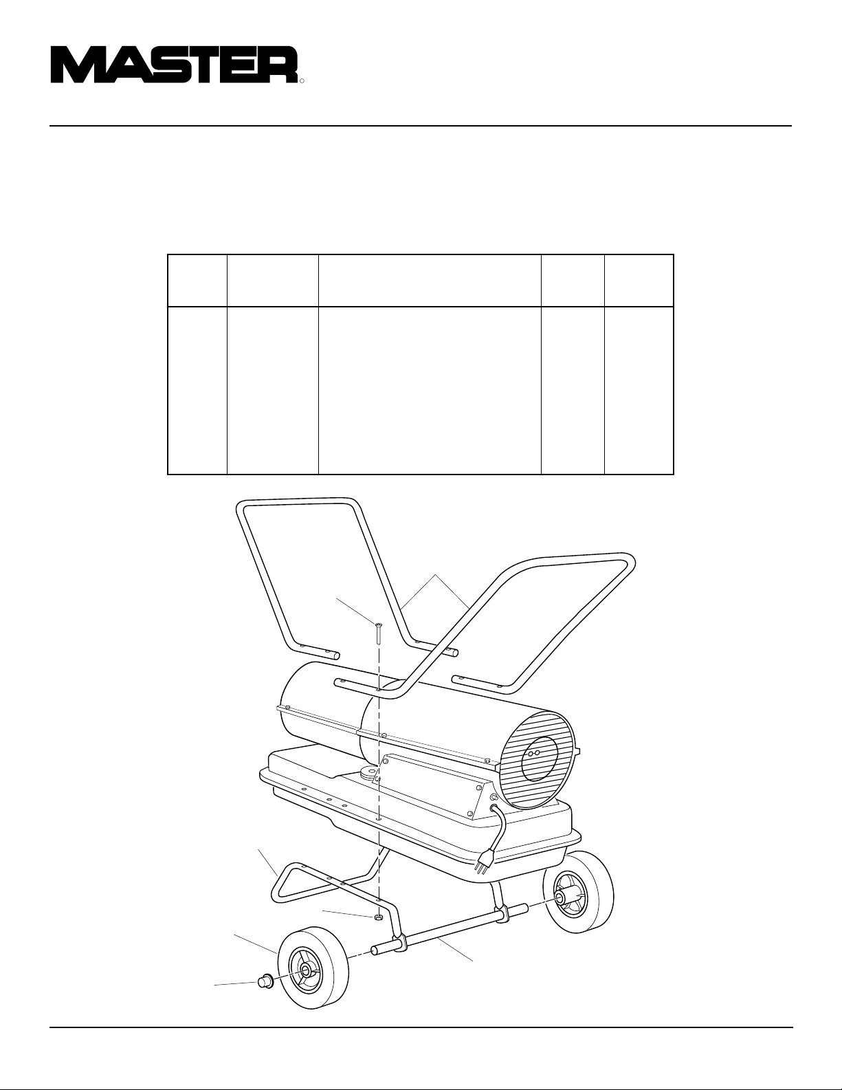
R
CALENTADORES PORTATILES DE AIRE FORZADO
RUEDAS Y ASAS
PARA MODELOS DE
29,3 Y 44 KW (100.000 Y
150.000 BTU/HR)
CANT. CANT.
29,3 kW 44 kW
CLAVE NO. PIEZA DESCRIPCION (100.000) (150.000)
1 HA2203 Asas 2 —
HA2204 Asas — 2
2 M12345-33 Tornillo, #10-24 x 1 3/4" 8 8
3 M12342-3 Bastidor de soporte de las ruedas 1 —
M12831-3 Bastidor de soporte de las ruedas — 1
4 NTC-3C Tuerca hexagonal, #10-24 8 8
5 097896-03 Rueda 2 2
6 M28526 Tuerca ciega 2 2
7 M51015-01 Eje 1 —
M16801-2 Eje — 1
1
2
3
4
5
7
6
22
104468
Page 47

ACCESORIOS
Obtenga los accesorios a través del concesionario en su localidad.
MANOMETRO DE AIRE HA1180
Para todos los modelos. Herramienta especial para comprobar la presión de la bomba.
MANUAL DEL PROPIETARIO
JUEGO DE RUEDAS Y
AGARRADERAS ESTANDAR
- HA1206
JUEGO DE RUEDAS Y ASA
DE SERVICIO SEVERO HA1202
Para aplicaciones de servicio severo. Hace
el calentador más portátil y conveniente.
Para los modelos de 10,2/20,5 kW (35.000/
70.000 Btu/hr)
Incrementa la portabilidad y comodidad de
manejo del calentador. Fácil de armar. Para
modelos de 10,2/20,5 kW (35.000 a 70.000
Btu/Hr).
104468
23
Page 48

GARANTIA Y REPARACIONES
CERTIFICADO DE GARANTIA LIMITADA DE 90 DIAS PARA EQUIPO GENERAL
DESA International garantiza que los productos nuevos que
vende carecen de defectos en el material y fabricación por un
período de noventa días a partir de la fecha de entrega al primer
usuario y sujeto a las condiciones siguientes:
Las obligaciones y responsabilidades de DESA International
bajo esta garantía se limitan expresamente a la reparación o el
reemplazo a discreción de DESA International de los
componentes que a juicio de DESA International y posterior a
la inspección tenían defectos de material o fabricación al ser
despachados de la fábrica. Tales componentes serán
suministrados sin costo al usuario, al establecimiento
comercial o a un centro de servicio autorizado por la fábrica o
fábrica durante horas regulares de trabajo. La garantía no cubre
los componentes o accesorios de productos no fabricados por
DESA International, los cuales se encuentran amparados por
garantías de sus fabricantes respectivos, ni cubre el
mantenimiento normal (tal como los ajustes de presión) ni los
repuestos normales (tales como filtros y bujías). Las piezas de
repuesto o reparación instaladas en el producto amparado bajo
esta garantía se garantizan únicamente por la porción restante
del período de la presente garantía, como si tales fueran
componentes originales de dicho producto. DESA INTERNATIONAL NO OFRECE NINGUNA GARANTIA
EXPRESA ADICIONAL. HASTA EL PUNTO QUE
ESTABLECE LA LEY, DESA INTERNATIONAL NO
OFRECE GARANTIA IMPLICITA ALGUNA Y NO
GARANTIZA LA IDONEIDAD NI LA
COMERCIABILIDAD DE ESTE PRODUCTO PARA
ALGUN PROPOSITO ESPECIFICO. EN TODO CASO,
LAS GARANTIAS IMPLICITAS, INCLUYENDO LAS DE
COMERCIABILIDAD E IDONEIDAD PARA UN
PROPOSITO ESPECIFICO, SE LIMITAN A LA
DURACION DE LA PRESENTE GARANTIA EXPRESA.
Los costos de transporte, costos de instalación, honorarios,
impuestos u otros recargos correrán por cuenta del usuario. La
obligación de DESA International bajo esta garantía limitada
no incluye responsabilidad por daños o retrasos directos,
indirectos, fortuitos o consecuentes. Si DESA International
así lo solicita, los productos sobre los cuales se efectúe algún
reclamo deberán ser devueltos, a flete pagado por el usuario,
a la fábrica. El uso indebido de este producto, incluyendo su
uso después del descubrimiento de piezas defectuosas o
desgastadas, el uso más allá de la capacidad, la sustitución de
piezas por componentes no aprobados por DESA International o cualquier otra alteración o reparación por terceros que
a juicio de DESA International afecte este producto de forma
material y adversa, anulará la presente garantía.
NINGUN EMPLEADO O REPRESENTANTE CUENTA
CON LA AUTORIDAD PARA ALTERAR ESTA
GARANTIA EN MODO ALGUNO NI PARA OTORGAR
GARANTIAS ADICIONALES A MENOS QUE TAL
ALTERACION SE HAGA POR ESCRITO Y SEA
FIRMADA POR UN OFICIAL EN LA CASA MATRIZ DE
DESA INTERNATIONAL.
Printed in U.S.A.
SERVICIO DE GARANTIA
Siempre especifique los números de modelo y de serie al
comunicarse con la fábrica.
Nos reservamos el derecho de enmendar estas
ESPECIFICACIONES en cualquier momento y sin previo
aviso. La única garantía aplicable al producto es nuestra
garantía estándar dada por escrito. No se ofrece ninguna
garantía adicional, ni expresa ni implícita.
Se puede obtener un Manual de servicio solicitándolo por
correspondencia al Departamento de servicios técnicos a
la dirección siguiente:
DESA
INTERNATIONAL
Corporate Headquarters
2701 Industrial Drive
P.O. Box 90004
Bowling Green, Kentucky 42102-9004 EE.UU.
 Loading...