

Page 1
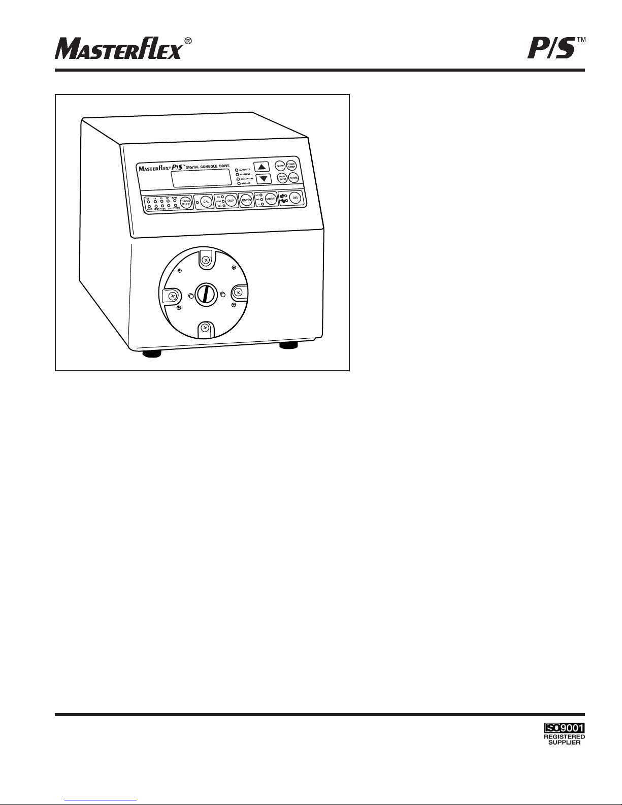
850-3010 pump drive.
OPERATING MANUAL:
PUMP DRIVE
MODE D’EMPLOI:
ENTRAÎNEMENT DE
POMPE
BETRIEBSANLEITUNG:
PUMPENANTRIEB
MANUAL DE FUNCIONAMIENTO:
MOTOR DE BOMBA
MANUALE DI ISTRUZIONI:
UNITÀ DI
CONTROLLO POMPA
Thermo Fisher Scientific
1-800-637-3739 (U.S. and Canada only)
11 (847) 381-7050 (Outside U.S.) • (847) 381-7050 (Local)
www.thermo.com • bar.barnant@thermofisher.com
Model No.
N° de modèle
Modellnummer
Número de modelo
Modello nº
850-3010
A-1299-7004
Edition02
Page 2

2
Page 3
TABLE OF CONTENTS
Title Page
SAFETY PRECAUTIONS . . . . . . . . . . . . . . . . . . . . . . . . . . . . . . . . . . . . . . . . . . . . . . . . . . . . . . . . . . . . . . . . . . . . . . 3
INTRODUCTION . . . . . . . . . . . . . . . . . . . . . . . . . . . . . . . . . . . . . . . . . . . . . . . . . . . . . . . . . . . . . . . . . . . . . . . . . . . . . 4
CONTROL/DISPLAY FUNCTIONS . . . . . . . . . . . . . . . . . . . . . . . . . . . . . . . . . . . . . . . . . . . . . . . . . . . . . . . . . . . . . . . 4
SETUP AND DRIVE OPERATION . . . . . . . . . . . . . . . . . . . . . . . . . . . . . . . . . . . . . . . . . . . . . . . . . . . . . . . . . . . . . . . . 5
Automatic Start Enable/Disable . . . . . . . . . . . . . . . . . . . . . . . . . . . . . . . . . . . . . . . . . . . . . . . . . . . . . . . . . . . . . . . . 5
CALIBRATION . . . . . . . . . . . . . . . . . . . . . . . . . . . . . . . . . . . . . . . . . . . . . . . . . . . . . . . . . . . . . . . . . . . . . . . . . . . . . . . 5
Maximum Flow Rate (“OTHER” Tubing) . . . . . . . . . . . . . . . . . . . . . . . . . . . . . . . . . . . . . . . . . . . . . . . . . . . . . . . . . 5
DISPENSE/COPY . . . . . . . . . . . . . . . . . . . . . . . . . . . . . . . . . . . . . . . . . . . . . . . . . . . . . . . . . . . . . . . . . . . . . . . . . . . . 6
Keypad Lockout Enable/Disable . . . . . . . . . . . . . . . . . . . . . . . . . . . . . . . . . . . . . . . . . . . . . . . . . . . . . . . . . . . . . . . 6
REMOTE CONTROL . . . . . . . . . . . . . . . . . . . . . . . . . . . . . . . . . . . . . . . . . . . . . . . . . . . . . . . . . . . . . . . . . . . . . . . . . . 6
Remote Control Setup . . . . . . . . . . . . . . . . . . . . . . . . . . . . . . . . . . . . . . . . . . . . . . . . . . . . . . . . . . . . . . . . . . . . . . . 6
TROUBLESHOOTING AND MAINTENANCE . . . . . . . . . . . . . . . . . . . . . . . . . . . . . . . . . . . . . . . . . . . . . . . . . . . . . . . 8
Fuse Replacement . . . . . . . . . . . . . . . . . . . . . . . . . . . . . . . . . . . . . . . . . . . . . . . . . . . . . . . . . . . . . . . . . . . . . . . . . . 8
Shaft Seal Inspection . . . . . . . . . . . . . . . . . . . . . . . . . . . . . . . . . . . . . . . . . . . . . . . . . . . . . . . . . . . . . . . . . . . . . . . .8
Troubleshooting . . . . . . . . . . . . . . . . . . . . . . . . . . . . . . . . . . . . . . . . . . . . . . . . . . . . . . . . . . . . . . . . . . . . . . . . . . . . 9
Cleaning . . . . . . . . . . . . . . . . . . . . . . . . . . . . . . . . . . . . . . . . . . . . . . . . . . . . . . . . . . . . . . . . . . . . . . . . . . . . . . . . . 11
Replacement Parts and Accessories . . . . . . . . . . . . . . . . . . . . . . . . . . . . . . . . . . . . . . . . . . . . . . . . . . . . . . . . . . . 11
SPECIFICATIONS . . . . . . . . . . . . . . . . . . . . . . . . . . . . . . . . . . . . . . . . . . . . . . . . . . . . . . . . . . . . . . . . . . . . . . . . . . . 11
WARRANTY . . . . . . . . . . . . . . . . . . . . . . . . . . . . . . . . . . . . . . . . . . . . . . . . . . . . . . . . . . . . . . . . . . . . . . . . . . . . . . . . 12
PRODUCT RETURN . . . . . . . . . . . . . . . . . . . . . . . . . . . . . . . . . . . . . . . . . . . . . . . . . . . . . . . . . . . . . . . . . . . . . . . . . 12
TECHNICAL ASSISTANCE . . . . . . . . . . . . . . . . . . . . . . . . . . . . . . . . . . . . . . . . . . . . . . . . . . . . . . . . . . . . . . . . . . . . 12
SAFETY PRECAUTIONS
DANGER: High vo l t ag e s exist and are accessible in the C o n s o l e Dr i v e . Use extreme c a u t i o n
when servicing internal components.
WARNINGS: Tubing breakage may result in fluid being sprayed from pump. Use appropriate measures
to protect operator and equipment.
Turn drive off before removing or installing tubing. Fingers or loose clothing could get caught in
drive mechanism.
CAUTIONS: Power must be turned off before connecting the external remote control cable to prevent
damage to the drive.
Do not stack drives. Keep 3” minimum distance around and above drive for proper cooling.
WARNING: PRODUCT USE LIMITATION
This product is not designed for, nor intended for use in, patient-connected applications, including, but not limited
to, medical and dental use, and, accordingly, has not been submitted for FDA approval. If drive is used in a manner
not specified in this manual the protection provided by the equipment may be impaired.
MASTERFLEX - Reg TM Cole-Parmer
Trademarks bearing the ® symbol in this publication are registered in the U.S. and in other countries.
3
Page 4
INTRODUCTION
The Console Drive controls the speed of MASTERFLEX®P/STMPump Heads to provide flow rates from 0.10 to
3400 mL/min or 0.001 to 54 gallons/hr.
Mount up to 2 MASTERFLEX P/S Pump Heads and all MASTERFLEX-compatible Pump Heads.
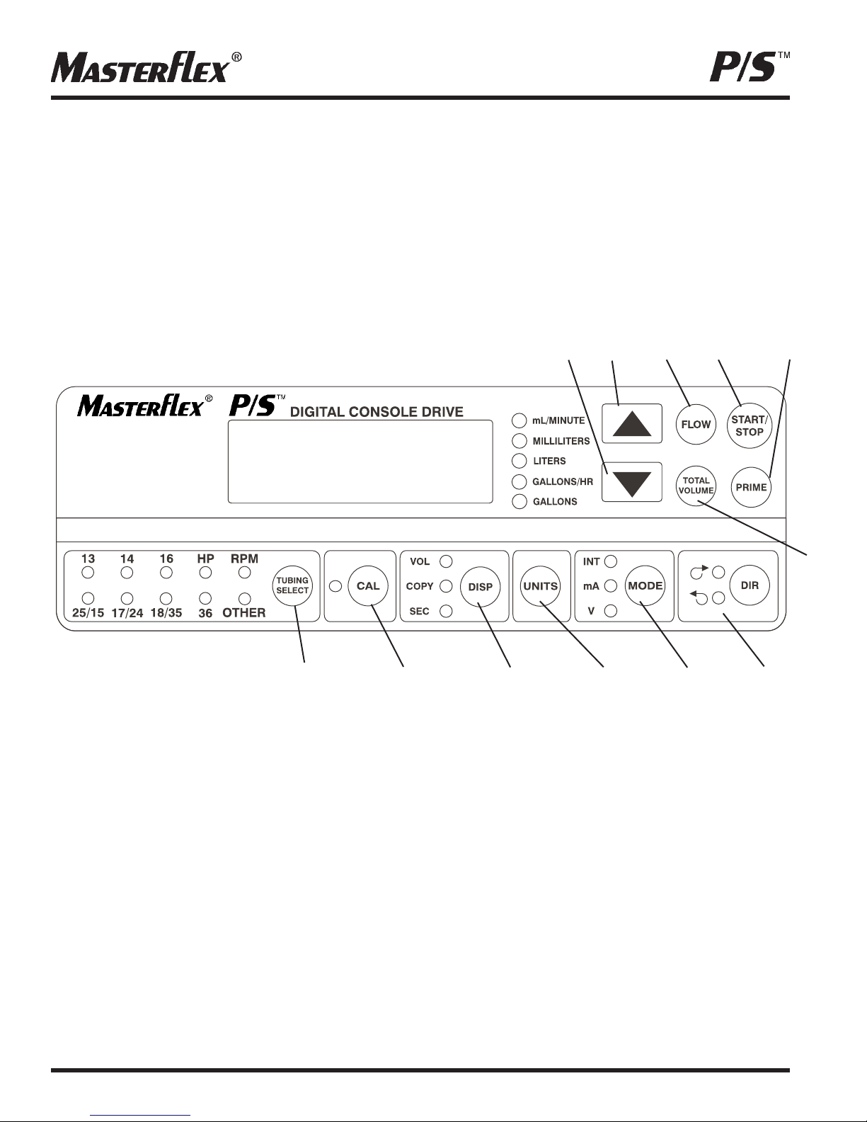
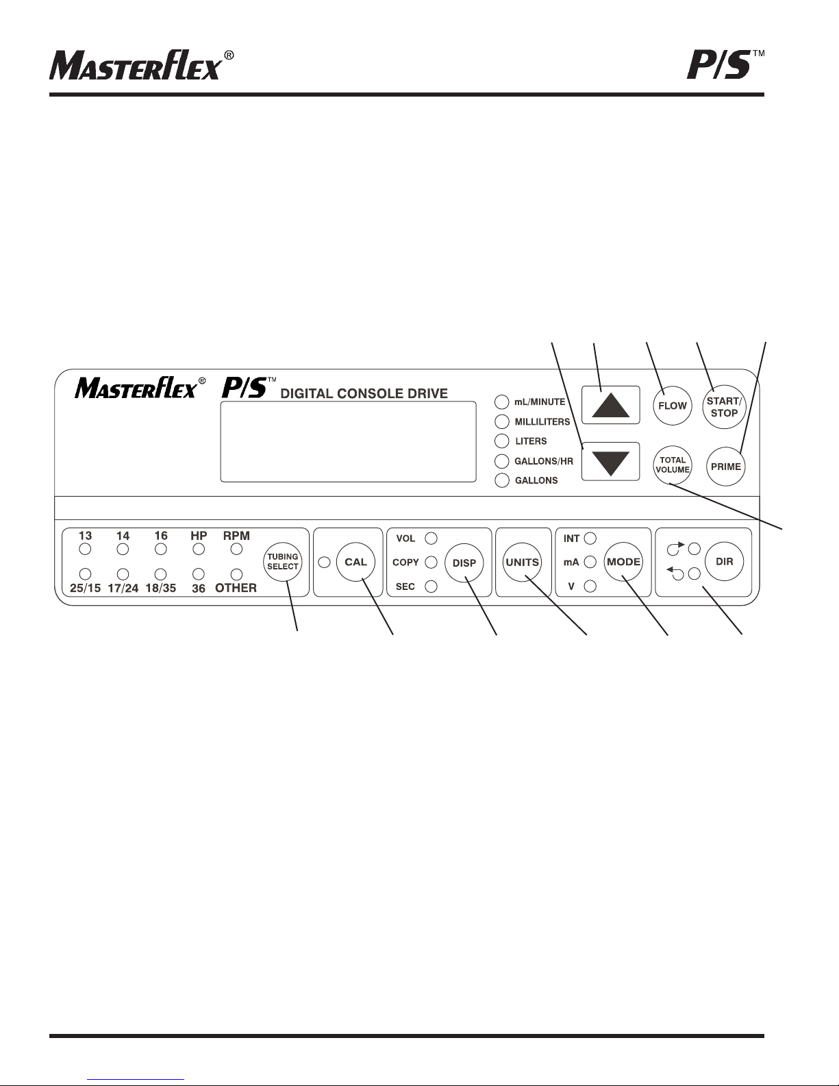
CONTROL/DISPLAY FUNCTIONS
Press keys to activate function. Use INC/DEC (▲,▼) arrow keys to correct/change a flashing display.
Press any key to enter new values.
AB C D E
F
Figure 1
LK JIHG
A. DOWN ARROW (DECREMENT)—Decrease value of a flashing display.
B. UP ARROW (INCREMENT)—Increase value of a flashing display.
C. FLOW CONTROL—Set flow rate for selected tubing size. To change flow rate, press ▲ or ▼ arrows.
(If pump is running, its speed will change with new settings.)
D. START/STOP—Start/Stop motor.
E. PRIME—Run pump at full speed to fill or clear lines.
F. TOTAL VOLUME—Display cumulative dispensed volume.
G.DIRECTION—To change motor direction.
H. MODE SELECT—INT for internal control; mA for remote current control; V for remote voltage control.
I. UNITS—Select between metric (milliliters and liters) and English (U.S. gallons) displayed units.
J. DISPENSE/COPY—Select dispensed volume, copy volume, or the dispense/copy interval.
K. CAL CONTROL—Refine built-in calibration using a measured volume.
L. TUBING SELECT—Select tubing size.
4
Page 5

SETUP AND DRIVE OPERATION
1. Mount Pump Head and load tubing (see Pump Head manual).
NOTE: The Pump Head may be oriented in any of four (4) positions, 90° apart. Rotation is accomplished by removing and
reinstalling the front plate, to which pumps are mounted. See “Troubleshooting and Maintenance, Shaft Seal Inspection”
for directions.
2. Turn drive on and select tubing size by pressing “TUBING SELECT.”
NOTE: If CAL LED is lit, that tubing size has been previously field calibrated. If LED is not lit, the drive is operating with the
built-in factory calibration. To clear a field calibration, press and hold the CAL key until the CAL light goes out. This will take
about 3 seconds. To recalibrate for better accuracy, see Calibration section.
3. Select MODE (INT, mA, V).
4. Select motor DIRection (CW or CCW).
5. PRIME and CALibrate the pump (if required).
6. Press FLOW key and watch display to set the flow rate with INC/DEC (▲, ▼) keys.
7. Press START/STOP key to begin pumping.
NOTE: While in INTernal mode, drive will not restart automatically after a brownout or powerout condition unless operator
changes default setting. If speed is being controlled by an external signal, drive will automatically start with a non-zero speed
command in power-up.
AUTOMATIC START ENABLE/DISABLE (Internal mode only)
Press and hold START/STOP on power-up. After five (5) seconds, display will change to all dashes. Then, while
holding START/STOP, press PRIME five (5) times. Display will flash “ON” or “OFF”. Use INC/DEC (▲, ▼) arrow keys to
enable or disable automatic start option. Press any other key to exit. When “ON” is selected, drive will start automatically at
power-up if it was “ON” when powered down.
CALIBRATION
Use only MASTERFLEX precision tubing with MASTERFLEX pumps to ensure
optimum performance. Use of other tubing may void applicable warranties.
1. Select correct tubing size and flow rate.
2. Press CAL; calibration volume appears.
3. Press START/STOP; the pump will use its stored memory to dispense the specified calibration sample quantity.
The pump will stop automatically.
4. Weigh/measure the sample.
5. Use INC/DEC (▲, ▼) arrow keys to correct the flashing display.
NOTE: If the adjusted calibration is too great, “Err” will appear in the display. If this occurs, press the CAL control and
repeat the calibration procedure. The microprocessor will retain one special calibration value per tubing size, even
when power is turned off. The next calibration will replace the existing value.
6. Press TUBING SELECT to exit the calibration cycle.
MAXIMUM FLOW RATE (“OTHER” Tubing)
1. To set the maximum flow rate for non-standard Pump Heads or “OTHER” tubing sizes, press CAL, then FLOW.
The maximum flow rate will then flash on the display.
2. Use INC/DEC (▲, ▼) arrow keys to change flow rate.
3. Press TUBING SELECT to exit
5
Page 6
DISPENSE/COPY
A first press of the DISP key results in the last entered dispense volume being displayed. The VOL annunciator will
illuminate and flash. The INC/DEC (▲, ▼) keys are used to change the dispense volume, if desired.
The START/STOP key then initiates delivery of the set volume. The amount remaining to be dispensed will be
displayed during countdown. Resetting cumulative dispensed volume can be done by pressing and holding the TOTAL
VOLUME key until zero is displayed (3 seconds). Display flashes “99999” when cumulative volume is greater than
99999. The dispense function is exited by the FLOW key.
A second press of the DISP key causes the COPY annunciator to illuminate and flash. The START/STOP key is then
used to deliver the desired volume without the need to know the volume in specific units. A third press of the DISP key
enters the volume dispensed. The COPY annunciator stops flashing. The START/STOP key is then used to initiate
delivery of the copied volume. The number of copies dispensed is displayed after each dispense. The maximum
number of copies is 99999. The START/STOP key is used to pause the copy dispense during dispensing; copy
dispense can then be continued using the START/STOP key.
A fourth press of the DISP key results in the last entered dispense interval being displayed. The SEConds annunciator
will illuminate and flash. The INC/DEC (▲, ▼) keys are used to change the time interval between dispenses, if desired,
from 0 to 99999 seconds. The START/STOP key then initiates delivery for the set volume, with the drive automatically
initiating a new dispense after each time out. The remaining time will be displayed during countdown. The START/STOP
key is used to stop the dispense cycle. A time of 0 seconds (default) will require initiation of each dispense through the
START/STOP key or the Remote START/STOP contact closure.Pressing the DISP key a fifth time exits this mode.
KEYPAD LOCKOUT ENABLE/DISABLE
Press/hold FLOW. After five (5) seconds, display changes to all dashes. While holding FLOW, press PRIME five (5) times.
REMOTE CONTROL
Selectable input (0–20 mA, 4–20 mA, 0–10V DC )
±0.5% linearity control
±50V common mode range with earth ground
START/STOP; CW/CCW; PRIME via contact closure
REMOTE CONTROL SETUP
1. Place the power switch in the off position.
CAUTION: Power must be turned off before connecting the external remote control cable to prevent
damage to the drive.
2. Connect the cable from the external remote control to the mating receptacle on the rear panel.
3. Select type of remote control input and output required as follows:
a. Press and hold the MODE control while turning the power switch to the on position. After two seconds, release
the MODE control. The initial display will show: “inP”. After two seconds, the display shows either 0–20 or 4–20.
NOTE: Press the INC (▲) or DEC (▼) arrow keys to select between 4–20 and 0–20 for current loop control.
b. Press the MODE control again. The initial display will show: “out”. After two seconds, the display shows either
0–10, 0–20, or 4–20.
NOTE: Press the INC (▲) or DEC (▼) arrow keys to select between 4–20, 0–20, or 0–10 for current loop
or voltage output.
4. Press the MODE control to select mode of operation. The LEDs indicate the selected mode. Select either mA or V.
6
Page 7
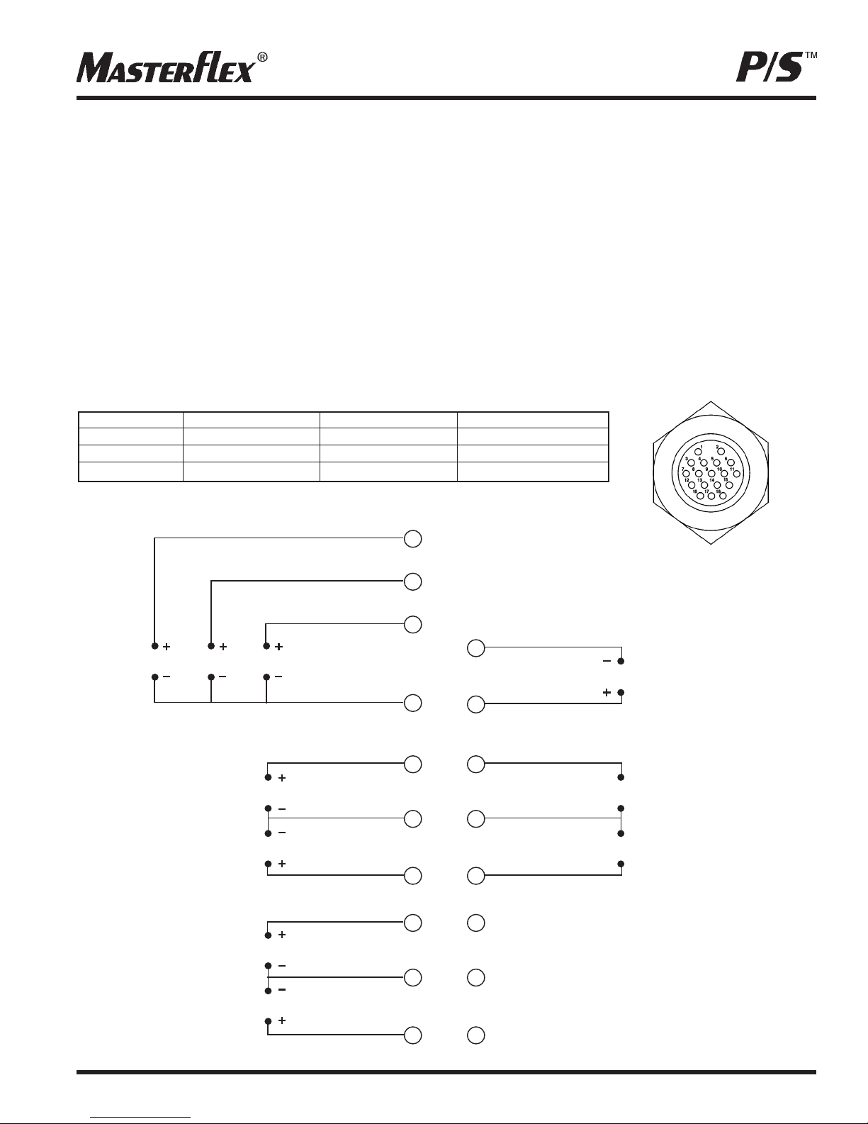
3
8
4
6
14
5
1
7
9
2
11
13
15
16
17
18
10
12
START/STOPCW/CCWPRIME
RED/YELLOW
BLUE
GREEN
YELLOW
WHITE
ORANGE
BLACK
BROWN
VIOLET
RED
GREY
TAN
PINK
RED/GREEN
RED/BLACK
N.C.
N.C.
N.C.
OUTPUT
0-20mA; 4-20mA
INPUT
0-20mA; 4-20mA
INPUT
0-10V
OUTPUT
0-10V
TACH OUTPUT
MOTOR RUNNING
N.O. CONTACT
MOTOR RUNNING
N.C. CONTACT
NOTE: If using only remote START/STOP, PRIME and/or CW/CCW, the MODE control can be set to any of the
three positions.
5. To adjust the voltage or current scaling for other than zero to full scale, Press and hold the MODE key while
pressing the FLOW key. This display will show “LO” for 2 seconds and then a flow rate. Use the INC/DEC (▲, ▼)
arrow keys to set the minimum control level. Press the FLOW key again. The display will show “HI” for 2 seconds
and then a flow rate. Use the INC/DEC (▲, ▼) arrow keys to set the maximum control level. Press any other key to
exit. The same scaling will be used for both input and output levels.
NOTE: Tubing size should be selected before adjusting the voltage or current scaling.
To provide sufficient hysteresis between minimum speed and off, a 0.2 mA and 0.1 V offset is added to the current
and voltage inputs and outputs as shown in the following table. This offset is only added when the input/output
scaling is set with a minimum speed of zero (default)
Speed (rpm) 4-20 mA In/Out 0-20 mA In/Out 0-10 V In/Out
0 4-4.2 mA 0-0.2 mA 0-0.1 V
1 4.2263 mA 0.233 mA 0.1165 V
600 20 mA 20 mA 10V
NOTE:Colors are those of
Remote Cable 77300-32.
850-3010
Figure 2
7
Page 8
TROUBLESHOOTING AND MAINTENANCE
A
B
C
D
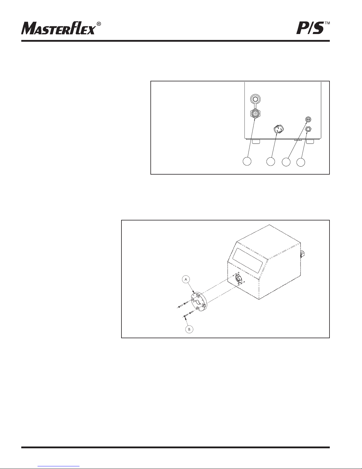
FUSE REPLACEMENT
1. Place the power switch in the off position.
2. Disconnect the AC power input line cord
from the attached line and receptacle.
3. Remove and check the fuse and replace if
defective
4. Reconnect the AC power input line cord to
the receptacle.
A. External receptacle for
remote control
B. IEC 320 Power cord
C. T3.15A Fuse CAUTION:
Do not substitute.
D. Power switch—All
settings are retained
in memory.
SHAFT SEAL INSPECTION
Figure 3
1. Remove any pump(s) attached to the front
of the drive. Clean any foreign material from
the outside diameter of the drive shaft.
2. Remove the (4) screws (Item B) that hold the front plate assembly (Item A) to the drive, and pull the front plate
assembly off the drive. #8-32 screws may be installed in the pump-mounting holes to provide handles for pulling the
plate assembly off. Retain Item B screws for Step 8. DO NOT substitute other screws.
3. Turn the front plate over so that
the seal side is visible. Wipe the
elastomeric seal lips with a clean
cloth to remove any grease and
foreign material.
A. Front plate assembly
B. Front plate assembly
screws (4)
4. Inspect the elastomeric seal lips
for tears or cuts or missing material. If any of the mentioned conditions exist, replace the seal
assembly using the 07575-01
replacement seal kit.
5. Wipe the exposed part of the
drive shaft with a clean cloth.
Wipe from the drive outward, to
Figure 4
remove all grease and foreign
matter.
6. Inspect the shaft surface in the area touched by the seal. Look for a rough finish, or grooves parallel to the shaft
length. If the shaft end is worn or damaged, as described above, replace the gear and shaft with the 07575-02 kit.
A polished groove, concentric to the outside of the shaft, is not a defect, as long as the groove is no more than
0.002 inches deep.
7. Prior to re-assembly, re-lubricate the shaft and the seal with the food-grade lubricant provided with the unit.
CAUTION: Do not contaminate the lubricant in the container, on the shaft or on the seal with foreign material.
Failure to observe this precaution may result in damage to the seal and premature failure of the seal.
8. Slide the front plate assembly back over the shaft and onto the locating pins, in the orientation desired.
(4 configurations, each 90 degrees of rotation apart, are possible). Reinstall the 4 screws, removed in Step 2 above.
CAUTION: No foreign matter should be allowed under the gasket on the back of the front plate or under
the heads of the screws. Failure to observe this precaution may result in leakage during washdown of the drive.
8
Page 9

TROUBLESHOOTING
SYMPTOM
A. Motor does not rotate.
Display does not light.
B. Motor does not rotate.
Display lights.
CAUSE
A. No power.
B1. Defective remote control.
REMEDY
1. Check fuse and replace if
defective (Fig. 3).
2. Check that unit is plugged into
a live line.
3. Check connection of power
cord.
4. Check the line cord for continuity
and replace if defective.
5. Return for servicing.
1. Place power switch in
off position.
2. Check that remote cable
connector is inserted fully into
the receptacle (Fig. 2 and 3)
3. If motor still does not rotate,
select INTernal with the MODE
control and press the
START/STOP control (Fig. 1).
4. If the motor rotates, replace the
remote control with similar unit.
If motor does not rotate, return
drive for servicing.
B2. MODE control not
properly set.
1. Check that the MODE control
is set to INT for operation with
front panel control or to mA
or V for operation with remote
control (Fig. 1).
2. If motor still does not rotate,
return for servicing.
Troubleshooting continued on page 10.
9
Page 10

TROUBLESHOOTING (Continued)
If an error message is displayed, refer to the following list for possible corrective actions you can take. If these do not
correct the problem, contact your dealer.
ERROR MESSAGE
“Err 2”
“Err 3”
“Err 5”
“Err 12”
“Err 7”
“Err 10”
“Err 11”
CAUSE
Motor over-speed
Overload
Bad data. Operator parameters set
to default values.
Voltage out of range
REMEDY
1. Clear by pressing any key.
2. Check for proper tube loading
and pump operation.
3. Return unit for repair if the
error persists.
1. Clear by pressing any key.
2. Check for proper tube loading
and pump operation.
3. Return unit for repair if the
error persists.
1. Clear by pressing any key.
2. Reprogram operator parameters.
3. Return unit for repair if the
error persists.
1. Clear by pressing any key.
2. Check that AC line voltage is
within specified voltage ranges.
3. Return unit for repair if AC
line voltage is correct and the
error persists.
“Err 14”
All other errors
10
Over temperature
Internal error or failure.
1. Check for heat sources or
obstructions to cooling.
2. Check for proper tube loading
and pump operation.
3. Allow unit to cool. Clear by
pressing any key.
4. Return unit for repair if no
cause for overheating is found
and the error persists.
1. Clear (if possible) by turning
power off and on.
2. Return unit for repair if the
error persists.
Page 11

CLEANING
Keep the drive enclosure clean with mild detergents. Do not immerse.
REPLACEMENT PARTS & ACCESSORIES
Description Part Number Description Part Number
Fuse—T3.15A 5 x 20 mm 77500-25 Footswitch 07595-43
Hand-held remote control 07592-83 Remote control cable,
Replacement Seal Kit 07575-01 25 ft (7.62 m) 77300-32
Replacement Gear and Shaft Kit 07575-02
SPECIFICATIONS
Output:
Speed: 1 to 600 rpm
Torque output, Maximum:
Continuous 180 oz-in (13 kg•cm)
Start-up 540 oz-in (39 kg•cm)
Speed regulation:
Line ±0.25% F.S.
Load ±0.25% F.S.
Drift ±0.25% F.S.
Display: Five-digit, seven-segment LED
Remote outputs: Voltage speed output (0–10V DC @ 1 kΩ min)
Current speed output (0–20 mA or 4–20 mA @ 0–600 Ω)
Tach output (TTL, 10 to 6000 Hz, 50% duty cycle 10 Hz/rpm)
Motor running output
(N.O. & N.C. contact closure, 1A @ 28V AC/DC)
Input:
Supply voltage limits: Dual voltage—Automatically selected
90 to 130 Vrms @ 50/60 Hz, or 200 to 260 Vrms @ 50/60 Hz
Current, max.: 2.2A @ 115 Vrms, or 1.1A @ 230 Vrms
Remote Inputs: START/STOP, CW/CCW, PRIME (Contact closure)
Voltage input (0–10V DC @ 10 kΩ)
Current input (0–20 mA or 4–20 mA @ 250 Ω)
Construction:
Dimensions (L × W × H): 14.0″ × 9″ × 9.3″ (35 cm × 23 cm × 24 cm)
Weight: 22 lb (10 kg)
Enclosure Rating: IP 66 per IEC 60529/NEMA 4 X - indoor use
Environment:
Temperature, Operating: 0° to 40°C (32° to 104°F)
Temperature, Storage: –25° to 65°C (–13° to 149°F)
Humidity (non-condensing): 10% to 100%
Altitude: Less than 2000 m
Pollution Degree: Pollution Degree 3
(Indoor use—sheltered locations)
Chemical Resistance: Enclosure is 316 stainless steel
Compliance: UL508C, CSA C22.2, No. 14
(For CE Mark):
EN61010-1 (EU Low Voltage Directive) and
EN61326-1 (EU EMC Directive
11
Page 12
WARRANTY
Use only MASTERFLEX precision tubing with MASTERFLEX pumps to ensure optimum performance. Use of
other tubing may void applicable warranties.
This product is warranted against defects in material or workmanship, and at the option of the manufacturer or distributor, any defective product will be repaired or replaced at no charge, or the purchase price will be refunded to the purchaser, provided that: (a) the warranty claim is made in writing within the period of time specified on this warranty
card, (b) proof of purchase by bill of sale or receipted invoice is submitted concurrently with the claim and shows that
the product is within the applicable warranty period, and (c) the purchaser complies with procedures for returns set
forth in the general terms and conditions contained in the manufacturer's or distributor's most recent catalog.
This warranty shall not apply to: (a) defects or damage resulting from: (i) misuse of the product, (ii) use of the product in
other than its normal and customary manner, (iii) accident or neglect, (iv) improper testing, operation, maintenance,
service, repair, installation, or storage, (v) unauthorized alteration or modification, or (b) post-expiration dated materials.
THIS WARRANTY IS THE EXCLUSIVE REMEDY OF THE PURCHASER, AND THE MANUFACTURER AND DISTRIBUTOR DISCLAIM ALL OTHER WARRANTIES, WHETHER EXPRESS, IMPLIED, OR STATUTORY, INCLUDING
WITHOUT LIMITATION, WARRANTIES OF MERCHANTABILITY AND FITNESS FOR A PARTICULAR PURPOSE.
NO EMPLOYEE, AGENT, OR REPRESENTATIVE OF THE MANUFACTURER OR DISTRIBUTOR IS AUTHORIZED
TO BIND THE MANUFACTURER OR DISTRIBUTOR TO ANY OTHER WARRANTY. IN NO EVENT SHALL THE
MANUFACTURER OR DISTRIBUTOR BE LIABLE FOR INCIDENTAL, INDIRECT, SPECIAL OR CONSEQUENTIAL
DAMAGES.
The warranty period for this product is two (2) years from date of purchase.
PRODUCT RETURN
To limit charges and delays, contact the seller or Manufacturer for authorization and shipping instructions before
returning the product, either within or outside of the warranty period. When returning the product, please state the
reason for the return. For your protection, pack the product carefully and insure it against possible damage or loss.
Any damages resulting from improper packaging are your responsibility.
TECHNICAL ASSISTANCE
If you have any questions about the use of this product, contact the Manufacturer or authorized seller.
Thermo Fisher Scientific
1-800-637-3739 (U.S. and Canada only)
11 (847) 381-7050 (Outside U.S.)
(847) 381-7050 (Local)
www.thermo.com
bar.barnant@thermofisher.com
12
Printed in U.S.A.
Page 13
TABLE DES MATIERES
Titre Page
MESURES DE SECURITE .......................................................................................................................................... 3
INTRODUCTION........................................................................................................................................................ 14
FONCTIONS DE CONTRÔLE/AFFICHAGE.............................................................................................................. 15
CONFIGURATION ET FONCTIONNEMENT DE L’ENTRAÎNEMENT........................................................................ 15
Démarrage Automatique Activé/Désactivé .......................................................................................................... 16
CALIBRAGE .............................................................................................................................................................. 16
Débit Maximum (Conduites “AUTRES” [“OTHER”]).............................................................................................. 16
DISTRIBUTION/RÉPÉTITION.................................................................................................................................... 17
Verrouillage du pave numérique Activé/Désactivé .............................................................................................. 17
COMMANDE À DISTANCE........................................................................................................................................ 17
Configuration de la Commande à Distance.......................................................................................................... 17
DEPANNAGE ET MAINTENANCE ............................................................................................................................ 17
Remplacement de Fusible .................................................................................................................................... 19
Inspection de la Boîte d'étanchéité........................................................................................................................19
Dépannage .......................................................................................................................................................... 19
Nettoyage ............................................................................................................................................................ 20
Pièces détachées et accessoires ........................................................................................................................ 22
SPECIFICATIONS...................................................................................................................................................... 22
GARANTIE ................................................................................................................................................................ 23
RETOUR PRODUIT .................................................................................................................................................. 23
ASSISTANCE TECHNIQUE ......................................................................................................................................23
Francais
MESURES DE SECURITE
DANGER: Il existe des hautes tensions et elles sont accessibles depuis la Console de l’entraînement.
Prenez toutes les précautions requises lors de la maintenance/dépannage de composants
internes.
AVERTISSEMENTS: La rupture des conduits peut entraîner la fuite de liquide depuis la pompe. Mettez en
place les mesures adéquates pour protéger l'opérateur et les équipements. Coupez
l’entraînement avant de retirer ou d’installer des conduites. Les doigts ou des vêtements
amples peuvent se prendre dans le mécanisme d’entraînement.
PRECAUTIONS: L’alimentation doit être coupée avant de connecter la télécommande externe afin de ne
pas endommager l’entraînement. N’empilez pas les entraînements de pompe. Gardez au
moins 7 à 8 cm autour et au dessus de l’entraînement pour un refroidissement efficace.
AVERTISSEMENT : LIMITE D’UTILISATION DU PRODUIT
Ce produit n’a pas été conçu ou prévu pour être utilisé dans des applications connectées à des malades, incluant,
mais ne se limitant pas à, l’utilisation médicale ou dentaire et, par conséquent, n’a pas été soumis à une approbation
FDA (Food and Drug Administation - Fédération américaine des aliments et drogues). Si l’entraînement est utilisé
d’une façon non spécifiée dans ce manuel, la protection fournie par cet équipement pourrait être endommagée.
13
Page 14
INTRODUCTION
M
La Console d’Entraînement contrôle la vitesse des têtes de pompe MASTERFLEX®P/S
0.10 à 3400 mL/min.
Extensible à 2 têtes de pompe MASTERFLEX P/S et à toutes les têtes de pompe compatibles MASTERFLEX.
T
pour fournir des débits de
FONCTIONS DE CONTRÔLE/AFFICHAGE
Appuyez sur les touches pour activer une fonctionnalité. Utilisez les touches flèches INC/DEC (▲, ▼) pour corriger/modifier
une valeur affichée clignotante. Appuyez sur n’importe quelle touche pour rentrer de nouvelles valeurs.
AB C D E
F
Figure 1
LK JIHG
A. FLÈCHE VERS LE BAS (DECREMENTER) - Décrémente une valeur affichée clignotante.
B. FLÈCHE VERS LE HAUT (INCREMENTER) - Incrémente une valeur affichée clignotante.
C. CONTRÔLE DU DEBIT (FLOW CONTROL) - Règle le débit pour la taille de conduite sélectionnée. Pour modifier
le débit, appuyez sur les flèchesou. (Si la pompe est en marche, sa vitesse changera avec les nouveauxré glages.)
D. MARCHE/ARRÊT (START/STOP) - Démarre/Arrête le moteur.
E. AMORCAGE (PRIME) - Fait marcher la pompe à vitesse maximale pour remplir ou vider les conduites.
F. VOLUME TOTAL (TOTAL VOLUME) - Affiche le volume total distribué.
G. DIRECTION (DIRECTION) - Pour changer le sens de rotation du moteur.
H. SELECTION DU MODE (MODE SELECT) - INT pour contrôle interne ; mA pour contrôle de courant à distance ;
V pour contrôle de tension à distance.
I. UNITES (UNITS) - Choix des unités affichées; système métrique (millilitres et litres) ou système Anglais (gallons US).
J. DISTRIBUTION/RÉPÉTITION (DISPENSE/COPY) - Sélection du volume distribué, du nombre de répétitions de
cette distribution ou de l’intervalle de distribution.
K. CONTROLE DE CALIBRAGE (CAL CONTROL) - Affine le calibrage en usine en utilisant un volume mesuré.
L. SELECTION DES CONDUITES (TUBING SELECT) - Sélectionne la taille des conduits.
14
Page 15

CONFIGURATION ET FONCTIONNEMENT DE
L’ENTRAÎNEMENT
1. Monter la tête de pompe et remplir les conduites (voir le manuel de la tête de pompe).
REMARQUE: La tête de pompe peut être orientée dans n’importe lequel des quatre (4) points cardinaux (tous les 90°). La
rotation est effectuée en enlevant puis en réinstallant la plaque frontale sur laquelle les pompes sont montées. Voir
“DEPANNAGE ET MAINTENANCE, Inspection de la Boîte d'étanchéité” pour instructions.
2. Mettez l’entraînement en marche puis sélectionnez la taille des conduits en appuyantsur “SELECTION DES CONDUITES”.
REMARQUE: Si la diode électroluminescente CAL est allumée, cette taille de conduite a été préalablement calibrée sur le
terrain. Pour effacer un calibrage, appuyez et maintenez la pression sur la touche CAL jusqu’à ce que la diode CAL
s’éteigne. Cela prendra environs 3 secondes. Pour re-calibrer afin d’avoir plus de précision, voir le chapitre Calibrage
3. Sélectionnez le MODE (INT, mA, V).
4. Sélectionnez le sens de rotation (DIR) du moteur CW (sens des aiguilles d'une montre) ou CCW (sens inverse des
aiguilles d'une montre).
5. AMORCEZ (PRIME) et CALibrez la pompe (si nécessaire).
6. Appuyez sur la touché DEBIT (FLOW) et observez l’affichage pour régler le débit à l’aide des touches INC/DEC
7. Appuyez sur MARCHE/ARRÊT (START/STOP) pour commencer le pompage.
REMARQUE: En mode INTerne (INTernal mode), l’entraînement ne redémarrera pas automatiquement après une chute de
tension ou une coupure de courant à moins que l’opérateur ne change les réglages par défaut. Si la vitesse est contrôlée
par un signal externe, l’entraînement démarrera automatiquement avec une vitesse non nulle à la mise sous tension.
(▲ ,▼).
DEMARRAGE AUTOMATIQUE ACTIVE/DESACTIVE (Mode Interne seulement)
Appuyez puis maintenez la pression sur la touche MARCHE/ARRÊT (START/STOP) à la mise sous tension. Après cinq (5)
secondes, l’affichage changera pour n’être qu’une suite de tirets. Puis, en restant sur la touche MARCHE/ARRÊT
(START/STOP), appuyez sur AMORCAGE (PRIME) cinq (5) fois. L’affichage indiquera en clignotant “ON” ou “OFF”.
Utilisez INC/DEC
touche pour quitter. Lorsque “ON” est sélectionné, l’entraînement démarrera automatiquement à la mise sous tension s’il
était dans la position “ON” lors de la mise hors tension.
(▲ ,▼) pour activer ou désactiver l’option de démarrage automatique. Appuyez sur n’importe quelle autre
CALIBRAGE
Utilisez uniquement des conduites de précision MASTERFLEX avec des pompes MASTERFLEX pour
assurer des performances optimales. L’utilisation d’autres conduites peut annuler la garantie.
1. Sélectionnez la taille de conduites et le débit adéquats.
2. Appuyez sur CAL; le volume de calibrage apparaîtra.
3. Appuyez sur MARCHE/ARRÊT (START/STOP) ; la pompe utilisera les données en mémoire pour fournir la quantité
échantillon de calibration spécifiée.
4. Pesez/mesurez l’échantillon.
5. Utilisez INC/DEC
REMARQUE: Si le calibrage choisi est trop important, “Err” apparaîtra sur l’affichage. Si cela se produit, appuyez sur CAL
et recommencez la procédure de calibrage. Le microprocesseur mémorisera un calibrage spécifique par taille de
conduite, même si le courant est coupé. Le prochain calibrage remplacera la valeur actuelle.
6. Appuyez sur SELECTION DES CONDUITES (TUBING SELECT) pour sortir du cycle de calibrage.
(▲ ,▼) pour corriger la valeur affichée clignotante.
15
Page 16

DEBIT MAXIMUM (Conduites “AUTRES” [“OTHER”])
1. Pour régler le débit maximum pour des têtes de pompe non standards ou des tailles de conduites “AUTRES” (“OTHER”),
appuyez sur CAL puis DEBIT (FLOW). Le débit maximum clignotera sur l’affichage.
2. Utilisez les touches INC/DEC (▲ ,▼) pour modifier le débit.
3. Appuyez sur SELECTION DES CONDUITES (TUBING SELECT) pour sortir.
DISTRIBUTION/RÉPÉTITION
Une première pression sur la touche DISP affiche la dernière valeur du volume distribué. L’annonciateur VOL s’allumera et
clignotera. Les touches INC/DEC (▲ ,▼) permettent de modifier le volume distribué, si nécessaire. La touche MARCHE/ARRÊT
(START/STOP) lance la distribution du volume pré réglé. La quantité restante à distribuer sera affichée durant le compte à
rebours. Remettre à zéro la quantité totale distribuée est possible en appuyant et en maintenant la pression sur la touche
VOLUME TOTAL (TOTAL VOLUME) jusqu’à ce que zéro soit affiché (3 secondes). L’affichage indique “99999” en clignotant si le
volume total distribué est plus grand que 99999. On quitte la fonction de distribution en appuyant sur la touche DEBIT (FLOW).
Une seconde pression sur la touche DISP fait s’allumer et clignoter l’annonciateur COPY. La touche MARCHE/ARRÊT
(START/STOP) est alors utilisée pour distribuer la quantité désirée sans avoir à connaître l’unité utilisée pour le volume. Une
troisième pression sur la touche DISP rentre le volume distribué. L’annonciateur COPY arrête de clignoter. La touche
MARCHE/ARRÊT (START/STOP) est alors utilisée pour lancer la distribution du volume répété. Le nombre de répétitions
est alors affiché après chaque distribution. Le nombre maximum de répétitions est 99999. La touche MARCHE/ARRÊT
(START/STOP) est utilisée pour mettre la distribution en pause ; la répétition de distribution peut alors être remise en route à
l’aide de la touche MARCHE/ARRÊT (START/STOP).
Une quatrième pression sur la touché DISP affiche le dernier intervalle de distribution. L’annonciateur SECondes s’allumera
et clignotera. La touche INC/DEC
99999 secondes. La touche MARCHE/ARRÊT (START/STOP) lance la distribution pour le volume désiré, l’entraînement
initiera une nouvelle distribution à l’expiration de chaque intervalle de temps. Le temps restant est affiché durant le compte
à rebours. La touche MARCHE/ARRÊT (START/STOP) permet de stopper le cycle de distribution. Un intervalle de temps de
0 secondes (valeur par défaut) nécessitera le démarrage de chaque distribution à l’aide de la touche MARCHE/ARRÊT
(START/STOP) ou par la fermeture de l’interrupteur MARCHE/ARRÊT (START/STOP) situé sur la pompe. Appuyez sur la
touche DISP une cinquième fois pour quitter ce mode.
(▲ ,▼) permet alors de modifier l’intervalle de temps entre chaque distribution, de 0 à
VERROUILLAGE DU PAVE NUMERIQUE ACTIVE/DESACTIVE
Appuyez/maintenez la touche DEBIT (FLOW). Après cinq (5) secondes, une série de tirets seront affichés. Tout en maintenant la pression DEBIT (FLOW), appuyez sur AMORCAGE (PRIME) cinq (5) fois.
COMMANDE À DISTANCE
Entrée sélectionnable (0–20 mA, 4–20 mA, 0–10 V c.c.)
Contrôle de linéarité à ±0,5 %
Fonctionnement nominal avec prise de terre de ± 50V
MARCHE/ARRÊT; CW/CCW; AMORÇAGE par fermeture des contacts
CONFIGURATION DE LA COMMANDE A DISTANCE
1. Mettez l’interrupteur d’alimentation en position hors tension.
DANGER: L’alimentation doit être coupée avant de connecter la télécommande externe afin de ne pas
endommager l’entraînement.
2. Raccordez le câble venant de la télécommande à la prise femelle située sur le panneau arrière.
16
Page 17

3
8
4
6
14
5
1
7
9
2
11
13
15
16
17
18
10
12
MARCHE/ARRÊT*AMORÇAGE
ROUGE/JAUNE
BLEU
VERT
JAUNE
BLANC
ORANGE
NOIR
MARRON
VIOLET
ROUGE
GRIS
BRUN
ROSE
ROUGE/VERT
ROUGE/NOIR
—
—
—
SORTIE
0-20mA; 4-20mA
ENTREE
0-20mA; 4-20mA
ENTREE
0-10V
SORTIE
0-10V
SORTIE COMPTE-TOURS
MOTEUR EN ROUTE
CONTACT OUVERT AU REPOS
MOTEUR EN ROUTE
CONTACT FERME AU REPOS
* SENS DES AIGUILLES D’UNE MONTRE/
SENS INVERSE DES AIGUILLES D’UNE MONTRE
3. Sélectionnez le type d’entrée/sortie de la télécommande en procédant comme suit :
a. Appuyer sur la touche MODE et maintenez la enfoncée, tout en tournant le commutateur d’alimentation en
position de mise sous tension. Relâchez la touche MODE au bout de deux secondes. “inP” (entrée) s’affiche
initialement. Au bout de deux secondes, 0–20 ou 4–20 s’affiche.
REMARQUE : Appuyez sur la touche INC
(▲) ou DEC (▼) pour sélectionner 4–20 et0–20 pour le réglage de boucle de courant.
b. Ré appuyez sur la touche MODE. “out” (sortie) s’affiche initialement. 0–20 ou 4–20 s’affiche au bout de deux sec-
ondes.
REMARQUE : Appuyez sur INC
(▲) ou DEC (▼) pour sélectionner 4–20, 0–20 ou 0–10 comme boucle de courant ou
tension de sortie.
4. Appuyez sur la touche MODE pour sélectionner le mode de fonctionnement. Les témoins indiquent le mode sélectionné.
Sélectionnez mA ou V.
REMARQUE : si seule la commande MARCHE/ARRÊT (START/STOP), AMORÇAGE (PRIME) et/ou CW/CCW à distance
est utilisée, la commande MODE peut être réglée dans l’une de ces trois positions.
5. Pour régler la tension ou la graduation de courant à une valeur autre que zéro ou graduation complète, appuyez et
maintenez la touche MODE tout en appuyant sur la touche DEBIT (FLOW). Il sera affiché “LO” pendant 2 secondes et puis
un débit. Utilisez la touche INC/DEC
nouvelle fois. Il sera affiché “HI” pendant 2 secondes et puis un débit. Utilisez la touche INC/DEC
(▲, ▼) pour régler le niveau minimum de contrôle. Appuyez sur DEBIT (FLOW) une
(▲, ▼) pour régler le
niveau maximum de contrôle. Appuyez sur n’importe quelle autre touche pour sortir. La même graduation sera utilisée pour
les niveaux d’entrée et de sortie.
REMARQUE : La taille des conduits doit être sélectionnée avant d’ajuster la tension ou la graduation de courant. Pour
fournir une hystérésis suffisante entre la vitesse minimale et l’arrêt, un décalage de 0.2 mA et 0.1V est ajouté au courant et
à la tension d’entrée/sortie comme indiqué dans la table suivante. Ce décalage est ajouté uniquement si la graduation
d’entrée/sortie est établie avec une vitesse minimale de zéro (défaut)
SpeVitesse (tr/min) 4-20 mA E/S 0-20 mA E/S 0-10 V E/S
0 4-4.2 mA 0-0.2 mA 0-0.1 V
1 4.2263 mA 0.233 mA 0.1165 V
600 20 mA 20 mA 10V
Figure 2
REMARQUE: Les couleurs
sont celles du câble de
commande à distance
77300-32.
850-3010
17
Page 18

DEPANNAGE ET MAINTENANCE
AB
C
D
REMPLACEMENT DE FUSIBLE
1. Placer le commutateur d’alimentation en
position de mise hors tension.
2. Débrancher le cordon d’alimentation de la
prise de courant.
3. Retirer et contrôler le fusible; le remplacer s’il
est défectueux.
4. Rebrancher le cordon d’alimentation dans la
prise de courant.
INSPECTION DE LA BOITE D'ETANCHEITE
1. Retirez toute(s) pompe(s) branchée(s) à l’avant de l’entraînement. Nettoyez tous les corps étrangers autour du diamètre
externe de l’arbre de transmission.
2. Retirez les quatre (4) vis (Elément B) qui maintiennent la plaque frontale (Elément A) contre l’entraînement et retirez la
plaque frontale de l’entraînement. Les vis no. 8-32 peuvent être vissées sur l’entraînement pour fournir des poignées à la
plaque frontale. Gardez les vis de l’élément B pour l’étape 8. NE LES SUBSTITUEZ PAS à d’autres vis.
3. Tournez la plaque frontale de manière à rendre
visible le côté de la boîte. Essuyez les joints
élastomères avec un chiffon pro pre afin de
retirer la graisse ou les corps étrangers.
4. Inspectez les joints élastomères pour trouver
d’éventuelles déchirures, coupures ou des
matériaux manquants. Si une quelconque de
ces conditions est respectée, remplacez le joint
en utilisant le kit de remplacement
07575-01.
5. Essuyez les parties visibles de l’arbre de
transmission avec un chiffon propre. Essuyez
depuis l’arbre vers l’extérieur, pour enlever la
graisse et les corps étrangers.
6. Inspectez la surface de l’arbre en contact avec
le joint. Cherchez une finition inégale ou des
rayures parallèles à la longueur de l’arbre. Si
l’extrémité de l’arbre est usée ou endommagée, comme décrit ci-dessus, remplacez l’arbre et l’engrenage avec le kit
07575-02.Un sillon poli, concentrique vers l’extérieur de l’arbre n’est pas un défaut, aussi longtemps que le sillon n’est
pas plus profond que 0,051mm.
A. Prise femelle externe pour
la télécommande
B. Cordon d’alimentation IEC
320
C. Fusible T3.15A
ATTENTION: Ne pas
substituer à un autre
modèle
D. Interrupteur d'alimentation.
Tous les réglages restent
en mémoire.
Figure 3
A. Assemblage du panneau
frontal
B. Quatre (4) vis du
panneau frontal
Figure 4
7. Avant de remonter, re-lubrifiez l'arbre et le joint avec un lubrifiant de type alimentaire fourni avec l'unité.
ATTENTION: Ne contaminez pas le lubrifiant dans son récipient, sur l’arbre ou sur le joint avec des corps étrangers.
Ne pas respecter cette règle peut endommager le joint et causer une défaillance prématurée.
8. Glissez le panneau frontal sur l’arbre et sur les broches repères, dans l’orientation désirée. (4 configurations possIbles,une
tous les 90°). Remettez en place les 4 vis enlevées à l'Etape 2. ATTENTION: Aucun corps étranger ne doit s'insinuer dans
le joint d'étanchéité à l'arrière de la plaque frontale ou sous les têtes des vis. Ne pas respecter cette règle peut entraîner
une fuite durant le nettoyage de l’entraînement.
18
Page 19

DEPANNAGE
SYMPTÔME
A. Le moteur ne tourne pas et
l’affichage ne s’allume pas.
B. Le moteur ne tourne pas et
l’affichage s’allume.
CAUSE
A. Pas d’alimentation.
B1.Télécommande défectueuse.
SOLUTION
1. Contrôler le fusible et le remplacer
s’il est défectueux (Fig. 3).
2. Vérifier que l’unité est branchée
dans une prise sous tension.
3. Vérifier le branchement du cordon
d’alimentation.
4. Vérifier la continuité du cordon
d’alimentation et le remplacer s’il
est défectueux.
5. Renvoyer l’unité pour réparation.
1. Placer le commutateur d’alimentation
en position de mise hors tension.
2. Vérifier que le connecteur de câble
de télécommande est bien branché
dans la prise (Fig. 2 et 3)
3. Si le moteur ne tourne toujours pas,
choisir “INT” avec le sélecteur de
MODE et appuyer sur la touche
MARCHE/ARRÊT (START/STOP).
4. Si le moteur tourne, remplacer la
télécommande par une unité
identique.S’ilne tourne pas, renvoyer
l’entraînement pour réparation.
B2. Le sélecteur de MODE n’est pas
dans la position correcte.
1. Vérifiez que le sélecteur de MODE
est en position “INT” pour
commande à partir du pupitre de
commande, ou “mA” ou “V” pour
commande à distance.
2. Si le moteur ne tourne toujours pas,
renvoyez l’unité pour réparation
Le Dépannage continue en page 10.
19
Page 20

DEPANNAGE (Suite)
Si un message d’erreur s’affiche, voir ci-dessous la liste des mesures correctrices qu’il est possible de prendre. Si cellesci ne permettent pas de résoudre le problème, s’adresser au revendeur.
MESSAGE D'ERREUR
“Err 2”
“Err 3”
“Err 5”
“Err 12”
“Err 7”
“Err 10”
“Err 11”
CAUSE
Moteur en survitesse
Surcharge
Mauvaises données. Paramètres
de l'opérateur configurés aux
valeurs par défaut.
Tension hors échelle
SOLUTION
1. Effacer le message en appuyant sur
une touche.
2. Vérifiez que le remplissage de la
conduite est correct et que la pompe
fon tionne normalement.
3. Renvoyez l'unité pour réparation si
l'erreur persiste.
1. Effacer le message en appuyant sur
une touche.
2. Vérifiez que le remplissage de la
conduite est correct et que la pompe
fonctionne normalement.
3. Renvoyez l'unité pour réparation si
l'erreur persiste.
1. Effacer le message en appuyant sur
une touche.
2. Reprogrammez les paramètres
opérateur.
3. Renvoyez l'unité pour réparation si
l'erreur persiste.
1. Effacer le message en appuyant sur
une touche.
2. Vérifiez que la tension composée se
situe dans les valeurs spécifiées.
3. Renvoyez l'unité pour réparation si la
tension composée alternative est correcte et que l'erreur persiste.
“Err 14”
Toutes les autres erreurs
20
Surchauffe
Erreur ou défaillance interne.
1. Vérifiez qu'il n'y a pas de sources de
chaleur ou d'élément obstruant le
système de refroidissement
2. Vérifiez que les conduites se remplis-
sent normalement et que la pompe
fonctionne correctement.
3. Laissez l'appareil refroidir. Effacez le
message en appuyant sur une
touche.
4. Renvoyez l'unité pour réparation si la
température est correcte et que l'erreur persiste
1. Effacez le message (si possible) en
éteignant et allumant.
2. Renvoyez l'unité pour réparation si
l'erreur persiste.
Page 21

NETTOYAGE
Utiliser des détergents peu agressifs lors du nettoyage du boîtier. Ne jamais le plonger dans du liquide.
PIECES DETACHEES ET ACCESSOIRES
Description Numéro de pièce Description Numéro de pièce
Fusible—T3.15A 5 x 20 mm 77500-25 Interrupteur à pédale 07595-43
Télécommande manuelle 07592-83 Câble de télécommande,
Kit de remplacement de joint
Kitde remplacement d'Engrenage et d'Arbre 07575-02
07575-01 7.62 m 77300-32
SPECIFICATIONS
Sortie:
Vitesse: 1 to 600 tr/min
Couple de sortie, Maximum:
Continu 13 kg-cm
Démarrage 39 kg-cm
Régulation de vitesse:
Ligne ±0.25% F.S.
Charge ±0.25% F.S.
Dérive ±0.25% F.S.
Affichage : DEL quatre caractères, sept segments
Sorties distantes: Tension de sortie de réglage de vitesse (0–10V c.c. à 1 kΩ min)
Intensitéde sortiede commande de vitesse(0–20 mA ou4–20 mA à 0–600 Ω)
Sortie compte-tours (TTL, 10 à 6000 Hz, 50% cycle de service 10 Hz/tr/min)
Sortie moteur en marche (fermeture des contacts ouverts et fermés au
repos, 1A à 28V AC/DC)
Entrée:
Limites de tension
d’alimentation : Tension double - Sélectionnée automatiquement
90 à 130 Vrms à 50/60 Hz, ou 200 à 260 Vrms à 50/60 Hz
Intensité max. : 2.2A à 115 Vrms, ou 1.1A à 230 Vrms
Entrées à distance : ARRÊT/MARCHE, CW/CCW, AMORÇAGE (fermeture des contacts)
Tension à l’entrée (0–10 V c.c. à 10kΩ)
Intensité à l’entrée (0–20 ou 4–20 mA à 250 Ω)
Fabrication :
Dimensions (L × P × H): 35 cm × 23 cm × 24 cm
Poids : 10 kg
Homologation du boîtier : IP 66 par IEC 60529/NEMA 4 X – utilisation sous abris
Conditions d’utilisation :
Température, fonctionnement : 0 à 40 °C
Température, entreposage : –25 à 65 °C
Humidité (sans condensation) : 10 à 100 %
Altitude d’utilisation : Inférieure à 2000 m
Degré de pollution : Degré 3 (utilisation intérieure—laboratoire, bureau)
Résistance aux attaques chimiques : Parties exposées en acier inoxydable
Conformités : UL508C, CSA C22.2, No. 14
(pour conformité aux normes européennes):
EN61010-1 (Directive Européenne concernant les basses tensions) et
EN61326-1 (Directive de compatibilité électromagnétique Européenne)
21
Page 22

GARANTIE
Utilisez uniquement des conduites de précision MASTERFLEX avec des pompes MASTERFLEX pour
assurer des performances optimales. L’utilisation d’autres conduites peut annuler la garantie.
Ce produit est garanti contre tout défaut de matériel ou de main-d’œuvre et tout produit défectueux sera, à la discrétion du
fabricant ou du distributeur, soit réparé ou remplacé sans aucun frais, soit remboursé à l’acheteur au prix d’achat sous
réserve : (a) que la réclamation au titre de la garantie soit effectuée par écrit pendant la période spécifiée sur ce bon de
garantie, (b) qu’une preuve d’achat sous forme d’acte de vente ou de facture acquittée soit soumise en même temps que la
réclamation en attestant que le produit est encore couvert par la garantie, et (c) que l’acheteur se conforme aux procédures
de retour de marchandises établies dans les conditions générales du catalogue le plus récent du fabricant ou du distributeur.
Cette garantie ne s’applique pas aux : (a) défauts ou dommages résultant de : (i) l’utilisation impropre du produit, (ii) l’utilisation du produit dans des conditions autres que les conditions normales et habituelles, (iii) en cas d’accident ou de négligence, (iv) en cas de tests, d’exploitation, de maintenance, d’entretien, de réparations, d’installation ou de stockage
impropres, (v) en cas d’altération ou de modification non autorisées ou, (b) après l’expiration de matériaux dépassés.
CETTE GARANTIE CONSTITUE LE SEUL RECOURS DE L’ACHETEUR. LE FABRICANT ET LE DISTRIBUTEUR DECLINENT TOUTES AUTRES GARANTIES, QU’ELLES SOIENT EXPLICITES, IMPLICITES OU PRESCRITES PAR LA LOI, Y
COMPRIS ET SANS S'Y LIMITER, LES GARANTIES DE QUALITE MARCHANDE ET D’ADEQUATION A UN USAGE PARTICULIER. AUCUN EMPLOYE, AGENT OU REPRESENTANT DU FABRICANT OU DU DISTRIBUTEUR N’EST
AUTORISE A ENGAGER LA RESPONSABILITE DU FABRICANT OU DU DISTRIBUTEUR POUR TOUTE AUTRE
GARANTIE. EN AUCUN CAS LE FABRICANT OU LE DISTRIBUTEUR NE PEUT ETRE TENU RESPONSABLE DES
DOMMAGES SECONDAIRES, INDIRECTS, SPECIAUX OU CORRELATIFS
La durée de garantie de ce produit est de deux (2) ans à compter de la date d’achat.
RETOUR DE MARCHANDISES
Pour limiter les frais et délais, le produit ne peut être retourné sans notre autorisation préalable et nos instructions d’expédition
ou celles du revendeur. Lors du renvoi du produit, bien vouloir en indiquer la raison. Pour se protéger, nous recommandons
au client d’emballer soigneusement le produit et de le garantir contre les risques de dommages ou de perte. Nous ne
serons pas responsable des dommages résultant d’un emballage incorrect.
ASSISTANCE TECHNIQUE
Pour toute question concernant l’utilisation de ce produit, prendre contact avec nous ou avec le revendeur agréé.
22
Thermo Fisher Scientific
1-800-637-3739 (U.S. and Canada only)
11 (847) 381-7050 (Outside U.S.)
(847) 381-7050 (Local)
www.thermo.com
bar.barnant@thermofisher.com
Page 23

INHALTSVERZEICHNIS
Titel Seite
SICHERHEITSMASSNAHMEN ..............................................................................................................................25
EINLEITUNG............................................................................................................................................................ 26
STEUERUNGS- / DISPLAYFUNKTIONEN.............................................................................................................. 26
EINRICHTUNG UND BETRIEB DES ANTRIEBS.................................................................................................... 27
Automatischen start aktivieren / desktivieren...................................................................................................... 27
KALIBRIERUNG ...................................................................................................................................................... 27
Maximale durchflussrate (andere (“OTHER”) Schläuche) .................................................................................. 27
AUSGABE / KOPIE.................................................................................................................................................. 28
Tastatursperre aktivieren / deaktivieren .............................................................................................................. 28
FERNSTEUERUNG ................................................................................................................................................ 28
Fernsteuerung einrichten .................................................................................................................................... 28
PROBLEMLÖSUNG UND WARTUNG .................................................................................................................... 30
Ersetzen der sicherung ...................................................................................................................................... 30
Inspektion der wellendichtung ..............................................................................................................................30
Problemösung .................................................................................................................................................... 31
Reinigung ............................................................................................................................................................ 33
Ersatzteile und zubehör ...................................................................................................................................... 33
SPEZIFIKATIONEN.................................................................................................................................................. 33
GEWÄHRLEISTUNG .............................................................................................................................................. 34
PRODUKT-RÜCKSENDUNG .................................................................................................................................. 34
TECHNISCHE UNTERSTÜTZUNG ........................................................................................................................ 34
Deutsch
SICHERHEITSMASSNAHMEN
GEFAHR: In der Antriebskonsole liegt Hochspannung an und ist offen zugänglich. Gehen
Sie mit extremer Vorsicht vor, wenn Sie interne Komponenten warten.
WARNUNGEN: Schlauchleitungsbrüche können dazu führen, dass Flüssigkeiten durch die
Pumpe verspritzt werden. Treffen Sie geeignete Maßnahmen zum Schutz von
Bediener und Ausrüstung.
Schalten Sie den Antrieb aus, ehe Sie Schläuche entfernen oder installieren.
Finger oder lose Kleidung kann in den Antriebsmechanismus geraten.
VORSICHTS- Der Strom muss abgeschaltet werden, bevor das externe Fernsteuerungskabel
MASSREGELN: angeschlossen wird, um Schäden am Antrieb zu vermeiden.
Stapeln Sie die Antriebe nicht. Halten Sie einen Mindestabstand von 8 cm zu
anderen Gegenständen oberhalb des Antriebes und um den Antrieb herum ein,
um eine ordnungsgemäße Kühlung zu gewährleisten.
WARNUNG: EINSCHRÄNKUNG DER PRODUKTNUTZUNG
Dieses Produkt wurde weder für den Einsatz in mit Patienten verbundenen Anwendungen entwickelt, noch ist es
dafür bestimmt – inklusive, jedoch nicht beschränkt auf medizinischen und zahnmedizinischen Einsatz; demzufolge
wurde keine Zulassung durch die FDA (US-Bundesbehörde zur Lebens- und Arzneimittel-Überwachung) beantragt.
Falls der Antrieb auf eine Weise eingesetzt wird, die nicht in diesem Handbuch spezifiziert wird, so kann der durch
die Ausrüstung gebotene Schutz beeinträchtigt werden.
23
Page 24

EINLEITUNG
Der Konsolenantrieb steuert die Geschwindigkeit von MASTERFLEX®P/STM-Pumpenköpfen, um Durchflussraten von 0,10
bis 3400 ml/min zu erzielen. 2 MASTERFLEX P/S-Pumpenköpfe und sämtliche MASTERFLEX-kompatiblen Pumpenköpfe
können angeschlossen werden.
STEUERUNGS- / DISPLAYFUNKTIONEN
Drücken Sie die Tasten, um verschiedene Funktionen zu aktivieren. Verwenden Sie die INC- / DEC-Pfeiltasten (▲, ▼) um
blinkende Displayanzeigen zu korrigieren / zu ändern. Drücken Sie eine beliebige Taste, um neue Werte einzugeben.
AB C D E
F
Abbildung1
LK JIHG
A. ABWÄRTSPFEIL (VERMINDERUNG)—Vermindert den Wert einer blinkenden Displayanzeige.
B. AUFWÄRTSPFEIL (ERHÖHUNG)—Erhöht den Wert einer blinkenden Displayanzeige.
C. FLOW CONTROL—Legt Durchflussrate für ausgewählte Schlauchgröße fest. Um die Durchflussrate zu ändern,
drücken Sie die ▲- oder ▼-Pfeile. (Falls die Pumpe läuft, ändert sich ihre Geschwindigkeit mit den neuen Einstellungen.)
D. START / STOP—Startet / stoppt den Motor.
E. PRIME—Pumpe mit Maximalgeschwindigkeit laufen lassen, um Leitungen zu füllen oder zu leeren.
F. TOTAL VOLUME—Zeigt das kumulierte, ausgegebene Volumen an.
G. DIRECTION—Zum Ändern der Motor-Laufrichtung.
H. MODE SELECT—INT für interne Steuerung; mA für Fern-Stromregelung; V für Fern-Spannungsregelung.
I. UNITS—Wählt zwischen metrischen (Milliliter und Liter) und englischen (U.S.-Gallonen) Anzeigeeinheiten aus.
J. DISPENSE / COPY—Wählt ausgegebenes Volumen, Kopievolumen oder das Ausgabe- / Kopie-Intervall.
K. CAL CONTROL—Verfeinern der eingebauten Kalibrierung mit Hilfe eines abgemessenen Volumens.
L. TUBING SELECT—Auswahl der Schlauchdurchmesser.
24
Page 25

EINRICHTUNG UND BETRIEB DES ANTRIEBS
1. Bringen Sie den Pumpenkopf an und bestücken Sie die Schläuche (siehe Pumpenkopf-Handbuch).
HINWEIS: Der Pumpenkopf kann in vier Positionen in 90 °-Schritten ausgerichtet werden. Die Drehung wird bewerkstelligt,
indem Sie die Frontplatte abnehmen und wieder anbringen, an welcher die Pumpen angebracht sind. Siehe Anweisungen
unter „Problemlösung und Wartung, Inspektion der Wellendichtung".
2. Schalten Sie den Antrieb ein und wählen Sie die Schlauchleitungen aus, indem Sie auf „TUBING SELECT” drücken.
HINWEIS: Falls die CAL-Leuchtdiode leuchtet, wurde die Schlauchleitungsgröße zuvor bereits individuell kalibriert. Wenn
die LED nicht leuchtet, arbeitet der Antrieb mit der eingebauten Werkskalibrierung. Um eine individuelle Kalibrierung außer
Kraft zu setzen, halten Sie die CAL-Taste so lange gedrückt, bis die CAL-LED erlischt. Dies dauert etwa drei Sekunden. Um
zur Genauigkeitsverbesserung eine Neukalibrierung durchzuführen, lesen Sie bitte im Abschnitt zur Kalibrierung nach.
3. Wählen Sie den Modus (MODE) aus (INT, mA, V).
4. Wählen Sie mit DIR die Laufrichtung des Motors (CW – im Uhrzeigersinn oder CCW – gegen den Uhrzeigersinn).
5. Bereiten Sie die Pumpe mit PRIME vor und kalibrieren Sie sie mit CAL (falls erforderlich).
6. Drücken Sie die FLOW-Taste und stellen Sie die Durchflussrate am Display mit den INC- / DEC-Tasten (
7. Drücken Sie auf START / STOP, um mit dem Pumpen zu beginnen.
HINWEIS: Im INTernen Modus wird der Antrieb nach einem Spannungsabfall oder -ausfall nicht automatisch neu gestartet,
es sei denn, der Bediener ändert die Standardeinstellung. Wenn die Geschwindigkeit durch ein externes Signal gesteuert
wird, startet der Antrieb automatisch mit einem Nicht-Null-Geschwindigkeitskommando beim Einschalten.
▲, ▼) ein.
AUTOMATISCHEN START AKTIVIEREN / DEAKTIVIEREN
Halten Sie die START / STOP-Taste beim Einschalten gedrückt. Nach fünf Sekunden zeigt das Display nur Striche an.
Halten Sie die START / STOP-Taste weiterhin gedrückt und drücken Sie dazu fünfmal auf PRIME. Im Display blinkt „ON”
oder „OFF". Verwenden Sie die INC- / DEC-Pfeiltasten (
(ON oder OFF). Drücken Sie eine beliebige andere Taste zum Beenden der Einstellung. Wenn „ON” ausgewählt ist, startet
der Antrieb beim Einschalten automatisch, wenn er beim Ausschalten “ON” war.
▲, ▼) um die automatische Start-Option ein- oder auszuschalten
(nur im INTernen Modus)
KALIBRIERUNG
Verwenden Sie für MASTERFLEX-Pumpen ausschließlich MASTERFLEX-Präzisionsleitungen, um optimale Leistung
zu gewährleisten. Bei Verwendung anderer Leitungen können maßgebliche Garantien erlöschen.
1. Wählen Sie die richtige Leitungsgröße und Durchflussrate.
2. Drücken Sie auf CAL; das Kalibrierungsvolumen erscheint.
3. Drücken Sie auf START / STOP; die Pumpe verwendet die im Speicher abgelegten Daten, um die spezifizierte
Kalibrierungsprobenmenge auszugeben. Die Pumpe stoppt automatisch.
4. Wiegen / messen Sie die Probe.
5. Verwenden Sie die INC- / DEC-Pfeiltasten (
HINWEIS: Falls der eingestellte Kalibrierungswert zu groß ist, erscheint „Err” im Display. Falls dies passiert, drücken Sie auf
die CAL-Taste und wiederholen den Kalibr ierungsvorgang. Der Mikroprozessor „merkt” sich einen speziellen
Kalibrierungswert pro Schlauchgröße, selbst wenn der Strom abgeschaltet wird. Die nächste Kalibrierung ersetzt den
vorhandenen Wert.
6. Drücken Sie auf TUBING SELECT, um den Kalibrierungsablauf zu beenden.
MAXIMALE DURCHFLUSSRATE (andere (“OTHER”) Schläuche)
1. Um die maximale Durchflussrate für nicht standardisierte Pumpenköpfe oder andere („OTHER”) Schlauchgrößen
festzulegen, drücken Sie auf CAL, dann auf FLOW. Die maximale Durchflussrate blinkt dann im Display.
2. Verwenden Sie die INC- / DEC-Pfeiltasten (
3. Drücken Sie zum Beenden auf TUBING SELECT.
▲, ▼) um die blinkende Displayanzeige zu korrigieren.
▲, ▼) um die Durchflussrate zu ändern.
25
Page 26

AUSGABE / KOPIE
Beim ersten Druck auf die DISP-Taste wird das zuletzt eingegebene Ausgabevolumen angezeigt. Die VOL-Anzeige leuchtet
auf und blinkt. Falls gewünscht, können Sie mit den INC- / DEC-Tasten (
auf die START / STOP-Taste beginnt dann die Ausgabe des eingestellten Volumens. Die noch verbleibende Ausgabemenge
wird in Form eines Countdown angezeigt. Das kumulierte Ausgabevolumen können Sie zurücksetzen, indem Sie die TOTAL
VOLUME-Taste gedrückt halten (etwa drei Sekunden lang), bis Null angezeigt wird. Wenn das kumulierte Volumen größer
als 99999 ist, blinkt “99999” im Display. Die Ausgabefunktion wird durch Drücken der FLOW-Taste beendet.
Beim zweiten Druck auf die DISP-Taste leuchtet die COPY-Anzeige auf und blinkt. Nach Druck auf die START / STOP-Taste
wird dann das gewünschte Volumen ausgegeben, ohne dass Sie das Volumen in spezifischen Einheiten kennen müssen.
Mit einem dritter Druck auf die DISP-Taste wird das ausgegebene Volumen eingegeben. Die COPY-Anzeige hört auf zu
blinken. Danach wird per Druck auf die START / STOP-Taste das kopierte Volumen ausgegeben. Nach jeder Ausgabe wird
die Anzahl der ausgegebenen Kopien angezeigt. Die maximale Kopien-Anzahl beträgt 99999. Die START / STOP-Taste
verwenden Sie, um die Kopie-Ausgabe vorübergehend anzuhalten; mit einem weiteren Druck auf die START / STOP-Taste
wird die Kopie-Ausgabe fortgesetzt.
Beim vierten Druck auf die DISP-Taste wird das zuletzt eingegebene Ausgabeintervall angezeigt. Die SEC-Anzeige
(Sekunden) leuchtet auf und blinkt. Falls gewünscht, können Sie das Zeitintervall zwischen den Ausgaben mit den INC- /
DEC-Tasten (
Ausgabe des eingestellten Volumens, der Antrieb beginnt nach jeder Unterbrechung automatisch mit einer neuen Ausgabe.
Die restliche Zeit wird in Form eines Countdown angezeigt. Mit der START / STOP-Taste können Sie den Ausgabezyklus
stoppen. Bei einer Zeiteinstellung auf 0 Sekunden (Standardwert) muss jede Ausgabe über die START / STOP-Taste oder
durch Schließen des START / STOP-Fernauslösekontaktes gestartet werden. Diese Modus wird beendet, wenn Sie die
DISP-Taste ein fünftes Mal drücken.
▲, ▼) auf 0 bis 99999 Sekunden einstellen. Durch Druck auf die START / STOP-Taste beginnt dann die
TASTATURSPERRE AKTIVIEREN / DEAKTIVIEREN
Halten Sie die FLOW-Taste gedrückt. Nach fünf Sekunden zeigt das Display nur Striche an. Halten Sie die FLOW-Taste weiterhin gedrückt und drücken Sie dazu fünfmal auf PRIME.
▲, ▼) das Ausgabevolumen ändern. Nach Druck
FERNSTEUERUNG
Wählbarer Eingang (0 - 20 mA, 4 - 20 mA, 0 - 10 V DC)
±0,5 % Linearitätsregelung
±50 V Gleichtaktbereich mit Erdableitung
START/STOP; CW/CCW; PRIME über Schließerkontakt
FERNSTEUERUNGS EINRICHTUNG
1. Bringen Sie den Netzschalter in die Aus-Position.
VORSICHT: Der Strom muss abgeschaltet werden, bevor das externe Fernsteuerungskabel angeschlossen wird,
um Schäden am Antrieb zu vermeiden.
2. Schließen Sie das Kabel der externen Fernsteuerung an den passenden Anschluss an der Rückwand an.
3. Wählen Sie den Fernsteuerungsein- und -ausgang wie folgt:
a. Halten Sie die MODE-Taste gedrückt, während Sie den Netzschalter in die Ein-Position bringen. Lassen Sie die
MODE-Taste nach zwei Sekunden los. Das Display zeigt zu Beginn: “inP”. Nach zwei Sekunden zeigt das Display
entweder 0 - 20 oder 4 - 20.
HINWEIS: Drücken Sie die INC- oder DEC-Tasten (
umzuschalten.
b. Drücken Sie die MODE-Taste erneut. Das Display zeigt zu Beginn: “out”. Nach zwei Sekunden zeigt das Display
entweder 0 - 10, 0 - 20 oder 4 - 20 an.
▲, ▼), um zwischen 4 - 20 und 0 - 20 bei Stromschleifensteuerung
26
Page 27

3
8
4
6
14
5
1
7
9
2
11
13
15
16
17
18
10
12
ANFANG/HALT
RECHTSLÄUFIG /
LINKSLÄUFIG
WICHTIGST
ROT/GELB
BLAU
GRÜN
GELB
WEISS
ORANGE
SCHWARZ
BRAUN
VIOLETT
ROT
GRAU
HELLBRAUN
PINK
ROT / GRÜN
ROT / SCHWARZ
—
—
—
AUSGANG
0-20mA; 4-20mA
EINGANG
0-20mA; 4-20mA
EINGANG
0-10V
AUSGANG
0-10V
TACHO-AUSGANG
MOTOR LÄUFT
SCHLIESSERKONTAKT
MOTOR LÄUFT
ÖFFNERKONTAKT
HINWEIS: Drücken Sie die INC- oder DEC-Tasten (▲, ▼), um zwischen 4 - 20, 0 - 20 oder 0 - 10 bei Stromschleifen- oder
Spannungsausgang umzuschalten.
4. Drücken Sie die MODE-Taste, um den Betriebsmodus auszuwählen. Die LEDs zeigen den gewählten Modus an. Wählen
Sie entweder mA oder V.
HINWEIS: Falls Sie nur START / STOP, PRIME und / oder CW / CCW fernsteuern, kann die MODE-Steuerung auf eine
beliebige der drei Positionen eingestellt werden.
5. Um die Spannungs- oder Stromskalierung auf andere Wert als auf Null bis Maximalwert einzustellen, halten Sie die MODETaste gedrückt, während Sie die FLOW-Taste drücken. Das Display zeigt zwei Sekunden lang „LO” an, danach eine
Durchflussrate. Verwenden Sie die INC- / DEC-Pfeiltasten (
▲, ▼) um den minimalen Steuerungspegel festzulegen.
Drücken Sie die FLOW-Taste erneut. Das Display zeigt zwei Sekunden lang „HI” an, danach eine Durchflussrate.
Verwenden Sie die INC- / DEC-Pfeiltasten (
▲, ▼) um den maximalen Steuerungspegel festzulegen. Drücken Sie eine
beliebige andere Taste zum Beenden der Einstellung.Für Eingangs- und Ausgangspegel wird die selbe Skalierung verwendet.
HINWEIS: Die Schlauchgröße sollte vor der Einstellung der Spannungs- und Stromskalierung gewählt werden.
Um eine ausreichende Hysterese zwischen minimaler Geschwindigkeit und „aus” zu erreichen, wird ein Offset von 0,2 mA
und 0,1 V – wie in der nachstehenden Tabelle gezeigt – zu den Strom- und Spannungs-Ein- und Ausgängen addiert. Dieser
Offset wird nur dann aufaddiert, wenn die Eingangs- / Ausgangsskalierung auf eine Minimalgeschwindigkeit von Null
(Standardeinstellung) gesetzt wird
Geschwindigkeit 4 - 20 mA 0 - 20 mA 0 - 10 V
(U/min) Eingang / Ausgang Eingang / Ausgang Eingang / Ausgang
0 4 - 4,2 mA 0 - 0,2 mA 0 - 0,1 V
1 4,2263 mA 0,233 mA 0,1165 V
600 20 mA 20 mA 10 V
Abbildung 2
HINWEIS: Die Farben
entsprechen denen des
Fernsteuerungskabels
77300-32.
850-3010
27
Page 28

PROBLEMLÖSUNG UND WARTUNG
AB
C
D
ERSETZEN DER SICHERUNG
1. Bringen Sie den Netzschalter in die Aus-Position.
2. Ziehen Sie das Netzkabel aus dem Anschluss.
3. Nehmen Sie die Sicherung heraus, prüfen Sie sie und tauschen sie die Sicherung aus, falls sie defekt sein sollte.
4. Schließen Sie das Netzkabel wieder an den Anschluss an.
SHAFT SEAL INSPECTION
1. Demontieren Sie jegliche Pumpen von der
Vorderseite des Antriebs. Entfernen Sie
jegliches Fremdmaterial von der Außenseite
der Antriebswelle.
2. Entfernen Sie die vier Schrauben (Teil B),
welche die Frontplattengruppe (Teil A) am
Antrieb halten, und ziehen Sie die
Frontplattengruppe vom Antrieb ab. Sie können 8-32-Schrauben in die
Pumpenmontagebohrungen einschrauben,
die Ihnen beim Abziehen der Frontplatte als
Griffe dienen. Bewahren Sie die Schrauben von Teil B für Schritt 8 auf. Ersetzen Sie KEINE andere Schrauben.
3. Drehen Sie die Frontplatte so, dass die Dichtungsseite sichtbar ist. Wischen Sie die elastische Lippendichtung mit
einem sauberen Tuch ab und entfernen Sie so sämtliches Fett und sonstige Fremdkörper.
4. Untersuchen Sie die elastische Lippendichtung auf Risse, Einschnitte oder fehlendes Material. Falls eine der erwähnten Gegebenheiten zutreffen sollte, ersetzen Sie die Dichtungsgruppe mit Hilfe des Austausch-Dichtungssatzes
07575-01.
5. Wischen Sie die offenliegenden Teile der
Antriebswelle mit einem sauberen Tuch ab.
Wischen Sie vom Antrieb aus nach außen,
um sämtliches Fett und Fremdkörper zu
entfernen.
6. Inspizieren Sie die Oberfläche der Welle in
dem Bereich, in dem sie die Dichtung
berührt. Schauen Sie nach rauer
Oberflächenbeschaffenheit und nach
parallel zur Längsachse verlaufenden
Riefen. Falls das Wellen-Ende abgenutzt
oder beschädigt sein sollte – wie oben
beschrieben – tauschen Sie Getriebe und
Welle mit dem 07575-02-Satz aus.Eine
polierte, konzentrisch um die Welle
umlaufende Nut ist kein Defekt, solange
die Nut nicht tiefer als 0,05 mm ist.
7. Vor dem Wiedereinbau erneuern Sie die Schmierung von Welle und Dichtung mit dem lebensmittelechten,
mitgelieferten Schmiermittel.
8. Schieben Sie die Frontplattengruppe wieder in der gewünschten Ausrichtung zurück über die Welle und auf die
Zentrierstifte. (Vier Anordnungen sind möglich, jeweils um 90 ° versetzt.) Drehen Sie die vier Schrauben wieder ein, die
Sie in Schritt 2 (oben) herausgedreht haben. VORSICHT: Es dürfen sich keine Fremdkörper unter der Dichtung an der
Rückseite der Frontplatte oder unter den Schraubköpfen befinden. Wenn Sie diese Sicherheitsmaßnahme nicht befolgen,
kann dies zu Undichtigkeiten beim Spülen des Antriebs führen.
A. Externanschluss für
Fernsteuerung
B. IEC 320-Netzkabel
C. T3,15 A-Sicherung
VORSICHT: Nicht durch
anderen Typ ersetzen.
D. Netzschalter—Alle
Einstellungen werden im
Speicher gehalten.
Abbildung 3
A. Frontplattengruppe
B. Frontplattengruppen-
Schrauben (4)
Abbildung 4
28
Page 29

PROBLEMLÖSUNG
SYMPTOM
A. Der Motor dreht nicht.
Das Display leuchtet nicht auf.
B. Der Motor dreht nicht.
Das Display leuchtet auf.
URSACHE
Kein Strom.
A.
B1. Defekte Fernsteuerung.
ABHILFE
1. Prüfen Sie die Sicherung und
tauschen Sie sie – falls defekt –
aus (Abbildung 3).
2. Überzeugen Sie sich, dass das
Gerät an eine stromführende
Steckdose angeschlossen ist.
3. Prüfen Sie die
Netzkabelverbindung.
4. Überprüfen Sie die
Netzzuleitung auf Durchgang
und tauschen Sie sie – falls
defekt – aus.
5. Lassen Sie das Gerät
reparieren.
1. Bringen Sie den Netzschalter
in die Aus-Position.
2. Vergewissern Sie sich, dass
der Kabelstecker komplett in
den Anschluss eingesteckt ist
(Abbildungen 2 und 3).
3. Falls der Motor immer noch
nicht dreht, wählen Sie INTern
mit der MODE-Taste und
drücken Sie die START / STOPTaste (Abbildung 1).
4. Falls der Motor dreht, ersetzen
Sie die Fernsteuerung durch
ein gleichwertiges Gerät. Falls
der Motor nicht dreht, lassen
Sie den Antrieb reparieren.
B2. MODE-Einstellung nicht
richtig.
1. Vergewissern Sie sich, dass
MODE bei Bedienung über das
Frontbedienfeld auf INT oder
bei Bedienung über die
Fernsteuerung auf mA oder V
eingestellt ist (Abbildung 1).
2. Falls der Motor immer noch
nicht dreht, lassen Sie den
Antrieb reparieren.
Fortsetzung auf Seite 10.
29
Page 30

PROBLEMLÖSUNG (Fortsetzung)
Falls eine Fehlermeldung angezeigt wird, schauen Sie in der nachstehenden Liste nach, welche Korrekturmaßnahmen Sie
durchführen können. Falls sich das Pr
oblem damit nicht beheben lässt, wenden Sie sich an Ihren Händler.
FEHLERMELDUNG
“Err 2”
“Err 3”
“Err 5”
“Err 12”
“Err 7”
“Err 10”
“Err 11”
URSACHE
Motordrehzahl zu hoch
Überlastung
Ungültige Daten. Bedienerparameter auf
Standardwerte gesetzt.
Spannung außerhalb des zulässigen
Bereichs
.
ABHILFE
1. Meldung durch Drücken einer beliebigen Taste löschen.
2. Auf korrekte Schlauchbestückung und
korrekten Pumpenbetrieb prüfen.
3. Falls der Fehler bestehen bleibt, Gerät
reparieren lassen.
1. Meldung durch Drücken einer
beliebigen Taste löschen.
2. Auf korrekte Schlauchbestückung und
korrekten Pumpenbetrieb prüfen.
3. Falls der Fehler bestehen bleibt, Gerät
reparieren lassen.
1. Meldung durch Drücken einer
beliebigen Taste löschen.
2. Bedienerparameter neu
programmieren.
3. Falls der Fehler bestehen bleibt, Gerät
reparieren lassen.
1. Meldung durch Drücken einer
beliebigen Taste löschen.
2. Prüfen, ob die Netzspannung innerhalb
des spezifizierten Spannungsbereiches
liegt.
3. Falls der Fehler trotz korrekten
Netzspannungsbereiches bestehen
bleibt, Gerät reparieren lassen.
“Err 14”
Alle anderen Fehler
30
Überhitzung
Interner Fehler oder Ausfall.
1. Überprüfen Sie auf Wärmequelle oder
Blockierung der Kühlung.
2. Auf korrekte Schlauchbestückung und
korrekten Pumpenbetrieb prüfen.
3. Lassen Sie das Gerät abkühlen.
Meldung durch Drücken einer
beliebigen Taste löschen.
4. Lassen Sie das Gerät reparieren, wenn
kein Grund für die Überhitzung feststell
bar ist und das Problem weiterhin
besteht.
1. Löschen Sie die Meldung (falls
möglich) durch Aus- und Einschalten
des Gerätes.
2. Falls der Fehler bestehen bleibt, Gerät
reparieren lassen.
Page 31

REINIGUNG
KHalten Sie das Antriebsgehäuse mit milden Reinigungsmitteln sauber. Nicht in Wasser eintauchen.
ERSATZTEILE UND ZUBEHÖR
Beschreibung Teilenummer Beschreibung Teilenummer
Sicherung—T3,15 A 5 x 20 mm 77500-25 Fußschalter 07595-43
Hand-Fernsteuerung 07592-83 Fernsteuerungskabel, 77300-32
Austausch-Dichtungssatz 07575-01 7,62 m
Getriebe- und Welle-Austauschsatz 07575-02
SPEZIFIKATIONEN
Ausgabe:
Geschwindigkeit: 1 bis 600 U/min
Drehmoment, Maximum:
Kontinuierlich 13 kg•cm
Anlauf 39 kg•cm
Geschwindigkeitsregelung:
Line ±0,25% Skalenendwert
Last ±0,25% Skalenendwert
Drift ±0,25% Skalenendwert
Display: Fünfstellig, 7-Segment-LED
Fernsteuerungsausgänge: Spannungs-Geschwindigkeitsausgang (0 - 10 V DC bei 1 kΩ min)
Strom-Geschwindigkeitsausgang (0 - 20 mA oder 4 - 20 mA bei 0 - 600 Ω)
Tachometerausgang (TTL, 10 bis 6000 Hz, 50 % Tastverhältnis 10 Hz / upm)
Motor läuft-Ausgang (Schließer- und Öffner-Kontakt, 1 A bei 28 V AC / DC)
Eingang:
Versorgungsspannungsgrenzen: Zwei Spannungen—Automatisch ausgewählt
90 bis 130 Vrms bei 50 / 60 Hz oder 200 bis 260 Vrms bei 50 / 60 Hz
Strom, max.: 2,2 A bei 115 Vrms oder 1,1A bei 230 Vrms
Fernsteuerungseingänge: START/STOP; CW/CCW; PRIME (Schließerkontakt)
Spannungseingang (0 - 10 V DC bei 10 kΩ)
Stromeingang (0 - 20 mA oder 4 - 20 mA bei 250 Ω)
Ausführung:
Abmessungen (L × B × H) : 35 cm × 23 cm × 24 cm
Gewicht: 10 kg
Gehäuse-Einstufung: IP 66 nach IEC 60529/NEMA 4 X - Inneneinsatz
Umgebung:
Temperatur, Betrieb: 0 ° bis 40 °C
Temperatur, Lagerung: –25 ° bis 65 °C
Luftfeuchtigkeit
(nicht kondensierend): 10 % bis 100 %
Höhe: Unterhalb 2000 m
Verschmutzungsgrad : Verschmutzungsgrad 3
Chemische Beständigkeit: Gehäuse besteht aus 316-Edelstahl
Übereinstimmung: UL508C, CSA C22.2, No. 14
(Inneneinsatz—geschützte Standorte)
(Für CE-Kennzeichnung):
EN61010-1 (EU-Niederspannungsrichtlinie) and
EN61326-1 (EU-EMV-Richtlinie)
31
Page 32

GEWÄHRLEISTUNG
Verwenden Sie für MASTERFLEX-Pumpen ausschließlich MASTERFLEX-Präzisionsleitungen, um optimale
Leistung zu gewährleisten. Bei Verwendung anderer Leitungen können maßgebliche Garantien erlöschen.
Für dieses Produkt übernehmen wir eine Garantie für Material- und Bearbeitungsfehler. Nach Wahl des Herstellers
oder Händlers wird jedes defekte Produkt entweder kostenlos repariert oder ausgetauscht, oder der Kaufpreis an den
Käufer zurueckerstattet, vorausgesetzt daß: (a) der Garantieanspruch schriftlich innerhalb des auf der Garantiekarte
angegebenen Zeitraumes gestellt wird, (b) der Kaufnachweis gleichzeitig mit dem Garantieanspruch in Form einer
Rechnung oder eines Kaufbeleges eingereicht wird, aus dem hervorgeht, daß das Produkt noch durch die Garantie
abgedeckt ist und (c) der Käufer sich an das Garantieabwicklungsverfahren für Rücknahmen, das in den allgemeinen
Geschäftsbedingungen des Herstellers oder im neuesten Katalog des Händlers festgeschrieben ist.
Diese Garantie gilt nicht im Falle von: (a) Mängeln oder Schäden aufgrund von: (i) Missbrauch des Produktes, (ii)
Verwendung des Produktes fuer andere Zwecke, als die für die es normalerweise vorgesehen ist, (iii) Unfällen oder
Nachlässigkeit, (iv) nicht zweckmäßigem/er Test, Gebrauch, Wartung, Service, Reparatur, Installation oder Lagerung,
(v) nicht genehmigter Änderung oder Modifizierung, oder (b) abgelaufener Garantiezeit auf das betroffene Material.
DIESE GARANTIE IST DAS EINZIGE INSTRUMENT, DAS DEM KÄUFER ZUR VERFÜGUNG STEHT. DER HERSTELLER UND DER HAENDLER SCHLIESSEN ALLE ANDEREN GARANTIEN, GLEICHGÜLTIG OB DIESE
AUSDRÜCKLICH ODER UNTERSTELLT ODER GESETZLICHER NATUR SIND, EINSCHLIESSLICH UND OHNE
EINSCHRÄNKUNG ALLER GARANTIEN HINSICHTLICH DER VERKAUFSEIGNUNG UND DER EIGNUNG FÜR
EINEN BESTIMMTEN ZWECK, AUS. KEIN MITARBEITER, ERFÜLLUNGSGEHILFE ODER VERTRETER DES
HERSTELLERS ODER DES HÄNDLERS HAT DAS RECHT, DEN HERSTELLER ODER DEN HÄNDLER DURCH
EINE ANDERE GARANTIE ZU BINDEN. DER HERSTELLER ODER DER HÄNDLER SIND IN KEINEM FALL FÜR
ZUFÄLLIGE, INDIREKTE, AUSSERGEWÖHNLICHE SCHÄDEN ODER FOLGESCHÄDEN HAFTBAR.
Die Garantie gilt für einen Zeitraum von zwei (2) Jahren nach dem Kaufdatum.
PRODUKT-RÜCKSENDUNG
Um Kosten und Verzögerungen zu ver meiden, wenden Sie sich zu Autorisationszwecken und für
Versandanweisungen vor der Rücksendung des Produktes an den Verkäufer oder Hersteller, ob innerhalb oder
außerhalb der Gewährleistungszeit. Bei der Rücksendung des Produktes geben Sie bitte den Grund für die
Rücksendung an. Zu ihrem Schutz verpacken Sie das Produkt sorgfältig und versichern es gegen mögliche Schäden
oder Verlust. Jede Beschädigung, die durch ungeeignete Verpackung entstehen sollte, geht zu Ihren Lasten.
TECHNISCHE UNTERSTÜTZUNG
Falls Sie Fragen zum Gebrauch dieses Produktes haben sollten, wenden Sie sich an den Hersteller oder einen
autorisierten Händler.
Thermo Fisher Scientific
1-800-637-3739 (U.S. and Canada only)
11 (847) 381-7050 (Outside U.S.)
(847) 381-7050 (Local)
www.thermo.com
bar.barnant@thermofisher.com
32
Page 33

ÍNDICE
Título Página
PRECAUCIONES DE SEGURIDAD.......................................................................................................................... 36
INTRODUCCIÓNFUNCIONES DE CONTROL / VISUALIZACIÓN............................................................................37
FUNCIÓN DE CONFIGURACIÓN Y ACCIONAMIENTO ........................................................................................ 38
Arranque automático Activado / Desactivado........................................................................................................38
CALIBRACIÓN ..........................................................................................................................................................38
Caudal máximo (Tubos “NO NORMALIZADOS”)..................................................................................................38
DISPENSAR / COPIAR ..............................................................................................................................................39
Bloqueo de teclado Activado / Desactivado ..........................................................................................................39
CONTROL REMOTO..................................................................................................................................................39
Configuración del control remoto ..........................................................................................................................39
SOLUCIÓN DE PROBLEMAS Y MANTENIMIENTO ................................................................................................41
Sustitución de fusible ............................................................................................................................................41
Inspección de la junta de eje rotatorio ..................................................................................................................41
Solución de problemas ..........................................................................................................................................42
Limpieza ................................................................................................................................................................44
Sustitución de piezas y accesorios........................................................................................................................44
CARACTERÍSTICAS TÉCNICAS ..............................................................................................................................44
GARANTÍA ................................................................................................................................................................45
DEVOLUCIÓN DEL PRODUCTO ..............................................................................................................................45
ASISTENCIA TÉCNICA..............................................................................................................................................45
Español
PRECAUCIONES DE SEGURIDAD
PELIGRO: Existe alta tensión y es accesible en el motor de consola. Utilice precauciones
extremas en el mantenimiento de los componentes internos.
ADVERTENCIAS: La ruptura de los tubos puede ocasionar que el fluido se pulverice desde la bomba.
Utilice las medidas apropiadas para proteger al operador y al equipo. Desconecte el
motor antes de retirar o instalar los tubos. Los dedos o la ropa suelta pueden
quedarse atrapados en el mecanismo del motor.
PRECAUCIONES: La alimentación se debe desconectar antes de conectar el cable externo del control
remoto para evitar daños en el motor. No apile los motores. Mantenga 8 cms de
distancia mínima alrededor y encima del motor para una refrigeración adecuada.
ADVERTENCIA: LIMITACIÓN DE USO DEL PRODUCTO
Este producto no está diseñado para, no es de uso, en aplicaciones conectadas a pacientes, que incluyan,
pero no se limiten al, uso médico y dental, y, por consiguiente, no hayan sido enviadas a la FDA (Food and
Drug Administration) para su aprobación. Si el motor se utiliza de forma no especificada en este manual, la
protección que proporciona el equipo puede verse perjudicada.
33
Page 34

INTRODUCCIÓN
El motor de consola controla la velocidad de los cabezales de la bomba MASTERFLEX®P/STMpara proporcionar caudales que van de 0.10 a 3400 mL / min.
Lleva hasta 2 cabezales de bombeo MASTERFLEX P/S y todos los cabezales de bombeo compatibles con
MASTERFLEX.
FUNCIONES DE CONTROL / VISUALIZACIÓN
Presione las teclas para activar la función. Utilice la teclas flecha INC / DEC (▲, ▼) para corregir / cambiar el indicador. Presione cualquier teclas para introducir nuevos valores.
AB C D E
F
Figura 1
LK JIHG
A. FLECHA ABAJO (DISMINUCIÓN)—Disminuye el valor del indicador.
B. FLECHA ARRIBA (AUMENTO)—Aumenta el valor del indicador.
C. FLOW CONTROL / CONTROL DE FLUJO—Establece el caudal para el tamaño de tubo seleccionado. Para cambiar
el caudal, presione las teclas ▲ ó ▼. (Si la bomba está funcionando, la velocidad cambiará con el nuevo valor.)
D. START / STOP - ENCENDIDO / PARADA—Arranque / Parada del motor.
E. PRIME-PREINYECTAR—Arranca la bomba a velocidad máxima para llenar o limpiar las líneas.
F. TOTAL VOLUME-VOLUMEN TOTAL—Muestra el volumen dispensado acumulado.
G. DIRECTION-DIRECCIÓN—Para cambiar la dirección del motor.
H. MODE SELECT—SELECCIÓN DE MODO-INT para control interno; mA para control de corriente remota; V para
control de tensión remota.
I. UNITS-UNIDADES—Selecciona entre las unidades que se muestran métricas (milímetros y litros) o las Inglesas
(Galones USA).
J. DISPENSE / COPY-DISPENSAR / COPIAR—Selecciona el volumen dispensado, o el intervalo dispensar / copiar.
K. CAL CONTROL-CONTROL DE CALIBRACIÓN—Refina la calibración incorporada utilizando un volumen medido.
L. TUBING SELECT-SELECCIONAR TUBOS—Selecciona el tamaño de los tubos.
34
Page 35

FUNCIÓN DE CONFIGURACIÓN Y ACCIONAMIENTO
1. Incorpora cabezal de bomba y tubos de carga (ver manual del cabezal de bomba)
NOTA: El cabezal de bomba puede estar orientado en cualquiera de las cuatro (4) posiciones, 90º aparte. La rotación se
lleva a cabo al retirar y volver a instalar la placa frontal a la que las bombas están montadas. Diríjase a “Solución de
problemas y mantenimiento, Inspección de la junta de eje rotatorio” para obtener instrucciones.
2. Conecte el motor y seleccione el tamaño de los tubos presionando “TUBING SELECT-SELECCIÓN DE TUBOS”.
NOTA: Si CAL LED-DIODO DE CALIBRACIÓN está encendido, es que el tamaño de tubos ha sido previamente calibrado
de campo. Si el DIODO no está encendido, el motor está funcionando con la calibración incorporada de fábrica. Para borrar
una calibración de campo, presione y mantenga la tecla CAL hasta que la luz de la tecla CAL se apague. Esto le llevará
alrededor de 3 segundos. Para volver a calibrar y obtener una mejor exactitud, diríjase a la sección Calibración.
3. Seleccione MODE-MODO (INT, mA, V).
4. Seleccione la DIRección del motor (CW – en el sentido o CCW – en el sentido contrario de las agujas del reloj.)
5. PREINYECTAR y CALibrar la bomba (si se requiere).
6. Presione la tecla FLOW-FLUJO y fíjese en el indicador para establecer el caudal con las teclas INC / DEC (
7. Presione la tecla ENCENDIDO / PARADA para comenzar a bombear.
NOTA: Mientras esté en modo INTerno, el motor no volverá arrancar de forma automática después de una condición de
pérdida de intensidad por tensión baja o de pérdida de alimentación a menos que el operador cambie la configuración
predeterminada. Si la velocidad está siendo controlada por una señal externa, el motor arrancará de forma automática
con un comando de velocidad distinta de cero en funcionamiento.
ARRANQUE AUTOMÁTICO ACTIVADO / DESACTIVADO (Sólo modo interno)
Presione y mantenga ENCENDIDO / PARADA en funcionamiento. Después de cinco (5) segundos, el indicador cambiará
a todo parpadeando. Luego, mientras mantiene ENCENDIDO / PARADA, presione PREINYECTAR cinco (5) veces.
El indicador parpadeará “ON-ACTIVADO” o bien “OFF-DESACTIVADO”. Utilice la teclas flecha INC / DEC (
habilitar / deshabilitar la opción de arranque automático. Presione cualquier otra tecla para salir. Cuando está seleccionado
“ON”, el motor arrancará automáticamente en funcionamiento si estaba en “ON” en modo de espera.
▲, ▼).
▲, ▼) para
CALIBRACIÓN
Sólo utilice tubos de precisión MASTERFLEX con las bombas MASTERFLEX para asegurar
el rendimiento óptimo. La utilización de otro tipo de tubo puede anular las garantías aplicables.
1. Selecciones corregir tamaño de tubo y caudal.
2. Presione CAL, aparece el volumen de calibración.
3. Presione ENCENDIDO / PARADA, la bomba utilizará su memoria almacenada para dispensar la cantidad de muestra de
calibración especificada. La bomba se parará automáticamente.
4. Peso / medida de la muestra.
5. Utilice la teclas flecha INC / DEC (
NOTA: Si la calibración ajustada es demasiado grande, aparecerá en el indicador “Err”. Si esto ocurre, presione CAL, para
controlar y repetir el procedimiento de calibración. El microprocesador retendrá un valor de calibración especial por tamaño
de tubo, incluso cuando la alimentación esté desconectada. La siguiente calibración sustituirá al valor existente.
6. Presione SELECCIONAR TUBOS para salir del ciclo de calibración.
CAUDAL MÁXIMO (Tubos "NO NORMALIZADOS")
1. Para establecer el caudal máximo para los cabezales de bomba no normalizados o tamaños de tubo (“NO NORMALIZADOS”). El caudal máximo parpadeará entonces en el indicador.
2. Utilice la teclas flecha INC / DEC (
3. Presione SELECCIONAR TUBOS para salir.
▲, ▼) para corregir el indicador.
▲, ▼) para cambiar el caudal.
35
Page 36

DISPENSAR / COPIAR
Una primera presión de la tecla DISP origina que el se muestre el último volumen dispensado que se introdujo. El cuadro
indicador VOL se iluminará y parpadeará. Las teclas inc / dec (
así se desea. La tecla ENCENDIDO / PARADA entonces inicia la entrega del volumen establecido. La cantidad que queda
para ser dispensado se mostrará durante la cuenta atrás. Se puede reajustar el volumen dispensado acumulado al
presionar y mantener la tecla TOTAL VOLUME-VOLUMEN TOTAL hasta que se muestre el valor cero (3 segundos). El
indicador parpadea con “99999” cuando el volumen acumulado es mayor de 99999. De la función dispensar se sale
presionando la tecla FLUJO.
Una segunda presión de la tecla DISP causa que el cuadro indicador COPIAR se ilumine y parpadee. Se utiliza entonces la
tecla ENCENDIDO / PARADA para entregar el volumen deseado sin la necesidad de conocer el volumen un las unidades
específicas. Una tercera presión de la tecla DISP introduce el volumen dispensado. El cuadro indicador COPIAR detiene su
parpadeo. La tecla ENCENDIDO / PARADA se utiliza entonces para inicia la entrega del volumen copiado. El número de copias
dispensadas se muestra después de cada dispensación. El número máximo de copias es 99999. La tecla ENCENDIDO /
PARADA se utiliza para hacer una pausa en la dispensación de copias durante la dispensación; la dispensación de copias
puede reanudarse entonces utilizando la tecla ENCENDIDO / PARADA.
Una cuarta presión de la tecla DISP origina que se muestre el último intervalo de dispensación que se introdujo. El cuadro
indicador SEC se iluminará y parpadeará. Las teclas INC / DEC (
dispensaciones, si así se desea, de 0 a 99999 segundos. La tecla ENCENDIDO / PARADA entonces inicia la entrega del
volumen establecido, con el motor que inicia automáticamente una dispensación tras cada tiempo límite. El tiempo restante se
mostrará durante la cuenta atrás. La tecla ENCENDIDO / PARADA se utiliza para parar el ciclo de dispensación. Un tiempo
(predeterminado) de 0 segundos requerirá la iniciación de cada dispensación a través de la tecla ENCENDIDO / PARADA o del
dispositivo de cierre de contacto remoto ENCENDIDO / PARADA. Al presionar la tecla DISP una quinta vez se sale de este modo.
BLOQUEO DE TECLADO ACTIVADO / DESACTIVADO
Presionar / mantener FLUJO.Después de cinco (5) segundos, el indicador cambia a todo parpadeando. Mantenga FLUJO,
presione PREINYECTAR cinco (5) veces.
▲, ▼) se utilizan para cambiar el volumen dispensado, si
▲, ▼) se utilizan para cambiar el intervalo de tiempo entre las
CONTROL REMOTO
Entrada seleccionable (0–20 mA, 4–20 mA, 0–10V CC )
±0.5% control de linealidad
±50V margen del común con toma a tierra
ENCENDIDO / PARADA, CW / CCW, PREINYECTAR a través de dispositivo de cierre de contacto.
CONFIGURACIÓN DEL CONTROL REMOTO
1. Sitúe el interruptor de alimentación en la posición off-desactivado.
PRECAUCIÓN: La alimentación se debe desconectar antes de conectar el cable externo del control
remoto para evitar daños en el motor.
2. Conecte el cable desde el control remoto externo al receptáculo de unión en la parte posterior del panel.
3. Seleccione el tipo de entrada y salida de control remoto requerido de la forma que sigue:
a. Presione y mantenga el control MODO mientras sitúa el interruptor de alimentación en la posición on-activado. Después
de dos segundos, libere el control MODO: El indicador inicial mostrará: “inP”. Después de dos segundos, el indicador
muestra 0-20 o 4-20.
36
Page 37

3
8
4
6
14
5
1
7
9
2
11
13
15
16
17
18
10
12
ENCENDIDO / PARADA
A LA DERECHA/
A LA IZQUIERDA
PREINYECTADO
ROJO/AMARILLO
AZUL
VERDE
AMARILLO
BLANCO
NARANJA
NEGRO
MARRÓN
VIOLETA
ROJO
GRIS
MARRÓN CLARO
ROSA
ROJO/VERDE
ROJO/NEGRO
—
—
—
SALIDA
0-20mA; 4-20mA
ENTRADA
0-20mA; 4-20mA
ENTRADA
0-10V
SALIDA
0-10V
SALIDA DE TAQUÍMETRO
FUNCIONAMIENTO DEL MOTOR
CONTACTO NORMALMENTE ABIERTO
FUNCIONAMIENTO DEL MOTOR
CONTACTO NORMALMENTE CERRADO
NOTA: Presione las teclas flecha INC (▲) o DEC (▼) para seleccionarentre 4-20 y 0-20 para el control del bucle de corriente.
b. Presione el control MODO de nuevo.El indicador inicialmostrará:“out”.Después de dos segundos, el indicador muestra 0-10,
0-20, o 4-20.
NOTA: Presione las teclas flecha INC (▲) o DEC (▼) para seleccionar entre 4-20, 0-20 o 0-10 para el bucle de corrien-
teo la salida de tensión.
4. Presione el control MODO para seleccionar el modo de funcionamiento.Los DIODOS indican el modo seleccionado.
Seleccione mA o V.
NOTA: Si utiliza sólo de forma remota el ENCENDIDO / PARADA, PREINYECTAR y / o CW /CCW, el control MODO se
puede configurar a cualquiera de las tres posiciones.
5. Para ajustar la tensión o la corriente que van desde diferente a cero a escala completa, presione y mantenga la tecla
MODO mientras presiona la tecla FLUJO. Este indicador mostrará "LO" durante 2 segundos y luego un caudal. Utilice la
teclas flecha INC / DEC (
▲, ▼) para establecer el nivel de control mínimo. Presione la tecla FLUJO de nuevo. Este indicador mostrará "HI" durante 2 segundos y luego un caudal. Utilice la teclas flecha INC / DEC (▲, ▼) para establecer el
nivel de control máximo. Presione cualquier otra tecla para salir. Se utilizará la misma escala tanto para los niveles de
entrada como para los de salida.
NOTA: El tamaño del tuvo se seleccionará antes de ajustar la escala de tensión o la de corriente.
Para proporcionar suficiente histéresis entre la velocidad mínima y el desactivado, se añade una separación de 0.2 mA y
0.1 V a las entradas y salidas de corriente y tensión tal como se muestra en la siguiente tabla: Esta separación sólo se
añade cuando la escala de entrada / salida está establecida a una velocidad mínima de cero (predeterminada)
Velocidad 4-20 mA 0-20 mA 0-10 V
(rpm) Entrada / Salida Entrada / Salida Entrada / Salida
0 4-4.2 mA 0-0,2 mA 0-0.1 V
1 4.2263 mA 0,233 mA 0.1165 V
600 20 mA 20 mA 10V
NOTA: Los colores
son los del cable
remoto 77300-32.
Figura 2
850-3010
37
Page 38

SOLUCIÓN DE PROBLEMAS Y MANTENIMIENTO
AB
C
D
SUSTITUCIÓN DE FUSIBLE
1. Sitúe el interruptor de alimentación en la posición off-desactivado.
2. Desconecte el cable de red eléctrica de entrada de alimentación CA de la línea adjunta y el receptáculo.
3. Retire y compruebe el fusible y sustitúyalo si está defectuoso.
4. Vuelve a conectar el cable de red eléct
INSPECCIÓN DE LA JUNTA DE EJE ROTATORIO
1. Retire cualquier bomba(s) adjuntadas en
la parte delantera del motor. Limpie
cualquier material extraño del diámetro
exterior del eje motor.
2. Retire los (4) tornillos (Elemento B) que
sostienen el conjunto de la placa frontal
(Elemento A) al motor, y quitar el
conjunto de la placa frontal del motor. Se
pueden instalar tornillos de #8-32 en los
orificios que monta la bomba para pro
porcionar pasamanos y poder quitar el
conjunto de la placa. Guarde los tornillos
del elemento B para el paso 8. NO susti
tuirlos por otros.
3. Dele la vuelta a la placa frontal de forma
que el lado de la junta sea visible. Limpie los labios de la junta elas tomérica con un trapo limpio para retirar restos de
grasa y material extraño.
4. Inspeccione los labios de la junta elastomérica en busca de rasgaduras o cortes o material perdido. Si alguna de las
condiciones mencionadas se dan, sustituya el conjunto de la junta utilizando el kit de sustitución de junta 07575-01.
5. Limpie la parte expuesta del eje motor con un trapo
limpio. Limpie desde el motor hacia fuera, para
retirar toda la grasa y el material extraño.
6. Inspeccione la superficie del eje en la zona tocada por
la junta.Busque una superficie en bruto, o ranuras
paralelas a la longitud del eje. Si el extremo del eje
está deteriorado o dañado, tal y como se describe en
la parte superior, sustituya el engranaje y el eje con el
kit 07575-02. Una ranura pulimentada, concéntrica
que se encuentra en el exterior del eje, no es un
defecto, ya que la ranura no tiene más de 0.0506 cm
de profundidad.
7. Antes de volver a unir, volver a lubricar el eje y la
junta con el lubricante que se proporciona con la
unidad. PRECAUCIÓN: No contamine el lubricante
en el contenedor, en el eje o en la junta con material
extraño. No observar esta medida de precaución
puede ocasionar daño en la junta y mal fun
cionamiento prematuro de la misma.
8. Deslice el conjunto de la placa frontal de vuelta al eje y en las clavijas de posición, en la orientación deseada. (Son
posibles 4 configuraciones, cada una 90 grados de rotación aparte). Vuelva a instalar los 4 tornillos, retirados en el Paso
2 anterior. PRECAUCIÓN: No se deberá permitir ninguna sustancia extraña bajo junta en la parte trasera de la placa
frontal o bajo bajo los cabezales de los tornillos. No observar esta medida de precaución puede ocasionar una fuga
durante el lavado del motor.
rica de entrada de alimentación CA en el receptáculo.
A. Receptáculo externo para el
control remoto.
B. Cable de alimentación IEC
320
C. PRECAUCIÓN fusible
T3.15A No sustituir.
D. Interruptor de alimentación.
Todas las configuraciones se
retienen en memoria.
.
Figura 3
A. Conjunto de placa frontal
B. Tornillos del conjunto
de la placa frontal (4)
Figura 4
38
Page 39

SOLUCIÓN DE PROBLEMAS
SÍNTOMA
A. El motor no gira.
El indicador no se enciende.
B. El motor no gira.
El indicador se enciende.
CAUSA
A. Sin alimentación
.
1. Compruebe el fusible y
sustitúyalo si está defectuoso
REMEDIO
(Fig. 3)
2. Compruebe que la unidad está
enchufada a una línea de tensión.
3. Compruebe la conexión del
cable de alimentación.
4. Compruebe la continuidad del
cable de red eléctrica y
sustitúyalo si está defectuoso.
5. Llévelo al servicio técnico.
B1. Control remoto defectuoso.
1. Sitúe el interruptor de
alimentación en posición de
desactivado.
2. Compruebe que el conector
del cable remoto está insertado
completamente en el
receptáculo (Fig. 2 y 3)
3. Si el motor continúa sin girar,
seleccione INTerno con el control MODO y presione el control
ENCENDIDO / PARADA (Fig. 1)
B2. El control MODO no está
configurado correctamente.
La solución de problemas continúa en la página 10
4. Si el motor gira, sustituya el
control remoto por una unidad
similar. Si el motor no gira,
llévelo al servicio técnico.
for
servicing.
1. Compruebe que el control
MODO está ajustado en la
posición INT para funcionamiento con el control del
panel frontal o en mA o V para
funcionamiento con el control
remoto (Fig. 1).
2. Si el motor no continúa sin
girar, llévelo al servicio técnico.
39
Page 40

SOLUCIÓN DE PROBLEMAS (Continuación)
Si se muestra un mensaje de error, diríjase a la siguiente lista para ver las posibles acciones de corrección que puede
tomar. Si estas no corrigen el problema, póngase en contacto con su distribuidor.
MENSAJES DE ERROR
“Err 2”
“Err 3”
“Err 5”
“Err 12”
“Err 7”
“Err 10”
“Err 11”
CAUSA
Exceso de velocidad del motor
Sobrecarga
Datos erróneos. Los parámetros de
operador configurados a los valores
predeterminados.
Tensión descontrolada
REMEDIO
1. Borrar presionando cualquiertecla.
2. Compruebe la carga del tubo
apropiado y el funcionamiento de
la bomba.
3. Lleve la unidad a reparación si el
error continúa.
1. Borrar presionando cualquier tecla.
2. Compruebe la carga del tubo
apropiado y el funcionamiento de
la bomba.
3. Lleve la unidad a reparación si el
error continúa.
1. Borrar presionando cualquier
tecla.
2. Vuelva a programar los
parámetros del operador.
3. Lleve la unidad a reparación si el
error continúa.
1. Borrar presionando cualquier tecla.
2. Compruebe que la tensión de
la línea de C.A.está dentro de
los márgenes de tensión
especificados.
3. Lleve la unidad a reparar si la
tensión de la línea de CA es
correcta y el error continúa.
“Err 14”
Todos los demás errores
40
Sobrecalentamiento
Error interno o mal funcionamiento.
1. Compruebe las fuentes de calor
o los obstáculos para enfriar.
2. Compruebe la carga del tubo
apropiado y el funcionamiento de
la bomba.
3. Permita que la unidad se enfríe.
Borrar presionando cualquier tecla.
4. Lleve la unidad a reparar si no ha
encontrado ninguna causa de
sobrecalentamiento y el error
continúa.
1. Borre (si es posible) parando y
encendiendo.
2. Lleve la unidad a reparación si
el error continúa.
Page 41

LIMPIEZA
Mantenga la caja de protección del motor limpia con detergentes suaves. No sumerga.
SUSTITUCIÓN DE PIEZAS Y ACCESORIOS
Descripción Número de pieza Descripción Número de pieza
Fusible — T3.15A 5 x 20 mm 77500-25 Interruptor de pedal 07595-43
Control remoto manual 07592-83 Cable de control remoto,
Kit de sustitución de junta 07575-01 7.62 m 77300-32
Kit de sustitución de engranaje y eje. 07575-02
CARACTERÍSTICAS TÉCNICAS
Salida:
Velocidad: De 1 a 600 rpm
Salida de par motor, Máxima:
Continua 13 kg•cm
Arranque 39 kg•cm
Regulación de velocidad:
Línea ±0.25% Cubicación bruta .C.B.
Carga ±0.25% Cubicación bruta .C.B.
Deriva ±0.25% Cubicación bruta .C.B.
Indicador: DIODO de segmento de siete, cinco dígitos.
Salidas remotas: Salida de velocidad de tensión (0–10V CC @ 1 kΩ min)
Salida de velocidad de corriente (0–20 mA o 4–20 mA @ 0–600 Ω)
Salida de taquímetro(TTL,10 a 6000 Hz, 50%ciclo deservicio 10Hz / rpm)
Salida para motor
(Dispositivo de cierre de contacto normalmente abierto y
normalmente cerrado, 1A @ 28V CA / CC)
Entrada:
Límites de tensión de alimentación: Bitensión---Seleccionada automáticamente
De 90 a 130 Vrms @ 50/60 Hz, o 200 a 260 Vrms @ 50/60 Hz
Corriente, max: 2.2A @ 115 Vrms, o 1.1A @ 230 Vrms
Entradas remotas: ENCENDIDO / PARADA, CW / CCW, PREINYECTAR (Dispositivo
de cierre de contacto).
Tensión de entrada (0–10V CC @ 10 kΩ)
Corriente de salida (250–20 mA o 4–20 mA @ 0–600 Ω)
Construcción:
Dimensiones (L × A × A): 35 cm × 23 cm × 24 cm
Peso: 10 kg
Nivel de polución de la caja de protección: IP 66 por IEC 60529/NEMA 4 X – uso interior
Entorno:
Temperatura, Funcionamiento: De 08 a 408C
Temperatura, Almacenamiento: De –258 a 658C
Humedad (no condensar) Del 10% al 100%
Altitud: Menos de 2000 m
Grado de polución : Grado de polución 3
(Uso interior – localizaciones a resguardo)
Resistencia química: La caja de protección es de acero inoxidable 316
Normativas: UL508C, CSA C22.2, No. 14
(Para la Marca CE):
EN61010-1 (Directiva de tensión baja de la UE) y
EN61326-1 (Directiva UE CEM)
41
Page 42

GARANTÍA
Utilice sólo tubos de precisión MASTERFLEX con las bombas MASTERFLEX para asegurar un rendimiento óptimo.
La utilización de otro tipo de tubo puede anular las garantías aplicables.
Este producto está garantizado contra defectos en materiales o mano de obra y, a opción del fabricante o del distribuidor,
cualquier producto defectuoso será reparado o reemplazado sin cargo alguno o el precio de compra será reembolsado al
comprador, siempre que: (a) la reclamación de la garantía se haga por escrito dentro del período de tiempo especificado en
esta tarjeta de garantía, (b) se presente concurrentemente con la reclamación prueba de compra mediante documento de
venta o factura pagada y muestre que el producto se encuentra dentro del período de garantía aplicable, y (c) el comprador
cumpla con procedimientos de devolución establecidos en los términos y condiciones generales contenidos en el catálogo
más reciente del fabricante o del distribuidor.
Esta garantía no será aplicable a: (a) defectos o daños que resulten de: (i) uso indebido del producto, (ii) uso del producto
de forma diferente a la normal y usual, (iii) accidente o negligencia, (iv) prueba, operación, mantenimiento, servicio,
reparación, instalación o almacenamiento indebidos, (v) alteración o modificación no autorizada, o (b) materiales fechados
después del vencimiento.
ESTA GARANTÍA ES EL RECURSO DE REPARACIÓN EXCLUSIVO DEL COMPRADOR, Y EL FABRICANTE Y EL DISTRIBUIDOR NIEGAN TODAS LAS OTRAS GARANTÍAS, SEAN EXPRESAS, IMPLÍCITAS O FIJADAS POR LA LEY,
INCLUYENDO, DE FORMA NO TAXATIVA, GARANTÍAS DE COMERCIABILIDAD Y ADECUACIÓN PARA UN
PROPÓSITO ESPECÍFICO. NINGÚN EMPLEADO, AGENTE O REPRESENTANTE DEL FABRICANTE O DEL DISTRIBUIDOR ESTÁ AUTORIZADO PARA OBLIGAR AL FABRICANTE O AL DISTRIBUIDOR A NINGUNA OTRA
GARANTÍA. EN NINGÚN CASO SERÁ EL FABRICANTE O EL DISTRIBUIDOR RESPONSABLE POR DAÑOS INCIDENTALES, INDIRECTOS, ESPECIALES O EMERGENTES.
El período de garantía de este producto es dos (2) años a partir de la fecha de compra.
DEVOLUCIÓN DEL PRODUCTO
Para limitar las cargas y los retrasos, contacte con el vendedor o el fabricante para la autorización y las instrucciones de
envío antes de devolver el producto, o dentro o fuera del período de garantía. Cuando devuelva el producto, por favor
declare la razón de la devolución. Para su protección, embale el producto cuidadosamente y asegúrelo contra posible daño
o pérdida
. Cualquier daño que resulte del embalaje inapropiado es su responsabilidad.
ASISTENCIA TÉCNICA
Si tiene cualquier pregunta sobre el uso de este producto, contacte con el fabricante o con el vendedor autorizado.
Thermo Fisher Scientific
1-800-637-3739 (U.S. and Canada only)
11 (847) 381-7050 (Outside U.S.)
(847) 381-7050 (Local)
www.thermo.com
bar.barnant@thermofisher.com
42
Page 43

SOMMARIO
Titolo Pagina
PRECAUZIONI DI SICUREZZA ................................................................................................................................47
INTRODUZIONE ......................................................................................................................................................48
FUNZIONI DI CONTROLLO/DISPLAY......................................................................................................................48
MESSA A PUNTO E FUNZIONAMENTO DELL’UNITÀ ............................................................................................49
Attivazione/disattivazione avvio automatico ..........................................................................................................49
TARATURA ................................................................................................................................................................49
Indice di flusso massimo (“ALTRI” tipi di tubi)........................................................................................................49
DISTRIBUZIONE/COPIA ..........................................................................................................................................50
Attivazione/disattivazione della funzione di blocco dei tasti ..................................................................................50
CONTROLLO REMOTO............................................................................................................................................50
Messa a punto del controllo remoto ......................................................................................................................50
RISOLUZIONE DEI PROBLEMI E MANUTENZIONE ..............................................................................................52
Sostituzione del fusibile ........................................................................................................................................52
Ispezione della guarnizione dell’albero..................................................................................................................52
Risoluzione dei problemi........................................................................................................................................53
Pulizia ....................................................................................................................................................................55
Parti di ricambio e accessori..................................................................................................................................55
SPECIFICHE TECNICHE..........................................................................................................................................55
GARANZIA ................................................................................................................................................................56
RESTITUZIONE DEL PRODOTTO ..........................................................................................................................56
ASSISTENZA TECNICA ..........................................................................................................................................56
PRECAUZIONI DI SICUREZZA
PERICOLO: All’interno dell’unità di controllo sono presenti componenti ad alta tensione. Usare estrema
cautela durante gli interventi di manutenzione e riparazione dei componenti interni.
AVVISI: La rottura di un tubo può causare lo spruzzo di fluido dalla pompa. Prendere le dovute
precauzioni per proteggere l’operatore e l’attrezzatura.Prima di rimuovere o installare i tubi,
spegnere l’unità di controllo pompa. Esiste infatti il pericolo che le dita o gli indumenti
rimangano incastrati nei meccanismi.
ATTENZIONE: Per evitare danni all’unità, è necessario spegnerla prima di collegare il cavo di controllo
remoto esterno. Non accatastare diverse unità. Mantenere un minimo di 8-10 cm di distanza
ai lati e sopra l’unità per consentirne il necessario raffreddamento.
AVVISO: RESTRIZIONI NELL’UTILIZZO DEL PRODOTTO
Questo prodotto non è stato progettato per l’uso con apparecchi che agiscono sul paziente, includendo tra
gli altri gli utilizzi medici e dentistici. Di conseguenza, non è stato sottoposto all’approvazione da parte della
FDA (l’ente statunitense per gli alimenti e i farmaci). Se l’unità viene utilizzata in modi diversi da quelli
specificati nel presente manuale, la protezione offerta dall’attrezzatura non verrà garantita.
Italiano
43
Page 44

INTRODUZIONE
L’unità di controllo consente di gestire la velocità delle testate delle pompe MASTERFLEX®P/STMallo scopo di fornire
indici di flusso (portate) da 0,10 a 3400 mL/min.
Montare fino a 2 testate di pompe MASTERFLEX P/S e testate di pompe compatibili MASTERFLEX.
FUNZIONI DI CONTROLLO/DISPLAY
Premere i tasti per attivare la funzione relativa. Utilizzare i tasti freccia INC/DEC (▲, ▼) per correggere/modificare un
display lampeggiante. Premere qualsiasi tasto per immettere i nuovi valori.
AB C D E
F
Figura 1
LK JIHG
A. FRECCIA VERSO IL BASSO (DECREMENTO)—Diminuisce il valore di un display lampeggiante.
B. FRECCIA VERSO L’ALTO (INCREMENTO)—Aumenta il valore di un display lampeggiante.
C. CONTROLLO FLUSSO (FLOW)—Imposta l’indice di flusso (portata) per le dimensioni di tubo selezionate. Per
modificare l’indice di flusso (portata), premere le frecce ▲ o ▼. Se la pompa è in funzione, la velocità verrà modificata in base alle nuove impostazioni.
D. ARRESTO/AVVIO (START/STOP)—Avvia o arresta il motore.
E. ADESCAMENTO (PRIME)—Aziona la pompa alla massima velocità per riempire o scaricare i tubi.
F. VOLUME TOTALE (TOTAL VOLUME)—Visualizza il volume totale distribuito.
G. DIREZIONE (DIR)—Consente di modificare la direzione del motore.
H. SELEZIONE MODALITÀ (MODE)—INT per il controllo interno, mA per il controllo remoto della corrente e V per il
controllo remoto della tensione.
I. UNITÀ (UNITS)—Seleziona la visualizzazione in unità di misura metrico decimali (millilitri e litri) e anglosassoni
(galloni USA).
J. DISTRIBUZIONE/COPIA (DISP)—Seleziona il volume di distribuzione, il volume di copia o l’intervallo di dis-
tribuzione/copia.
K. CONTROLLO TARATURA (CAL)—Mette a punto la taratura interna in base al volume misurato.
L. SELEZIONE TUBI (TUBING SELECT)—Seleziona le dimensioni dei tubi.
44
Page 45

MESSA A PUNTO E FUNZIONAMENTO DELL’UNITÀ
1. Montare la testata della pompa e caricare il tubo (vedere il manuale della testata della pompa).
NOTA: È possibile orientare la testata della pompa in una qualsiasi delle 4 posizioni fondamentali a 90° l’una
dall’altra. La rotazione viene effettuata rimuovendo e reinstallando la piastra frontale sulla quale sono montate le pompe.
Vedere "Risoluzione dei problemi e manutenzione, Ispezione della guarnizione dell’albero" per le direzioni di installazione.
2. Attivare l’unità e selezionare la dimensione del tubo premendo “TUBING SELECT” (SELEZIONE TUBI).
NOTA: Se il LED "CAL" è acceso, significa che la taratura è già stata effettuata per quella particolare dimensione di
tubo. Se il LED non è acceso, significa che l’unità sta utilizzando la taratura interna impostata in fabbrica. Per azzerare
una taratura di campo, tenere premuto il tasto CAL finché la spia CAL non verrà spenta. Questa operazione dura circa
3 secondi.Per effettuare una nuova taratura e ottenere una maggiore precisione, vedere la sezione relativa alla taratura.
3. Selezionare la modalità premendo MODE (INT, mA, V).
4. Selezionare la direzione del motore premendo DIR (CW, orario oppure CCW, antiorario)
5. Effettuare l’adescamento premendo PRIME e procedere con la taratura della pompa premendo CAL (se richiesto).
6. Premere il tasto del flusso FLOW e osservare il displayper impostare l’indice di flusso (portata) tramite i tasti INC/DEC(▲, ▼).
7. Premere il tasto di avvio/arresto START/STOP per iniziare il pompaggio.
NOTA: Mentre è in modalità INT, l’unità non viene riavviata automaticamente a seguito di un abbassamento o di una
mancanza di corrente a meno che l’operatore non modifichi le impostazioni predefinite. Se la velocità viene controllata
da un segnale esterno, l’unità viene avviata automaticamente con un comando a velocità diversa da 0 all’accensione.
ATTIVAZIONE/DISATTIVAZIONE AVVIO AUTOMATICO
Tenere premuto START/STOP all’accensione. Dopo cinque (5) secondi, sul display verranno visualizzati dei trattini.
Successivamente, tenendo premuto START/STOP, premere PRIME per cinque (5) volte. Sul display viene visualizzato
“ON” o “OFF” lampeggiante. Utilizzare i tasti freccia INC/DEC (▲, ▼) per attivare o disattivare l’opzione di avvio
automatico. Premere qualsiasi altro tasto per uscire. Quando viene selezionato “ON”, l’unità viene avviata automaticamente
all’accensione se al momento dello spegnimento era impostata su “ON”.
(Solo modalità interna)
TARATURA
Per ottenere migliori prestazioni con le pompe MASTERFLEX utilizzare solo tubi di precisione MASTERFLEX.
L’uso di altri tubi potrebbe invalidare le garanzie applicabili.
1. Selezionare la dimensione del tubo e l’indice di flusso (portata) corretti.
2. Premere il tasto di taratura CAL per visualizzare il volume della taratura.
3. Premere il tasto di avvio/arresto START/STOP. La pompa distribuisce la quantità in base alla taratura specificata e
conservata in memoria. La pompa si arresta automaticamente.
4. Pesare/misurare il campione.
5. Utilizzare i tasti freccia INC/DEC (▲, ▼) per correggere il display lampeggiante.
NOTA: Se a seguito della regolazione la taratura risulta eccessiva, sul display viene visualizzato il messaggio “Err”.
Se ciò accade, premere il comando CAL e ripetere la procedura di taratura. Il microprocessore mantiene un valore di
taratura specifico per ogni dimensione di tubo, anche quando l’unità viene spenta. Il valore esistente viene sostituito
dal valore della taratura successiva.
6. Premere il tasto della selezione dei tubi TUBING SELECT per uscire dal ciclo di taratura.
INDICE DI FLUSSO MASSIMO ("ALTRI" tipi di tubi)
1. Per impostare l’indice di flusso (portata) massimo per testate di pompe non standard o per altre dimensioni di tubi,
premere il tasto della taratura CAL e quindi il tasto del flusso FLOW. L’indice di flusso (portata) massimo inizierà a
lampeggiare sul display.
2. Utilizzare i tasti freccia INC/DEC (▲, ▼) per modificare l’indice di flusso (portata).
3. Per uscire premere il tasto della selezione dei tubi TUBING SELECT.
45
Page 46

DISTRIBUZIONE/COPIA
Premendo per la prima volta il tasto di distribuzione DISP viene visualizzato l’ultimo valore del volume di distribuzione
immesso. L’indicatore VOL viene illuminato e inizia a lampeggiare. Se si desidera è possibile utilizzare i tasti freccia
INC/DEC (▲, ▼) per modificare il volume di distribuzione. Premendo il tasto di avvio/arresto START/STOP si inizia la
distribuzione in base al volume impostato. La quantità che rimane da distribuire viene visualizzata durante il conto alla
rovescia. È possibile effettuare la reimpostazione del volume totale distribuito tenendo premuto il tasto del volume
totale TOTAL VOLUME finché non viene visualizzato lo 0 (3 secondi). Sul display viene visualizzata la cifra lampeggiante
"99999" quando il volume totale è maggiore di 99999. È possibile uscire dalla funzione di distribuzione premendo il
tasto FLOW.
Premendo per la seconda volta il tasto della distribuzione DISP, l’indicatore di copia COPY viene illuminato e inizia a
lampeggiare. Il tasto di avvio/arresto START/STOP può quindi essere utilizzato per fornire il volume desiderato senza
la necessità di conoscerne le unità specifiche. Premendo per la terza volta il tasto DISP, viene immesso il volume
distribuito. L’indicatore di copiatura COPY smette di lampeggiare. Il tasto di avvio/arresto START/STOP può quindi
essere utilizzato per iniziare la distribuzione in base alle copie del volume. Dopo ciascuna distribuzione viene visualizzato
il numero di copie distribuite, fino a un numero massimo di copie pari a 99999. Il tasto di avvio/arresto START/STOP
viene utilizzato per la pausa della distribuzione delle copie durante la distribuzione, mentre è possibile continuare la
distribuzione delle copie utilizzando il tasto di avvio/arresto START/STOP.
Premendo per la quarta volta il tasto DISP viene visualizzato l’ultimo intervallo di distribuzione immesso. L’indicatore
dei secondi SEC viene illuminato e inizia a lampeggiare. Se si desidera è possibile utilizzare i tasti freccia INC/DEC
(▲, ▼) per modificare l’intervallo di tempo tra le distribuzioni da 0 a 99999 secondi. Premendo quindi il tasto di
avvio/arresto START/STOP si inizia la distribuzione in base al volume impostato, mentre l’unità inizia automaticamente
una nuova distribuzione dopo ciascuna pausa. Il tempo rimanente viene visualizzato durante il conto alla rovescia.
Premendo il tasto di avvio/arresto START/STOP è possibile terminare il ciclo di distribuzione. Un tempo di 0 secondi
(predefinito) richiede l’avvio di ciascuna distribuzione tramite il tasto di avvio/arresto START/STOP oppure la chiusura
di contatto START/STOP remota. Premendo per la quinta volta il tasto DISP è possibile uscire da questa modalità.
ATTIVAZIONE/DISATTIVAZIONE DELLA FUNZIONE DI BLOCCO DEI TASTI
Tenere premuto il tasto del flusso FLOW. Dopo cinque (5) secondi, sul display verranno visualizzati dei trattini.
Tenendo premuto il tasto FLOW, premere il tasto di adescamento PRIME per cinque (5) volte.
CONTROLLO REMOTO
Ingresso selezionabile (da 0 a 20 mA, da 4 a 20 mA, da 0 a 10V c.c.)
Controllo linearità: ±0,5%
Intervallo modalità comune con messa a terra: ±50V
Avvio/arresto (START/STOP); senso orario/antiorario (CW/CCW); adescamento (PRIME) mediante chiusura di contatto.
MESSA A PUNTO DEL CONTROLLO REMOTO
1. Posizionare l’interruttore di alimentazione su OFF (disattivo).
ATTENZIONE: Per evitare danni all’unità, è necessario spegnere l’alimentazione prima di collegare il
cavo di controllo remoto esterno.
2. Collegare il cavo dal controllo remoto esterno alla presa corrispondente presente nella parte posteriore del pannello.
3. Scegliere il tipo di ingresso/uscita del controllo remoto nel modo seguente:
a. Tenendo premuto il comando della modalità MODE, posizionare l’interruttore di alimentazione su ON (attivo).
Dopo due secondi, rilasciare il comando della modalità MODE. Viene visualizzato il display iniziale “inP”. Dopo
due secondi viene visualizzato 0–20 o 4–20.
46
Page 47

3
8
4
6
14
5
1
7
9
2
11
13
15
16
17
18
10
12
AVVIVO/ARRESTO
ORARIO/
ANTIORARIO
ADESCAMENTO
ROSSO/GIALLO
BLU
VERDE
GIALLO
BIANCO
ARANCIONE
NERO
MARRONE
VIOLA
ROSSO
GRIGIO
MARRONE CHIARO
ROSA
ROSSO/VERDE
ROSSO/NERO
—
—
—
USCITA
0-20mA; 4-20mA
INGRESSO
0-20mA; 4-20mA
INGRESSO
0-10V
USCITA
0-10V
USCITA TACHEOMETRO
MOTORE IN FUNZIONE
CONTATTO NORMALMENTE APERTO
MOTORE IN FUNZIONE
CONTATTO NORMALMENTE CHIUSO
NOTA: Premere i tasti freccia INC (▲) o DEC (▼) per scegliere tra 4–20 e 0–20 per il controllo dell’anello di corrente.
b. Premere nuovamente il comando della modalità MODE. All’inizio, nel display viene visualizzato “out”. Dopo due sec-
ondi viene visualizzato 0–10, 0–20 o 4–20.
NOTA: Premere i tasti freccia INC (▲) o DEC (▼) per scegliere tra 4–20, 0–20 o 0–10 per l’uscita dell’anello di corrente o
della tensione.
4.Premere il comando MODE per scegliere la modalità di funzionamento.I LED indicano la modalità scelta.Scegliere mA o V.
NOTA: Se si usano solo i comandi di arresto/avvio (START/STOP), adescamento (PRIME) e/o del senso orario/antiorario
(CW/CCW) remoti, il comando MODE può essere impostato su una qualsiasi delle tre posizioni.
5. Per regolare la scala della corrente o della tensione per un valore diverso da 0 o dal valore massimo della scala, tenere
premuto il tasto MODE e premere contemporaneamente il tasto FLOW. Nel display viene visualizzato “LO” (basso) per 2
secondi e quindi un indice di flusso (portata). Utilizzare i tasti freccia INC/DEC (▲, ▼) per impostare il livello di controllo
minimo. Premere nuovamente il tasto del flusso FLOW. Nel display viene visualizzato “HI” (alto) per 2 secondi e quindi un
indice di flusso (portata).Utilizzare i tasti freccia INC/DEC (▲, ▼) per impostare il livello di controllo massimo. Premere qualsiasi altro tasto per uscire. La stessa scala verrà utilizzata sia per i livelli di ingresso, sia per i livelli di uscita.
NOTA: Prima di regolare la scala della corrente o della tensione, è necessario scegliere la dimensione del tubo. Per
garantire un’isteresi sufficiente tra la velocità minima e la disattivazione (OFF), viene aggiunto un valore di offset di 0,2 mA
e 0,1 V agli ingressi e alle uscite di corrente e tensione, come illustrato nella tabella che segue. Questo offset viene
aggiunto solo quando la scala di ingresso/uscita viene impostata con una velocità minima pari a zero (valore predefinito).
Velocità (giri/min) 4-20 mA I/O 0-20 mA I/O 0-10 V I/O
0 4-4,2 mA 0-0,2 mA 0-0,1 V
1 4,2263 mA 0,233 mA 0,1165 V
600 20 mA 20 mA 10V
NOTA: I colori si
riferiscono al cavo
remoto 77300-32.
Figura 2
850-3010
47
Page 48

RISOLUZIONE DEI PROBLEMI E MANUTENZIONE
AB
C
D
SOSTITUZIONE DEL FUSIBILE
1. Posizionare l’interruttore di alimentazione
su OFF (disattivo).
2. Scollegare il cavo della linea di alimen-
tazione c.a. in ingresso dalla presa della
linea collegata.
3. Rimuovere e controllare il fusibile, quindi
sostituirlo se difettoso.
4. Ricollegare il cavo della linea di
alimentazione c.a. in ingresso alla presa.
A. Presa esterna per il controllo
remoto
B. Cavo di alimentazione IEC 320
C. Fusibile T3.15A.
ATTENZIONE: Non sostituire.
D. Interruttore di alimentazione—
Tutte le impostazioni vengono
mantenute in memoria.
Figura 3
ISPEZIONE DELLA GUARNIZIONE DELL’ALBERO
1. Rimuovere eventuali pompe collegate alla parte anteriore dell’unità. Pulire da eventuale materiale depositato nel
diametro esterno dell’albero dell’unità.
2. Rimuovere le 4 viti (elemento B) che fissano il gruppo della piastra frontale (elemento A) all’unità, quindi estrarre il
gruppo della piastra frontale dall’unità. È possibile installare le viti numero 8-32 nei fori di montaggio della pompa
allo scopo di utilizzarle come presa per estrarre il
gruppo della piastra. Mantenere le viti (elemento
B) per il pas saggio 8. NON sostituire con altre
viti.
3. Ruotare la piastra frontale in modo da rendere
visibile il lato della guarnizione. Pulire i margini
della guarnizione con un panno pulito per rimuo
vere eventuale grasso e sporcizia.
4. Ispezionare i margini della guarnizione per con
trollare la presenza di rotture, tagli o materiale
mancante. Se esiste qualcuna delle condizioni
citate, sostituire il gruppo guarnizione utilizzando
un kit di sostituzione della guarnizione 07575-01.
5. Pulire la parte esposta dell’albero dell’unità con
un panno pulito. Pulire partendo dall’unità e pro
cedere verso l’esterno, allo scopo di rimuovere
tutto il grasso ed eventuale materiale accumulato.
6. Ispezionare la superficie dell’albero nell’area a contatto con la guarnizione. Controllare se la parte risulta ruvida o
la presenza di scanalature parallele alla lunghezza dell’albero. Se la parte terminale dell’albero è consumata
o danneggiata, come descritto in precedenza, sostituire l’ingranaggio e l’albero con il kit 07575-02. Una
scanalatura liscia, concentrica verso l’esterno dell’albero, non rappresenta un difetto se non ha una profondità mag
giore a 0,5 mm.
7. Prima di procedere con il montaggio, lubrificare l’albero e la guarnizione utilizzando il lubrificante di qualità al
mentare fornito con l’unità. ATTENZIONE: Non contaminare con materiale estraneo il lubrificante presente nel
contenitore, nell’albero o nella guarnizione La non osservanza di queste precauzioni può comportare danni e un
consumo prematuro della guarnizione.
8. Reinstallare il gruppo della piastra frontale sull’albero e in corrispondenza dei perni di posizionamento in base
all’orientamento desiderato. Sono infatti possibili 4 configurazioni, a 90° l’una dall’altra. Reinstallare le 4 viti
rimosse al passaggio 2. ATTENZIONE: È necessario impedire che materiale estraneo penetri sotto la guarnizione
nella parte posteriore della piastra frontale o sotto le testine delle viti. La mancata osservanza di questa pre
cauzione può comportare perdite durante il lavaggio dell’unità.
A. Gruppo piastra frontale
B. 4 viti del gruppo
piastra frontale
Figura 4
48
Page 49

RISOLUZIONE DEI PROBLEMI
SINTOMO
A. Il motore non gira.
Il display non si accende.
B. Il motore non gira.
Il display si accende.
CAUSA
A. Mancanza di alimentazione.
B1. Controllo remoto difettoso.
RIMEDIO
1. Controllare il fusibile e sostituire
se difettoso (Fig. 3)
2. Controllare che il cavo di
alimentazione dell’unità sia stato
collegato a una linea attiva.
3. Controllare il collegamento del
cavo di alimentazione.
4. Controllare che il cavo di alimentazione sia intatto e sostituire se
difettoso.
5. Restituire il prodotto per la
riparazione.
1. Posizionare l’interruttore di alimentazione su OFF (disattivo).
2. Controllare che il connettore del
cavo remoto sia inserito in modo
corretto nella presa (Fig. 2 e 3)
3. Se il motore non funziona ancora,
selezionare INT tramite il comando
MODE e premere il comando
START/STOP (Fig.1).
4. Se il motore funziona, sostituire il
controllo remoto con una unità
simile. Se il motore non funziona,
restituire l’unità per la riparazione.
B2. Il comando MODE non è stato
impostato in modo corretto.
1. Controllare che il comando
MODE sia impostato su INT
per l’utilizzo con i comandi del
pannello frontale oppure su mA
o V per l’utilizzo con il controllo
remoto (Fig. 1).
2. Se il motore non funziona ancora,
restituire l’unità per la riparazione.
Continua a pagina 10.
49
Page 50

RISOLUZIONE DEI PROBLEMI (Continua)
Se viene visualizzato un messaggio di errore, consultare la tabella seguente per la possibile soluzione.
Se non è possibile risolvere il problema, contattare il rivenditore.
MESSAGGIO DI ERRORE
“Err 2”
“Err 3”
“Err 5”
“Err 12”
“Err 7”
“Err 10”
“Err 11”
CAUSA
Velocità eccessiva del motore
Sovraccarico
Errore dei dati. Parametri dell’operatore
impostati sui valori predefiniti.
Tensione diversa dalla portata
consentita
RIMEDIO
1. Azzerare premendo
qualsiasi tasto.
2. Controllare il caricamento corretto
del tubo e il funzionamento della
pompa.
3. Restituire l’unità per la riparazione
se l’errore persiste.
1. Azzerare premendo qualsiasi tasto.
2. Controllare il caricamento corretto
del tubo e il funzionamento della
pompa.
3. Restituire l’unità per la riparazione
se l’errore persiste.
1. Azzerare premendo qualsiasi tasto.
2. Riprogrammare i parametri
dell’operatore.
3. Restituire l’unità per la riparazione
se l’errore persiste.
1. Azzerare premendo qualsiasi tasto.
2. Controllare che la tensione della
linea c.a. rientri negli intervalli di tensione specificati.
3. Restituire l’unità per la riparazione
se la tensione della linea c.a. è
corretta e l’errore persiste.
“Err 14”
Tutti gli altri errori
50
Temperatura eccessiva
Errore o guasto interno.
1. Controllare fonti di calore oppure
ostruzioni che impediscono il
raffreddamento.
2. Controllare il caricamento corretto
del tubo e il funzionamento della
pompa.
3. Attendere il raffreddamento
dell’unità. Azzerare premendo
qualsiasi tasto.
4. Restituire l’unità per la riparazione
se non è possibile trovare le cause
dell’eccessivo riscaldamento e
l’errore persiste.
1. Azzerare (se possibile) spegnendo
e riaccendendo l’unità.
2. Restituire l’unità per la riparazione
se l’errore persiste.
Page 51

PULIZIA
Mantenere pulita la custodia dell’unità utilizzando detersivi leggeri. Non immergere in liquidi.
PARTI DI RICAMBIO E ACCESSORI
Descrizione Numero parte Descrizione Numero parte
Fusibile—T3.15A 5 x 20 mm 77500-25 Interruttore a pedale 07595-43
Controllo remoto 07592-83 Cavo controllo remoto,
Kit guarnizione sostitutivo 07575-01 7,62 m 77300-32
Kit ingranaggio e albero sostitutivo 07575-02
SPECIFICHE TECNICHE
Uscita:
Velocità:da 1 a 600 giri/min
Coppia, max:
Continua 13 kg•cm
Avvio 39 kg•cm
Regolazione della velocità:
Linea ±0.25% piena scala
Carico ±0.25% piena scala
Deriva ±0.25% piena scala
Display: LED a 5 cifre e 7 segmenti
Uscite remote: Uscita velocità di tensione (0–10V c.c. a 1 kΩ min)
Uscita velocità di corrente (0–20 mA o 4–20 mA a 0–600 Ω)
Uscita tacheometro (TTL, da 10 a 6000 Hz, ciclo di utilizzo 50% 10 Hz/ giri/min)
Uscita motore in funzione
(chiusura di contatto normalmente aperta e normalmente chiusa, 1A a 28V c.a./c.c.)
Ingresso:
Limiti di tensione: Doppia tensione—Selezione automatica
Da 90 a 130 V rms a 50/60 Hz oppure da 200 a 260 V rms a 50/60 Hz
Corrente, max: 2,2A a 115 V rms o 1,1A a 230 V rms
Ingressi remoti: Avvio/arresto (START/STOP), senso orario/antiorario
(CW/CCW), adescamento (PRIME) chiusura di contatto.
Ingresso tensione (0–10V c.c. a 10 kΩ)
Ingresso corrente (0–20 mA o 4–20 mA a 250 Ω)
Costruzione:
Dimensioni (L × S × A): 35 cm × 23 cm × 24 cm
Peso: 10 kg
Livello di inquinamento dellacustodia: IP 66 secondo norma IEC 60529/NEMA 4 X – uso interno
Ambiente:
Temperatura di utilizzo: Da 0°C a 40°C
Temperatura di stoccaggio: Da –25°C a 65°C
Umidità (non condensante): Da 10% a 100%
Altitudine: Meno di 2000 m
Grado di inquinamento: Grado di inquinamento 3
Resistenza chimica: La custodia è in acciaio inox 316
Normativa: UL508C, CSA C22.2, N. 14 (per norme CE):
(Uso interno—in sedi riparate)
EN61010-1 (direttiva europea sulla bassa tensione) e
EN61326-1 (direttiva europea sulla compatibilità elettromagnetica)
51
Page 52

GARANZIA
Per ottenere migliori prestazioni con le pompe MASTERFLEX, utilizzare solo tubi di precisione MASTERFLEX.
L’uso di altri tubi potrebbe invalidare le garanzie applicabili.
Si garantisce che questo prodotto è esente da difetti di materiale o fabbricazione. Un prodotto difettoso sarà riparato o
sostituito gratuitamente, o il prezzo di acquisto sarà rimborsato all’acquirente, a opzione del produttore o distributore,
sempre che: (a) la richiesta di intervento in garanzia sia effettuata per iscritto entro i tempi specificati in questa scheda
di garanzia, (b) una prova di acquisto sotto forma di atto di vendita o fattura di ricevuta sia fornita insieme alla richiesta e mostri che il prodotto rientra nel periodo di garanzia applicabile, e (c) l’acquirente osservi la prassi per la restituzione definita nei termini e condizioni generali inclusi nel catalogo più recente del produttore o distributore.
Questa garanzia non è applicabile a: (a) difetti o danni che siano causati da: (i) uso improprio del prodotto, (ii) uso del
prodotto in modo diverso dal normale e usuale, (iii) incidente o trascuratezza, (iv) collaudo, manutenzione, revisione,
riparazione, installazione o stoccaggio impropri, (v) alterazione o modifica non autorizzata, o (b) materiali che abbiano
superato la data di scadenza.
QUESTA GARANZIA È L’UNICO RIMEDIO DELL’ACQUIRENTE E IL PRODUTTORE O DISTRIBUTORE NON
RICONOSCE QUALSIASI ALTRA GARANZIA, SIA ESPRESSA, IMPLICITA O STATUTARIA, FRA CUI, MA SENZA
LIMITAZIONI, GARANZIE DI COMMERCIABILITÀ E IDONEITÀ A USO PARTICOLARE. NESSUN DIPENDENTE,
AGENTE, O RAPPRESENTANTE DEL PRODUTTORE O DISTRIBUTORE È AUTORIZZATO A VINCOLARE IL PRODUTTORE O DISTRIBUTORE AD ALTRE GARANZIE. IL PRODUTTORE O DISTRIBUTORE NON SARÀ IN ALCUN
CASO RESPONSABILE PER DANNI INCIDENTALI, INDIRETTI, SPECIALI O CONSEGUENTI.
Il periodo di garanzia per questo prodotto è di due (2) anni dalla data di acquisto.
RESTITUZIONE DEL PRODOTTO
Al fine di limitare i costi e i ritardi, per ottenere l’autorizzazione e le istruzioni per la spedizione rivolgersi al rivenditore o al
produttore prima di restituire il prodotto, sia entro che oltre i limiti del periodo in cui la garanzia è in vigore. Alla resa del
prodotto, indicare la ragione della restituzione. Per sicurezza, imballare il prodotto con cura e assicurarlo contro eventuali
danni o perdite. Il cliente è ritenuto responsabile dei danni derivanti da imballaggio non idoneo.
ASSISTENZA TECNICA
Per ulteriori informazioni sull’uso del prodotto, rivolgersi al produttore o al rivenditore autorizzato.
Thermo Fisher Scientific
1-800-637-3739 (U.S. and Canada only)
11 (847) 381-7050 (Outside U.S.)
(847) 381-7050 (Local)
www.thermo.com
bar.barnant@thermofisher.com
52
 Loading...