

Page 1
EASY-LO AD®3PUMP HEADS
Model Numbers 77800-50, -52, -60 and -62
®
Operating Manual
A-1299-5093
Edition 05
Cole-Parmer
1-800-MASTERFLEX (627-8373) (U.S. and Canada only)
11 (847) 549-7600 (Outside U.S.) • (847) 549-7600 (Local)
www.masterflex.com • techinfo@coleparmer.com
Thermo Fisher Scientific
1-800-637-3739 (U.S. and Canada only)
11 (847) 381-7050 (Outside U.S.) • (847) 381-7050 (Local)
www.thermo.com • bar.barnant@thermofisher.com
Page 2
WARNING: To reduce risk of electrical shock, connect only to a
properly grounded, grounding-type receptacle.
WARNINGS: Turn drive off before removing, adjusting or installing
tubing. Fingers or loose clothing could be caught
in the rollers.
(The rotor is partially exposed when the Actuator
lever is in the open position.)
Do not remove back cover. The strong spring inside
may cause injury.
Tubing breakage may result in fluid being sprayed
from pump. Use appropriate measures to protect
operator and equipment.
WARNING: Risk of crushing. Keep fingers away from rotor while
pump is in operation. Stop pump before loading or
unloading tubing.
Fingers may be trapped between rollers on the
pump rotor.
2
SAFETY PRECAUTIONS
NOTE:
Use only MASTERFLEX precision tubing with MASTERFLEX
pumps to ensure optimum performance. Use of other tubing
may void applicable warranties.
WARNING : PRODUCT U SE LIMITATION
This product is not designed for, nor intended for use
in, patient-connected applications, including, but not
limited to medical and dental use and, accordingly,
has not been submitted for FDA approval.
EX PL ANATIO N O F SYM BOL S
WARNING: This word and symbol are needed in safety messages for
hazards that are not immediately accessible, but that
present a probability of serious personal injury if the
hazards are not avoided. These safety messages describe
precautions that must be taken to avoid hazards.
WARNING or DANGER: Warning or Danger with this symbol indicates
probability of serious injury exists if crushing hazard is
not avoided.
C-FLEX — Reg TM Consolidated Polymer Technologies, Inc.
Norprene, PharMed, Tygon — Reg TM Saint-Gobain Performance Plastics Corp.
VITON — Reg TM E.I. duPont DeNemours & Co.
Trademarks bearing the ® symbol in this publication are registered in the U.S. and in other countries.
U.S. patent pending on the pump products described in this manual.
Page 3

3
Number of rollers: 3
Maximum pump speed (rpm): 600
Maximum torque load—Starting: 400 oz-in (29 kg-cm)
Maximum torque load—Running: Up to 180 oz-in (13 kg-cm)
Housing materials: Glass-filled polypropylene (PP), polyphenylene
sulfide (PPS), nylon (PA)
Roller materials: Cold-rolled steel (CRS) / Stainless steel (SS)
Bearing materials: Carbon steel / sealed stainless steel
Rotor materials: Stainless steel
Chemical resistance: Most substances, except strong acids or alkalis,
organic solvents or hydrocarbons.
Operating Temperature
‡
: 32°F to 104°F (0°C to 40°C)
Storage Temperature: –49°F to 149°F (–45°C to 65°C)
Humidity: 10% to 90% (non-condensing)
Altitude: 2000 m or less
Dimensions (W × H × D): (Excluding shaft and cosmetic cover)
Operating: 3.45" × 4.75" × 3.08" (8.8 cm × 12.1 cm × 7.8 cm)
Open: 3.45" × 5.65" × 3.08" (8.8 cm × 14.4 cm × 7.8 cm)
Weight: 1.1 lb (0.5 kg)
*
For NORPRENE®, PHARMED®BPT, and TYGON®tubing.
Values will be less with silicone, C-FLEX
®
, and Viton®.
Flow rate and discharge pressure will vary based on tubing size, formulation, and operating temperature.
The chart above is only a guide.
‡
Use in this temperature range for continuous duty operation with no decrease in performance or product life.
Pump Heads will work outside this range with some possible reductions in performance or product life.
Pump Head Number Roller and Bearing Material Number of Rollers L/S®Tubing
77800-50 CRS and Carbon Steel 3 L/S®13, 14, 16, 25, 17, 18
77800-52 CRS and Carbon Steel 3 L/S®15, 24, 35, 36
77800-60 Stainless Steel 3 L/S®13, 14, 16, 25, 17, 18
77800-62 Stainless Steel 3 L/S®15, 24, 35, 36
SPECIFICATIONS
Typical Flow, Pressure and Vacuum Data—3 roller pumps
LS
®
FLOW RATE*DISCHARGE PRESSURE* Vacuum* Suction Lift*
Tubing
@ 1 rpm @ 600 rpm Continuous Intermittent @ 600 rpm @ 600 rpm
mL/Rev mL/min psig (bar) psig (bar) in (mm) Hg ft (m) H
2
0
L/S
®
13 0.06 36 25 (1.7) 40 (2.7) 26 (660) 29 (8.8)
L/S
®
14 0.22 130 25 (1.7) 40 (2.7) 26 (660) 29 (8.8)
L/S®16 0.80 480 25 (1.7) 40 (2.7) 26 (660) 29 (8.8)
L/S
®
25 1.7 1000 20 (1.4) 35 (2.4) 26 (660) 29 (8.8)
L/S
®
17 2.8 1700 15 (1.0) 20 (1.4) 20 (510) 22 (6.7)
L/S®18 3.8 2300 10 (0.7) 15 (1.0) 20 (510) 22 (6.7)
L/S
®
15 1.7 1000 25 (1.7) 30 (2.7) 26 (660) 29 (8.8)
L/S
®
24 2.8 1700 25 (1.7) 30 (2.7) 26 (660) 29 (8.8)
L/S
®
35 3.8 2300 20 (1.4) 25 (2.4) 26 (660) 29 (8.8)
L/S®36 4.8 2900 15 (1.0) 20 (1.4) 24 (610) 27 (8.3)
Page 4
INTROD UC TION AND GENERAL DESCRIPTION
This L/S®EASY-LOAD®3 Pump Head, when combined with a MASTERFLEX L/S drive or
compatible system, is designed to provide a simple, easy-to-use peristaltic pump system.
The Pump Head accepts several different tub ing sizes for a wide range of flow rates. The
unique lever actuator design and automatic tubing retention allow quick tubing changes.
This pump is designed to transfer or dispense liquids of various viscosities, as well as solids
suspended in liquids. It is NOT intended to pump flammable or explosive substances.
A mounting kit adapts this pump to MASTERFLEX L/S drives. The kit includasterflexting plate
and four screws, which are used to attach the mounting plate to a drive. Pumps are easily
and quickly attached to the mounting plate, or another pump, by means of the bayonet feature
on the back of the pump. The pump may be mounted with tubing entering and exiting to the
left, right, up or down. Mounting orientation options may be limited with some drives. Pumps
are just as easily removed, using the one-finger release lever on the upper left side of the
pump. The tang on the pump shaft couples the pump to standard MASTERFLEX drives, for
power transmission.
Each pump is supplied complete with a 17-inch (43-cm) length of tubing, one mounting kit and
this manual. A Phillips screwdriver is required to complete installation.
4
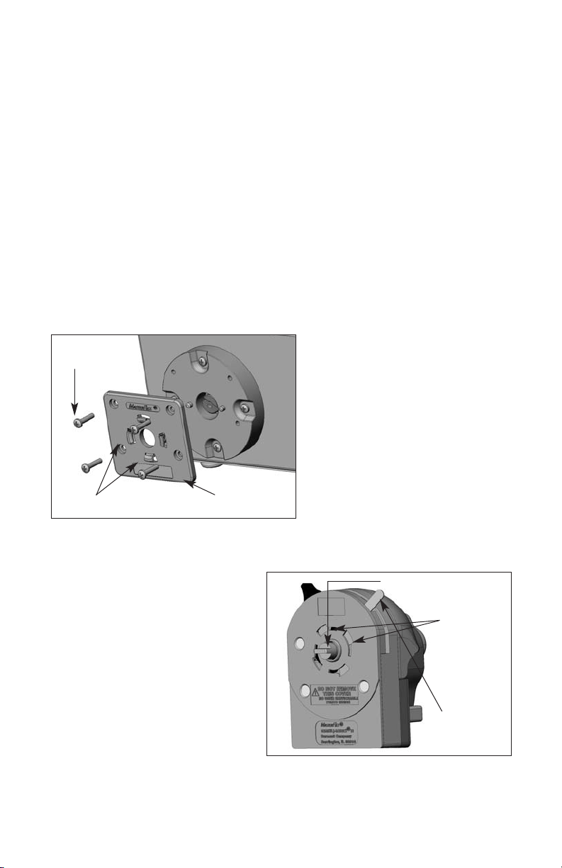
FIGURE 1
Attaching Mounting Plate to Drive
FIGURE 2
Back of EASY-LOAD 3 Pump
Pump Shaft with Tang
Bayonet
Features
Bayonet Lock
Lever-in Rear,
Locked Position
(4) screws
Bayonet Tabs
Mounting Plate
Page 5

INSTALLATION a nd REMOVAL
Attach the mounting plate to the MASTERFLEX drive, with the four Phillips head screws provided
in the mounting kit. (See Figure 1.) Orient the pump with its back facing the drive. Insert the tang
on the pump shaft into the slot in the shaft on the drive. Align the bayonet features on the pump
back with the bayonet tabs on the front of the mounting plate. (See Figures 1, 2 and 3.) The pump
should be tilted about 30 degrees counter-clockwise from the intended installed orientation.
Finally, press the pump firmly against the drive and rotate clockwise, until no more rotation is
possible (about 30 degrees). (See Figure 4.) The bayonet lock lever will snap toward the back
of the pump and automatically lock the pump to the mounting plate.
To remove the pump from the drive, pull the bayonet lock lever forward. Hold the lever forward
while rotating the pump as far counterclockwise as possible (approximately 30 degrees).
Then pull the pump away from the drive. The actuator lever should be in the far right position
when removing the pump. (See Figure 5.)
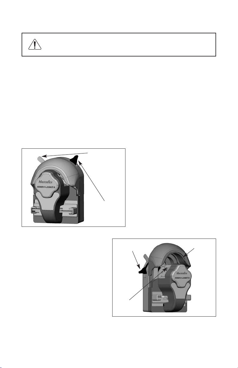
WARNING: Stop the drive before installing or removing
the pump from a drive
FIGURE 3
Position for Engaging Bayonet Feature
for Horizontal Mounting
FIGURE 4
Pump Bayonet Feature Locked
in Horizontal Pump Orientation
Approximately 30°
5
Page 6
TUBING LOADING a nd UN LOADING
To load tubing, open the pump by moving the actuator lever counterclockwise (left, if pump is
mounted vertically). (See Figures 5 and 6.) Insert a loop of tubing into one open tubing
retainer, between the occlusion bed and the rollers and into the other tubing retainer. (See
Figure 7.) Position the tubing so that it is firmly against the rollers and centered on the length
of the roller. While holding the tubing ends, move the actuator lever back to the far clockwise
(right) position, as shown in Figure 5. The pump will automatically grip the tubing. Tubing sizes
L/S
®
13, L/S®14, L/S®16, L/S®25, L/S®17 and L/S® 18 (thin wall) will automatically be
stretched by the pump. Approximately 5 pounds of force must be applied to the actuator lever
to fully close the pump and place the lever in its locked position (far right position) or to fully
open the pump (far left position). NOTE: It is not necessary to have an end of the tubing free to
load or unload tubing from the pump. A length of tubing, attached to other devices, may be
loaded into the pump, without disconnecting the tubing from adjacent devices.
WARNING: Stop the drive before installing or removing
tubing from the pump.
FIGURE 5
EASY-LOAD 3 Pump
in Fully Closed Position
FIGURE 6
EASY-LOAD 3 Pump
in Fully Open Position
Bayonet Lock
Lever-Pull
Forward
to Release
Actuator Lever-Far
Left Position
Actuator
Lever-Far
Right Position
Occlusion Bed
Roller
(one of 3 or 6)
6
Page 7

7
FIGURE 7
Tubing Path Through Pump—During Loading
Tubing
Retainer
(one per side)
To unload tubing from the pump, turn off the drive. Then open the pump by moving the
actuator lever counterclockwise (left), as described above. The pump will automatically open
the tubing retainers, as well as lifting the occlusion bed away from the tubing. Then pull the
tubing away from the pump front.
Occlusion
Bed
NOTE: When pump is not being used, store with actuator lever halfway between far left and
far right positions. (See figures 5 and 6.)
Page 8
8
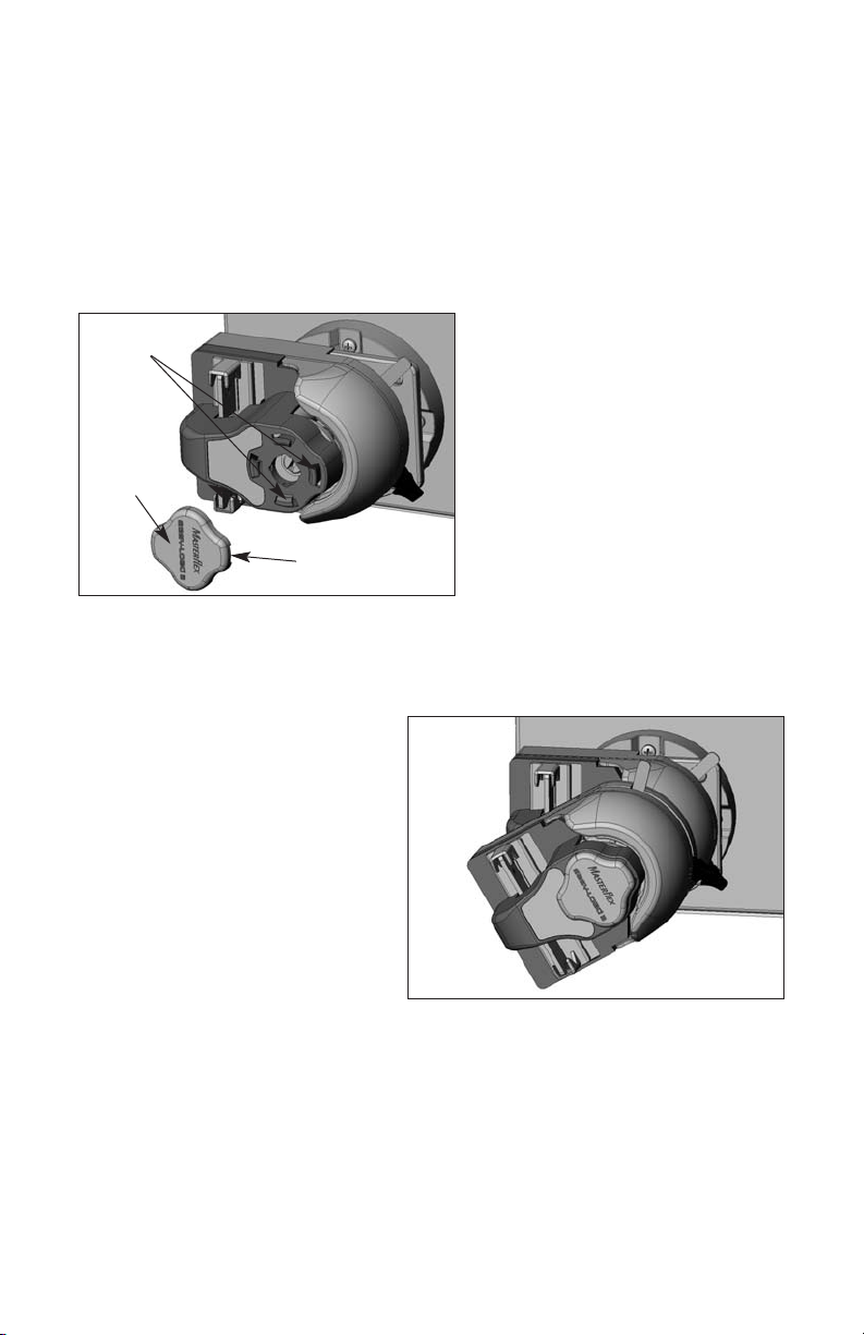
MULTI-C HANNEL MOUNTING
L/S EASY-LOAD 3 Pump Heads can be mounted in tandem (up to three), depending on the
torque capabilities of the drive. (See Figures 8, 9 and 10.) Once the mounting plate is
attached to a drive, no other mounting hardware is required. To use 4 pumps on one drive,
call dealer for recommendations.
To install a second pump, the cosmetic cover must be removed from the first pump.
Grasp the cover by the notches and pull it off. (See Figure 8.) Align the second pump
to the first, as if the first pump were a drive. Follow single pump mounting instructions
in ”INSTALLATION AND REMOVAL“. (See Figures 9 and 10.)
FIGURE 8
Preparation to Mount a Second Pump
Cosmetic
Cover
Notch (here and
on opposite edge)
Bayonet Tabs
on Pump Front
FIGURE 9
Engaging Bayonet Feature of Second
Pump to Bayonet Tabs on First Pump
Page 9

9
CAUTION:
Be sure that bayonet features on back of each
pump are fully engaged with bayonet tabs on
front of mounting plate or adjacent pump front
before operating pump. Bayonet lock lever
(see Figure 5) will snap back when bayonet
features engage completely.
NOTE: The tubing on the inside L/S EASY-LOAD 3 Pump Head(s)
can be changed without removing the outside Pump Head(s)
from the drive.
FIGURE 10
Drive with 2 Pumps Locked in Position
Page 10

10
MAINTENANCE AND CLEANING
■
No lubrication is required for the L/S EASY-LOAD 3 Pump Head.
■
Use a mild detergent solution or 70% isopropyl alcohol only to clean the Pump Head.
■
Do not immerse nor use excessive fluid.
■
This pump requires no maintenance, other than cleaning. There are no
user serviceable or replaceable parts inside.
REPLACEMENT PARTS AND ACCESSORIES
Mounting Plate Kit for L/S EASY-LOAD 3 Pump Heads: 77800-00
Kit contains (4) 8-32 screws and the mounting plate.
This kit adapts the EASY-LOAD 3 Pump Head to MASTERFLEX L/S pump drives.
Page 11

11
Printed in U.S.A.
WARRANTY
The Manufacturer warrants this product to be free from significant deviations from published specifications. If repair or adjustment is necessary
within the warranty period, the problem will be corrected at no charge if it
is not due to misuse or abuse on your part as determined by the
Manufacturer. Repair costs outside the warranty period, or those resulting
from product misuse or abuse, may be invoiced to you.
The warranty period for this product is two (2) years from the date of
purchase.
PRODUCT RETURN
To limit charges and delays, contact the seller or Manufacturer for authorization and shipping instructions before returning the product, either within or outside of the warranty period. When returning the product, please
state the reason for the return. For your protection, pack the product carefully and insure it against possible damage or loss. Any damages resulting
from improper packaging are your responsibility.
TECHNICAL ASSISTANCE
If you have any questions about the use of this product, contact the
Manufacturer or authorized seller.
Cole-Parmer
1-800-MASTERFLEX (627-8373) (U.S. and Canada only)
11 (847) 549-7600 (Outside U.S.)
(847) 549-7600 (Local)
www.masterflex.com
techinfo@coleparmer.com
Thermo Fisher Scientific
1-800-637-3739 (U.S. and Canada only)
11 (847) 381-7050 (Outside U.S.)
(847) 381-7050 (Local)
www.thermo.com
bar.barnant@thermofisher.com
 Loading...