

Page 1
WARRANTY
Use only MASTERFLEX® precision tubing with MASTERFLEX
pumps to ensure optimum performance. Use of other tubing may void
applicable warranties.
The Manufacturer warrants this product to be free from significant deviations
from published specifications. If repair or adjustment is necessary within
the warranty period, the problem will be corrected at no charge if it is not
due to misuse or abuse on your part as determined by the Manufacturer.
Repair costs outside the warranty period, or those resulting from product
misuse or abuse, may be invoiced to you.
The warranty period for this product is two (2) years from the date of
purchase.
®
PRODUCT RETURN
To limit charges and delays, contact the seller or Manufacturer for
authorization and shipping instructions before returning the product, either
within or outside of the warranty period. When returning the product,
please state the reason for the return. For your protection, pack the
product carefully and insure it against possible damage or loss. Any
damages resulting from improper packaging are your responsibility.
TECHNICAL ASSISTANCE
If you have any questions about the use of this product, contact the
Manufacturer or authorized seller.
OPERATING MANUAL
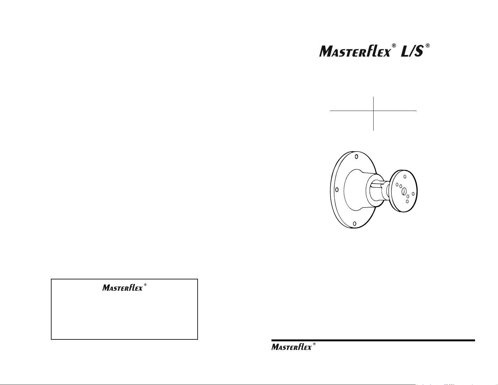
NEMA MOTOR-TO-PUMP
ADAPTERS
NEMA
Model No.
77495-00
77495-20
Gear Ratio
3.7:1
18.3:1
(US & Canada only) Toll Free 1-800-MASTERFLEX • 1-800-637-3739
(Outside US & Canada) 1-847-549-7600 • 1-847-381-7050
www.masterflex.com • techinfo@masterflex.com
*EN809 manufactured by:
Cole-Parmer Instrument Company
28W092 Commercial Avenue
Barrington, IL 60010
8
Printed in U.S.A.
A-1299-0412B
Edition 08
(US & Canada only) Toll Free: 1-800-MASTERFLEX • 1-800-637-3739
(Outside US & Canada) 1-847-549-7600 • 1-847-381-7050
www.masterex.com • techinfo@masterex.com
Page 2
WARNING: PRODUCT USE LIMITATION
!
This product is not designed for, nor intended for use in, patient
connected applications; including, but not limited to, medical and dental
use and, accordingly, has not been submitted for FDA approval.
NEMA
Model
No.
77495-00
77495-20
SPECIFICATIONS
Gear Ratio
3.7:1
18.3:1
Input Speed
(max)
2200 rpm
3600 rpm
Output Speed
(max)
600
200
DESCRIPTION
Series 77495 MOTOR-TO-PUMP ADAPTERS enable compatible
NEMA 56C motors to drive MASTERFLEX® L/S® Pump Heads. All
kinds of liquids can be delivered at desired flow rates. Each assembly
is composed of a planetary gear system in a rugged aluminum housing
with a mounting gasket, plus a motor shaft adapter.
Two Adapter models for NEMA motors with different gear ratios, are
available to obtain desired flow rates, depending upon motor speed,
Pump Head type, tubing size and material, plus backpressure conditions.
The Adapters are compatible with all MASTERFLEX® L/S® Pump Heads.
PUMP FOR LIQUIDS
ORIGINAL INSTRUCTIONS
Drive Mounting:
Pump Mounting:
Operating Temperature:
Storage Temperature Range:
Weight:
Dust/Water Resistance:
Torque Output:
Dimensions:
L × W × H
Humidity:
Altitude:
Compliance:
NEMA 56C
MASTERFLEX® L/S
32°F (0°C) to 122°F (50°C)
14°F (-10°C) to 149°F (65°C)
2 lbs (.9 kg)
IP56 with pump and motor mounted
70 oz-in (12 kg-cm) (3.7:1 Gear Ratio)
210 oz-in (15 kg-cm) (18.3:1 Gear Ratio)
5.75 in × 6.5 in × 6.5 in
(146 × 165 × 165 mm)
0-95%
Less than 2000 meters
(for CE mark)
EN809 (EU Machine Drive)
®
C-FLEX, NORPRENE, PHARMED, TYGON - Reg TM Saint-Gobain Performance Plastics Corp.
VITON - Reg TM E.I. duPont DeNemours & Co.
Trademarks bearing the ® symbol in this publication
are registered in the U.S. and other countries.
2
7
Page 3

(4) Mount the Adapter Housing
• Align the flat on the SHAFT ADAPTER with the mating “D” hole in
the GEAR mechanism.
Maintain the above alignment and carefully place the Adapter
flange against the face of the motor housing.
It may be necessary to turn the Adapter to obtain the proper pump
head orientation. This is because the tubing in some Pump Heads
exits from the top while tubing in others exits from the side. Also,
be sure to allow adequate space for operation of the tube loading
lever on the EASY-LOAD pumps.
(5) Install Adapter Bolts
• With all the components properly aligned, use the four bolts
provided to secure the Adapter assembly to the motor.
The last step is installation of the Pump Head. Refer to instructions
furnished with the Pump Head.
MAINTENANCE
Replaceable parts include the SHAFT ADAPTER, No. A-4103-CR and the
GASKET, No. A-3871, available through your Dealer.
Cleaning
Wash with mild detergent. Do not immerse nor use excessive fluid.
EQUIPMENT SELECTION
To obtain a proper match of system components for efficient operation,
an evaluation of the expected operating conditions should be made.
Motor loading is the most important factor. It determines whether one or
two Pump Heads can be used. Also, operating conditions, such as fluid
density, viscosity and temperature contribute to loading the pump in
varying degrees. Backpressure, tubing size and material are additional
factors. Tubing materials like TYGON®, NORPRENE®, PHARMED
and VITON® fluoroelastomer increase the load more than silicone and
C-FLEX® tubing. Even motor temperature and voltage may have an
effect on load capabilities.
Keep these considerations in mind when selecting motor horsepower
or torque. Sometimes it may be necessary to compensate for difficult
or unusual operating conditions. Refer to your motor specifications for
details.
The procedure for teaming-up an Adapter with the appropriate motor and
pump head is very straightforward:
(1) Verify Required Flow Rate
• Table 1 shows flow rates for individual Adapters and standard
tubings.
Use only MASTERFLEX ® Precision tubing with MASTERFLEX ®
Pumps to ensure optimum performance. Use of other tubing may
void applicable warranties.
®
BPT
Table 1
Flow rates* for NEMA (77495-00)
Adapter models in mL/min
Tubing
L/S® 13
L/S® 14
L/S® 16
L/S® 15, L/S® 25
L/S® 17, L/S® 24
L/S® 18, L/S® 35
L/S® 36
6
900 1100 1440 1725 2200
15
51 63
200 310 380 480
410 510 660 800 1000
680 840 1100 1300 1700
930 1150 1500 1800 2300
1200 1450 1900 2300 2900
Motor Speed in rpm
18 23 30 36
82 100 130
240
3
Page 4

Flow rates* for NEMA (77495-20)
Adapter models in mL/min
Tubing
L/S® 13
L/S® 14
L/S® 16
L/S® 15, L/S® 25
L/S® 17, L/S® 24
L/S® 18, L/S® 35
L/S® 36
*
Flow rates for L/S Standard, EASY-LOAD®, EASY-LOAD II®, EASY-LOAD
900
3.0
10
39
83
140
190
240
Motor Speed in rpm
1100
3.6
13
48
100
170
230
290
1440
130
220
300
380
4.7
17
63
1725
6
20
75
160
270
360
460
2900
9.5
33
130
270
450
600
760
3450
12
40
150
320
540
720
920
3® and 3-roller cartridge Pump Heads. High performance Pump Head
flow rates will be slightly higher.
Be sure the Adapter to be installed will accommodate the intended range
of pumping applications.
(2) Select Motor
• The specifications section shows motor speed capacities for
individual Adapters. Besides having the proper mounting face,
the motor to be used must not exceed the speeds indicated.
In no case will a motor H.P. greater than 1/4 be required for the
Pump Heads compatible with these Adapters.
Table 2 shows the volume per pump revolution for specific tubing
numbers. Use Tables 1 and 2 as guides in selecting the proper
tubing for the required flow rate.
Table 2
Tubing
L/S® 13
L/S® 14
L/S® 16
L/S® 15, L/S® 25
L/S® 17, L/S® 24
L/S® 18, L/S® 35
L/S® 36
(3) Select a Compatible Pump Head
• The Adapters are compatible with all L/S Pump Heads. Pump
Head selection is based primarily on required flow rates using a
specific tubing (see Tables 1 and 2).
Volume per pump Revolution
(mL)
0.06
0.21
0.80
1.7
2.8
3.8
4.8
INSTALLATION
The Adapter can be installed between the selected motor and Pump Head
in just a few minutes. First, check the motor manufacturer’s specifications
t
o ensure that the motor meets the NEMA 56C face mounting requirements.
Then proceed with these steps:
(1) Mount the Motor Drive
• Select a site and mounting surface appropriate for the pumping
operations. Refer to the motor manufacturer’s instructions.
(2) Install the Shaft Adapter
• Figure 1 shows the proper alignment of all components:
MOTOR
MOUNTING
FLANGE
GASKET
MOTOR
SHAFT
ADAPTER
Figure 1: Adapter components aligned with a drive motor and Pump Head.
D
SHAFT
MATING
D HOLE
IN GEAR
• Mount the SHAFT ADAPTER fully onto the motor drive shaft.
• Tighten the two SET SCREWS. Use the Allen wrench provided. If
the motor shaft has a flat, be sure that one of the SET SCREWS is
tightened against it.
(3) Mount the Gasket
• Place the GASKET over the motor face, as shown in the drawing.
ALLEN
WRENCH
SET SCREWS (2)
PUMP HEAD
MOUNTING
PLATE
ADAPTER
MOUNTING
BOLTS (4)
TO
PUMP
HEAD
4
5
 Loading...