

Page 1
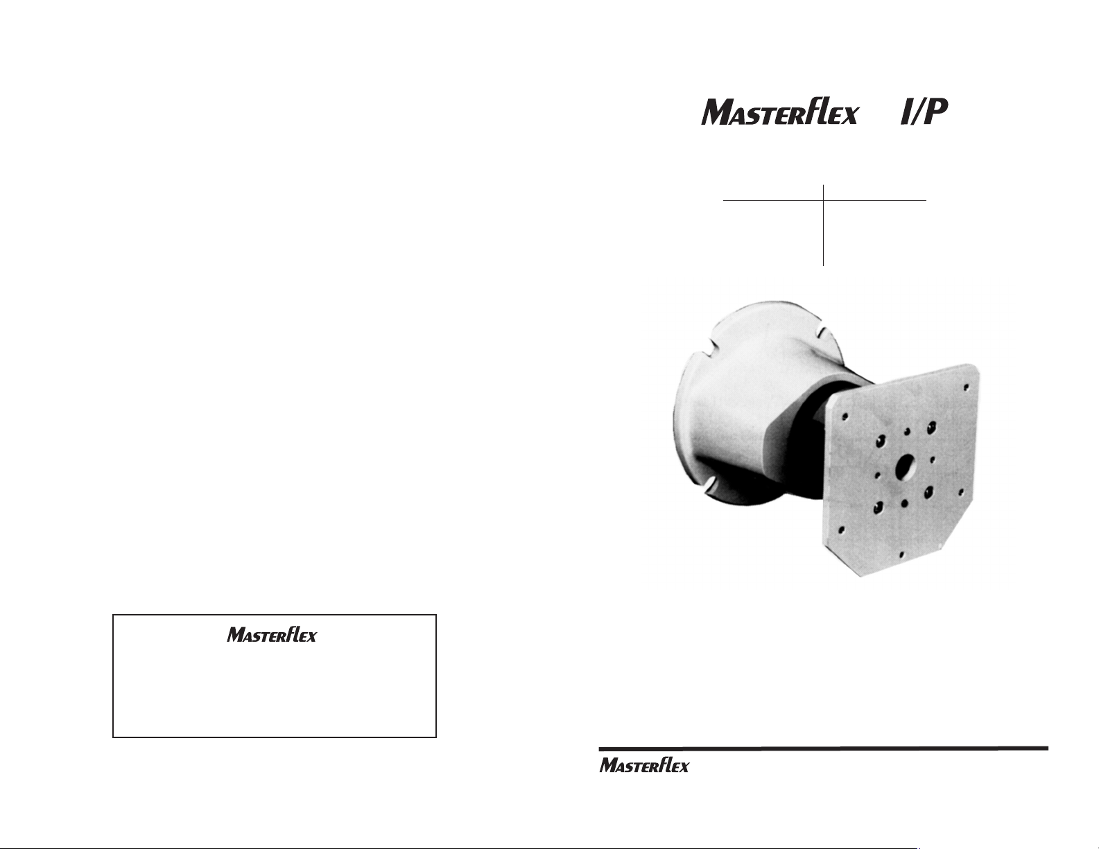
OPERATING MANUAL
NEMA 56C MOTOR-TO-PUMP
ADAPTER
®
®
Model No.
77490-00
77490-10
77490-20
77490-30
Gear Ratio
3.1:1
4.8:1
9.7:1
17.8:1
A-1299-0347B
Edition 09
(US & Canada only) Toll Free 1-800-MASTERFLEX ● 1-800-637-3739
(Outside US & Canada) 1-847-549-7600 ● 1-847-381-7050
www.masterflex.com ● techinfo@masterflex.com
®
Printed in U.S.A.
(US & Canada only) Toll Free 1-800-MASTERFLEX • 1-800-637-3739
(Outside US & Canada) 1-847-549-7600 • 1-847-381-7050
www.masterflex.com • techinfo@masterflex.com
*EN809 manufactured by:
Cole-Parmer Instrument Company
28W092 Commercial Avenue
Barrington, IL 60010
®
Page 2

WARRANTY
Use only MASTERFLEX precision tubing with MASTERFLEX pumps
to ensure optimum performance. Use of other tubing may void applicable warranties.
The Manufacturer warrants this product to be free from significant deviations from published specifications. If repair or adjustment is necessary
within the warranty period, the problem will be corrected at no charge if it
is not due to misuse or abuse on your part as determined by the
Manufacturer. Repair costs outside the warranty period, or those resulting
from product misuse or abuse, may be invoiced to you.
The warranty period for this product is two (2) years from the date of
purchase.
PRODUCT RETURN
To limit charges and delays, contact the seller or Manufacturer for authorization and shipping instructions before returning the product, either within or outside of the warranty period. When returning the product, please
state the reason for the return. For your protection, pack the product carefully and insure it against possible damage or loss. Any damages resulting
from improper packaging are your responsibility.
TECHNICAL ASSISTANCE
If you have any questions about the use of this product, contact the
Manufacturer or authorized seller.
Title Page
DESCRIPTION. . . . . . . . . . . . . . . . . . . . . . . . . . . . . . . . . . . . . . . . . . . . . 2
APPLICATION DATA . . . . . . . . . . . . . . . . . . . . . . . . . . . . . . . . . . . . . . . . 2
EQUIPMENT SELECTION . . . . . . . . . . . . . . . . . . . . . . . . . . . . . . . . . . . 3
(1) Verify Required Flow Rates . . . . . . . . . . . . . . . . . . . . . . . . . . . . . . . . 3
(2) Select Motor . . . . . . . . . . . . . . . . . . . . . . . . . . . . . . . . . . . . . . . . . . . . 3
(3) Select a Compatible Pump Head . . . . . . . . . . . . . . . . . . . . . . . . . . . . 4
(4) Optional Tandem Operation . . . . . . . . . . . . . . . . . . . . . . . . . . . . . . . . 4
INSTALLATION . . . . . . . . . . . . . . . . . . . . . . . . . . . . . . . . . . . . . . . . . . . . 5
(1) Mount the Motor Drive . . . . . . . . . . . . . . . . . . . . . . . . . . . . . . . . . . . . 5
(2) Install the Shaft Adapter . . . . . . . . . . . . . . . . . . . . . . . . . . . . . . . . . . . 5
(3) Mount the Gasket . . . . . . . . . . . . . . . . . . . . . . . . . . . . . . . . . . . . . . . . 6
(4) Mount the Adapter Housing . . . . . . . . . . . . . . . . . . . . . . . . . . . . . . . . 6
(5) Install Adapter Bolts . . . . . . . . . . . . . . . . . . . . . . . . . . . . . . . . . . . . . . 6
MAINTENANCE. . . . . . . . . . . . . . . . . . . . . . . . . . . . . . . . . . . . . . . . . . . . 6
SPECIFICATIONS . . . . . . . . . . . . . . . . . . . . . . . . . . . . . . . . . . . . . . . . . . 7
WARRANTY. . . . . . . . . . . . . . . . . . . . . . . . . . . . . . . . . . . . . . . . . . . . . . . 8
PRODUCT RETURN . . . . . . . . . . . . . . . . . . . . . . . . . . . . . . . . . . . . . . . . 8
TECHNICAL ASSISTANCE . . . . . . . . . . . . . . . . . . . . . . . . . . . . . . . . . . . 8
8
TABLE OF CONTENTS
Page 3

7
Cleaning
Wash with mild detergent. Do not immerse nor use excessive fluid.
SPECIFICATIONS
Series 77490 Adapter
Drive Mounting: NEMA 56C
Pump Mounting: MASTERFLEX I/P Short-Shaft
Operating Temperature: 32°F (0°C) to 104°F (40°C)
Storage Temperature Range: 14°F (-10°C) to 149°F (65°C)
Weight: 4 lbs (1.8 kg)
Dust/Water Resistance: IP34 with pump and
motor mounted
Dimensions: 5 3/4 in × 6 1/2 in × 6 1/2 in
L × W × H: (146 x 165 × 165 mm)
Humidity: 0-95%
Altitude: Less than 2000 meters
DESCRIPTION
Series 77490 MOTOR-TO-PUMP ADAPTERS enable compatible NEMA
56C motors to drive peristaltic pumps. All kinds of liquids can be delivered
at desired flow rates. Each assembly is composed of a planetary gear
system in a rugged aluminum housing with a mounting gasket, plus a
motor shaft adapter.
Four Adapter models, each with different gear ratios, are available to obtain
desired flow rates, depending upon motor speed, Pump Head type, tubing
size and material, plus backpressure conditions.
The Adapters are compatible with all MASTERFLEX®I/P® Standard,
EASY-LOAD®and High Performance short-shaft Pump Heads.
APPLICATION DATA
To obtain a proper match of system components for efficient operation, an
evaluation of the expected operating conditions should be made. Motor
loading is the most important factor. It determines whether one or two
Pump Heads can be used. Also, operating conditions, such as fluid density, viscosity and temperature, contribute to loading the pump in varying
degrees. Backpressure, tubing size and material are additional factors.
Tubing materials like TYGON®, NORPRENE®, PHARMED®BPT and
VITON®(fluoroelastomer) increase the load more than silicone and
C-FLEX®tubing. Even motor temperature and voltage may have an effect
on load capabilities.
Keep these considerations in mind when selecting motor horsepower or
torque. Sometimes it may be necessary to compensate for difficult or
unusual operating conditions. Refer to your motor specifications for details.
C-FLEX, PHARMED, NORPRENE, TYGON - Reg TM Saint-Gobain Performance Plastics Corp.
VITON - Reg TM E.I. DuPont de Nemours and Co.
Trademarks bearing the ® symbol in this publication
are registered in the U.S. and in other countries.
2
Model Gear Ratio Input Speed Output Speed Output Torque
No. (max.) (max.) (max.)
oz-in kg-cm
77490-00 3.1:1 2015 rpm 650 864 62
77490-10 4.8:1 3120 rpm 650 864 62
77490-20 9.7:1 3600 rpm 370 640 46
77490-30 17.8:1 4800 rpm 270 760 55
WARNING: PRODUCT USE LIMITATION
This product is not designed for, nor intended for use in, patient
connected applications; including, but not limited to, medical and
dental use and, accordingly, has not been submitted for FDA approval.
Page 4

EQUIPMENT SELECTION
The procedure for teaming-up a 77490 Adapter with the appropriate motor
and Pump Head is very straightforward:
(1) Verify Required Flow Rates
Table 1 shows maximum flow rates for individual 77490 Adapters and
standard tubings.
Use only MASTERFLEX®Precision tubing with MASTERFLEX
Pumps to ensure optimum performance. Use of other tubing may
void applicable warranties.
Be sure the Adapter to be installed will accommodate the intended range
of pumping applications.
Table 1
*These speeds may be increased slightly under light loads, i.e., low pressure pumping with
silicone or C-FLEX tubing.
(2) Select Motor
Table 1 also shows motor speed capacities for individual Adapters.
Besides having a NEMA 56C mounting face, the motor to be used must
not exceed the speeds indicated.
For general guidance in determining motor size, 1/5 horsepower is
required to pump water at 2 GPM through a single I/P®73 MASTERFLEX
tube at 30 psig (0 psig, for two I/P®73 tubes). In no case will a motor hp
greater than 1/2 be required for the Pump Heads compatible with the
Series 77490 Adapters.
Note: Tubing numbers shown refer to the last two digits of the tubing
catalog number. For example, silicone tubing catalog number is 96410-73
,
thus the tubing number in this manual is referred to as simply I/P®73.
Table 2 shows the volume per pump revolution for specific tubing numbers.
Use Tables 1 and 2 as a guide in selecting the proper tubing for the
required flow rate.
3
(3) Mount the Gasket
■ Place the GASKET over the 56C motor face, as shown in the
drawing.
(4) Mount the Adapter Housing
■ To minimize noise and maximize planetary gear longevity, the
optimum procedure recommended for assembly of the Adapter
Housing to the 56C Motor Housing is to set up vertically (motor
shaft up) per installation sketch on previous page.
■ Align the flat on the SHAFT ADAPTER with the mating “D” hole in
the GEAR mechanism.
■ Maintain the above alignment and carefully place the Adapter
flange against the face of the 56C motor housing.
■ It may be necessary to turn the Adapter to obtain the proper Pump
Head orientation. This is necessary because the tubing in the I/P
Standard Pump Heads exits from the top, and tubing in the I/P
EASY-LOAD exits from the side. Also, be sure to allow adequate
space for operation of the tube loading lever on the EASY-LOAD
pumps.
(5) Install Adapter Bolts
■
With all the components properly aligned, use the four 3/8 in BOLTS
provided to secure the Adapter assembly to the motor.
■ Use the proper procedure for tightening the four bolt flange, i.e.,
number the BOLTS 1 thru 4 in a CW or CCW direction. Tighten
gradually and alternately 1 & 3 then 2 & 4. Final torque to be
16.5/19.5 (ft-lb). If feasible, (while in this position) run or jog motor
slowly and listen for any objectionable gear noise. If noisy, loosen
bolts, turn adapter shaft or slowly jog motor, then retighten bolts as
above.
The last step is installation of the Pump Head to the PUMP HEAD
MOUNTING PLATE. Refer to instructions furnished with the Pump Head.
For maximum life, install the pump housing using the two 1.0 inch cap
head screws supplied with the pump.
MAINTENANCE
While there are no serviceable parts, replaceable parts include the SHAFT
ADAPTER (No. A-3870) and the GASKET (No. A-3871), available through
your dealer.
6
Max. Flow Rate for Tubing No. Max.
Adapter I/P®26 I/P®73 I/P®82 Gear Motor
No. GPM LPM GPM LPM GPM LPM Ratio Speed
(rpm)
77490-00 1 4 2.1 8 3.5 13.1 3.1:1 2015
77490-10 1 4 2.1 8 3.5 13.1 4.8:1 3120
77490-20 0.6 2.2 1.2 4.4 2 7.5 9.7:1 3600*
77490-30 0.4 1.6 0.75 2.9 1.4 5.4 17.8:1 4800*
Page 5

INSTALLATION
The 77490 Adapters can be installed between the selected motor and
Pump Head in just a few minutes. First, check the motor manufacturer’s
specifications to ensure that the motor meets the NEMA 56C mounting
requirements. Then proceed with these steps:
(1) Mount the Motor Drive
■ Select a site and mounting surface appropriate for the pumping
operations. Refer to the motor manufacturer’s instructions.
(2) Install the Shaft Adapter
■ The following drawing shows the proper alignment of all
components.
Series 77490 Adapter components aligned with a drive motor and Pump Head.
■ Mount the SHAFT ADAPTER on the 56C MOTOR drive shaft.
■ Tighten the two SETSCREWS. Use the 5/16 in Allen wrench
provided. If the motor shaft has a flat, be sure that one of the SET
SCREWS is tightened against it.
5
Table 2
(3) Select a Compatible Pump Head
Series 77490 Adapters are compatible with all MASTERFLEX I/P
Standard, EASY-LOAD and High Performance short-shaft Pump Heads.
(4) Optional Tandem Operation
A single motor can drive up to two Pump Heads.
With the proper system components selected, the next step is installation.
4
I/P®Tubing Volume Per Pump Revolution
No. Gallons Liters
26 0.0016 0.0060
73 0.0032 0.012
82 0.0054 0.020
TO PUMP
HEAD
SHAFT
ADAPTER
D
SHAFT
MATING
D HOLE
IN GEAR
PUMP HEAD
MOUNTING
PLATE
ALLEN
WRENCH
GASKET
56C MOTOR
MOUNTING
FLANGE
MOTOR
SETSCREWS (2)
3/8 IN
MOUNTING
BOLTS (4)
ADAPTER
MOUNTING
FLANGE
 Loading...