

Page 1
®
OPERATING MANUAL:
PUMP DRIVES
MODE DʼEMPLOI:
ENTRAÎNEMENTS
DE POMPES
BETRIEBSANLEITUNG:
PUMPENANTRIEBE
MANUAL DE FUNCIONAMIENTO:
MOTOR DE BOMBAS
MANUALE DI ISTRUZIONI:
UNITÀ DI
CONTROLLO POMPA
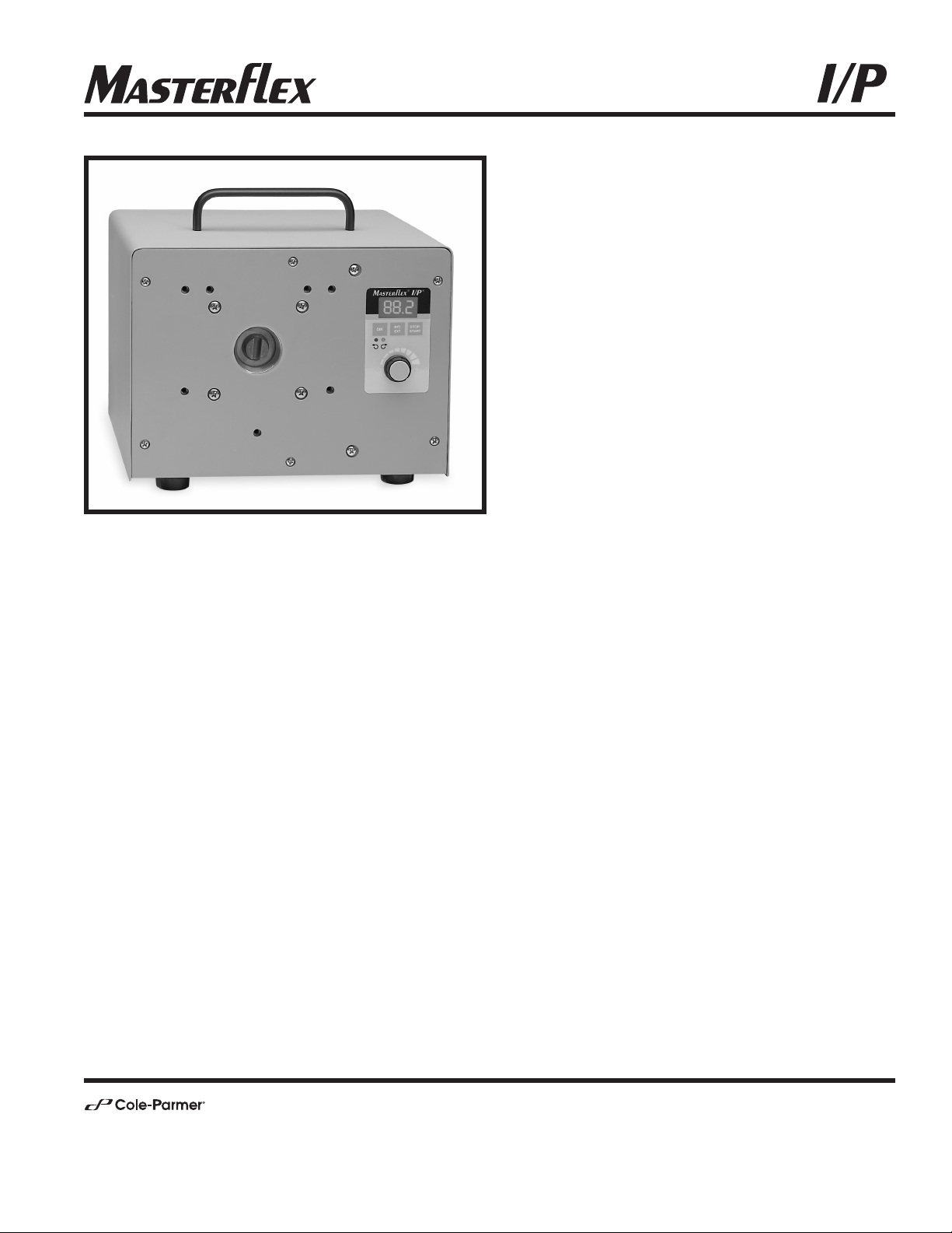
77411-00 pump drive
Model Nos.
N° de modèle
Modellnummer
Número de modelo
Modello nº
77410-10
77411-00
®
®
A-1299-1037B
Edition 06
(US & Canada only) Toll Free 1-800-MASTERFLEX • 1-800-637-3739
(Outside US & Canada) 1-847-549-7600 • 1-847-381-7050
E-mail: techinfo@coleparmer.com
www.masterflex.com • www.coleparmer.com
Page 2
TABLE OF CONTENTS
Title
SAFETY PRECAUTIONS . . . . . . . . . . . . . . . . . . . . . . . . . . . . . . . . . . . . . . . . . . . . . . . . . . . . . . . . . . . . . . . . . . . . . . . .2
INTRODUCTION
. . . . . . . . . . . . . . . . . . . . . . . . . . . . . . . . . . . . . . . . . . . . . . . . . . . . . . . . . . . . . . . . . . . . . . . . . . . . . . . . . .3
CONTROL/DISPLAY FUNCTIONS
. . . . . . . . . . . . . . . . . . . . . . . . . . . . . . . . . . . . . . . . . . . . . . . . . . . . . . . . . . . . .3
SETUP AND DRIVE OPERATION
. . . . . . . . . . . . . . . . . . . . . . . . . . . . . . . . . . . . . . . . . . . . . . . . . . . . . . . . . . . . . .4
Automatic Start Enable/Disable . . . . . . . . . . . . . . . . . . . . . . . . . . . . . . . . . . . . . . . . . . . . . . . . . . . . . . . . . . . . . . . . .4
REMOTE CONTROL . . . . . . . . . . . . . . . . . . . . . . . . . . . . . . . . . . . . . . . . . . . . . . . . . . . . . . . . . . . . . . . . . . . . . . . . . . . . . .5
Remote Control Setup . . . . . . . . . . . . . . . . . . . . . . . . . . . . . . . . . . . . . . . . . . . . . . . . . . . . . . . . . . . . . . . . . . . . . . . . . . .5
Internal / External Operation
. . . . . . . . . . . . . . . . . . . . . . . . . . . . . . . . . . . . . . . . . . . . . . . . . . . . . . . . . . . . . . . . . . . .5
TROUBLESHOOTING AND MAINTENANCE . . . . . . . . . . . . . . . . . . . . . . . . . . . . . . . . . . . . . . . . . . . . . . . . .7
Fuse Replacement . . . . . . . . . . . . . . . . . . . . . . . . . . . . . . . . . . . . . . . . . . . . . . . . . . . . . . . . . . . . . . . . . . . . . . . . . . . . . .7
Troubleshooting
. . . . . . . . . . . . . . . . . . . . . . . . . . . . . . . . . . . . . . . . . . . . . . . . . . . . . . . . . . . . . . . . . . . . . . . . . . . . . . . . . .7
Cleaning
. . . . . . . . . . . . . . . . . . . . . . . . . . . . . . . . . . . . . . . . . . . . . . . . . . . . . . . . . . . . . . . . . . . . . . . . . . . . . . . . . . . . . . . . .8
Replacement Parts and Accessories
. . . . . . . . . . . . . . . . . . . . . . . . . . . . . . . . . . . . . . . . . . . . . . . . . . . . . . . . . . .8
SPECIFICATIONS . . . . . . . . . . . . . . . . . . . . . . . . . . . . . . . . . . . . . . . . . . . . . . . . . . . . . . . . . . . . . . . . . . . . . . . . . . . . . . . . 9
TECHNICAL ASSISTANCE
. . . . . . . . . . . . . . . . . . . . . . . . . . . . . . . . . . . . . . . . . . . . . . . . . . . . . . . . . . . . . . . . . . . . .10
SAFETY PRECAUTIONS
WARNINGS: No user serviceable parts inside. Do not remove covers.
Refer servicing to your dealer.
Tubing breakage may result in fluid being sprayed from pump.
Use appropriate measures to protect operator and equipment.
Turn drive off before removing or installing tubing. Fingers or
loose clothing could get caught in drive mechanism.
To avoid electrical shock, the power cord protective grounding
conductor must be connected to ground. Not for operation in
wet locations as defined by EN 61010-1.
CAUTIONS: Do not stack drives. Keep 3" minimum distance around
and above drive for proper cooling.
2
®
®
WARNING: PRODUCT USE LIMITATION
This product is not designed for, nor intended for use in, patientconnected applications, including, but not limited to, medical and dental
use, and, accordingly, has not been submitted for FDA approval. If drive
is used in a manner not specified in this manual the protection provided
by the equipment may be impaired.
Trademarks bearing the ® symbol in this publication are registered in the U.S. and in other countries.
Page 3

3
®
®
INTRODUCTION
The brushless drive controls the speed of MASTERFLEX I/P Pump Heads to provide variable flow rates
from 0.2 to 17 L/min (0.06 to 4.5 gallons/min). Achieve up to 26 LPM (7 GPM) with two stacked Standard
or EASY-LOAD I/P Pump Heads. One MASTERFLEX High-Performance I/P Pump Head may be driven.
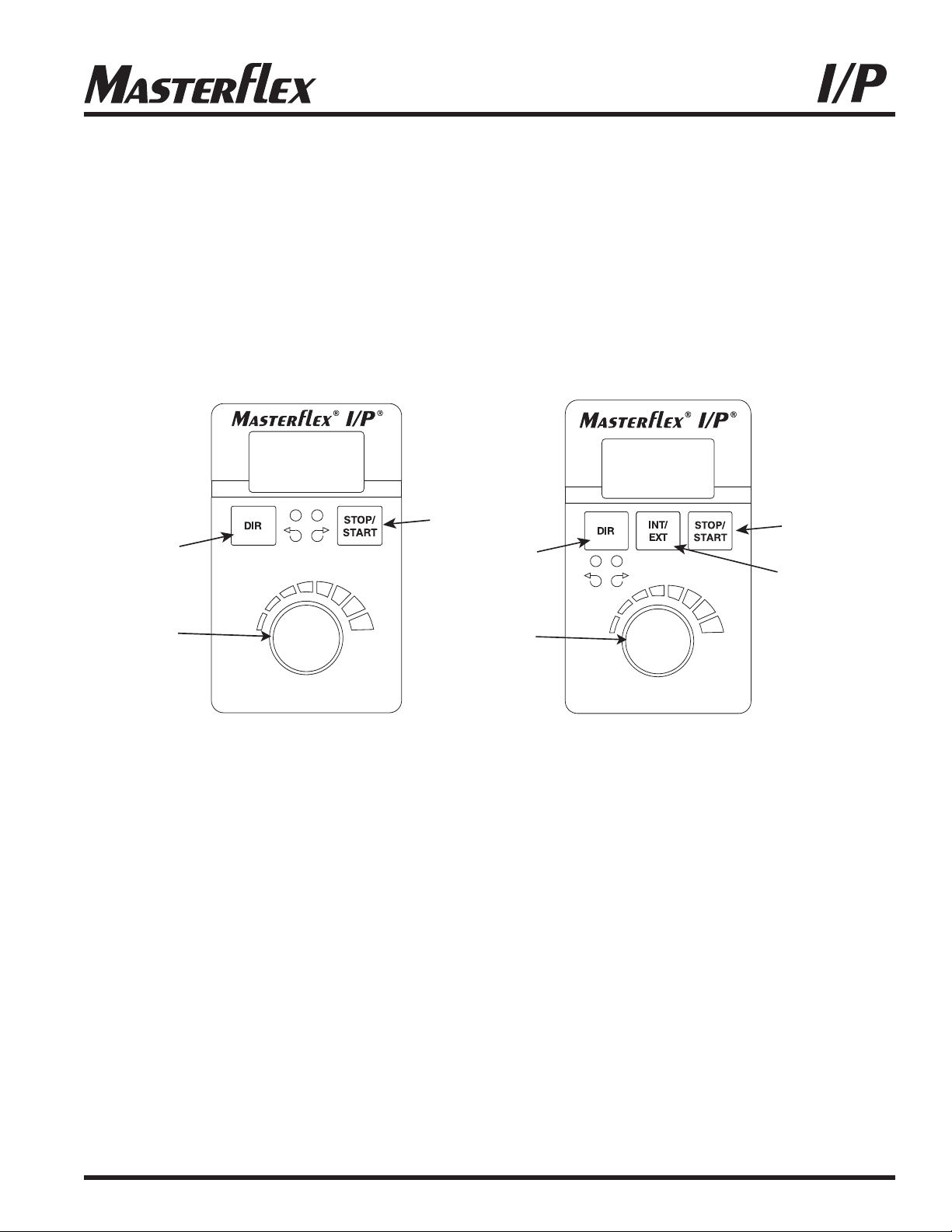
CONTROL/DISPLAY FUNCTIONS
Press keys to activate function.
A
B
C
A
D
B
C
A. STOP/START—Start/Stop pump.
B. DIRECTION—To change motor direction.
C. SPEED—Selects output speed from 5 to 100% Full Scale (33 to 650 RPM). Clockwise rotation increases speed.
D. INT/EXT—(Model 77411-00 only) INT for internal control; EXT for remote current or voltage control.
77410-10
Figure 1
77411-00
Page 4
4
®
®
Speed Setting I/P 26 I/P 73 I/P 82 I/P 70 I/P 88 I/P 89
10%
0.4 LPM 0.8 GPM 1.3 LPM 0.8 LPM 1.3 LPM 1.7 LPM
0.11 GPM 0.21 GPM 0.35 GPM 0.21 GPM 0.35 GPM 0.45 GPM
20%
0.8 LPM 1.6 LPM 2.6 LPM 1.6 LPM 2.6 LPM 3.4 LPM
0.22 GPM 0.42 GPM 0.70 GPM 0.42 GPM 0.70 GPM 0.90 GPM
30%
1.2 LPM 2.4 LPM 3.9 LPM 2.4 LPM 3.9 LPM 5.1 LPM
0.33 GPM 0.63 GPM 1.05 GPM 0.63 GPM 1.05 GPM 1.35 GPM
40%
1.6 LPM 3.2 LPM 5.2 LPM 3.2 LPM 5.2 LPM 6.8 LPM
0.44 GPM 0.84 GPM 1.40 GPM 0.84 GPM 1.40 GPM 1.80 GPM
50%
2.0 LPM 4.0 LPM 6.5 LPM 4.0 LPM 6.5 LPM 8.5 LPM
0.55 GPM 1.05 GPM 1.75 GPM 1.05 GPM 1.75 GPM 2.25 GPM
60%
2.4 LPM 4.8 LPM 7.8 LPM 4.8 LPM 7.8 LPM 10 LPM
0.66 GPM 1.26 GPM 2.1 GPM 1.26 GPM 2.1 GPM 2.70 GPM
70%
2.8 LPM 5.6 LPM 9.1 LPM 5.6 LPM 9.1 LPM 12 LPM
0.77 GPM 1.47 GPM 2.45 GPM 1.47 GPM 2.45 GPM 3.15 GPM
80%
3.2 LPM 6.4 LPM 10 LPM 6.4 LPM 10 LPM 14 LPM
0.88 GPM 1.68 GPM 2.8 GPM 1.68 GPM 2.8 GPM 3.60 GPM
90%
3.6 LPM 7.2 LPM 12 LPM 7.2 LPM 12 LPM 15 LPM
0.99 GPM 1.89 GPM 3.15 GPM 1.89 GPM 3.15 GPM 4.05 GPM
100%
4 LPM 8 LPM 13 LPM 8 LPM 13 LPM 17 LPM
1.1 GPM 2.1 GPM 3.5 GPM 2.1 GPM 3.5 GPM 4.5 GPM
AUTOMATIC START ON/OFF (Internal mode only)
Press and hold DIR on power-up. After five (5) seconds, display will read “ON” (factory default) or “OFF”. Hold the
DIR key for an additional 3 seconds and the display will toggle to the other option every 3 seconds. Release the DIR
key when the desired mode is being displayed. After releasing the key, “ON” or “OFF” will remain displayed
for about 3 seconds and then the normal power-on sequence will begin. When “ON” is selected, drive will start automatically at power-up if it was running when powered down.
SETUP AND DRIVE OPERATION
1. Attach any external control connections. (Model 77411-00 only)
2. Mount Pump Head and load tubing (see Pump Head manual).
NOTE: The High-Performance I/P pump is mounted with the tubing to the left. The Standard I/P pump is mounted
with the tubing up. The EASY-LOAD I/P pump is mounted with the occlusion bed up.
3. Turn drive on.
4. Select INTernal or EXTernal operation. (Model 77411-00 only)
5. Select pump DIRection (clockwise or counter-clockwise).
6. Press STOP/START key to begin pumping.
7. Adjust speed (listed flow rates are for reference only. Flow will vary with pressure, tubing, viscosity, and time):
NOTE: While in INTernal mode, drive will automatically restart after a brownout or power out condition unless
operator changes default setting. If speed is being controlled by an external signal, drive will automatically
restart with a non-zero speed command.
Page 5

5
®
®
REMOTE CONTROL (Model 77411-00 only)
l
Selectable input (4–20 mA, 0–10V DC )
l
±0.5% linearity control
l
±50V common mode range with respect to earth ground
l
Internal & External START/STOP; External CW/CCW via contact closure
REMOTE CONTROL SETUP
1. Place the power switch in the off position.
2. Connect the cable from the external remote control to the mating receptacle on the rear panel.
3. Select operation from front panel potentiometer, external 4-20mA current source, or external
0-10 V voltage source as follows:
a. Press and hold the INT/EXT control for approximately 5 seconds until the present
setting of the speed source is displayed.
b. Continuing to hold the INT/EXT control will cause the display to cycle through the three choices:
“4.20” indicating the 4-20 mA input, “0.10" indicating the 0-10 V input, or “Pot” indicating that the
Speed Input Potentiometer will be used. When the key is released, the programmed choice will
remain on the display for approximately 3 seconds as confirmation of the speed source choice
made before returning to normal operation.
4. To adjust the voltage or current scaling for other than zero to full scale:
a. Press and hold the INT/EXT control (approximately 5 seconds) until the external speed
source is displayed. (“4.20”, “0.10”, or “Pot”)
b. Release the INT/EXT control and press the DIR control before the external speed
source disappears from the display.
c. The display will show “Lo” for about 3 seconds and then flash the current speed setting for the low set
point (4 mA or 0 V). To change this setting, adjust the Speed Control Potentiometer to the percent of full
speed desired. To make no change, press the DIR control a second time.
d. After pressing the DIR control the second time, the display will show “Hi” and then flash
the high (20 mA or 10 V) speed set point. This can be changed by adjusting the Speed
Control Potentiometer, or left as is by pressing the DIR control again.
e. The third press of the DIR control returns the drive to normal operation.
NOTE: The 4-20 mA input, the 0-10 V input, and the 4-20 mA output are not scaled separately.
INTernal / EXTernal Operation
1. The EXTernal mode of operation enables the PUMP READY output, the EXTERNAL START/STOP, EXTERNAL
CW/CCW, 4-20 mA, and 0-10 V inputs, while disabling the INTERNAL START/STOP input (e.g. footswitch) and
front-panel DIR and START controls. The pump speed is determined by the programmed choice of 4-20 mA,
0-10 V, or front panel potentiometer inputs. The front panel STOP/START control overrides the EXTERNAL
START/STOP input to stop the drive.
2. In the INTernal mode of operation, either the INTERNAL START/STOP input (e.g. footswitch) or the front panel
STOP/START control can start or stop the drive at the speed set by the front-panel SPEED POT.
Page 6
6
®
®
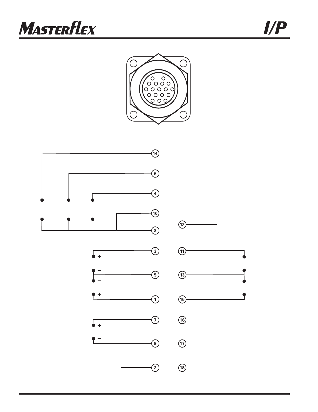
12
3456
78910
12 13 14 15
16 17 18
11
RED/YELLOW
BLUE
GREEN
GREY
YELLOW
WHITE
ORANGE
3
BLACK
BROWN
VIOLET
N.C.
N.C.
PINK
RED/GREEN
RED/BLACK
PUMP READY
N.O. CONTACT
EXTERNAL
START/STOP
EXTERNAL
CW/CCW
INTERNAL
START/STOP
RED
(RESERVED)
N.C.
TAN
(RESERVED)
+++
–––
OUTPUT
4-20mA
INPUT
0-10V
INPUT
4-20mA
NOTE: Colors are those of Remote Cable.
Catalog number 77300-32
PUMP READY
N.C. CONTACT
Figure 2
Page 7
7
®
®
TROUBLESHOOTING AND MAINTENANCE
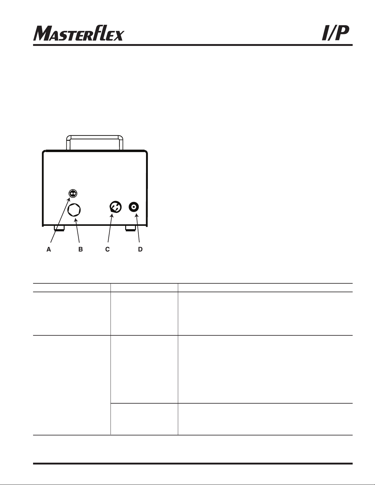
FUSE REPLACEMENT
1 Place the power switch in the off position.
2 Disconnect the AC power input line cord from the attached line and receptacle.
3 Remove and check the fuse and replace if defective
4 Reconnect the AC power input line cord to the receptacle.
Figure 3
A. T6.3A Fuse (CAUTION: Do not substitute.)
B. External receptacle for remote control
C. IEC 320 Power cord
D. Power switch
TROUBLESHOOTING
SYMPTOM CAUSE REMEDY
A Motor does not rotate A No power 1 Check fuse and replace if defective (Fig. 3)
Display does not light 2 Check that unit is plugged into a live line
3 Check connection of power cord
4 Check the line cord for continuity and replace if defective
5 Return for servicing
B Motor does not rotate B1 Defective remote 1 Place power switch in off position
Display lights control 2 Check that remote cable connector is inserted fully
into the receptacle (Fig. 2 and 3)
3 If motor still does not rotate, select INTernal with
the INT/EXT control and press the STOP/START
control (Fig. 1)
4 If the motor rotates, replace the remote control with
similar unit. If motor does not rotate, return drive
for servicing
B2 INT/EXT control 1 Check that the INT/EXT control is set to INT for
not properly set operation with front panel control or to EXT for with
operation remote control (Fig. 1)
2 If motor still does not rotate, return for servicing
Troubleshooting continued on page 8
Page 8
8
®
®
TROUBLESHOOTING (Continued)
If an error message is displayed, refer to the following list for possible corrective actions you can take.
If these do not correct the problem, contact your dealer.
ERROR MESSAGE CAUSE REMEDY
“Err 2” Motor over-speed 1 Clear by pressing any key
2 Check for proper tube loading and pump operation
3 Return unit for repair if the error persists
“Err 3” Overload 1 Clear by pressing any key
“Err 5” 2 Check for proper tube loading and pump operation
“Err 12” 3 Return unit for repair if the error persists
“Err 7” Bad data Operator 1 Clear by pressing any key
parameters set to 2 Reprogram operator parameters
default values 3 Return unit for repair if the error persists
“Err 10” Voltage out of range 1 Clear by pressing any key
“Err 11” 2 Check that AC line voltage is within specified
voltage ranges
3 Return unit for repair if AC line voltage is correct
and the error persists
“Err 13" Over temperature 1 Check for heat sources or obstructions to cooling
“Err 14" 2 Check for proper tube loading and pump operation
3 Allow unit to cool Clear by pressing any key
4 Return unit for repair if no cause for overheating
is found and the error persists
All other errors Internal error or failure 1 Clear (if possible) by turning power off and on
2 Return unit for repair if the error persists
CLEANING
Keep the drive enclosure clean with mild detergents. Do not immerse.
REPLACEMENT PARTS & ACCESSORIES
77500-24 Fuse—T6.3A 5 x 20 mm
07595-43 Footswitch
77300-32 Remote control cable, 25 ft (7.62 m)
Page 9

9
®
®
SPECIFICATIONS
OUTPUT
Speed: 33 to 650 rpm
Torque output, maximum:
Continuous 540 oz-in (39 kg-cm) @ 25°C Ambient
380 oz-in (27 kg-cm) @ 40°C Ambient
Start-up 960 oz-in (69 kg-cm)
Speed regulation:
Line ±0.25% F.S.
Load ±0.25% F.S.
Drift ±0.25% F.S.
Display: Three-digit, seven-segment LED
Remote outputs: Current speed output (4–20 mA @ 0–600 Ω)
(Model 77411-00 only) Pump ready output
(N.O. & N.C. contact closure, 1A @ 28V AC/DC)
INPUT
Supply voltage limits: Universal Input -
90 to 260 Vrms @ 50/60 Hz, Single Phase
Current, maximum 4.5A @ 115 Vrms, or 2.6A @ 230 Vrms
Remote Inputs: Internal & External START/STOP (Contact closures)
(Model 77411-00 only) External CW/CCW (Contact closure)
Voltage input (0–10V DC @ 10 kΩ)
Current input (4–20 mA @ 250 Ω)
CONSTRUCTION
Dimensions (L × W × H): 14.0" × 10" × 9.1" (35 cm × 25 cm × 23 cm)
Weight: 22 lb (10 kg)
Enclosure rating: IP55 per IEC 60529
ENVIRONMENT
Temperature, operating: 0 to 40°C (32 to 104°F)
Temperature, storage: –25 to 65°C (–13° to 149°F)
Humidity (non-condensing): 10 to 100%
Altitude: Less than 2000 m
Pollution degree: Pollution Degree 3
(Indoor use—sheltered locations)
Chemical resistance: Enclosure is painted steel
COMPLIANCE UL508C, CSA C22.2, No. 14
(For CE Mark):
EN61010-1 (EU Low Voltage Directive) and
EN61326 (EU EMC Directive)
Page 10

10
®
®
WARRANTY
Use only MASTERFLEX precision tubing with MASTERFLEX pumps to ensure optimum performance. Use of
other tubing may void applicable warranties.
The Manufacturer warrants this product to be free from significant deviations from published specifications. If repair
or adjustment is necessary within the warranty period, the problem will be corrected at no charge if it is not due to
misuse or abuse on your part, as determined by the Manufacturer. Repair costs outside the warranty period, or those
resulting from product misuse or abuse, may be invoiced to you.
The warranty period for this product is two (2) years from date of purchase.
PRODUCT RETURN
To limit charges and delays, contact the seller or Manufacturer for authorization and shipping instructions before returning the product, either within or outside of the warranty period. When returning the product, please state the
reason for the return. For your protection, pack the product carefully and insure it against possible damage or loss. Any
damages resulting from improper packaging are your responsibility.
TECHNICAL ASSISTANCE
If you have any questions about the use of this product, contact the Manufacturer or authorized seller.
Printed in U.S.A.
(US & Canada only) Toll Free 1-800-MASTERFLEX • 1-800-637-3739
(Outside US & Canada) 1-847-549-7600 • 1-847-381-7050
www.masterflex.com • www.coleparmer.com
E-mail: techinfo@coleparmer.com
*EN809 manufactured by:
Cole-Parmer Instrument Company
28W092 Commercial Avenue
Barrington, IL 60010
Page 11

®
OPERATING MANUAL:
PUMP DRIVES
MODE DʼEMPLOI:
ENTRAÎNEMENTS
DE POMPES
BETRIEBSANLEITUNG:
PUMPENANTRIEBE
MANUAL DE FUNCIONAMIENTO:
MOTOR DE BOMBAS
MANUALE DI ISTRUZIONI:
UNITÀ DI
CONTROLLO POMPA
77411-00 pump drive
Model Nos.
N° de modèle
Modellnummer
Número de modelo
Modello nº
77410-10
77411-00
11
®
®
A-1299-1037B
Édition 06
(US & Canada only) Toll Free 1-800-MASTERFLEX • 1-800-637-3739
(Outside US & Canada) 1-847-549-7600 • 1-847-381-7050
E-mail: techinfo@coleparmer.com
www.masterflex.com • www.coleparmer.com
Page 12

®
®
TABLE DES MATIÈRES
Titre
SÉCURITÉ . . . . . . . . . . . . . . . . . . . . . . . . . . . . . . . . . . . . . . . . . . . . . . . . . . . . . . . . . . . . . . . . . . . . . . . . . . . . . . . . . . . . . . .12
INTRODUCTION
. . . . . . . . . . . . . . . . . . . . . . . . . . . . . . . . . . . . . . . . . . . . . . . . . . . . . . . . . . . . . . . . . . . . . . . . . . . . . . . . .13
FONCTIONS COMMANDES/AFFICHAGE
. . . . . . . . . . . . . . . . . . . . . . . . . . . . . . . . . . . . . . . . . . . . . . . . . . .13
MONTAGE ET FONCTIONNEMENT DE l’ENTRAÎNEMENT
. . . . . . . . . . . . . . . . . . . . . . . . . . . . . .14
Démarrage automatique Activé/Désactivé . . . . . . . . . . . . . . . . . . . . . . . . . . . . . . . . . . . . . . . . . . . . . . . . . . . .14
COMMANDE À DISTANCE . . . . . . . . . . . . . . . . . . . . . . . . . . . . . . . . . . . . . . . . . . . . . . . . . . . . . . . . . . . . . . . . . . . . .15
Configuration de la commande à distance . . . . . . . . . . . . . . . . . . . . . . . . . . . . . . . . . . . . . . . . . . . . . . . . . . . .15
Fonctionnement Interne / Externe
. . . . . . . . . . . . . . . . . . . . . . . . . . . . . . . . . . . . . . . . . . . . . . . . . . . . . . . . . . . . .15
DÉPANNAGE ET ENTRETIEN . . . . . . . . . . . . . . . . . . . . . . . . . . . . . . . . . . . . . . . . . . . . . . . . . . . . . . . . . . . . . . . . .17
Remplacement de fusible . . . . . . . . . . . . . . . . . . . . . . . . . . . . . . . . . . . . . . . . . . . . . . . . . . . . . . . . . . . . . . . . . . . . . .17
Dépannage
. . . . . . . . . . . . . . . . . . . . . . . . . . . . . . . . . . . . . . . . . . . . . . . . . . . . . . . . . . . . . . . . . . . . . . . . . . . . . . . . . . . . .17
Nettoyage
. . . . . . . . . . . . . . . . . . . . . . . . . . . . . . . . . . . . . . . . . . . . . . . . . . . . . . . . . . . . . . . . . . . . . . . . . . . . . . . . . . . . . . .18
Pièces de rechange et accessoires
. . . . . . . . . . . . . . . . . . . . . . . . . . . . . . . . . . . . . . . . . . . . . . . . . . . . . . . . . . .18
SPÉCIFICATIONS . . . . . . . . . . . . . . . . . . . . . . . . . . . . . . . . . . . . . . . . . . . . . . . . . . . . . . . . . . . . . . . . . . . . . . . . . . . . . . 19
ASSISTANCE TECHNIQUE
. . . . . . . . . . . . . . . . . . . . . . . . . . . . . . . . . . . . . . . . . . . . . . . . . . . . . . . . . . . . . . . . . . . .20
SÉCURITÉ
AVERTISSEMENTS :Cet appareil ne comporte aucune pièce pouvant être dépannée par
lʼutilisateur. Ne retirez pas les couvercles. En cas de réparations, contactez
votre vendeur.
Les ruptures de tube peuvent entraîner lʼécoulement du fluide hors de la
pompe. Prenez des mesures appropriées destinées à la protection de
lʼopérateur et de lʼéquipement.
Coupez lʼentraînement de pompe avant de retirer ou dʼinstaller un tube.
Vos doigts ou des vêtements amples peuvent se prendre dans le mécanisme de transmission.
Pour éviter tout choc électrique, le fil de branchement à la terre du cordon
dʼalimentation doit être mis à la terre. Non conçu pour une utilisation en
milieu humide, comme défini par EN 61010-1.
ATTENTION : Ne pas empiler les entraînements. Gardez un minimum de 7,6 cm (3
pouces) autour et au dessus de lʼentraînement pour assurer un refroidissement adéquat.
12
AVERTISSEMENT : LIMITES DE L’UTILISATION DU PRODUIT
Ce produit nʼest pas conçu, ni prévu, pour être utilisé dans des applications médicales, notamment mais sans limitation, lors des soins médicaux
et dentaires. Par conséquent, il nʼa pas été soumis à lʼapprobation de la
FDA. Si lʼentraînement est utilisé dʼune façon non spécifiée dans le
présent manuel, la protection offerte par lʼéquipement peut être altérée.
Les marques accompagnées du symbole ® qui apparaissent dans cette publication sont déposées aux États-Unis et dans dʼautres pays.
Page 13
®
®
13
INTRODUCTION
Cet entraînement sans balais contrôle la vitesse des Têtes de Pompe MASTERFLEX I/P et offre des débits variables
allant de 0,2 à 17 l/mn (0,06 à 4,5 gpm). Atteignez jusqu’à 26 l/mn (7 gpm) avec deux Têtes de Pompe empilées
Standard ou EASY-LOAD I/P. Il est possible d’entraîner une Tête de Pompe MASTERFLEX Haute Performance I/P.
FONCTIONS COMMANDES/AFFICHAGE
Appuyez sur les touches pour activer les fonctions.
A
B
C
A
D
B
C
A. STOP/START-Démarrer/Arrêter la pompe.
B. DIRECTION-Pour changer le sens de rotation du moteur.
C. SPEED-Sélectionne la vitesse de sortie, de 5 à 100% à pleine échelle (33 à 650 T/MN). Une rotation effectuée
dans le sens des aiguilles d’une montre augmente la vitesse.
D. INT/EXT- (Modèle 77411-00 uniquement) INT pour un contrôle interne ; EXT pour un courant ou une tension de
commande externe.
77410-10
Figure 1
77411-00
Page 14

®
®
14
Vitesse I/P 26 I/P 73 I/P 82 I/P 70 I/P 88 I/P 89
10%
0,4 L/MN 0,8 GPM 1,3 L/MN 0,8 L/MN 1,3 L/MN 1,7 L/MN
0,11 GPM 0,21 GPM 0,35 GPM 0,21 GPM 0,35 GPM 0,45 GPM
20%
0,8 L/MN 1,6 L/MN 2,6 L/MN 1,6 L/MN 2,6 L/MN 3,4 L/MN
0,22 GPM 0,42 GPM 0,70 GPM 0,42 GPM 0,70 GPM 0,90 GPM
30%
1,2 L/MN 2,4 L/MN 3,9 L/MN 2,4 L/MN 3,9 L/MN 5,1 L/MN
0,33 GPM 0,63 GPM 1,05 GPM 0,63 GPM 1,05 GPM 1,35 GPM
40%
1,6 L/MN 3,2 L/MN 5,2 L/MN 3,2 L/MN 5,2 L/MN 6,8 L/MN
0,44 GPM 0,84 GPM 1,40 GPM 0,84 GPM 1,40 GPM 1,80 GPM
50%
2,0 L/MN 4,0 L/MN 6,5 L/MN 4,0 L/MN 6,5 L/MN 8,5 L/MN
0,55 GPM 1,05 GPM 1,75 GPM 1,05 GPM 1,75 GPM 2,25 GPM
60%
2,4 L/MN 4,8 L/MN 7,8 L/MN 4,8 L/MN 7,8 L/MN 10 L/MN
0,66 GPM 1,26 GPM 2,1 GPM 1,26 GPM 2,1 GPM 2,70 GPM
70%
2,8 L/MN 5,6 L/MN 9,1 L/MN 5,6 L/MN 9,1 L/MN 12 L/MN
0,77 GPM 1,47 GPM 2,45 GPM 1,47 GPM 2,45 GPM 3,15 GPM
80%
3,2 L/MN 6,4 L/MN 10 L/MN 6,4 L/MN 10 L/MN 14 L/MN
0,88 GPM 1,68 GPM 2,8 GPM 1,68 GPM 2,8 GPM 3,60 GPM
90%
3,6 L/MN 7,2 L/MN 12 L/MN 7,2 L/MN 12 L/MN 15 L/MN
0,99 GPM 1,89 GPM 3,15 GPM 1,89 GPM 3,15 GPM 4,05 GPM
100%
4 L/MN 8 L/MN 13 L/MN 8 L/MN 13 L/MN 17 L/MN
1,1 GPM 2,1 GPM 3,5 GPM 2,1 GPM 3,5 GPM 4,5 GPM
MARCHE/ARRÊT DU DÉMARRAGE AUTOMATIQUE
(Mode interne uniquement)
Appuyez et maintenez appuyé le bouton DIR à la mise sous tension. Après cinq (5) secondes, l’affichage indiquera
“ON” (valeur d’usine) ou “OFF”. Maintenez la pression sur le bouton DIR pendant encore 3 secondes et l’affichage
basculera toutes les 3 secondes sur l’autre option. Relâchez la touche DIR lorsque vous avez obtenu le mode
souhaité. Après avoir relâché la touche, “ON” ou “OFF” restera affiché pendant environ 3 secondes puis la séquence
de démarrage normale débutera. Lorsque “ON” est choisi, l’entraînement démarrera automatiquement à la mise sous
tension s’il était en route avant la mise hors tension.
MONTAGE ET FONCTIONNEMENT DE l’ENTRAÎNEMENT
1. Branchez toutes les connexions de commande externes. (Modèle 77411-00 uniquement)
2. Montez la Tête de Pompe et chargez les tubes (voir manuel de la Tête de Pompe).
REMARQUE : La pompe Haute Performance I/P est montée avec les tubes sur la gauche. La pompe Standard I/P
est montée avec les tubes vers le haut. La pompe EASY-LOAD I/P est montée avec le lit d’occlusion vers le haut.
3. Mettez l’entraînement en marche.
4. Sélectionnez un fonctionnement INTerne ou EXTerne. (Modèle 77411-00 uniquement)
5. Sélectionnez la DIRection de la pompe (dans le sens des aiguilles d’une montre ou dans le sens inverse).
6. Appuyez sur la touche STOP/START pour commencer le pompage.
7. Réglez la vitesse (les débits ci-dessous ne sont que des références. Le débit peut varier selon la pression, les
tubes, la viscosité et la durée) :
REMARQUE : En mode INTerne, l’entraînement redémarrera automatiquement après une chute de tension ou
une coupure de courant, sauf si l’opérateur modifie ces paramètres par défaut. Si la vitesse est
contrôlée par un signal externe, l’entraînement va automatiquement redémarrer avec une vitesse
non nulle.
Page 15

®
®
15
COMMANDE À DISTANCE (Modèle 77411-00 uniquement)
l
Entrée sélectionnable (4-20 mA, 0-10V DC)
l
Commande de linéarité ±0.5%
l
Gamme commune de ±50V eu égard à la prise de terre
l
START/STOP (MARCHE/ARRÊT) Interne et Externe ; CW/CCW (Sens des aiguilles d’une montre/
Sens inverse) par fermeture de contact.
CONFIGURATION DE LA COMMANDE À DISTANCE
1. Placez l’interrupteur électrique en position “off”.
2. Branchez le câble de la commande à distance externe à la prise femelle située sur le panneau arrière.
3. Sélectionnez le mode de fonctionnement avec le potentiomètre situé sur le panneau avant, source de courant
externe 4-20 mA ou source de tension externe de -10 V, de la façon suivante :
a. Appuyez et maintenez appuyé le bouton INT/EXT pendant environ 5 secondes jusqu’à ce que les
paramètres actuels s’affichent.
b. Maintenir le bouton INT/EXT enfoncé va faire défiler les trois choix possibles : “4.20” indique l’entrée de
4-20 mA, “0.10” indique l’entrée de 0-10 V et “Pot” indique l’utilisation du Potentiomètre de vitesse.
Lorsque cette touche est relâchée, le choix sélectionné reste affiché pendant environ 3 secondes, comme
confirmation du choix de la source avant de revenir à un fonctionnement normal.
4. Pour régler l’échelle de tension ou de courant à d’autres valeurs que zéro ou pleine échelle :
a. Appuyez et maintenez appuyé le bouton INT/EXT pendant environ 5 secondes jusqu’à ce que les
paramètres de la source externe s’affichent. (“4.20”, “0.10” ou “Pot”)
b. Relâchez la touche INT/EXT et appuyez sur la touche DIR avant la disparition de la source de vitesse
externe sur l’affichage.
c. L’affichage indiquera alors “Lo” pendant environ 3 secondes puis affichera en clignotant les paramètres de
vitesse actuels pour la valeur inférieure (4 mA ou 0 V). Pour modifier ce réglage, ajustez le Potentiomètre de
réglage de vitesse sur le pourcentage de la vitesse maximale désiré. Pour confirmer le changement,
appuyez sur la touche DIR une seconde fois.
d. Après avoir appuyé sur la touche DIR pour la seconde fois, l’affichage indiquera “Hi” puis affichera en
clignotant la valeur supérieure de la vitesse (20 mA ou 10 V). Il est possible de modifier cette valeur en
ajustant le Potentiomètre de réglage de vitesse ou de ne rien changer en appuyant une nouvelle fois sur le
bouton DIR.
e. Appuyez une troisième fois sur le bouton DIR pour revenir au fonctionnement normal de l’entraînement.
REMARQUE : L’entrée 4-20 mA, 0-10 V et la sortie 4-20 mA ne sont pas étalonnés séparément.
Fonctionnement INTerne / EXTerne
1. Le mode de fonctionnement EXTerne active la sortie PUMP READY, les entrées EXTERNAL START/STOP,
EXTERNAL CW/CCW, 4-20 mA et 0-10 V ; tout en désactivant l’entrée INTERNAL START/STOP (Pour un
interrupteur à pédale par exemple) et les boutons du panneau avant DIR et START. La vitesse de la pompe est
déterminée par le choix des entrées 4-20 mA, 0-10 V ou par potentiomètre du panneau avant. Le bouton
STOP/START du panneau avant annule l’entrée EXTERNAL START/STOP pour arrêter l’entraînement.
2. En mode de fonctionnement INTerne, il est possible de démarrer ou d’arrêter l’entraînement soit par l’entrée
INTERNAL START/STOP (interrupteur à pédale par exemple) soit par le bouton STOP/START du panneau avant
soit en arrêtant l’entraînement à la vitesse définie par le potentiomètre SPEED (VITESSE) du panneau avant.
Page 16

®
®
16
12
3456
78910
12 13 14 15
16 17 18
11
ROUGE/JAUNE
BLEU
VERT
GRIS
JAUNE
BLANC
ORANGE
3
NOIR
MARRON
VIOLET
N.C.
N.C.
ROSE
ROUGE/VERT
ROUGE/NOIR
N.O. CONTACT PUMP
READY (POMPEPRÊTE)
EXTERNAL
START/STOP
EXTERNAL
CW/CCW
INTERNAL
START/STOP
RED
N.C.
BRUN
+++
–––
OUTPUT
4-20mA
INPUT
0-10V
INPUT
4-20mA
REMARQUE : Les couleurs sont celles
du câbles de la commande
à distance. Numéro
Catalogue 77300-32
N.C. CONTACT PUMP
READY (POMPEPRÊTE)
(RÉSERVÉ)
(RÉSERVÉ)
Figure 2
Page 17

®
®
17
DÉPANNAGE ET ENTRETIEN
REMPLACEMENT DE FUSIBLE
1 Placez l’interrupteur électrique en position “off”.
2 Débranchez le cordon d’alimentation depuis la ligne et la prise femelle.
3 Retirez et vérifiez le fusible, remplacez-le s’il est défectueux.
4 Rebranchez le cordon d’alimentation à la prise femelle.
Figure 3
A. Fusible T6.3A (Attention : Ne pas remplacer par un
autre type.)
B. Prise femelle externe pour commande à distance
C. Cordon d’alimentation IEC 320
D. Interrupteur électrique
DÉPANNAGE
SYMPTÔME CAUSE SOLUTION
A Le moteur ne tourne pas A Pas d’alimentation 1 Vérifiez le fusible et remplacez-le s’il est défectueux (Fig. 3)
L’affichage ne s’allume pas 2 Vérifiez que l’appareil est branché à une prise sous tension
3 Vérifiez le branchement du cordon d’alimentation
4 Vérifiez la continuité du cordon d’alimentation et
remplacez-le s’il est défectueux
5 Envoyez en réparation
B Le moteur ne tourne pas B1 Commande à 1 Mettez l’interrupteur en position off
L’affichage s’allume distance défectueuse 2 Vérifiez que le câble de raccordement de la commande à
distance est correctement connecté à la prise femelle
(Fig. 2 et 3)
3 Si le moteur ne tourne toujours pas, sélectionnez INTerne
à l’aide de la touche INT/EXT puis appuyez sur la touche
STOP/START (Fig. 1)
4 Si le moteur tourne, remplacez la commande à distance.
Si le moteur ne tourne pas, envoyez l’entraînement en
réparation
B2 Position de 1 Vérifiez que la touche INT/EXT est sur INT, pour une
INT/EXT incorrecte utilisation à l’aide des commandes de l’appareil, ou sur
EXT pour une utilisation à l’aide d’une commande à
distance (Fig. 1)
2 Si le moteur ne tourne toujours pas, envoyez
l’entraînement en réparation
Dépannage - Suite en page 8
Page 18

®
®
18
DÉPANNAGE (Suite)
Si un message d’erreur s’affiche, reportez-vous à la liste suivante pour déterminer les actions correctives à
entreprendre. Si ceci ne corrige pas le problème, contactez votre vendeur.
MESSAGE DʼERREUR CAUSE SOLUTION
“Err 2” Survitesse moteur 1 Annulez en appuyant sur une touche
2 Vérifiez que le tube se remplit correctement et que la
pompe fonctionne
3 Envoyez l’appareil en réparation si l’erreur persiste
“Err 3” Surcharge 1 Annulez en appuyant sur une touche
“Err 5” 2 Vérifiez que le tube se remplit correctement et que la
pompe fonctionne
“Err 12” 3 Envoyez l’appareil en réparation si l’erreur persiste
“Err 7” Mauvaises données 1 Annulez en appuyant sur une touche
Paramètres utilisateur 2 Reprogrammez les paramètres utilisateur
erronés 3 Envoyez l’appareil en réparation si l’erreur persiste
“Err 10” Tension hors limites 1 Annulez en appuyant sur une touche
“Err 11” 2 Vérifiez que la tension de secteur se situe dans les limites
de tension spécifiées
3 Renvoyez l’appareil en réparation si la tension de secteur
est correcte et que l’erreur persiste
“Err 13" Température trop élevée 1 Cherchez les sources de chaleur et les obstructions du
système de refroidissement
“Err 14" 2 Vérifiez que le tube se remplit correctement et que la
pompe fonctionne
3 Laissez l’appareil refroidir et Annulez en appuyant sur
une touche
4 Renvoyez l’unité en réparation si aucune cause de
surchauffe n’est décelée et que l’erreur persiste
Toutes les autres erreurs Erreur ou défaillance 1 Annulez (si possible) en coupant l’alimentation et en la
interne remettant
2 Envoyez l’appareil en réparation si l’erreur persiste
NETTOYAGE
Gardez l’enceinte de l’entraînement propre à l’aide de détergents doux. Ne pas immerger.
PIÈCES DE RECHANGE ET ACCESSOIRES
77500-24 Fusible-T6.3A 5 x 20 mm
07595-43 Interrupteur à pédale
77300-32 Câble de commande à distance, 7,62 m (25 pieds)
Page 19

®
®
19
SPÉCIFICATIONS
SORTIE
Vitesse : 33 à 650 T/MN
Couple de sortie, maximum :
Continu 540 oz-in (39 kg-cm) à 25°C Ambiant
380 oz-in (27 kg-cm) à 40°C Ambiant
Démarrage 960 oz-in (69 kg-cm)
Réglage de vitesse :
Conduite ±0.25% F.S.
Charge ±0.25% F.S.
Dérive ±0.25% F.S.
Affichage : Trois chiffres, DEL sept segments
Sorties de commandes à distance : Sortie Vitesse actuelle (4-20 mA à 0-600 Ω)
(Modèle 77411-00 uniquement) Sortie Pompe prête
(Fermeture de contact N.O. et N.C., 1 A à 28 V AC/DC)
ENTRÉE
Limites de tension d’alimentation : Entrée universelle -
90 à 260 VRMS à 50/60 Hz, monophasé
Courant, maximum 4.5 A à 115 VRMS ou 2.6 A à 230 VRMS
Entrées des commandes à distance : START/STOP Interne et externe (fermetures de contact)
(Modèle 77411-00 uniquement) Externe CW/CWW (fermeture de contact)
Tension d’entrée (0-10 V DC à 10 kΩ)
Courant d’entrée (4-20 mA à 250 Ω)
CONSTRUCTION
Dimensions (L × h × H): 14.0" × 10" × 9.1" (35 cm × 25 cm × 23 cm)
Poids : 22 lb (10 kg)
Classe de l’enceinte : IP55 suivant IEC 60529
ENVIRONNEMENT
Température, fonctionnement : 0 à 40°C (32 à 104°F)
Température, stockage : -25 à 65°C (-13° à 149°F)
Humidité (sans condensation) : 10 à 100%
Altitude : Moins de 2000 m
Niveau de pollution : Pollution Niveau 3
(Utilisation en intérieur - emplacements protégés)
Résistance chimique : L’enceinte est en acier peint
CERTIFICATION UL508C, CSA C22.2, No. 14
(Pour la marque CE) :
EN61010-1 (Directive Basse Tension de l’UE) et
EN61326 (Directive de Compatibilité Électromagnétique de l’UE)
Page 20

®
®
20
GARANTIE
Utilisez uniquement des conduites de précision MASTERFLEX avec des pompes MASTERFLEX pour
assurer des performances optimales. Lʼutilisation dʼautres conduites peut annuler la garantie.
Nous garantissons que ce produit est conforme aux descriptifs. Si une réparation ou un réglage s’avère nécessaire
durant la période de garantie, le problème sera corrigé gratuitement s’il n’est pas dû à une utilisation par le client
dont nous avons déterminé qu’elle est incorrecte ou abusive. Les réparations effectuées en dehors de la période de
garantie ou rendues nécessaires par une utilisation incorrecte ou abusive seront à la charge du client.
La durée de garantie de ce produit est de deux (2) ans à compter de la date dʼachat.
RETOUR DE MARCHANDISES
Pour limiter les frais et délais, le produit ne peut être retourné sans notre autorisation préalable et nos instructions d’expédition
ou celles du revendeur. Lors du renvoi du produit, bien vouloir en indiquer la raison. Pour se protéger, nous recommandons
au client d’emballer soigneusement le produit et de le garantir contre les risques de dommages ou de perte. Nous ne serons
pas responsable des dommages résultant d’un emballage incorrect.
ASSISTANCE TECHNIQUE
Pour toute question concernant l’utilisation de ce produit, prendre contact avec nous ou avec le revendeur agréé.
(US & Canada only) Toll Free 1-800-MASTERFLEX • 1-800-637-3739
(Outside US & Canada) 1-847-549-7600 • 1-847-381-7050
www.masterflex.com • www.coleparmer.com
E-mail: techinfo@coleparmer.com
*EN809 manufactured by:
Cole-Parmer Instrument Company
28W092 Commercial Avenue
Barrington, IL 60010
Page 21

21
®
OPERATING MANUAL:
PUMP DRIVES
MODE DʼEMPLOI:
ENTRAÎNEMENTS
DE POMPES
BETRIEBSANLEITUNG:
PUMPENANTRIEBE
MANUAL DE FUNCIONAMIENTO:
MOTOR DE BOMBAS
MANUALE DI ISTRUZIONI:
UNITÀ DI
CONTROLLO POMPA
Pumpenantrieb 77411-00
Model Nos.
N° de modèle
Modellnummer
Número de modelo
Modello nº
77410-10
77411-00
®
®
®
A-1299-1037B
Ausgabe 06
(US & Canada only) Toll Free 1-800-MASTERFLEX • 1-800-637-3739
(Outside US & Canada) 1-847-549-7600 • 1-847-381-7050
E-mail: techinfo@coleparmer.com
www.masterflex.com • www.coleparmer.com
Page 22

INHALTSVERZEICHNIS
Deckblatt
SICHERHEITSHINWEISE . . . . . . . . . . . . . . . . . . . . . . . . . . . . . . . . . . . . . . . . . . . . . . . . . . . . . . . . . . . . . . . . . . . . . .22
EINFÜHRUNG
. . . . . . . . . . . . . . . . . . . . . . . . . . . . . . . . . . . . . . . . . . . . . . . . . . . . . . . . . . . . . . . . . . . . . . . . . . . . . . . . . . . .23
STEUERUNGS- UND ANZEIGEFUNKTIONEN
. . . . . . . . . . . . . . . . . . . . . . . . . . . . . . . . . . . . . . . . . . . . .23
MONTAGE UND BETRIEB
. . . . . . . . . . . . . . . . . . . . . . . . . . . . . . . . . . . . . . . . . . . . . . . . . . . . . . . . . . . . . . . . . . . . .24
Aktivieren bzw. deaktivieren der automatischen Startfunktion . . . . . . . . . . . . . . . . . . . . . . . . . . . . . . .24
EXTERNE STEUERUNG . . . . . . . . . . . . . . . . . . . . . . . . . . . . . . . . . . . . . . . . . . . . . . . . . . . . . . . . . . . . . . . . . . . . . . .25
Einrichten der externen Steuerung . . . . . . . . . . . . . . . . . . . . . . . . . . . . . . . . . . . . . . . . . . . . . . . . . . . . . . . . . . . .25
Interner / Externer Betrieb
. . . . . . . . . . . . . . . . . . . . . . . . . . . . . . . . . . . . . . . . . . . . . . . . . . . . . . . . . . . . . . . . . . . . .25
STÖRUNGSBESEITIGUNG UND WARTUNG . . . . . . . . . . . . . . . . . . . . . . . . . . . . . . . . . . . . . . . . . . . . . . .27
Auswechseln der Sicherung . . . . . . . . . . . . . . . . . . . . . . . . . . . . . . . . . . . . . . . . . . . . . . . . . . . . . . . . . . . . . . . . . . .27
Störungsbeseitigung
. . . . . . . . . . . . . . . . . . . . . . . . . . . . . . . . . . . . . . . . . . . . . . . . . . . . . . . . . . . . . . . . . . . . . . . . . . . . . . .27
Reinigung
. . . . . . . . . . . . . . . . . . . . . . . . . . . . . . . . . . . . . . . . . . . . . . . . . . . . . . . . . . . . . . . . . . . . . . . . . . . . . . . . . . . . . . .28
Ersatzteile und Zubehör
. . . . . . . . . . . . . . . . . . . . . . . . . . . . . . . . . . . . . . . . . . . . . . . . . . . . . . . . . . . . . . . . . . . . . . .28
TECHNISCHE DATEN . . . . . . . . . . . . . . . . . . . . . . . . . . . . . . . . . . . . . . . . . . . . . . . . . . . . . . . . . . . . . . . . . . . . . . . . . . 29
TECHNISCHER KUNDENDIENST
. . . . . . . . . . . . . . . . . . . . . . . . . . . . . . . . . . . . . . . . . . . . . . . . . . . . . . . . . . . .30
SICHERHEITSHINWEISE
WARNHINWEISE:Im Inneren des Antriebs befinden sich keine Teile, die vom Bediener zu warten sind.
Gehäuse nicht entfernen! Überlassen Sie Wartungsarbeiten Ihrem Fachhändler.
Ein Schlauchbruch kann zu Schäden durch austretende Medien führen. Treffen
Sie geeignete Maßnahmen, um Bedienperson und Geräte vor Beschädigung
zu schützen.
Vor dem Einlegen oder Entfernen von Schläuchen immer den Antrieb
aus-schalten, da sich andernfalls Finger oder lose Kleidungsstücke im
Antriebsmechanismus verfangen können.
Erdungsleiter des Netzkabels unbedingt mit der Erde verbinden, andernfalls
besteht Stromschlaggefahr! Nicht für den Betrieb in feuchter Umgebung
geeignet (nach EN 61010-1).
VORSICHT: Antriebe nicht stapeln. Um eine Überhitzung des Antriebs zu vermeiden, unbe-
dingt einen Mindestabstand von 8 cm zu allen Seiten (einschl. oben) des
Antriebs einhalten!
22
®
®
WARNUNG: HINWEISE ZUR VERWENDUNG
Das Produkt ist nicht für einen Einsatz in patientenbezogenen, z. B. medizinischen oder zahnmedizinischen Anwendungen entwickelt oder vorgesehen. Dementsprechend wurde für das Produkt keine FDA-Zulassung
beantragt. Bei unvorschriftsmäßiger Verwendung können die
Sicherheitsfunktionen des Antriebs außer Kraft gesetzt werden.
Marken mit dem Symbol ® in dieser Veröffentlichung sind in den USA und in anderen Ländern eingtragen.
Page 23

23
®
®
EINFÜHRUNG
Der bürstenlose Antrieb steuert die Geschwindigkeit der MASTERFLEX I/P Pumpenköpfe für Fördermengen von 0,2
bis 17 l/min. Zwei gestapelte Standard oder EASY-LOAD I/P Pumpenköpfe können bis zu 26 l/min liefern. Oder es
kann ein MASTERFLEX High-Performance I/P Pumpenkopf angetrieben werden.
STEUERUNGS- UND ANZEIGEFUNKTIONEN
Die jeweiligen Funktionen werden durch Betätigen der Tasten aktiviert.
A
B
C
A
D
B
C
A. STOP/START (STOPP/START)—Startet bzw. stoppt die Pumpe.
B. DIRECTION (RICHTUNG)—Ändert die Drehrichtung des Motors.
C. SPEED (DREHZAHL)—Stellt die Geschwindigkeit auf einen Wert zwischen 5 und 100% vom Vollausschlag ein
(33 bis 650 min
-1
). Drehen im Uhrzeigersinn erhöht die Drehzahl.
D. INT/EXT—(nur Modell 77411-00) INT für interne Steuerung, EXT für externe Steuerung (Strom- oder
Spannungseingang).
77410-10
Abbildung 1
77411-00
Page 24

24
®
®
Drehzahleinstellung I/P 26 I/P 73 I/P 82 I/P 70 I/P 88 I/P 89
10%
0,4 l/min 0,8 l/min 1,3 l/min 0,8 l/min 1,3 l/min 1,7 l/min
0,11 GPM 0,21 GPM 0,35 GPM 0,21 GPM 0,35 GPM 0,45 GPM
20%
0,8 l/min 1,6 l/min 2,6 l/min 1,6 l/min 2,6 l/min 3,4 l/min
0,22 GPM 0,42 GPM 0,70 GPM 0,42 GPM 0,70 GPM 0,90 GPM
30%
1,2 l/min 2,4 l/min 3,9 l/min 2,4 l/min 3,9 l/min 5,1 l/min
0,33 GPM 0,63 GPM 1,05 GPM 0,63 GPM 1,05 GPM 1,35 GPM
40%
1,6 l/min 3,2 l/min 5,2 l/min 3,2 l/min 5,2 l/min 6,8 l/min
0,44 GPM 0,84 GPM 1,40 GPM 0,84 GPM 1,40 GPM 1,80 GPM
50%
2,0 l/min 4,0 l/min 6,5 l/min 4,0 l/min 6,5 l/min 8,5 l/min
0,55 GPM 1,05 GPM 1,75 GPM 1,05 GPM 1,75 GPM 2,25 GPM
60%
2,4 l/min 4,8 l/min 7,8 l/min 4,8 l/min 7,8 l/min 10 l/min
0,66 GPM 1,26 GPM 2,1 GPM 1,26 GPM 2,1 GPM 2,70 GPM
70%
2,8 l/min 5,6 l/min 9,1 l/min 5,6 l/min 9,1 l/min 12 l/min
0,77 GPM 1,47 GPM 2,45 GPM 1,47 GPM 2,45 GPM 3,15 GPM
80%
3,2 l/min 6,4 l/min 10 l/min 6,4 l/min 10 l/min 14 l/min
0,88 GPM 1,68 GPM 2,8 GPM 1,68 GPM 2,8 GPM 3,60 GPM
90%
3,6 l/min 7,2 l/min 12 l/min 7,2 l/min 12 l/min 15 l/min
0,99 GPM 1,89 GPM 3,15 GPM 1,89 GPM 3,15 GPM 4,05 GPM
100%
4 l/min 8 l/min 13 l/min 8 l/min 13 l/min 17 l/min
1,1 GPM 2,1 GPM 3,5 GPM 2,1 GPM 3,5 GPM 4,5 GPM
AKTIVIEREN/DEAKTIVIEREN DER AUTOMATISCHEN
STARTFUNKTION (nur Betriebsart INTern)
Beim Einschalten die DIR-Taste gedrückt halten. Nach fünf (5) Sekunden erscheint auf dem Display „ON (EIN)” (Standardeinstellung)
oder „OFF (AUS)”. DIR-Taste weitere 3 Sekunden gedrückt halten. Das Display wechselt alle 3 Sekunden zwischen beiden
Optionen. DIR-Taste loslassen, sobald die gewünschte Option angezeigt wird. Nach dem Loslassen der DIR-Taste wird „ON (EIN)“
bzw. „OFF (AUS)“ noch weitere 3 Sekunden lang angezeigt, anschließend beginnt der normale Einschaltvorgang. Bei Wahl von „ON
(EIN)“ startet der Antrieb beim Einschalten automatisch, wenn er beim vorherigen Ausschalten lief.
MONTAGE UND BETRIEB
1. Ggf. externe Steuerung anschließen (nur Modell 77411-00).
2. Pumpenkopf montieren und Schlauch einlegen (siehe Betriebsanleitung Pumpenkopf).
HINWEIS: High-Performance I/P Pumpen werden mit dem Schlauch nach links eingelegt. Bei Standard I/P
Pumpen zeigt der Schlauch, bei Easy-Load I/P Pumpen das Schlauchbett nach oben.
3. Antrieb einschalten.
4. INTerne oder EXTerne Betriebsart einstellen (nur Modell 77411-00).
5. Drehrichtung des Motors wählen (DIR) (im oder gegen den Uhrzeigersinn).
6. STOP/START drücken, um die Pumpe zu starten.
7. Drehzahl einstellen (die unten genannten Fördermengen sind lediglich Richtwerte; die tatsächlich erzielte
Leistung hängt vom Druck, vom Schlauch, von der Viskosität und der Zeit ab):
HINWEIS: In der Betriebsart INTern startet der Antrieb nach einer Unterspannung oder einem Spannungsausfall
automatisch, es sei denn, die Standardeinstellung wurde verändert. Wird die Drehzahl extern gesteuert,
startet der Antrieb automatisch bei einem Drehzahlbefehl ungleich Null.
Page 25

25
®
®
EXTERNE STEUERUNG (nur Modell 77411-00)
l
Wählbarer Eingang (4-20 mA, 0-10 V Gleichstrom)
l
± 0,5% Linearitätskontrolle
l
± 50 V Abweichungsbereich von Bezugsmasse
l
START/STOP intern & extern; CW/CCW (Uhrzeigersinn/Gegenuhrzeigersinn) extern über Kontaktgebung
EINRICHTEN DER EXTERNEN STEUERUNG
1. Ein/Aus-Schalter auf AUS stellen.
2. Das Kabel der externen Steuerung an die passende Buchse an der Rückwand anschließen.
3. Gewünschte Betriebsart, d. h. internes Drehzahlpotentiometer, externen 4-20 mA Stromeingang oder 0-10 V
Spannungseingang, wie folgt auswählen:
a. INT/EXT-Taste ca. 5 Sekunden gedrückt halten, bis der aktuelle Eingang angezeigt wird.
b. Durch fortgesetztes Gedrückthalten der INT/EXT-Taste schaltet die Anzeige zyklisch durch die drei zur
Auswahl stehenden Optionen: „4.20” steht für einen externen 4-20 mA Stromeingang, „0.10” für einen
externen 0-10 V Spannungseingang und „Pot” zeigt an, dass das interne Drehzahlpotentiometer verwendet
wird. Nach dem Loslassen der Taste wird die gewählte Option zur Bestätigung noch 3 Sekunden lang auf
dem Display angezeigt, anschließend erscheint wieder die normale Betriebsanzeige.
4. Spannungs- oder Stromskalierung auf einen anderen Bereich als Null bis Vollausschlag einstellen:
a. INT/EXT-Taste gedrückt halten (ca. 5 Sekunden), bis der externe Eingang angezeigt wird („4.20”, „0.10”
oder „Pot”).
b. INT/EXT-Taste loslassen und die DIR-Taste drücken, ehe der externe Eingang vom Display verschwindet.
c. Im Display erscheint 3 Sekunden lang „Lo“, anschließend blinkt die aktuelle Drehzahleinstellung für den
unteren Eingangswert (4 mA oder 0 V). Stellen Sie das interne Drehzahlpotentiometer auf den gewünschten
Prozentsatz vom Vollausschlag, um die Einstellung zu ändern. Oder drücken Sie die DIR-Taste erneut, wenn
die bisherige Einstellung beibehalten werden soll.
d. Nach dem erneuten Betätigen der DIR-Taste erscheint im Display „Hi”, anschließend blinkt die Einstellung
für den höchsten Eingangswert (20 mA oder 10 V). Ändern Sie die Einstellung mithilfe des internen
Drehzahlpotentiometers, oder behalten Sie die Einstellung bei, indem Sie die DIR-Taste erneut betätigen.
e. Durch nochmaliges Betätigen der DIR-Taste kehrt der Antrieb in den normalen Betrieb zurück.
HINWEIS: Der 4-20 mA bzw. 0-10 V Eingang und der 4-20 mA Ausgang verwenden die gleiche
Skalierung.
INTerner / EXTerner Betrieb
1. Die Betriebsart EXTern aktiviert den PUMPE BEREIT-Ausgang sowie folgende Eingänge: START/STOP extern,
CW/CCW extern, 4-20 mA oder 0-10 V. Der INTERNE START/STOP Eingang (z. B. Fußschalter) und die Tasten
DIR und START an der Gerätefront werden deaktiviert. Die Drehzahl der Pumpe wird bestimmt über die Auswahl
von 4-20 mA oder 0-10 V, oder über den Eingang vom internen Potentiometer an der Gerätefront. Die
STOP/START-Taste am Antrieb hat Vorrang vor einem EXTERNEN START/STOP-Signal und hält die Pumpe an.
2. In der Betriebsart INTern kann der Antrieb entweder mit einem INTERNEN START/STOP-Eingang (z. B. von
einem Fußschalter) oder mit der STOP/START-Taste an der Gerätefront ein- bzw. ausgeschaltet werden. Die
Drehzahl wird in diesem Fall am Drehzahlpotentiometer an der Gerätefront reguliert.
Page 26

26
®
®
12
3456
78910
12 13 14 15
16 17 18
11
ROT/GELB
BLAU
GRÜN
GRAU
GELB
WEISS
ORANGE
3
SCHWARZ
BRAUN
VIOLETT
N.C.
N.C.
ROSE
ROUGE/VERT
ROUGE/NOIR
PUMPE BEREIT
SCHLIESSER KONTAKT
EXTERN
START/STOP
EXTERN
UHRZEIGERSINN/
GEGENUHRZEIGER-
SINN
INTERN
START/STOP
ROT
N.C.
BRUN
+++
–––
AUSGANG
4-20mA
EINGANG
0-10V
EINGANG
4-20mA
HINWEIS: Die Farben gelten für das
PUMPE BEREIT
SCHLIESSER KONTAKT
(NICHT BELEGT)
(RÉSERVÉ)
Kabel der externen Steuerung.
Abbildung 2
Page 27

27
®
®
STÖRUNGSBESEITIGUNG UND WARTUNG
AUSWECHSELN DER SICHERUNG
1 Ein/Aus-Schalter auf AUS stellen.
2 Netzstecker ziehen.
3 Die Sicherung herausnehmen und prüfen; gegebenenfalls auswechseln.
4 Netzstecker wieder anschließen.
Abbildung 3
A. T6.3A Sicherung (VORSICHT: identische Sicherung
verwenden!)
B. Steckerbuchse für externe Steuerung
C. Netzkabel gemäß IEC 320
D. Ein/Aus-Schalter
STÖRUNGSBESEITIGUNG
SYMPTOM URSACHE MASSNAHME
A Motor bewegt sich nicht A Kein Strom 1 Sicherung prüfen und auswechseln, falls defekt (Abb. 3)
Display leuchtet nicht 2 Kontrollieren, ob das Gerät an eine stromführende
Leitung angeschlossen ist
3 Netzkabelanschluss prüfen
4 Netzkabel auf Durchgang prüfen und ggf. auswechseln
5 Zur Überprüfung einsenden
B Motor bewegt sich nicht B1 Externe Steuerung 1 Ein/Aus-Schalter auf AUS stellen
Display leuchtet defekt 2 Kontrollieren, ob das Kabel der externen Steuerung richtig
in die Buchse eingesteckt ist (Abb. 2 und 3)
3 Falls sich der Motor immer noch nicht bewegt, INTern mit
der Taste INT/EXT auswählen und STOP/START-Taste
drücken (Abb. 1)
4 Wenn sich der Motor jetzt dreht, externe Steuerung
gegen ein gleichwertiges Gerät austauschen. Wenn sich
der Motor nicht bewegt, Antrieb zur Überprüfung ein
senden
B2 INT/EXT-Taste 1 Kontrollieren, ob INT/EXT-Taste entweder auf INT für
nicht korrekt direkten Betrieb über Gerätefront oder auf EXT für Betrieb
eingestellt über externen Eingang eingestellt ist (Abb. 1)
2 Falls sich der Motor immer noch nicht bewegt, Antrieb
zur Überprüfung einsenden
Fortsetzung auf Seite 8
Page 28

28
®
®
FEHLERBESEITIGUNG (Fortsetzung)
Wenn eine Fehlermeldung angezeigt wird, beachten Sie bitte die folgende Aufstellung mit möglichen Maßnahmen.
Wenn sich das Problem nicht beheben lässt, wenden Sie sich bitte an Ihren Fachhändler.
FEHLERMELDUNG URSACHE MASSNAHME
“Err 2” Überdrehzahl Motor 1 Durch Betätigen einer beliebigen Taste zurücksetzen
2 Kontrollieren, ob der Schlauch korrekt eingelegt ist.
Pumpenbetrieb prüfen
3 Antrieb zur Überprüfung einsenden, falls der Fehler
weiterhin besteht
“Err 3” Überlast 1 Durch Betätigen einer beliebigen Taste zurücksetzen
“Err 5” 2 Kontrollieren, ob der Schlauch korrekt eingelegt ist.
Pumpenbetrieb prüfen
“Err 12” 3 Antrieb zur Überprüfung einsenden, falls der Fehler
weiterhin besteht
“Err 7” Daten defekt, Bediener- 1 Durch Betätigen einer beliebigen Taste zurücksetzen
parameter auf Standard- 2 Bedienerparameter neu eingeben
werte zurückgesetzt 3 Antrieb zur Überprüfung einsenden, falls der Fehler
weiterhin besteht
“Err 10” Spannung außerhalb des 1 Durch Betätigen einer beliebigen Taste zurücksetzen
“Err 11” zulässigen Bereichs 2 Kontrollieren, ob die Netzspannung im zulässigen
Bereich liegt
3 Antrieb zur Überprüfung einsenden, falls die Spannung
korrekt ist und der Fehler weiterhin besteht
“Err 13" Überhitzung 1 Auf Hitzequellen bzw. Behinderung der Kühlung prüfen
“Err 14" 2 Kontrollieren, ob der Schlauch korrekt eingelegt ist.
Pumpenbetrieb prüfen
3 Antrieb abkühlen lassen. Durch Betätigen einer beliebigen
Taste zurücksetzen
4 Antrieb zur Überprüfung einsenden, falls keine Ursache
für die Überhitzung festzustellen ist und der Fehler
weiterhin besteht
Alle sonstigen Fehler Interner Fehler oder 1 Antrieb durch Aus- und Einschalten zurücksetzen
Ausfall (falls möglich)
2 Antrieb zur Überprüfung einsenden, falls der Fehler
weiterhin besteht
REINIGUNG
Antriebsgehäuse mit einem milden Reinigungsmittel säubern. Nicht eintauchen.
ERSATZTEILE UND ZUBEHÖR
77500-24 Sicherung—T6.3A 5 x 20 mm
07595-43 Fußschalter
77300-32 Kabel für ext. Steuerung, 7,62 m
Page 29

29
®
®
TECHNISCHE DATEN
AUSGANGSLEISTUNG
Drehzahl: 33 bis 650 min
-1
Drehmomentausgang, maximal:
Dauerbetrieb 39 kg-cm bei 25°C Umgebungstemperatur
27 kg-cm bei 40°C Umgebungstemperatur
Start 69 kg-cm
Drehzahlregelung:
ohne Last ± 0,25% v.E.
mit Last ± 0,25% v.E.
Abweichung ± 0,25% v.E.
Display: LED-Anzeige, dreistellig, 7 Segmente
Ausgang ext. Steuerung: Drehzahlausgang Strom (4–20 mA bei 0–600 Ohm)
(nur Modell 77411-00) Pumpe bereit-Ausgang
Schließer & Öffner Kontaktgebung, 1 A bei 28 V
Wechsel-/Gleichstrom)
EINGANG
Grenzwerte Versorgungsspannung: Universeller Eingang -
90 bis 260 V
eff
bei 50/60 Hz, einphasig
Stromstärke, max. 4.5 A bei 115 V
eff
oder 2.6A bei 230 V
eff
Eingänge, ext. Steuerung: START/STOP intern und extern (Kontaktgebung)
(nur Modell 77411-00) CW/CCW extern (Kontaktgebung)
Spannungseingang (0–10 V Gleichstrom bei 10 kOhm)
Stromeingang (4–20 mA bei 250 Ohm)
AUSFÜHRUNG
Abmessungen (L × B × H): 35 cm × 25 cm × 23 cm
Gewicht: 10 kg
Schutzart: IP55 nach IEC 60529
UMGEBUNGSBEDINGUNGEN
Betriebstemperatur: 0 bis 40 °C
Lagertemperatur: -25 bis 65 °C
Feuchtigkeit (nicht kondensierend): 10 bis 100%
Höhe: unter 2.000 m
Verschmutzungsgrad: Verschmutzungsgrad 3
(Verwendung: Innenräume—geschützte Räume)
Chem. Beständigkeit: Gehäuse aus lackiertem Stahl
KONFORMITÄTSERKLÄRUNGEN UL508C, CSA C22.2, Nr. 14
(für CE-Zeichen):
EN61010-1 (EU-Niederspannungsrichtlinie) und
EN61326 (EMV-Richtlinie der EU)
Page 30

30
®
®
GEWÄHRLEISTUNG
Verwenden Sie für MASTERFLEX-Pumpen ausschließlich MASTERFLEX-Präzisionsleitungen, um optimale
Leistung zu gewährleisten. Bei Verwendung anderer Leitungen können maßgebliche Garantien erlöschen.
Der Hersteller garantiert, daß dieses Produkt keine nennenswerten Abweichungen von den veröffent lichten
Spezifikationen aufweist. Falls während der Garantiezeit eine Reparatur oder Nachbesserung erforderlich werden sollte,
wird dies kostenlos vorgenommen, vorausgesetzt, es liegt kein vom Hersteller feststellbarer fehlerhafter oder unsachge mäßer Einsatz seitens des Kunden vor. Reparaturk osten außerhalb der Garantiezeit oder aufgrund von fehlerhaftem
oder unsachgemäßem Gebrauch des Produktes werden Ihnen in Rechnung gestellt.
Die Garantie gilt für einen Zeitraum von zwei (2) Jahren nach dem Kaufdatum.
PRODUKT-RÜCKSENDUNG
Um Kosten und Verzögerungen zu vermeiden, wenden Sie sich zu Autorisationszwecken und für Versandanweisungen
vor der Rücksendung des Produktes an den Verkäufer oder Hersteller, ob innerhalb oder außerhalb der
Gewährleistungszeit. Bei der Rücksendung des Produktes geben Sie bitte den Grund für die Rücksendung an. Zu
ihrem Schutz verpacken Sie das Produkt sorgfältig und versichern es gegen mögliche Schäden oder Verlust. Jede
Beschädigung, die durch ungeeignete Verpackung entstehen sollte, geht zu Ihren Lasten.
TECHNISCHE UNTERSTÜTZUNG
Falls Sie Fragen zum Gebrauch dieses Produktes haben sollten, wenden Sie sich an den Hersteller oder einen
autorisierten Händler.
(US & Canada only) Toll Free 1-800-MASTERFLEX • 1-800-637-3739
(Outside US & Canada) 1-847-549-7600 • 1-847-381-7050
www.masterflex.com • www.coleparmer.com
E-mail: techinfo@coleparmer.com
*EN809 manufactured by:
Cole-Parmer Instrument Company
28W092 Commercial Avenue
Barrington, IL 60010
Page 31

31
OPERATING MANUAL:
PUMP DRIVES
MODE DʼEMPLOI:
ENTRAÎNEMENTS
DE POMPES
BETRIEBSANLEITUNG:
PUMPENANTRIEBE
MANUAL DE FUNCIONAMIENTO:
MOTOR DE BOMBAS
MANUALE DI ISTRUZIONI:
UNITÀ DI
CONTROLLO POMPA
77411-00 pump drive
Model Nos.
N° de modèle
Modellnummer
Número de modelo
Modello nº
77410-10
77411-00
®
®
®
A-1299-1037B
Édición 06
(US & Canada only) Toll Free 1-800-MASTERFLEX • 1-800-637-3739
(Outside US & Canada) 1-847-549-7600 • 1-847-381-7050
E-mail: techinfo@coleparmer.com
www.masterflex.com • www.coleparmer.com
Page 32

CONTENIDO
Título
MEDIDAS DE SEGURIDAD . . . . . . . . . . . . . . . . . . . . . . . . . . . . . . . . . . . . . . . . . . . . . . . . . . . . . . . . . . . . . . . . . . .32
INTRODUCCIÓN
. . . . . . . . . . . . . . . . . . . . . . . . . . . . . . . . . . . . . . . . . . . . . . . . . . . . . . . . . . . . . . . . . . . . . . . . . . . . . . . . .33
FUNCIONES DE CONTROL/PANTALLA
. . . . . . . . . . . . . . . . . . . . . . . . . . . . . . . . . . . . . . . . . . . . . . . . . . . . .33
PREPARACIÓN Y OPERACIÓN DEL IMPULSOR
. . . . . . . . . . . . . . . . . . . . . . . . . . . . . . . . . . . . . . . . . .34
Activación/Desactivación de Arranque Automático . . . . . . . . . . . . . . . . . . . . . . . . . . . . . . . . . . . . . . . . . . .34
CONTROL REMOTO . . . . . . . . . . . . . . . . . . . . . . . . . . . . . . . . . . . . . . . . . . . . . . . . . . . . . . . . . . . . . . . . . . . . . . . . . . .35
Preparación del Control Remoto . . . . . . . . . . . . . . . . . . . . . . . . . . . . . . . . . . . . . . . . . . . . . . . . . . . . . . . . . . . . . .35
Operación Interna / Externa
. . . . . . . . . . . . . . . . . . . . . . . . . . . . . . . . . . . . . . . . . . . . . . . . . . . . . . . . . . . . . . . . . . .35
RESOLUCIÓN DE PROBLEMAS Y MANTENIMIENTO . . . . . . . . . . . . . . . . . . . . . . . . . . . . . . . . . . . .37
Reemplazo de Fusibles . . . . . . . . . . . . . . . . . . . . . . . . . . . . . . . . . . . . . . . . . . . . . . . . . . . . . . . . . . . . . . . . . . . . . . . .37
Resolución de Problemas
. . . . . . . . . . . . . . . . . . . . . . . . . . . . . . . . . . . . . . . . . . . . . . . . . . . . . . . . . . . . . . . . . . . . .37
Limpieza
. . . . . . . . . . . . . . . . . . . . . . . . . . . . . . . . . . . . . . . . . . . . . . . . . . . . . . . . . . . . . . . . . . . . . . . . . . . . . . . . . . . . . . . .38
Repuestos y Accesorios
. . . . . . . . . . . . . . . . . . . . . . . . . . . . . . . . . . . . . . . . . . . . . . . . . . . . . . . . . . . . . . . . . . . . . . .38
ESPECIFICACIONES . . . . . . . . . . . . . . . . . . . . . . . . . . . . . . . . . . . . . . . . . . . . . . . . . . . . . . . . . . . . . . . . . . . . . . . . . . . 39
ASISTENCIA TÉCNICA
. . . . . . . . . . . . . . . . . . . . . . . . . . . . . . . . . . . . . . . . . . . . . . . . . . . . . . . . . . . . . . . . . . . . . . . . .40
MEDIDAS DE SEGURIDAD
ADVERTENCIAS:No contiene piezas que el usuario pueda reparar. No retirar las tapas.
Consulte a su distribuidor en caso de requerir servicio técnico. Si se dañan
los tubos, puede ocurrir que la bomba pierda fluido.
Tome las medidas adecuadas para proteger al operador y al equipo. Apague el
impulsor antes de quitar o instalar los tubos. Los dedos o telas sueltas se
pueden enganchar en el mecanismo del impulsor.
Para evitar choques eléctricos, el conductor protector de conexión a tierra del
cable alimentador debe estar conectado a tierra. No apto para operación en
sitios húmedos según se define en EN 61010-1.
PRECAUCIONES: No apilar impulsores. Mantener una distancia mínima de 3 pulgadas
alrededor del impulsor y por encima de él, para que haya una ventilación
apropiada.
32
®
®
ADVERTENCIA:LIMITACIÓN DE USO DEL PRODUCTO
Este producto no fue diseñado para usarse con aplicaciones conectadas a
pacientes ni está destinado a tal fin (incluyendo, entre otros, aplicaciones de
uso médico y odontológico) y, en consecuencia, no ha sido sometido a la
aprobación de la FDA. Si se usa el impulsor de alguna forma no especificada
en este manual, podría dañarse la protección que brinda el equipo.
Las marcas comerciales con el símbolo de esta publicación están registradas en EE.UU.y otros países.
Page 33

33
®
®
INTRODUCCIÓN
El impulsor sin escobillas controla la velocidad de los Cabezales de Bomba MASTERFLEX I/P para brindar caudales
variables de 0,2 a 17 L/min (0,06 a 4,5 galones/min). Logre hasta 26 LPM (7 GPM) con dos Cabezales de Bomba
Estándar o EASY-LOAD I/P apilados Se puede accionar un Cabezal de Bomba MASTERFLEX High-Performance I/P.
FUNCIONES DE CONTROL/PANTALLA
Presione las teclas para activar la función.
A
B
C
A
D
B
C
A. DETENCIÓN/ARRANQUE-Arranca/Detiene le bomba.
B. DIRECCIÓN-Para cambiar la dirección del motor.
C. VELOCIDAD- Selecciona la velocidad de 5 a 100% de la Escala Completa (33 a 650 RPM). La rotación en
sentido horario aumenta la velocidad.
D. INT/EXT-(Sólo en el modelo 77411-00) INT para control interno; EXT para control remoto de corriente o voltaje.
77410-10
Figura 1
77411-00
Page 34

34
®
®
Valores de Velocidad I/P 26 I/P 73 I/P 82 I/P 70 I/P 88 I/P 89
10%
0,4 LPM 0,8 GPM 1,3 LPM 0,8 LPM 1,3 LPM 1,7 LPM
0,11 GPM 0,21 GPM 0,35 GPM 0,21 GPM 0,35 GPM 0,45 GPM
20%
0,8 LPM 1,6 LPM 2,6 LPM 1,6 LPM 2,6 LPM 3,4 LPM
0,22 GPM 0,42 GPM 0,70 GPM 0,42 GPM 0,70 GPM 0,90 GPM
30%
1,2 LPM 2,4 LPM 3,9 LPM 2,4 LPM 3,9 LPM 5,1 LPM
0,33 GPM 0,63 GPM 1,05 GPM 0,63 GPM 1,05 GPM 1,35 GPM
40%
1,6 LPM 3,2 LPM 5,2 LPM 3,2 LPM 5,2 LPM 6,8 LPM
0,44 GPM 0,84 GPM 1,40 GPM 0,84 GPM 1,40 GPM 1,80 GPM
50%
2,0 LPM 4,0 LPM 6,5 LPM 4,0 LPM 6,5 LPM 8,5 LPM
0,55 GPM 1,05 GPM 1,75 GPM 1,05 GPM 1,75 GPM 2,25 GPM
60%
2,4 LPM 4,8 LPM 7,8 LPM 4,8 LPM 7,8 LPM 10 LPM
0,66 GPM 1,26 GPM 2,1 GPM 1,26 GPM 2,1 GPM 2,70 GPM
70%
2,8 LPM 5,6 LPM 9,1 LPM 5,6 LPM 9,1 LPM 12 LPM
0,77 GPM 1,47 GPM 2,45 GPM 1,47 GPM 2,45 GPM 3,15 GPM
80%
3,2 LPM 6,4 LPM 10 LPM 6,4 LPM 10 LPM 14 LPM
0,88 GPM 1,68 GPM 2,8 GPM 1,68 GPM 2,8 GPM 3,60 GPM
90%
3,6 LPM 7,2 LPM 12 LPM 7,2 LPM 12 LPM 15 LPM
0,99 GPM 1,89 GPM 3,15 GPM 1,89 GPM 3,15 GPM 4,05 GPM
100%
4 LPM 8 LPM 13 LPM 8 LPM 13 LPM 17 LPM
1,1 GPM 2,1 GPM 3,5 GPM 2,1 GPM 3,5 GPM 4,5 GPM
ACTIVACIÓN/DESACTIVACIÓN DE ARRANQUE
AUTOMÁTICO (Sólo para modo interno)
Presione y mantenga DIR durante el arranque. Después de cinco (5) segundos, en la pantalla aparecerá “ON” (predeterminado de fábrica, “ACTIVADO”) u “OFF” (“DESACTIVADO”). Mantenga presionada la tecla DIR durante 3
segundos más y la pantalla cambiará a la otra opción cada 3 segundos. Suelte la tecla DIR cuando aparezca el
modo deseado. Después de soltar la techa, aparecerá “ON” u “OFF” durante 3 segundos y luego comenzará la
secuencia normal de encendido. Cuando se selecciona “ON”, el impulsor arranca automáticamente durante el
encendido si estaba en funcionamiento cuando se lo desconectó.
PREPARACIÓN Y OPERACIÓN
1. Enchufe todas las conexiones externas de control. (Sólo en el modelo 77411-00)
2. Instale el Babezal de la Bomba y la tubería de carga (ver el manual de Cabezal de Bomba).
NOTA: Se monta la bomba I/P de Alto Rendimiento con la tubería a la izquierda. Se monta la bomba I/P
Estándar con la tubería hacia arriba. Se monta la bomba I/P EASY-LOAD con el asiento de oclusión hacia arriba.
3. Encienda el impulsor.
4. Seleccione funcionamiento INTerno o EXTerno. (Sólo en el modelo 77411-00)
5. Seleccione la DIRección de la bomba (sentido horario o antihorario).
6. Presione la tecla DETENCIÓN/ARRANQUE (STOP/START) para comenzar a bombear.
7. Ajuste la velocidad (los caudales indicados son únicamente de referencia. El caudal variará con la presión,
la tubería, la viscosidad y el tiempo):
NOTA: En el modo INTerno, el impulsor arranca nuevamente en forma automática después de una condición de
corte parcial o total a menos que el operador modifique los valores de configuración predeterminados.
Si se controla la velocidad mediante una señal externa, el impulsor arranca nuevamente en forma
automática con un comando de velocidad distinta de cero.
Page 35

35
®
®
CONTROL REMOTO (Sólo en el modelo 77411-00)
l
Entrada seleccionable (4-20 mA, 0-10V CC )
l
Control de linealidad ±0.5%
l
Rango de modo común ±50V con respecto a la conexión a tierra
l
ARRANQUE/DETENCIÓN Interno y Externo; CW/CCW (sentido horario y antihorario) Externo mediante
cierre de contacto
PREPARACIÓN DEL CONTROL REMOTO
1. Coloque el interruptor de energía en la posición OFF (APAGADO).
2. Conecte el cable del control remoto externo al receptáculo de acoplamiento, en el panel trasero.
3. Seleccione el funcionamiento desde el potenciómetro del panel, fuente de corriente externa de 4-20mA o fuente
de voltaje externo de 0-10 V, de la siguiente manera:
a. Presione y mantenga el control INT/EXT durante aproximadamente 5 segundos hasta que aparezca el valor
de configuración actual de la fuente de velocidad.
b. Si se mantiene presionado el control INT/EXT, la pantalla repite las tres opciones cíclicamente: “4.20” indica
la entrada 4-20 mA, “0.10” indica la entrada 0-10 V, o “Pot” que indica que se usará el Potenciómetro de
Entrada de Velocidad. Cuando se suelta la tecla, la elección programada permanece en pantalla durante
aproximadamente 3 segundos como confirmación de la elección de fuente de velocidad realizada antes de
volver al funcionamiento normal.
4. Para ajustar el voltaje o la escala de corriente para cualquier escala que no sea de cero a completa:
a. Presione y mantenga el control INT/EXT (aproximadamente 5 segundos) hasta que aparezca la fuente de
velocidad externa. (“4.20”, “0.10” o “Pot”)
b. Suelte el control INT/EXT y presione el control DIR antes de que la fuente de velocidad externa
desaparezca de la pantalla.
c. La pantalla mostrará “Lo” durante unos 3 segundos y luego mostrará en forma intermitente el valor de con
figuración de la velocidad actual del punto de ajuste (4 mA o 0 V). Para cambiar este valor de
configuración, ajuste el Potenciómetro de Control de Velocidad al porcentaje de velocidad total deseado.
Si no desea hacer cambios, presione el control DIR una segunda vez.
d. Luego de presionar el control DIR por segunda vez, en la pantalla aparecerá “Hi” y luego, en forma
intermitente, el punto de ajuste de velocidad alta (20 mA o 10 V). Se lo puede modificar ajustando el
Potenciómetro de Control de Velocidad, o se lo puede dejar como está presionando el control DIR de
nuevo.
e. Al presionar el control DIR por tercera vez, el impulsor vuelve al funcionamiento normal.
NOTA: La entrada 4-20 mA, la entrada 0-10 V y la salida 4-20 mA no están graduadas por separado.
Operación INTerna / EXTerna
1. El modo de operación EXTerno permite la salida BOMBA LISTA (PUMP READY), las entradas ARRANQUE/
DETENCIÓN EXTERNA, CW/CCW EXTERNO, 4-20 mA y 0-10 V, al mismo tiempo que desactiva la entrada
ARRANQUE/DETENCIÓN INTERNA (por ejemplo, interruptor de pie) y los controles DIR y ARRANQUE del panel
delantero. La velocidad de la bomba se determina mediante la elección programada de entradas 4-20 mA, 0-10
V del potenciómetro del panel delantero. El control de DETENCIÓN/ARRANQUE del panel delantero cancela el
efecto de la entrada ARRANQUE/DETENCIÓN EXTERNA para detener el impulsor.
2. El en modo INTerno de operación, o bien la entrada ARRANQUE/DETENCIÓN INTERNA (por ejemplo, interruptor
de pie) o el control de DETENCIÓN/ARRANQUE del panel delantero pueden arrancar o detener el impulsor a la
velocidad establecida mediante el POTENCIÓMETRO DE VELOCIDAD del panel delantero.
Page 36

36
®
®
12
3456
78910
12 13 14 15
16 17 18
11
ROJO/AMARILLO
AZUL
VERDE
GRIS
AMARILLO
BLANCO
NARANJA
3
NEGRO
MARRÓN
VIOLETA
N.C.
N.C.
ROSA
ROJO/VERDE
ROJO/NEGRO
BOMBA LISTA
CONTACTO N.A.
EXTERNO
ARRANQUE/
DETENCIÓN
EXTERNO
CW/CCW
INTERN
START/STOP
ROJO
N.C.
TOSTADO
+++
–––
SALIDA
4-20mA
ENTRADA
0-10V
ENTRADA
4-20mA
NOTA: Los colores corresponden al Cable
Remoto. Número de catálogo 77300-32
BOMBA LISTA
CONTACTO N.A.
(RESERVADO)
(RESERVADO)
Figura 2
Page 37

37
®
®
RESOLUCIÓN DE PROBLEMAS Y MANTENIMIENTO
REEMPLAZO DE FUSIBLES
1 Coloque el interruptor de energía en la posición off (apagado).
2 Desconecte el cable de alimentación de CA de la línea y el receptáculo conectados.
3 Retire y verifique el fusible y reemplácelo si es defectuoso
4 Reconecte el cable de entrada de CA al receptáculo.
Figura 3
A. Fusible T6.3A (PRECAUCIÓN: No reemplazar.)
B. Receptáculo externo para el control remoto
C. Cable de alimentación IEC 320
D. Interruptor de energía
RESOLUCIÓN DE PROBLEMAS
SÍNTOMA CAUSA SOLUCIÓN
A El motor no rota A No hay energía 1 Verifique el fusible y reemplácelo si es defectuoso (Fig. 3)
No se ilumina la pantalla 2 Verifique que la unidad esté conectada a una línea activa
3 Verifique la conexión del cable de alimentación
4 Verifique si el cable de alimentación es continuo y
reemplácelo si es defectuoso
5 Llévelo al servicio técnico
B El motor no rota B1 Control remoto 1 Coloque el interruptor de energía en la posición off (apagado).
La pantalla se ilumina defectuoso 2 Verifique que el conector del cable remoto esté insertado
completamente en el receptáculo (Fig. 2 y 3)
3 Si el motor aún no rota, seleccione INTerno con el control
INT/EXT y presione el control de DETENCIÓN/
ARRANQUE (Fig. 1)
4 Si el motor rota, reemplace el control remoto por una
unidad similar. Si el motor no rota, lleve el impulsor al
servicio técnico
B2 Control INT/EXT 1 Verifique que el control INT/EXT esté en INT para operar
no ajustado con el control del panel delantero o en EXT para operar
debidamente con el control remoto (Fig. 1)
2 Si el motor aún no rota, llévelo al servicio técnico
Continúa en la página 8
Page 38

38
®
®
RESOLUCIÓN DE PROBLEMAS (Continuación)
Si aparece un mensaje de error, consulte la siguiente lista para verificar qué acciones correctivas puede realizar.
Si no corrigen el problema, comuníquese con su distribuidor.
MENSAJE DE ERROR CAUSA SOLUCIÓN
“Err 2” Exceso de velocidad 1 Bórrelo presionando cualquier tecla
del motor 2 Verifique que la carga del tubo y el funcionamiento de la
bomba sean correctos
3 Lleve la unidad a reparar si el error persiste
“Err 3” Sobrecarga 1 Bórrelo presionando cualquier tecla
“Err 5” 2 Verifique que la carga del tubo y el funcionamiento de la
bomba sean correctos
“Err 12” 3 Lleve la unidad a reparar si el error persiste
“Err 7” Parámetros de Operador 1 Bórrelo presionando cualquier tecla
con datos incorrectos 2 Reprograme los parámetros del operador
fijados en los valores 3 Lleve la unidad a reparar si el error persiste
predeterminados
“Err 10” Voltaje fuera de rango 1 Bórrelo presionando cualquier tecla
“Err 11” 2 Verifique que el voltaje de la línea de CA esté dentro de
los rangos de voltaje especificados
3 Lleve la unidad a reparar si el voltaje de la línea CA es
correcto y el error persiste
“Err 13" Exceso de temperatura 1 Verifique las fuentes de calor y si hay obstrucciones en
la ventilación
“Err 14" 2 Verifique que la carga del tubo y el funcionamiento de la
bomba sean correctos
3 Deje que la unidad se enfríe y borre presionando
cualquier tecla
4 Si no se encuentra la causa de recalentamiento y el error
persiste, lleve la unidad a reparar
Todos los errores Error o falla interna 1 Borre (si es posible) desconectando y reconectando la energía
restantes 2 Lleve la unidad a reparar si el error persiste
LIMPIEZA
Mantenga limpia la caja del impulsor mediante el uso de detergentes suaves. No sumergir.
REPUESTOS Y ACCESORIOS
77500-24 Fusible-T6.3A 5 x 20 mm
07595-43 Interruptor de pie
77300-32 Cable de control remoto, 25 pies (7,62 m)
Page 39

39
®
®
ESPECIFICACIONES
SALIDA
Velocidad: 33 a 650 rpm
Torque, máximo:
Continuo 540 onzas-pulgadas (39 kg-cm) a 25°C de temperatura ambiente
380 onzas-pulgadas (27 kg-cm) a 40°C de temperatura ambiente
Arranque 960 onzas-pulgadas (69 kg-cm)
Regulación de velocidad:
Línea ±0,25% F.S.
Carga ±0,25% F.S.
Desviación ±0,25% F.S.
Pantalla: LED de tres dígitos y siete segmentos
Salidas remotas: Corriente de salida (4-20 mA a 0-600 Ω)
(Sólo en el modelo 77411-00) Salida PUMP READY (bomba lista)
(Cierre de contacto N.A. & N.C., 1A a 28V CA/CC)
ENTRADA
Límites de voltaje de alimentación: Entrada Universal -
de 90 a 260 Vrms a 50/60 Hz, Fase Única
Corriente, máxima 4.5A a 115 Vrms, ó 2.6A a 230 Vrms
Entradas Remotas: ARRANQUE/DETENCIÓN Interna & Externa (Cierres de contacto)
(Sólo en el modelo 77411-00) CW/CCW (Sentido horario y antihorario) externo (Cierre de contacto)
Voltaje de entrada (0-10V CC a 10 kΩ)
Corriente de entrada (4-20 mA a 250 Ω)
CONSTRUCCIÓN
Dimensiones (L × A × H): 14,0" × 10" × 9,1" (35 cm × 25 cm × 23 cm)
Peso: 22 libras (10 kg)
Clasificación de la caja: IP55 según IEC 60529
ENTORNO
Temperatura operativa: 0 a 40°C (32 a 104°F)
Temperatura de almacenamiento: -25 a 65°C (-13° a 149°F)
Humedad (sin condensación): 10 a 100%
Altura: Menos de 2000 m.
Grado de contaminación: Grado de Contaminación 3
(Sitios protegidos para uso en interiores)
Resistencia química: La caja es de acero pintado
CUMPLIMIENTO DE NORMAS UL508C, CSA C22.2, No. 14
(Para Marca CE):
EN61010-1 (Directiva de Bajo Voltaje de la UE) y
EN61326 (Directiva EMC de la UE)
Page 40

40
®
®
GARANTÍA
Utilice sólo tubos de precisión MASTERFLEX con las bombas MASTERFLEX para asegurar un rendimiento óptimo. La utilización de otro tipo de tubo puede anular las garantías aplicables.
El Fabricante garantiza que las especificaciones de este producto no se desvían significativamente de las especificaciones publicadas. Si es necesario hacer una reparación o un ajuste en el período de garantía, el problema será corregido de forma gratuita si no se debe a uso indebido o abuso por su parte, según lo determine el Fabricante. Le
podemos facturar los costos de reparación fuera del período de garantía, o los costos resultantes del uso indebido o
abuso del aparato.
El período de garantía de este producto es dos (2) años a partir de la fecha de compra.
DEVOLUCIÓN DEL PRODUCTO
Para limitar las cargas y los retrasos, contacte con el vendedor o el fabricante para la autorización y las instrucciones de
envío antes de devolver el producto, o dentro o fuera del período de garantía. Cuando devuelva el producto, por favor declare
la razón de la devolución. Para su protección, embale el producto cuidadosamente y asegúrelo contra posible daño o pérdida
. Cualquier daño que resulte del embalaje inapropiado es su responsabilidad.
ASISTENCIA TÉCNICA
Si tiene cualquier pregunta sobre el uso de este producto, contacte con el fabricante o con el vendedor autorizado.
(US & Canada only) Toll Free 1-800-MASTERFLEX • 1-800-637-3739
(Outside US & Canada) 1-847-549-7600 • 1-847-381-7050
www.masterflex.com • www.coleparmer.com
E-mail: techinfo@coleparmer.com
*EN809 manufactured by:
Cole-Parmer Instrument Company
28W092 Commercial Avenue
Barrington, IL 60010
Page 41

41
OPERATING MANUAL:
PUMP DRIVES
MODE DʼEMPLOI:
ENTRAÎNEMENTS
DE POMPES
BETRIEBSANLEITUNG:
PUMPENANTRIEBE
MANUAL DE FUNCIONAMIENTO:
MOTOR DE BOMBAS
MANUALE DI ISTRUZIONI:
UNITÀ DI
CONTROLLO POMPA
77411-00 pump drive
Model Nos.
N° de modèle
Modellnummer
Número de modelo
Modello nº
77410-10
77411-00
®
®
®
A-1299-1037B
Edizione 06
(US & Canada only) Toll Free 1-800-MASTERFLEX • 1-800-637-3739
(Outside US & Canada) 1-847-549-7600 • 1-847-381-7050
E-mail: techinfo@coleparmer.com
www.masterflex.com • www.coleparmer.com
Page 42

®
®
INDICE
Title
PRECAUZIONI DI SICUREZZA . . . . . . . . . . . . . . . . . . . . . . . . . . . . . . . . . . . . . . . . . . . . . . . . . . . . . . . . . . . . . . .42
INTRODUZIONE
. . . . . . . . . . . . . . . . . . . . . . . . . . . . . . . . . . . . . . . . . . . . . . . . . . . . . . . . . . . . . . . . . . . . . . . . . . . . . . . . .43
FUNZIONI DI CONTROLLO/VISUALIZZAZIONE
. . . . . . . . . . . . . . . . . . . . . . . . . . . . . . . . . . . . . . . . . . .43
INSTALLAZIONE E FUNZIONAMENTO DELL’UNITÀ
. . . . . . . . . . . . . . . . . . . . . . . . . . . . . . . . . . . . . .44
AVVIO AUTOMATICO ON/OFF (solo in modalità interna) . . . . . . . . . . . . . . . . . . . . . . . . . . . . . . . . . . .44
TELECOMANDO (solo nel modello 77411-00) . . . . . . . . . . . . . . . . . . . . . . . . . . . . . . . . . . . . . . . . . . . . . .45
IMPOSTAZIONE DEL TELECOMANDO . . . . . . . . . . . . . . . . . . . . . . . . . . . . . . . . . . . . . . . . . . . . . . . . . . . . . .45
FUNZIONAMENTO INT/EXT (INTERNO ESTERNO)
. . . . . . . . . . . . . . . . . . . . . . . . . . . . . . . . . . . . . . . .45
RISOLUZIONE DEI PROBLEMI E MANUTENZIONE . . . . . . . . . . . . . . . . . . . . . . . . . . . . . . . . . . . . . .47
Sostituzione del fuso . . . . . . . . . . . . . . . . . . . . . . . . . . . . . . . . . . . . . . . . . . . . . . . . . . . . . . . . . . . . . . . . . . . . . . . . . . .47
Risoluzione dei problemi
. . . . . . . . . . . . . . . . . . . . . . . . . . . . . . . . . . . . . . . . . . . . . . . . . . . . . . . . . . . . . . . . . . . . . . .47
Pulizia
. . . . . . . . . . . . . . . . . . . . . . . . . . . . . . . . . . . . . . . . . . . . . . . . . . . . . . . . . . . . . . . . . . . . . . . . . . . . . . . . . . . . . . . . . .48
Sostituzione di parti ed accessori
. . . . . . . . . . . . . . . . . . . . . . . . . . . . . . . . . . . . . . . . . . . . . . . . . . . . . . . . . . . . .48
SPECIFICHE TECNICHE . . . . . . . . . . . . . . . . . . . . . . . . . . . . . . . . . . . . . . . . . . . . . . . . . . . . . . . . . . . . . . . . . . . . . . 49
ASSISTENZA TECNICA
. . . . . . . . . . . . . . . . . . . . . . . . . . . . . . . . . . . . . . . . . . . . . . . . . . . . . . . . . . . . . . . . . . . . . . . .50
PRECAUZIONI DI SICUREZZA
AVVERTENZE: lʼutente non deve sottoporre a manutenzione nessuna parte interna allʼunità.
Non rimuovere i coperchi. Rivolgersi al fornitore per assistenza.
La rottura delle tubazioni può provocare la fuoriuscita del fluido dalla pompa.
Utilizzare misure appropriate per proteggere lʼoperatore e lʼapparecchiatura.
Spegnere lʼunità di controllo prima di rimuovere o installare le tubazioni. Le dita o
vestiti ampi potrebbero restare impigliati nel meccanismo dellʼunità di controllo.
Per evitare scariche elettriche, è necessario che il conduttore di messa a terra a
protezione del cavo di alimentazione sia collegato a terra. Non utilizzare lʼunità
di controllo in posti umidi, come prescritto dalla norma EN 61010-1.
ATTENZIONE: non porre le unità una sullʼaltra. Mantenere una distanza di almeno 7,62 cm
attorno e sopra lʼunità di controllo per un raffreddamento appropriato.
42
AVVERTENZA: LIMITAZIONI D’UTILIZZO DEL PRODOTTO
Questo prodotto non è progettato, né pensato per lʼuso in applicazioni collegate a pazienti, incluso, ma senza limitarsi ad esso, lʼutilizzo medico e dentistico; pertanto non è stato sottoposto allʼapprovazione della FDA. Se lʼunità di
controllo viene utilizzata in modi non specificati nel presente manuale, la protezione fornita dallʼattrezzatura potrebbe venirne compromessa.
in questa pubblicazione il simbolo ® indica che i marchi di fabbrica sono marchi despositati negli stati uniti e in altri paesi.
Page 43

®
®
43
INTRODUZIONE
L’unità di controllo senza spazzole regola la velocità delle Teste della Pompa MASTERFLEX I/P per fornire intervalli
di flusso variabili da 0,2 a 17 l/min (da 0,06 a 4,5 galloni/min). Raggiunge fino a 26 l/min (7 galloni/min) con due
Teste della Pompa Standard o EASY-LOAD I/P l’una sull’altra. È possibile attivare una Testa della Pompa
MASTERFLEX I/P ad alte prestazioni.
FUNZIONI DI CONTROLLO/VISUALIZZAZIONE
Premere i tasti per attivare la funzione.
A
B
C
A
D
B
C
A. STOP/START: consente di avviare/arrestare la pompa.
B. DIRECTION: consente di modificare la direzione del monitor.
C. SPEED: consente di selezionare la velocità di uscita tra l’5% e il 100% della scala completa (da 33 a 650
giri/min). La rotazione in senso orario aumenta la velocità.
D. INT/EXT: (solo con il modello 77411-00) INT per il controllo interno; EXT per il controllo a distanza della corrente
e della tensione.
77410-10
Figura 1
77411-00
Page 44

®
®
44
Impostazione di velocità I/P 26 I/P 73 I/P 82 I/P 70 I/P 88 I/P 89
10%
0,4 l/min 0,8 GPM 1,3 l/min 0,8 l/min 1,3 l/min 1,7 l/min
0,11 galloni/min 0,21 galloni/min 0,35 galloni/min 0,21 galloni/min 0,35 galloni/min 0,45 galloni/min
20%
0,8 l/min 1,6 l/min 2,6 l/min 1,6 l/min 2,6 l/min 3,4 l/min
0,22 galloni/min 0,42 galloni/min 0,70 galloni/min 0,42 galloni/min 0,70 galloni/min 0,90 galloni/min
30%
1,2 l/min 2,4 l/min 3,9 l/min 2,4 l/min 3,9 l/min 5,1 l/min
0,33 galloni/min 0,63 galloni/min 1,05 galloni/min 0,63 galloni/min 1,05 galloni/min 1,35 galloni/min
40%
1,6 l/min 3,2 l/min 5,2 l/min 3,2 l/min 5,2 l/min 6,8 l/min
0,44 galloni/min 0,84 galloni/min 1,40 galloni/min 0,84 galloni/min 1,40 galloni/min 1,80 galloni/min
50%
2,0 l/min 4,0 l/min 6,5 l/min 4,0 l/min 6,5 l/min 8,5 l/min
0,55 galloni/min 1,05 galloni/min 1,75 galloni/min 1,05 galloni/min 1,75 galloni/min 2,25 galloni/min
60%
2,4 l/min 4,8 l/min 7,8 l/min 4,8 l/min 7,8 l/min 10 l/min
0,66 galloni/min 1,26 galloni/min 2,1 galloni/min 1,26 galloni/min 2,1 galloni/min 2,70 galloni/min
70%
2,8 l/min 5,6 l/min 9,1 l/min 5,6 l/min 9,1 l/min 12 l/min
0,77 galloni/min 1,47 galloni/min 2,45 galloni/min 1,47 galloni/min 2,45 galloni/min 3,15 galloni/min
80%
3,2 l/min 6,4 l/min 10 l/min 6,4 l/min 10 l/min 14 l/min
0,88 galloni/min 1,68 galloni/min 2,8 galloni/min 1,68 galloni/min 2,8 galloni/min 3,60 galloni/min
90%
3,6 l/min 7,2 l/min 12 l/min 7,2 l/min 12 l/min 15 l/min
0,99 galloni/min 1,89 galloni/min 3,15 galloni/min 1,89 galloni/min 3,15 galloni/min 4,05 galloni/min
100%
4 l/min 8 l/min 13 l/min 8 l/min 13 l/min 17 l/min
1,1 galloni/min 2,1 galloni/min 3,5 galloni/min 2,1 galloni/min 3,5 galloni/min 4,5 galloni/min
AVVIO AUTOMATICO ON/OFF (solo in modalità interna)
Premere e tenere premuto DIR all’accensione. Dopo cinque (5) secondi, sul display verrà visualizzato “ON” (valore
predefinito in fabbrica) o “OFF”. Tenere premuto il tasto DIR per altri tre secondi e il display passerà all’altra opzione
ogni tre secondi. Rilasciare il tasto DIR quando è visualizzata la modalità desiderata. Dopo aver rilasciato il tasto,
“ON” e “OFF” resteranno visualizzati per circa tre secondi e quindi comincerà la normale sequenza di accensione.
Quando è selezionato “ON”, se l’unità di controllo era in funzione al momento dell’interruzione dell’alimentazione, si
avvierà automaticamente quando l’alimentazione sarà di nuovo attiva.
INSTALLAZIONE E FUNZIONAMENTO DELL’UNITÀ
1. Collegare tutti i collegamenti di comando esterni (solo con il modello 77411-00).
2. Montare la Testa della Pompa e caricare la tubazione (consultare il manuale della Testa della Pompa).
NOTE: la pompa I/P ad alte prestazioni è montata con la tubazione rivolta a sinistra. La pompa I/P standard è
montata con la tubazione rivolta verso l’alto. La pompa EASY-LOAD I/P è montata con il rullo di occlusione rivolto
verso l’alto.
3. Accendere l’unità.
4. Scegliere il funzionamento interno (INT) o esterno (EXT) (solo con il modello 77411-00).
5. Selezionare la direzione della pompa (in senso orario o antiorario) premendo DIR.
6. Premere il tasto STOP/START per cominciare a pompare.
7. Regolare la velocità. Gli intervalli di portata elencati sono solo di riferimento. La portata varierà con la pressione,
le tubazioni, la viscosità e il tempo:
NOTE: in modalità INT (interna), l’unità di controllo si riavvierà automaticamente dopo una condizione di alimen-
tazione ridotta o di mancanza di alimentazione a meno che l’operatore non modifichi le impostazioni predefinite. Se la velocità viene regolata da un segnale esterno, l’unità di controllo si riavvierà automaticamente con un comando di velocità diverso da zero.
Page 45

®
®
45
TELECOMANDO (solo nel modello 77411-00)
l
Input selezionabile (4-20 mA, 0-10 V CC)
l
Controllo della linearità ± 0,5%
l
Intervallo di modalità comune ± 50 V per quanto riguarda la messa a terra
l
START/STOP (avvio/arresto) interno ed esterno; CW/CWW (in senso orario/in senso antiorario) esterni tramite
chiusura di contatto
IMPOSTAZIONE DEL TELECOMANDO
1. Portare l’interruttore di alimentazione nella posizione OFF (spento).
2. Collegare il cavo dal telecomando esterno alla morsettiera di collegamento sul pannello posteriore.
3. Mettere in funzione dal potenziometro del pannello anteriore l’alimentazione corrente esterna 4-20 mA o
l’alimentazione tensione esterna 0-10 V come segue:
a. Premere e tenere premuto il controllo INT/EXT per circa 5 secondi finché non viene visualizzata
l’impostazione attuale dell’origine di velocità.
b. Continuando a premere il controllo INT/EXT sul display scorreranno ciclicamente tre scelte: “4.20” che
indica l’input di 4-20 mA, “0.10” che indica l’input di 0-10 V oppure “pot” che indica che verrà utilizzato il
potenziometro dell’input di velocità. Quando il tasto viene rilasciato, la scelta programmata resterà sul
display per circa 3 secondi come conferma della scelta della sorgente di velocità effettuata prima di tornare
al funzionamento normale.
4. Per regolare la messa in scala della tensione o della corrente per un valore diverso da zero fino alla scala
massima, procedere come segue:
a. Premere e tenere premuto in controllo INT/EXT (circa 5 secondi) finché non viene visualizzata l’origine di
velocità esterna (“4.20”, “0.10) o “Pot”.
b. Rilasciare il comando INT/EXT e premere il comando DIR prima che l’origine di velocità esterna non sia più
visibile sul display.
c. Sul display verrà visualizzato per circa 3 secondi “Lo”, quindi lampeggerà l’impostazione attuale di velocità
per il setpoint ridotto (4 mA o 0 V). Per modificare questa impostazione, regolare il potenziometro di
regolazione della velocità alla percentuale di piena velocità desiderata. Per non effettuare alcuna scelta,
premere DIR una seconda volta.
d. Dopo avere premuto il comando DIR per la seconda volta, sul display verrà visualizzato “Hi” e quindi
lampeggerà il setpoint di velocità alto (20 mA o 10 V). È possibile modificare questa impostazione regolando
il potenziometro di regolazione della velocità oppure lasciarlo com’è premendo di nuovo il comando DIR.
e. Premendo DIR per la terza volta l’unità di controllo torna al funzionamento normale.
NOTE: l’input 4-20 mA, l’input 0.10 e l’input 4-20 mA non vengono messi in scala separatamente.
FUNZIONAMENTO INT/EXT (INTERNO/ESTERNO)
1. La modalità esterna (EXT) di funzionamento attiva l’uscita PUMP READY (pompa pronta) e gli input EXTERNAL
START/STOP (avvio/arresto esterni), EXTERNAL CW/CCW (senso orario/senso antiorario esterni), 4-20 mA e 010 V, durante la disattivazione dell’input INTERNAL START/STOP (avvio/arresto interni) (ad esempio, un
interruttore a pedale) e i comandi del pannello anteriore DIR e START. La velocità della pompa viene determinata
dalla scelta programmata di 4-20 mA, 0-10 V o dagli input del potenziometro del pannello anteriore. Il comando
STOP/START del pannello anteriore si sovrappone all’input EXTERNAL START/STOP (avvio/arresto esterno) per
arrestare l’unità di controllo.
2. La modalità di funzionamento interna (INT), o l’input INTERNAL START/STOP (avvio/arresto interno) (ad esempio
un interruttore a pedale) o il comando STOP/START (avvio/arresto) del pannello anteriore sono in grado di
avviare o arrestare l’unita alla velocità impostata dal potenziometro di velocità (SPEED POT) del pannello
anteriore.
Page 46

®
®
46
12
3456
78910
12 13 14 15
16 17 18
11
ROSSO/GIALLO
BLU
VERDE
GRIGIO
GIALLO
BIANCO
ARANCIO
3
NERO
MARRONE
VIOLA
NORMALMENTE CHIUSO
NORMALMENTE CHIUSO
ROSA
ROSSO/VERDE
ROSSO/NERO
POMPA PRONTA
CONTATTO NORMALMENTE APERTO
POMPA PRONTA
CONTATTO
NORMALMENTE
CHIUSO
SENSO ORARIO/
SENSO
ANTIORARIO
ESTERNO
AVVIO/ARRESTO
INTERNO
ROSSO
NORMALMENTE CHIUSO
MARRONE
+++
–––
USCITA
4-20mA
INGRESSO
0-10V
INGRESSO
4-20mA
NOTA: i colori sono quelli del cavo a
distanza. Codice parte 7730032
POMPA PRONTA
CONTATTO NORMALMENTE CHIUSO
(RISERVATO)
(RISERVATO)
Figura 2
Page 47

®
®
47
RISOLUZIONE DEI PROBLEMI E MANUTENZIONE
SOSTITUZIONE DEL FUSO
1 Portare l’interruttore di alimentazione nella posizione OFF (spento).
2 Scollegare il cavo di alimentazione della corrente CA dalla rete e dalla morsettiera.
3 Rimuovere e verificare il fuso e sostituirlo se difettoso.
4 Ricollegare il cavo di alimentazione della corrente CA alla morsettiera.
Figura 3
A. Fuso T6.3A (ATTENZIONE: non sostituire)
B. Morsettiera esterna per telecomando
C. Cavo di alimentazione IEC 320
D. Interruttore di alimentazione
RISOLUZIONE DEI PROBLEMI
SINTOMO CAUSA RIMEDIO
A Il motore non ruota A Nessuna 1 Controllare il fuso e sostituirlo se difettoso (Figura 3)
Il display non si accende alimentazione 2 Controllare che l’unità sia collegata alla rete
3 Controllare il collegamento del cavo di alimentazione
4 Controllare la continuità del cavo e sostituirlo se difettoso
5 Restituire per assistenza B
B Il motore non gira B1 Telecomando 1 Portare l’interruttore di alimentazione in posizione OFF
Il display si accende difettoso (spento)
2 Controllare che il connettore del cavo a distanza sia
completamente inserito nella morsettiera (Figure 2 e 3)
3 Se il motore continua a non girare, selezionare INT
(interno) con il comando INT/EXT e premere il comando
STOP/START (Figura 1)
4 Se il motore gira, sostituire il telecomando con una unità
simile. Se il motore non gira, restituire l’unità per
assistenza.
B2 Comando INT/EXT 1 Controllare che il comando INT/EXT sia impostato su INT
impostato in modo per il funzionamento con il comando del controllo
non appropriato anteriore o su EXT per il funzionamento con il
telecomando (Figura 1)
2 Se il motore continua a non girare, restituire per assistenza
La risoluzione dei problemi continua a pagina 8
Page 48

®
®
48
RISOLUZIONE DEI PROBLEMI (continuazione)
Se viene visualizzato un messaggio di errore, consultare il seguente elenco di misure correttive.
Se tali misure non risolvono il problema, rivolgersi al fornitore.
MESSAGGIO DI ERROR CAUSA RIMEDIO
“Err 2” Elevato numero di giri 1 Annullare premendo un tasto qualsiasi
del motore 2 Verificare il caricamento appropriato del tubo e il
funzionamento appropriato della pompa
3 Se l’errore persiste, restituire l’unità per effettuare la
riparazione
“Err 3” Sovraccarico 1 Annullare premendo un tasto qualsiasi
“Err 5” 2 Verificare il caricamento appropriato del tubo e il
funzionamento appropriato della pompa
“Err 12” 3 Se l’errore persiste, restituire l’unità per effettuare la
riparazione
“Err 7” Dati errati Parametri 1 Annullare premendo un tasto qualsiasi
dell’operatore impostati 2 Riprogrammare i parametri dell’operatore
su valori predefiniti 3 Se l’errore persiste, restituire l’unità per effettuare la
riparazione
“Err 10” Tensione oltre l’intervallo 1 Annullare premendo un tasto qualsiasi
“Err 11” 2 Verificare che la tensione della linea CA sia entro gli
intervalli specificati
3 Se la tensione della linea CA è corretta e l’errore persiste,
restituire l’unità per effettuare la riparazione
“Err 13" Temperatura elevata 1 Verificare le fonti di calore o le ostruzioni al
raffreddamento
“Err 14" 2 Controllare il caricamento appropriato del tubo e il
funzionamento appropriato della pompa
3 Se la tensione della linea CA è corretta e l’errore persiste,
restituire l’unità per effettuare la riparazione
4 Se la tensione della linea CA è corretta e l’errore persiste,
restituire l’unità per effettuare la riparazione
Tutti gli altri errori Errore o guasto interno 1 Annullare (se possibile) spegnendo e riaccendendo
2 Se l’errore persiste, restituire l’unità per effettuare la
riparazione
PULIZIA
Pulire l’alloggiamento dell’unità utilizzando detergenti delicati. Non bagnare.
SOSTITUZIONE DI PARTI E ACCESSORI
77500-24 Fuso – T6.3a 5 × 20 mm
07595-43 Interruttore a pedale
77300-32 Cavo del telecomando 7,62 m
Page 49

®
®
49
SPECIFICHE TECNICHE
USCITA
Velocità: da 33 a 650 giri/min
Uscita coppia, valore massimo:
Continuo 39 Kg-cm a 25 °C temperatura ambiente
27 Kg-cm a 40 °C temperatura ambiente
Avviamento 69 kg-cm
Regolazione velocità:
Linea ±0,25% F.S.
Carico ±0,25% F.S.
Deriva ±0,25% F.S.
Display: LED a tre cifre, a sette segmenti
Uscite remote: Uscita di velocità corrente (4-20 mA a 0-600 Ohm)
(solo con il modello 77411-00) Uscita pompa pronta
(chiusura di contatto normalmente aperta e normalmente chiusa,
1 A a 28 V CA/CC)
INPUT
Limiti tensione di alimentazione: Ingresso universale –
da 90 a 260 Vrms @ 50/60 Hz, monofase
Corrente, massimo 4.5 A a 115 Vrms o 2.6 A a 230 Vrms
Input remoti: START/STOP (avvio/arresto) interno ed esterno (chiusure a contat-
to)
(Solo nel modello 77411-00) CW/CCW (senso orario/senso antiorario) esterno (chiusura a
contatto)
Input tensione (0–10 V CC a 10 kOhm)
Input corrente (4–20 mA a 250 Ohm)
COSTRUZIONE
Dimensioni (L
× S × A): 35 cm × 25 cm × 23 cm (14.0" × 10" × 9.1")
Peso: 10 kg (22 lb)
Valori alloggiamento: IP55 per IEC 60529
ENVIRONMENT
Temperatura, in funzione: 0-40 °C (32-104 °F)
Temperature, conservazione: –25-65°C (–13 -149 °F)
Umidità (senza condensa): 10-100%
Altitudine: Inferiore a 2000 m
Grado di inquinamento: Grado di inquinamento 3
(utilizzo interno, luoghi riparati)
Resistenza chimica: L’alloggiamento è in acciaio verniciato
CONFORMITÀ UL508C, CSA C22.2, N. 14
(Per certificazione CE):
EN61010-1 (direttiva bassa tensione EU)
EN61326 (direttiva EMC EU)
Page 50

®
®
50
GARANZIA
Per ottenere migliori prestazioni con le pompe MASTERFLEX, utilizzare solo tubi di precisione MASTERFLEX. Lʼuso di altri tubi potrebbe invalidare le garanzie applicabili.
Il produttore garantisce che questo prodotto non differisce in maniera significativa dalle specifiche pubblicate. In caso
siano necessarie riparazioni o regolazioni entro il periodo di tempo in cui la garanzia è in vigore, il problema verrà
corretto senza addebito purché, a giudizio del produttore, non sia dovuto ad uso improprio o eccessivo del prodotto.
Il costo delle riparazioni al di fuori del periodo in cui la garanzia è in vigore o i costi risultanti dall’uso improprio o
eccessivo del prodotto, potranno essere a carico del cliente.
Il periodo di garanzia per questo prodotto è di due (2) anni dalla data di acquisto.
RESTITUZIONE DEL PRODOTTO
Al fine di limitare i costi e i ritardi, per ottenere l’autorizzazione e le istruzioni per la spedizione rivolgersi al rivenditore o al
produttore prima di restituire il prodotto, sia entro che oltre i limiti del periodo in cui la garanzia è in vigore. Alla resa del prodotto, indicare la ragione della restituzione. Per sicurezza, imballare il prodotto con cura e assicurarlo contro eventuali danni o
perdite. Il cliente è ritenuto responsabile dei danni derivanti da imballaggio non idoneo.
ASSISTENZA TECNICA
Per ulteriori informazioni sull’uso del prodotto, rivolgersi al produttore o al rivenditore autorizzato.
(US & Canada only) Toll Free 1-800-MASTERFLEX • 1-800-637-3739
(Outside US & Canada) 1-847-549-7600 • 1-847-381-7050
www.masterflex.com • www.coleparmer.com
E-mail: techinfo@coleparmer.com
*EN809 manufactured by:
Cole-Parmer Instrument Company
28W092 Commercial Avenue
Barrington, IL 60010
 Loading...