

Page 1
®
®
OPERATING MANUAL:
PUMP DRIVES
NOTICE D’UTILISATION :
ENTRAÎNEMENTS DE
POMPES
BEDIENUNGSANLEITUNG:
PUMPENANTRIEBE
MANUAL DE OPERACIÓN:
PROPULSORES DE
BOMBAS
MANUALE DI ISTRUZIONI:
AZIONAMENTI
System Model Nos.
Système modèles nº
System Modellnummern
Sistema números de modelo
Sistema modelli nº
77300-20
77300-25
77300-30
77300-35
77300-90 Wall Mount Controller with 77300-40 Pump Drive and
77300-80 Benchtop Controller.
Cole
Parmer
®
Cole-Parmer Instrument Co.
"
1-800-MASTERFLEX (627-8373) (U.S. and Canada only)
"
11 (847) 549-7600 (Outside U.S.)"(847) 549-7600 (Local)"www.masterflex.com
Barnant Company
"
1-800-637-3739 (U.S. and Canada only)
"
11 (847) 381-7050 (Outside U.S.)"(847) 381-7050 (Local)"www.barnant.com
A-1299-0735
Edition 07
Page 2
®
®
2
EU Declaration of Conformity
Name of Apparatus: MASTERFLEX®Digital Modular L/S®Pump Drive
Model Numbers: 77300-25, -35, -45*, -85* and -95*; 77923-47 and -57
Description of Apparatus: Digital-Controlled, Variable Speed, Peristaltic Pump and Drive. Used
with peristaltic tubing to pump fluids.
77300-25 – Modular Benchtop System
77300-35 – Modular NEMA System
77300-85 – Modular Benchtop Controller
77300-95 – Modular NEMA Controller
77300-45 – Modular Motor
77923-47 – Bundled (Benchtop) 77300-25
77923-57 – Bundled (NEMA) 77300-35
Barnant Company declares that the above models are in conformity to the following harmonized
standards and directives:
Applicable Applicable Manufacturer’s
Directives Specifications Report Number
73/23/EEC EN61010-1/A2: 1995 TR9864
93/68/EEC
89/336/EEC EN61326-1/A1: 1998 TR9865
92/31/EEC
93/68/EEC
The last two digits of the year in which the current configuration of the above models was
assessed per the Low Voltage Directive is: 00.
*Evaluated for EMC as part of a system.
Manufacturer: Barnant Company Division
Cole-Parmer Instrument Company
28W092 Commercial Avenue
Barrington, IL 60010-2392
USA
Tel.: 847-381-7050
Manufacturer’s Signature: 16 August, 2000
James W. Doll Date
Vice President, Engineering
Page 3

®
®
PUMP DRIVES—MODEL NOS.
TYPE SYSTEM PUMP DRIVES CONTROLLER
Benchtop (115V) 77300-20 77300-40 77300-80
Benchtop (230V) 77300-25 77300-45 77300-85
NEMA (115V) 77300-30 77300-40 77300-90
NEMA (230V) 77300-35 77300-45 77300-95
ENTRAÎNEMENTS DE POMPES—MODÈLES N
º
TYPE SYSTÈME ENTRAÎNEMENTS DE POMPES CONTRÔLEUR
Banc (115 V) 77300-20 77300-40 77300-80
Banc (230 V) 77300-25 77300-45 77300-85
NEMA (115 V) 77300-30 77300-40 77300-90
NEMA (230 V) 77300-35 77300-45 77300-95
PUMPENANTRIEBE
—
MODELLNUMMERN
TYP SYSTEM PUMPENANTRIEBE CONTROLLER
Tischgerät (115 V) 77300-20 77300-40 77300-80
Tischgerät (230 V) 77300-25 77300-45 77300-85
NEMA (115 V) 77300-30 77300-40 77300-90
NEMA (230 V) 77300-35 77300-45 77300-95
PROPULSORES DE BOMBAS—
NÚMEROS DE MODELO
TIPO SISTEMA PROPULSORES DE BOMBAS CONTROLADOR
De banco (115V) 77300-20 77300-40 77300-80
De banco (230V) 77300-25 77300-45 77300-85
NEMA (115V) 77300-30 77300-40 77300-90
NEMA (230V) 77300-35 77300-45 77300-95
AZIONAMENTI—
MODELLI Nº
TIPO SISTEMA AZIONAMENTI CONTROLLER
Banco (115V) 77300-20 77300-40 77300-80
Banco (230V) 77300-25 77300-45 77300-85
NEMA (115V) 77300-30 77300-40 77300-90
NEMA (230V) 77300-35 77300-45 77300-95
3
Page 4
®
®
SAFETY PRECAUTIONS
DANGER: High voltages exist and are accessible
in the Console Drive. Use extreme
caution when servicing internal
components.
WARNING: Tubing breakage may result in fluid
being sprayed from pump. Use
appropriate measures to protect operator
and equipment.
WARNING: Turn drive off before removing or
installing tubing. Fingers or loose
clothing could get caught in drive
mechanism.
WARNING: PRODUCT USE
LIMITATION
This product is not designed for, nor intended for
use in patient connected applications; including,
but not limited to, medical and dental use, and
accordingly has not been submitted for FDA
approval.
MESURES DE SÉCURITÉ
DANGER : Des hautes tensions auxquelles on
peut être exposé sont présentes dans la
console. Faire preuve d’extrême prudence
lors de l’entretien des composants
internes.
AVERTISSEMENT : La rupture d’un tube peut
entraîner une pulvérisation de liquide
refoulé par la pompe. Prendre des
mesures appropriées pour protéger
l’opérateur et les appareils.
AVERTISSEMENT : Mettre l’entraînement hors
tension avant de débrancher ou de
brancher un tube. Les doigts ou les
vêtements amples risquent de se prendre
dans le mécanisme d’entraînement.
AVERTISSEMENT : LIMITES
D’UTILISATION DU PRODUIT
Ce produit n’est pas conçu pour, ni destiné à, être
utilisé dans des applications avec patients, y
compris, entre autres, les applications médicales
et dentaires et n’a par conséquent pas été soumis
à l’agrément de la FDA.
SICHERHEITSMASSNAHMEN
VORSICHT, LEBENSGEFAHR: Im modularen
Antrieb herrscht Hochspannung, die
unter Umständen zugänglich ist.
Äußerste Vorsicht beim Öffnen des
Gehäuses!
VORSICHT: Wenn ein Schlauch reißt, wird
möglicherweise Flüssigkeit von der
Pumpe versprüht. Geeignete
Maßnahmen zum Schutz von Bediener
und Geräten ergreifen.
VORSICHT: Vor Abnehmen oder Anbringen von
Schläuchen den Antrieb ausschalten, da
sich andernfalls Finger oder lose
Kleidung im Antriebsmechanismus
verfangen können.
ACHTUNG: ANWENDUNGSEINSCHRÄNKUNGEN
Dieses Gerät ist nicht für den Einsatz am
Patienten vorgesehen und auch nicht für diesen
Zweck bestimmt (z.B. medizinischen oder
zahnmedizinischen Bereich) und entspricht
demgemäß auch keinen FDA (Food & Drug
Administration) Normen.
4
Trademarks bearing the ®symbol in this publication
are registered in the U.S. and in other countries.
Introduction
The Modular Drive controls the speed of
MASTERFLEX
®
L/S®(Laboratory/Standard)
pumps to provide flow rates from 0.60 to
2900 mL/min.
Mount up to 2 (600 rpm) MASTERFLEX
®
L/S®pump heads and all MASTERFLEXcompatible pump heads.
Introduction
L’entraînement modulaire règle la vitesse des
pompes MASTERFLEX
®
L/S®(laboratoire/
standard) pour permettre d’obtenir des débits
allant de 0,6 à 2900 ml/mn.
Il est possible de monter jusqu’à 2 (600 tr/mn)
têtes de pompes MASTERFLEX
®
L/S®et
toutes les têtes de pompes compatibles
MASTERFLEX.
Einführung
Der modulare Antrieb steuert die
Geschwindigkeit der MASTERFLEX
®
L/S
®
(Labor/Standard) Pumpen für Fördermengen
von 0,60 bis 2900 ml/min.
Bis zu 2 (600 U/min) MASTERFLEX
®
L/S
®
Pumpenköpfe und alle MASTERFLEXkompatiblen Pumpenköpfe können montiert
werden.
Page 5

®
®
PRECAUZIONI RIGUARDANTI LA
SICUREZZA
PERICOLO - Internamente all’azionamento si
modulare trovano componenti ad alta
tensione. Durante gli interventi di
manutenzione e riparazione usare
estrema cautela.
ATTENZIONE - Un tubo rotto può causare lo
spruzzo del fluido dalla pompa. Prendere
le dovute precauzioni per proteggere
l’operatore e l’attrezzatura.
ATTENZIONE - Prima di rimuovere o montare il
tubo, spegnere la pompa per evitare che le
dita o gli indumenti sciolti rimangano
presi nei meccanismi.
ATTENZIONE: RESTRIZIONI
SULL’USO DEL PRODOTTO
Questo prodotto non è progettato per apparecchi
che agiscono sul paziente e non è inteso per usi
medici e odontoiatrici (senza escluderne altri). Di
conseguenza non è stato sottoposto
all’approvazione della FDA, l’ente statunitense
per gli alimenti e i farmaci.
PRECAUCIONES DE SEGURIDAD
PELIGRO: Existen altos voltajes y están
presentes en la consola. Tenga mucho
cuidado al efectuar el servicio de los
componentes internos.
ADVERTENCIA: La rotura de los tubos puede
derramar fluido de la bomba. Tome las
medidas apropiadas para proteger el
operador y los equipos.
ADVERTENCIA: Apague el propulsor antes de
quitar o instalar tubos. El propulsor
puede atrapar los dedos o la ropa
holgada.
ADVERTENCIA: LIMITACIÓN
DE USO DEL PRODUCTO
Este producto no está diseñado ni destinado para
ser utilizado en aplicaciones conectadas a un
paciente, incluidas las aplicaciones médicas y
dentales, pero sin limitarse a las mismas, y por lo
tanto no se ha solicitado su aprobación a la FDA.
SAFETY PRECAUTIONS
INTRODUCTION
MESURES DE SÉCURITÉ
INTRODUCTION
SICHERHEITSMASSNAHMEN
EINFÜHRUNG
PRECAUCIONES DE SEGURIDAD
INTRODUCCIÓN
PRECAUZIONI RIGUARDANTI LA
SICUREZZA
INTRODUZIONE
5
Introducción
El propulsor modular controla la velocidad de
las bombas MASTERFLEX
®
L/S
®
(laboratorio/ estándar) para descargar caudales
de 0,60 a 2900 mL/min.
Monte 2 (600 rpm) cabezas de bomba
MASTERFLEX
®
L/S®y todas las cabezas de
bomba compatibles con MASTERFLEX.
Introduzione
L’azionamento modulare serve a regolare la
velocità delle pompe MASTERFLEX
®
L/S
®
(laboratorio/standard) in modo che la portata
sia tra 0,60 a 2900 mL/min.
Montare fino a 2 (600 giri/min.) teste pompanti
MASTERFLEX
®
L/S®o teste pompanti tutte
compatibili con le MASTERFLEX.
Page 6
®
®
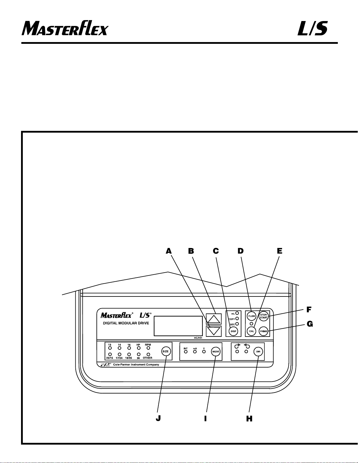
Control/Display Functions
Press buttons to activate function.
Use up/down (▲, ▼) arrows to correct/change a
flashing display.
Press STOP/START to enter new values.
Fonctions de
commande/affichage
Appuyer sur les touches pour activer les fonctions.
Appuyer sur les touches fléchées vers le haut/bas
(▲, ▼) pour corriger/modifier une valeur clignotant
sur l’affichage.
Appuyer sur STOP/START (arrêt/marche) pour
saisir de nouvelles valeurs.
Steuerungs- und
Anzeigefunktionen
Die jeweiligen Funktionen werden durch Betätigen
der Tasten aktiviert.
Mit der Auf- bzw. Abwärtspfeiltaste (▲, ▼) wird
eine blinkende Anzeige korrigiert bzw. geändert.
STOP/START drücken, um neue Werte einzugeben.
A) DOWN ARR OW (DECREMENT)—Decrease
value of a flashing display .
FLÈCHE VERS LE BAS
(DÉCRÉMENTATION)—Réduction d’une
valeur clignotant sur l’affichage.
ABWÄRTSPFEIL (NIEDRIGER)—
Verringert den Wert einer blinkenden Anzeige.
FLECHA ABAJO (DISMINUIR)—
Disminuye el valor de una pantalla intermitente.
FRECCIA RIVOLTA IN BASSO
(DECREMENTO)—Diminuisce il valore nel
display lampeggiante.
B) UP ARROW (INCREMENT)—Increase value
of a flashing display.
FLÈCHE VERS LE HAUT
(INCRÉMENTATION)—Accroissement
d’une valeur clignotant sur l’affichage.
AUFWÄRTSPFEIL (HÖHER)—Erhöht den
Wert einer blinkenden Anzeige.
FLECHA ARRIBA (AUMENTAR)—
Aumenta el valor de una pantalla intermitente.
FRECCIA RIVOLTA IN ALTO
(INCREMENTO)—Aumenta il valore nel
display lampeggiante.
C) DISPENSE/COPY—Select dispensed volume,
number of copies of a dispensed volume, or the
dispense interval.
DISTRIBUTION/RÉPÉTITION—Sélection
du volume distribué, du nombre de répétitions
de cette distribution ou de l’intervalle de
distribution.
FÖRDERN/WIEDERHOLEN (DISP/COPY)—
Wahl der Fördermenge, Anzahl Wiederholungen
einer Fördermenge oder Förderintervalle.
DESCARGAR/COPIAR—Selecciona el
volumen descargado, el número de copias de un
volumen descargado o el intervalo de descarga.
DISTRIBUZIONE/COPIATURA—Seleziona
il volume di distribuzione, il numero di copie
del volume di distribuzione o l’intervallo di
distribuzione.
6
Page 7
®
®
CONTROL/DISPLAY FUNCTIONS
FONCTIONS DE COMMANDE/
AFFICHAGE
STEUERUNGS- UND
ANZEIGEFUNKTIONEN
FUNCIONES DE
CONTROL/VISUALIZACIÓN
FUNZIONI DI
COMANDO/DISPLAY
D) FLOW CONTROL—Set flow rate for selected
tubing size. To change flow rate, press ▼ or ▲
arrows. (If pump is running, its speed will change
with new settings.)
RÉGLAGE DE DÉBIT—Réglage du débit en
fonction du diamètre de tubes sélectionné.
Appuyer sur les touches fléchées ▼ et ▲ pour
modifier le débit. (Si la pompe est en marche, sa
vitesse change en fonction des nouveaux
paramètres.)
TASTE FLOW—Einstellen der Fördermenge für
die ausgewählte Schlauchgröße. Um die
Fördermenge zu ändern, die Aufwärts- ▲ bzw.
Abwärtspfeiltaste ▼ drücken. (Bei laufender
Pumpe ändert sich die Geschwindigkeit
entsprechend den neuen Einstellungen.)
CONTROL DE CAUDAL—Fija el caudal para
el tubo del tamaño seleccionado. Para variar el
caudal, pulse las flechas ▼ o ▲. (Si la bomba está
en marcha, su velocidad cambiará con los nuevos
ajustes.)
REGOLAZIONE DELLA PORTATA—
Imposta la portata secondo la dimensione di tubo
prescelta. Per regolare la portata, premere le
frecce ▼ o ▲ (se la pompa è in funzione, la
portata cambia con le nuove impostazioni).
E) CAL CONTROL—Refine built-in calibration,
using a measured volume.
COMMANDE D’ÉTALONNAGE—Permet
d’affiner l’étalonnage prédéfini à l’aide d’un
volume déterminé.
TASTE CAL—Feineinstellung der internen
Kalibrierung mittels eines gemessenen Volumens.
CONTROL DE CALIBRACIÓN—Refina la
calibración integrada, usando un volumen
medido.
REGOLAZIONE DELLA TARATURA—
Mette a punto la taratura interna in base al volume
misurato.
F) STOP/START—Stop/Start motor.
ARRÊT/MARCHE—Arrêt/mise en marche du
moteur.
STOP/START—Stoppt bzw. startet den Motor.
PARADA/ARRANCAR—Para/Arranca el
motor.
ARRESTO/AVVIO—Arresta/avvia il motore.
G)
PRIME—Run pump at full speed to fill or clear
lines.
AMORÇAGE—Marche de la pompe à la vitesse
maximum pour remplir ou purger les tubes.
PRIME—Pumpe läuft mit voller Geschwindig-
keit, um die Leitungen zu füllen bzw. zu leeren.
CEBAR—Hace funcionar la bomba a plena
velocidad para llenar o vaciar las tuberías.
ADESCAMENTO—Aziona la pompa alla
massima velocità per riempire o scaricare il tubo.
H)
DIRECTION—To change motor direction.
DIRECTION—Inversion du sens de marche du
moteur.
RICHTUNG (DIR)—Ändert die Drehrichtung
des Motors.
SENTIDO—Cambia el sentido de giro del
motor.
SENSO DI ROTAZIONE—Cambia il senso di
rotazione del motore.
I) MODE SELECT—INT for internal control;
mA for remote current control; V for remote
voltage control.
SÉLECTEUR DE MODE—INT pour
commande interne; mA pour réglage d’intensité
à distance; V pour réglage de tension à distance.
MODUSAUSWAHL (MODE)—Modusauswahl:
INT für interne Steuerung; mA für Fernsteuerung
Strom; V für Fernsteuerung Spannung.
SELECCIÓN DE MODALIDAD—INT para
control interno; mA para control remoto de
corriente; V para control remoto de voltaje.
SELEZIONE DI MODALITÀ—INT per la
regolazione interna; mA per la regolazione a
distanza della corrente; V per la regolazione a
distanza della tensione.
J) SIZE—Select tubing size.
DIAMÈTRE—Sélection du diamètre des
tubes.
SIZE—Auswahl der Schlauchgröße.
TAMAÑO—Selecciona el tamaño del tubo.
DIMENSIONE—Seleziona la dimensione del
tubo.
7
Funciones de
Control/Visualización
Pulse los botones para activar la función.
Use las flechas arriba/abajo (▲, ▼) para
corregir/cambiar una pantalla intermitente.
Pulse STOP/START para introducir los valores
nuevos.
Funzioni di comando/display
Per attivare una funzione, premere il pulsante
corrispondente.
Per correggere o modificare il display che
lampeggia, servirsi delle frecce rivolte verso l’alto e
verso il basso (▲, ▼).
Premere il pulsante di arresto/avvio, STOP/START,
per immettere nuovi valori.
Page 8

®
®
8
Setup and Drive Operation
1. Connect Motor Cable plug to mating receptacle
on the Controller.
2. Connect power cord to Controller and grounded
power line outlet.
3. Mount pump head and load tubing. (See pump
head manual.)
4. Turn pump on and select TUBING SIZE.
NOTE: If CAL LED is lit, that tubing size has been
previously field calibrated. If LED is not lit,
the drive is operating with the built-in factory
calibration. To clear a field calibration, press
and hold the CAL switch until the CAL light
goes out. This will take about 3 seconds. To
recalibrate for better accuracy, see Calibration
section.
5. MODE selection (INT, mA, V).
6. Select MOTOR DIRECTION (CW or CCW).
7. PRIME and CALibrate the pump (if required).
8. Press FLOW button and watch display to set the
flow rate with UP/DOWN keys.
9. Press STOP/START button to begin pumping.
NOTE: Pump will restart automatically after a
brownout or powerout condition.
Calibration
Use only MASTERFLEX precision tubing
with MASTERFLEX pumps to ensure optimum
performance. Use of other tubing may void
applicable warranties.
1. Select correct tubing size and flow rate.
2. Press CAL, calibration volume appears.
3. Press STOP/START, the pump will use its stored
memory to dispense the specified calibration
sample quantity. The pump will stop
automatically.
4. Weigh/measure the sample.
5. Use UP/DOWN arrow keys to correct the
flashing display.
NOTE: If the adjusted calibration is too great,
“Err” will appear in the display. If this occurs,
press the CAL control and repeat the
calibration procedure. The microprocessor
will retain one special calibration value per
tubing size, even when power is turned off.
The next calibration will replace the existing
value.
6. Press SIZE to exit the calibration cycle.
Maximum Flowrate (OTHER Tubing)
1. To set the maximum flowrate for non-standard
pumps or tubing sizes OTHER, press CAL, then
FLOW. The maximum flowrate will then flash
on the display.
2. Use UP/DOWN arrow keys to set desired
flowrate.
3. Press SIZE to exit.
Montage und Betrieb
1. Den Motorkabelstecker an die entsprechende
Steckdose des Controllers anschließen.
2. Netzkabel an den Controller und eine geerdete
Netzsteckdose anschließen.
3.
Den Pumpenkopf montieren (siehe die mit dem
Pumpenkopf gelieferte Bedienungsanleitung).
4. Pumpe einschalten und SCHLAUCHGRÖSSE
(SIZE) auswählen
.
HINWEIS: Falls die LED CAL leuchtet, wurde diese
Schlauchgröße bereits vor Ort kalibriert. Wenn
die LED nicht leuchtet, verwendet der Antrieb
die interne werkseitige Kalibrierung. Um eine
vor Ort vorgenommene Kalibrierung zu löschen,
den Schalter CAL drücken und gedrückt halten,
bis die LED CAL erlischt. Dies dauert ca. 3
Sekunden. Zur Erhöhung der Genauigkeit kann
erneut kalibriert werde. Hinweise hierzu finden
Sie im Abschnitt
„
Kalibrierung“.
5. Modus (MODE) wählen: (INT, mA, V).
6. DREHRICHTUNG DES MOTORS (DIR) wählenUhrzeigersinn oder entgegen dem Uhrzeigersinn.
7. Die Pumpe vorfüllen bzw. leeren (PRIME) und
ggf. kalibrieren (CAL).
8. Die Taste FLOW drücken, die Anzeige beobachten
und die Fördermenge mit der AUF- bzw.
ABWÄRTSPFEILTASTE einstellen.
9. STOP/START drücken, um die Pumpe zu starten.
HINWEIS: Nach einer Netzspannungssenkung oder
nach einem Stromausfall wird die Pumpe
automatisch neu gestartet.
Kalibrierung
Um optimale Anwendungsergebnisse zu
gewährleisten, sind für MASTERFLEX Pumpen
ausschließlich MASTERFLEX Präzisionsschläuche
zu verwenden. Der Einsatz anderer Schläuche kann
eine Verweigerung der Garantieleistung nach sich
ziehen.
1. Korrekte Schlauchgröße und Fördermenge wählen.
2. Zur Anzeige der Kalibrierungsmenge CAL
drücken.
3. STOP/START drücken; die Pumpe fördert die
gespeicherte Probenmenge für die Kalibrierung
und stellt sich automatisch ab.
4. Die Probe wiegen und messen.
5. Die blinkende Anzeige mit der AUF- bzw.
ABWÄRTSPFEILTASTE korrigieren.
HINWEIS: Wenn der ermittelte Kalibrierungswert zu
stark vom internen Wert abweicht, wird am
Display „Err“ (Error/Fehler) angezeigt. In
diesem Fall die Taste CAL drücken und die
Kalibrierung wiederholen. Der Mikroprozessor
speichert auch bei ausgeschaltetem Strom
jeweils einen Kalibrierungswert pro
Schlauchgröße. Bei der nächsten Kalibrierung
wird der vorhandene Wert ersetzt.
6. SIZE drücken, um den Kalibrierungsmodus zu
beenden.
Maximale Fördermenge (anderer Schlauch)
1. Um die maximale Fördermenge für nicht
standardmäßige Pumpen oder andere
Schlauchgrößen (OTHER) einzustellen, erst CAL
und dann FLOW drücken. Die maximale
Fördermenge wird als blinkender Wert angezeigt.
2. Die gewünschte Fördermenge mit der AUF- bzw.
ABWÄRTSPFEILTASTE einstellen.
3. SIZE drücken, um die Einstellung zu beenden.
Configuration et fonctionnement
de l’entraînement
1. Brancher la fiche du câble de moteur à la prise
homologue du contrôleur.
2. Raccorder le cordon d’alimentation venant du
contrôleur à la prise secteur 2 pôles + terre.
3. Monter la tête de pompe et charger les tubes. (Voir la
notice de la tête de pompe.)
4. Mettre la pompe sous tension et sélectionner le
DIAMÈTRE DE TUBES.
REMARQUE : si le témoin CAL (étalonnage) est
allumé, l’unité a déjà été étalonnée en clientèle
pour ce diamètre de tube. Si le témoin est éteint,
l’unité fonctionne avec l’étalonnage prédéfini à
l’usine. Pour annuler un étalonnage en clientèle,
appuyer sur la touche CAL et la maintenir
enfoncée jusqu’à ce que le témoin CAL s’éteigne,
ce qui demande 3 secondes environ. Pour
réétalonner l’unité afin d’obtenir une précision
supérieure, voir la section « Étalonnage ».
5. Sélectionner le MODE (INT, mA, V).
6. Sélectionner le sens de marche du moteur (horaire
ou antihoraire).
7. AMORCER et ÉTALONNER la pompe (si
nécessaire).
8. Appuyer sur la touche FLOW (réglage de débit) et
observer la valeur affichée pour régler le débit à l’aide
des touches fléchées VERS LE HAUT/B AS.
9. Appuyer sur la touche STOP/START (arrêt/marche)
pour commencer à pomper.
REMARQUE : la pompe se remet en marche
automatiquement après une baisse de tension ou
une panne de secteur
.
Étalonnage
Utiliser uniquement des tubes extrudés avec
précision MASTERFLEX avec les pompes
MASTERFLEX pour garantir des performances
optimales. L’utilisation d’autres tubes peut annuler
les garanties applicables.
1. Sélectionner le diamètre de tubes et le débit corrects.
2. Appuyer sur la touche CAL, ce qui fait apparaître
le volume auquel l’unité est étalonnée.
3. Appuyer sur la touche STOP/START
(arrêt/marche). La pompe utilise la valeur stockée
dans sa mémoire pour distribuer l’échantillon
spécifié pour l’étalonnage, puis s’arrête
automatiquement.
4. Peser/mesurer l’échantillon.
5. Appuyer sur les touches fléchées VERS LE
HAUT/BAS pour corriger la valeur clignotant sur
l’affichage.
REMARQUE : si l’étalonnage est réglé à une valeur
excessive, « Err » (erreur) s’affiche. Si cela se
produit, appuyer sur la touche CAL et répéter
l’opération d’étalonnage. Le microprocesseur
conserve une valeur d’étalonnage spéciale pour
chaque diamètre de tube, même lorsque l’unité
est hors tension. L’étalonnage suivant remplace
la valeur existante.
6. Appuyer sur SIZE (diamètre) pour mettre fin au
cycle d’étalonnage.
Débit maximum (tubes « OTHER » [non standard])
1. Pour ajuster le débit maximum aux pompes ou
diamètres de tubes non standard (« OTHER »),
appuyer sur CAL, puis sur FLOW. Le débit
maximum clignote alors sur l’affichage.
2. Appuyer sur les touches fléchées VERS LE
HAUT/BAS pour sélectionner le débit désiré.
3. Appuyer sur SIZE (diamètre) pour mettre fin au
réglage.
Page 9

®
®
9
Configuración y Operación del
Propulsor
1. Conecte el enchufe del cable del motor al
receptáculo correspondiente del controlador.
2. Conecte el cable de alimentación al controlador y
a la red eléctrica puesta a tierra.
3. Monte la cabeza de la bomba y tubos de carga.
(Vea el manual de la cabeza de la bomba.)
4. Encienda la bomba y seleccione el TAMAÑO DE
LOS TUBOS.
NOTA: Si está encendido el LED de calibración,
quiere decir que se ha calibrado anteriormente
dicho tamaño de tubo. Si no se enciende el
LED, el propulsor está funcionando con la
calibración integrada en fábrica. Para borrar
una calibración, pulse y mantenga pulsado el
interruptor CAL hasta que se apague la luz
CAL. Esto tardará unos 3 segundos. Para
volver a calibrar para obtener una mayor
precisión, vea la sección de Calibración.
5. Selección de MODALIDAD (INT, mA, V).
6. Seleccione SENTIDO DE GIRO DEL MOTOR
(DERECHA o IZQUIERDA).
7. CEBE y CALIBRE la bomba (si es necesario).
8. Pulse el botón de CAUDAL y observe la pantalla
para fijar el caudal con las teclas
ARRIBA/ABAJO.
9. Pulse el botón PARADA/ARRANCAR para
empezar a bombear.
NOTA: La bomba volverá a arrancar
automáticamente después de una disminución
de voltaje o un corte de corriente.
Calibración
Use solamente tubos de precisión MASTERFLEX
con las bombas MASTERFLEX para asegurar un
rendimiento óptimo. El uso de otros tubos puede
anular las garantías correspondientes.
1. Seleccione el tamaño de los tubos y el caudal
correctos.
2. Pulse CAL y aparecerá el volumen de
calibración.
3. Pulse STOP/START y la bomba usará su
memoria guardada para descargar la cantidad de
muestra de calibración especificada. La bomba
parará automáticamente.
4. Pese/mida la muestra.
5. Use las teclas de flecha ARRIBA/ABAJO para
corregir la pantalla intermitente.
NOTA: Si la calibración ajustada es demasiado
grande, aparecerá “Err” en la pantalla. Si
ocurre esto, pulse el control CAL y repita el
procedimiento de calibración. El
microprocesador retendrá un valor de
calibración especial por tamaño de tubo,
incluso cuando se desconecte la corriente. La
calibración siguiente reemplazará el valor
existente.
6. Pulse SIZE para salir del ciclo de calibración.
Caudal máximo (tubos OTHER)
1. Para fijar el caudal máximo para bombas que no
son estándar o tamaños de tubos OTHER, pulse
CAL y después FLOW. El caudal máximo
destellará en la pantalla.
2. Use las teclas de flecha ARRIBA/ABAJO para
fijar el caudal deseado.
3. Pulse SIZE para salir.
Messa a punto e funzionamento
dell’azionamento
1. Collegare la spina del cavo del motore al connettore
corrispondente nel controller.
2. Collegare il cavo di alimentazione al controller e
alla presa di corrente collegata a terra.
3. Montare la testa pompante e caricare il tubo (vedi il
manuale della testa pompante).
4. Accendere la pompa e selezionare la
DIMENSIONE DEL TUBO.
NOTA - Se il LED della taratura, CAL, è illuminato,
la taratura è stata già effettuata in campo per
quella particolare dimensione di tubo. Se il LED
non è illuminato, l’azionamento funziona con la
taratura interna impostata in fabbrica. Per
azzerare la taratura di campo, mantenere
premuto l’interruttore CAL finché la luce non si
spegne, circa 3 secondi. Per una taratura più
precisa, vedi la sezione sulla taratura.
5. Scegliere la modalità, MODE, (INT, mA, V).
6. Scegliere il senso di rotazione del motore, MOTOR
DIRECTION, (senso orario o antiorario,
CW/CCW).
7. Adescare (PRIME) e tarare (CAL) la pompa (se
occorre).
8. Premere il pulsante FLOW e osservare il display
per impostare la portata mediante i tasti delle frecce
rivolte
verso l’ALTO o verso il BASSO.
9. Premere il tasto di arresto/avvio, STOP/START, per
iniziare a pompare.
NOTA - In seguito ad abbasso o caduta di corrente, la
pompa si riavvia automaticamente.
Taratura
Per ottenere la migliore prestazione delle pompe
MASTERFLEX usare solo tubi di precisione
MASTERFLEX. Usando altri tubi si rischia di
invalidare le eventuali garanzie.
1. Scegliere la dimensione di tubo e la portata idonee.
2. Premere il tasto di taratura, CAL. Viene
visualizzato il volume di taratura.
3. Premere il tasto di arresto/avvio, STOP/START. La
pompa distribuisce il prelievo per la taratura nella
quantità specificata, in base ai dati conservati in
memoria. La pompa si arresta automaticamente.
4. Pesare/misurare il prelievo.
5. Per modificare il display lampeggiante, servirsi dei
tasti delle frecce rivolte in alto (UP) o in basso
(DOWN).
NOTA - Se, in seguito alla regolazione, la taratura è
troppo elevata, nel display viene visualizzato
“Err”. In tal caso, premere il comando della
taratura, CAL, poi ripetere la procedura di
taratura. Il microprocessore conserva in memoria
un valore specifico per ogni dimensione di tubo,
anche se l’alimentazione viene interrotta. Il
valore esistente viene sostituito dal valore della
taratura successiva.
6. Per uscire dal ciclo di taratura, premere il tasto
della dimensione, SIZE.
Portata massima (ALTRI tubi “OTHER”)
1. Per impostare al massimo la portata di pompe nonstandard o la dimensione di ALTRI “OTHER” tubi,
premere il tasto della taratura, CAL, poi il tasto
della portata, FLOW. La portata massima
lampeggia sul display.
2. Servendosi delle frecce rivolte verso l’ALTO e
verso il BASSO, impostare la portata al valore
desiderato.
3. Per uscire, premere il tasto della dimensione, SIZE.
SETUP AND DRIVE OPERATION
CALIBRATION
CONFIGURATION ET
FONCTIONNEMENT DE
L’ENTRAÎNEMENT
ÉTALONNAGE
MONTAGE UND BETRIEB
KALIBRIERUNG
CONFIGURACIÓN Y OPERACIÓN
CALIBRACIÓN
MESSA A PUNTO E
FUNZIONAMENTO
DELL’AZIONAMENTO
TARATURA
Page 10

®
®
10
DISPense/copy
A first press of the DISP key results in the last
entered dispense volume being displayed. The
“mL” annunciator will illuminate and flash. The
INC/DEC keys are used to change the dispense
volume, if desired. The STOP/START key then
initiates delivery of the set volume. The amount
remaining to be dispensed will be displayed during
countdown. The dispense function is exited by
pressing any key except Increment, Decrement,
DISP, or STOP/START.
A second press of the DISP key causes the COPY
annunciator to illuminate and flash. The
STOP/START key is then used to deliver the
desired volume without the need to know the
volume in specific units. A third press of the DISP
key enters the volume dispensed. The COPY
annunciator stops flashing. The STOP/START key
is then used to initiate delivery of the copied
volume. The number of copies dispensed will be
displayed after each dispense. The maximum
number of copies is 9999. The STOP/START key is
used to pause the copy dispense during dispensing;
copy dispense can then be continued using the
STOP/START key.
A fourth press of the DISP key results in the last
entered dispense interval being displayed. The SEC
annunciator will illuminate and flash. The
INC/DEC keys are used to change the dispense
time, if desired, from 1 to 9999 seconds. The
STOP/START key then initiates delivery for the set
time interval. The remaining time will be displayed
during countdown. Pressing the DISP key a fifth
time exits this mode.
Keypad Lockout Enable/Disable
Press and hold FLOW. After five (5) seconds,
display will change to all dashes. Then, while
holding FLOW, press PRIME five (5) times.
Fördern/Wiederholen
(DISP/Copy)
Beim ersten Betätigen der Taste DISP wird die
zuletzt eingegebene Fördermenge angezeigt. Das
Anzeigefeld „mL“ leuchtet auf und blinkt. Falls
erforderlich, kann die Fördermenge mit der AUFbzw. ABWÄRTSPFEILTASTE geändert werden.
Bei Betätigen der Taste STOP/START beginnt die
Förderung der eingestellten Menge. Die noch zu
fördernde Menge wird während des Countdowns
angezeigt. Um die Förderfunktion zu beenden, eine
beliebige Taste mit Ausnahme der AUF- und
ABWÄRTSPFEILTASTE, der Taste DISP und der
Taste STOP/START drücken.
Wenn die Taste DISP zum zweiten Mal gedrückt
wird, leuchtet das Anzeigefeld COPY auf und blinkt.
Dann wird die gewünschte Fördermenge mittels der
Taste STOP/START gefördert, ohne daß die Menge
in bestimmten Einheiten bekannt sein muß. Beim
dritten Drücken der Taste DISP wird die geförderte
Menge eingegeben. Das Anzeigefeld COPY hört auf
zu blinken. Dann kann das kopierte Volumen durch
Betätigen der Taste STOP/START gefördert werden.
Die Anzahl geförderter Wiederholmengen wird nach
jedem Fördervorgang angezeigt. Die maximale
Anzahl geförderter Wiederholmengen ist 9999. Die
Funktion Wiederholen/Fördern kann mit der Taste
STOP/START während des Fördervorgangs
unterbrochen und durch nochmaliges Betätigen der
Taste STOP/START fortgesetzt werden.
Beim vierten Drücken der Taste DISP wird das
zuletzt eingegebene Förderintervall angezeigt. Das
Anzeigefeld SEC leuchtet auf und blinkt. Die
Förderzeit kann mit der AUF- bzw.
ABWÄRTSPFEILTASTE im Bereich von 1 bis 9999
Sekunden geändert werden. Mit der Taste
STOP/START wird dann die Förderung für das
eingestellte Zeitintervall gestartet. Die verbleibende
Förderzeit wird während des Countdowns angezeigt.
Beim fünften Drücken der Taste DISP wird dieser
Modus beendet.
Aktivieren/Deaktivieren der
Tastensperre
Die Taste FLOW drücken und gedrückt halten. Nach
fünf (5) Sekunden zeigt die gesamte Anzeige Striche
an. FLOW weiter gedrückt halten, und PRIME fünf
(5) mal drücken.
Distribution/répétition
Un premier appui sur la touche DISP (distribution)
provoque l’affichage du dernier volume de
distribution saisi. Le témoin « mL » s’allume et
clignote. Les touches INC/DEC
(incrémentation/décrémentation) servent à modifier
le volume distribué si on le désire. L’appui sur la
touche STOP/START (arrêt/marche) déclenche
ensuite la distribution du volume sélectionné. La
quantité restant à distribuer est affichée lors du
décompte. La fonction de distribution est désactivée
par l’appui sur n’importe quelle touche, à l’exception
des touches d’incrémentation, de distribution, DISP
et STOP/START.
Un second appui sur la touche DISP provoque
l’allumage et le clignotement du témoin COPY
(répétition). La touche STOP/START sert ensuite à
distribuer le volume désiré sans qu’il soit nécessaire
de connaître le volume en unités précises. Un
troisième appui sur la touche DISP saisit le volume
distribué. Le témoin COPY arrête de clignoter. La
touche STOP/START est ensuite utilisée pour lancer
la distribution du volume répété. Le nombre de
distributions répétées s’affiche après chaque
distribution. Le nombre maximum de répétitions est
9999. La touche STOP/START est utilisée pour
interrompre la distribution répétée, qu’il est ensuite
possible de reprendre à l’aide de la touche
STOP/START.
Un quatrième appui sur la touche DISP provoque
l’affichage du dernier intervalle de distribution saisi.
Le témoin SEC (secondes) s’allume et clignote. Les
touches INC/DEC servent à modifier l’intervalle si
on le désire entre 1 et 9999 secondes. L’appui sur la
touche STOP/START déclenche ensuite la
distribution à l’intervalle sélectionné. Le temps
restant à s’écouler s’affiche lors du décompte. Un
cinquième appui sur la touche DISP permet de
quitter ce mode.
Activation/désactivation du
verrouillage de clavier
Appuyer sur la touche FLOW (réglage de débit) et la
maintenir enfoncée. Au bout de cinq (5) secondes,
seuls des tirets s’affichent. Puis, tout en maintenant
la touche FLOW enfoncée, appuyer cinq (5) fois sur
PRIME (amorçage).
Page 11

®
®
11
Descargar/Copiar
La primera pulsación de la tecla DISP hace que
aparezca en pantalla el último volumen de descarga.
El anunciador “mL” se encenderá y destellará. Las
teclas aumentar/disminuir se usan para cambiar el
volumen de descarga, si se desea. La tecla
STOP/START inicia luego la descarga del volumen
fijado. La cantidad restante que se va a descargar se
mostrará durante el conteo hacia atrás. La función
de descarga se abandona pulsando cualquier tecla
excepto las teclas aumentar, disminuir, DISP o
STOP/START.
Una segunda pulsación de la tecla DISP hace que se
encienda y destelle el anunciador COPY. La tecla
STOP/START se usa para suministrar el volumen
deseado sin necesidad de saber el volumen en
unidades específicas. Una tercera pulsación de la
tecla DISP permite introducir el volumen
descargado. El anunciador COPY deja de destellar.
A continuación se usa la tecla STOP/START para
iniciar el suministro del volumen copiado. El
número de copias descargadas se mostrará después
de cada descarga. El máximo número de copias es
9999. La tecla STOP/START se usa para detener el
proceso de copia/descarga. Este proceso puede
continuarse usando la tecla STOP/START.
La cuarta pulsación de la tecla DISP hace que
aparezca el último intervalo de descarga
introducido. El anunciador SEC se encenderá y
destellará. Las teclas de aumentar/disminuir
(INC/DEC) se usan para cambiar el tiempo de
descarga, si se desea, de 1 a 9999 segundos. La tecla
STOP/START inicia después el suministro para el
intervalo fijado. El tiempo restante se mostrará
durante la cuenta atrás. La pulsación de la tecla
DISP por quinta vez permite salir de esta
modalidad.
Activación/Desactivación del
Bloqueo del Teclado
Pulse y mantenga pulsado FLOW. Después de cinco
(5) segundos, la pantalla cambiará a todo guiones.
Después, mientras se mantiene pulsado FLOW,
pulse PRIME cinco (5) veces.
Distribuzione/copiatura
Quando si preme una prima volta il tasto di
distribuzione, DISP, viene visualizzato l’ultimo
volume immesso. L’indicatore “mL” si illumina e
lampeggia. Il volume di distribuzione eventualmente
può essere regolato mediante i tasti di
incremento/decremento, INC/DEC. Premendo il tasto
di arresto/avvio, STOP/START, si dà inizio alla
distribuzione secondo il volume impostato. La
quantità che rimane da distribuire viene indicata nella
conta all’indietro. Per uscire dalla funzione di
distribuzione, premere un qualsiasi tasto ad
eccezione dei tasti di incremento, decremento,
distribuzione, DISP, o arresto/avvio, STOP/START.
Quando si preme una seconda volta il tasto della
distribuzione, DISP, l’indicatore della copiatura,
COPY, si illumina e lampeggia. Il tasto di
arresto/avvio, STOP/START, può essere usato, allora,
per la distribuzione secondo il volume desiderato
senza che sia necessario conoscerne le unità
specifiche. Se si preme una terza volta il tasto di
copiatura/distribuzione, DISP, si immette il volume
della quantità distribuita. L’indicatore di copiatura,
COPY, smette di lampeggiare. Il tasto di
arresto/avvio, STOP/START, può allora essere usato
per iniziare la distribuzione secondo le copie del
volume. Il numero delle copie, fino ad un massimo di
9999, viene visualizzato dopo ciascuna distribuzione.
Per arrestare temporaneamente la distribuzione delle
copie durante l’operazione di distribuzione, premere
il tasto di arresto/avvio. La distribuzione delle copie,
allora, si può continuare mediante il tasto di
arresto/avvio, STOP/START.
Se si preme una quarta volta il tasto di distribuzione,
DISP, viene visualizzato l’ultimo intervallo di
distribuzione immesso. L’indicatore SEC si illumina
e lampeggia. Il tempo di distribuzione eventualmente
può essere regolato tra 1 e 9999 secondi mediante i
tasti di incremento/decremento, INC/DEC. Premendo
poi il tasto di arresto/avvio, STOP/START, si dà
inizio alla distribuzione secondo l’intervallo di tempo
prestabilito. Il tempo rimasto viene visualizzato nella
conta all’indietro. Premendo una quinta volta il tasto
di distribuzione, DISP, si esce da questa modalità.
Abilitazione/disabilitazione della
funzione di blocco della tastiera
Mantenere premuto il tasto della portata, FLOW.
Dopo cinque (5) secondi, il display cambia
visualizzando tutti trattini. Mantenendo premuto il
tasto di portata FLOW, premere cinque (5) volte il
tasto di adescamento, PRIME.
DISPENSE/COPY
KEYPAD LOCKOUT ENABLE/DISABLE
DISTRIBUTION/RÉPÉTITION
ACTIVATION/DÉSACTIVATION DU
VERROUILLAGE DE CLAVIER
FÖRDERN/WIEDERHOLEN
(DISP/COPY)
AKTIVIEREN/DEAKTIVIEREN DER
TASTENSPERRE
DESCARGAR/COPIAR
ACTIVACIÓN/DESACTIVACIÓN DEL
BLOQUEO DEL TECLADO
DISTRIBUZIONE/COPIATURA
ABILITAZIONE/DISABILITAZIONE DELLA
FUNZIONE DI BLOCCO DELLA
TASTIERA
Page 12

®
®
REMOTE CONTROL
Selectable input (0-20 mA, 4-20 mA, 0-10V DC )
±0.5% linearity control
2300V isolation potential
START/STOP; CW/CCW; PRIME via contact
closure
Remote Control Setup
1. Place the power switch in the off position.
CAUTION: Power must be turned off before
connecting the external remote control
cable to prevent damage to the drive.
2. Connect the cable from the external remote
control to the DB15-pin receptacle on the rear
panel. On washdown units, connect to the mating
receptacle on the bottom panel.
3. Select type of remote control input and output
required as follows:
a). Press and hold the MODE control while
turning the power switch to the on position.
After two seconds, release the MODE
control. The initial display will show: “inP”.
After two seconds the display will show
either 0-20 or 4-20.
NOTE: Press the up (increment) or down
(decrement) arrows to select between 4-20
and 0-20 for current loop control.
b). Press the MODE control again. The initial
display will show: “out”. After two seconds
the display will show either 0-20 or 4-20.
NOTE: Press the up (increment) or down
(decrement) arrows to select between 4-20
and 0-20 for current loop output.
4. Press the MODE control to select mode of
operation. The LED’s indicate the selected
mode. Select either mA or V.
NOTE: If only remote STOP/START, PRIME
and/or CW/CCW is to be used, the MODE
control can be set to any of the three
positions.
EXTERNE STEUERUNG
Wählbarer Eingang (0-20 mA, 4-20 mA,
0-10 V Gleichstrom)
±0,5% Linearitätskontrolle
2300 V Isolierungspotential
START/STOP; CW/CCW (Uhrzeigersinn/
Gegenuhrzeigersinn); PRIME (Vorfüllen/Leeren)
über Kontaktschließung
Einrichten der externen
Steuerung
1. Schalter Ein/Aus auf AUS stellen.
VORSICHT: Um eine Beschädigung des Antriebs
zu verhindern, muß der Strom vor
Anschließen des externen
Fernsteuerungskabels ausgeschaltet
werden.
2. Das Kabel von der externen Fernsteuerung an die
15-polige DB15-Anschlußbuchse an der
Rückwand anschließen. Bei Abspritzeinheiten an
die entsprechende Anschlußbuchse an der
Unterseite anschließen.
3. Den erforderlichen Ein- und Ausgangstyp der
externen Steuerung wie folgt auswählen:
a) Den Schalter MODE drücken und gedrückt
halten und dabei den Schalter Ein/Aus auf die
Stellung EIN drehen. Nach zwei Sekunden die
Taste MODE loslassen. Zuerst erscheint auf der
Anzeige „inP“, nach zwei Sekunden entweder
0-20 oder 4-20.
HINWEIS: Die Auf- (Höher) bzw.
Abwärtspfeiltaste (Niedriger) drücken, um für
die Stromschleifensteuerung den Bereich 4-20
oder 0-20 auszuwählen.
b) Die Taste MODE erneut drücken. Zuerst
erscheint auf der Anzeige „out“, nach zwei
Sekunden entweder 0-20 oder 4-20.
HINWEIS: Die Aufwärts- (Höher) bzw.
Abwärtspfeiltaste (Niedriger) drücken, um für
den Stromschleifenausgang 4-20 oder 0-20
auszuwählen.
4. Zur Auswahl der Betriebsart die Taste MODE
drücken. Die LEDs zeigen die ausgewählte
Betriebsart an. Entweder mA oder V wählen.
HINWEIS: Wenn nur STOP/START, PRIME
und/oder CW/CCW (Uhrzeigersinn/
Gegenuhrzeigersinn) für die externe Steuerung
verwendet werden sollen, kann der Schalter
MODE beliebig auf eine der drei Positionen
eingestellt werden.
COMMANDE À DISTANCE
Entrée sélectionnable (0-20 mA, 4-20 mA,
0-10 V c.c.)
Contrôle de linéarité à ±0,5 %
Potentiel d’isolement de 2300 V
MARCHE/ARRÊT, SENS HORAIRE/
ANTIHORAIRE, AMORÇAGE par fermeture
des contacts
Configuration de la commande à
distance
1. Placez le commutateur d’alimentation en position
de mise hors tension.
ATTENTION : l’unité doit être mise
tension avant le raccordement du câble de
la télécommande extérieure pour éviter
d’endommager l’entraînement.
2. Raccorder le câble venant de la télécommande
extérieure à la prise DB 15 broches du panneau
arrière. Raccorder celui des unités de lavage à la
prise homologue du panneau inférieur.
3. Sélectionner le type d’entrée et de sortie de
télécommande en procédant comme suit :
a). Appuyer sur la touche MODE et la maintenir
enfoncée, tout en tournant le commutateur
d’alimentation en position de mise sous
tension. Relâcher la touche MODE au bout de
deux secondes. « inP » (entrée) s’affiche
initialement. Au bout de deux secondes, 0-20
ou 4-20 s’affiche.
REMARQUE : appuyer sur la touche fléchée vers le
haut (incrémentation) ou vers le bas
(décrémentation) pour sélectionner 4-20 ou
0-20 pour le réglage de boucle de courant.
b). Réappuyer sur la touche MODE. « out »
(sortie) s’affiche initialement. 0-20 ou 4-20
s’affiche au bout de deux secondes.
REMARQUE : appuyer sur la touche fléchée vers le
haut (incrémentation) ou vers le bas
(décrémentation) pour sélectionner 4-20 ou
0-20 pour le réglage de boucle de courant.
4. Appuyer sur la touche MODE pour sélectionner le
mode de fonctionnement. Les témoins indiquent
le mode sélectionné. Sélectionner mA ou V.
REMARQUE : si seule la commande ARRÊT/
MARCHE, AMORÇAGE et/ou SENS
HORAIRE/ANTIHORAIRE à distance doit
être utilisée, la commande MODE peut être
réglée dans l’une de ces trois positions.
12
Page 13
®
®
CONTROL REMOTO
Entrada seleccionable (0-20 mA, 4-20 mA,
0-10 VCC)
Control de linealidad de ± 0,5%
Potencial de aislamiento de 2300 V
ARRANQUE/PARADA; DERECHA/IZQUIERDA;
CEBAR por medio de cierre de contactos
Configuración de control remoto
1. Ponga el interruptor de alimentación en la
posición de apagado.
PRECAUCIÓN: Se debe desconectar la corriente
antes de conectar el cable de control
remoto externo para impedir daños en el
propulsor.
2. Conecte el cable del control remoto externo al
receptáculo DB de 15 clavijas en el panel trasero.
En las unidades de lavado, conéctelo al
receptáculo correspondiente del panel inferior.
3. Seleccione el tipo de entrada y salida de control
remoto necesarios de la forma siguiente:
a). Pulse y mantenga pulsado el control MODE
mientras pone el interruptor de encendido en la
posición de encendido. Después de dos
segundos, suelte el control MODE. La pantalla
inicial mostrará: “inP”. Después de dos
segundos, la pantalla mostrará 0-20 ó 4-20.
NOTA: Pulse las flechas arriba (aumentar) o abajo
(disminuir) para seleccionar entre 4-20 y 0-20
para el control del circuito de corriente.
b). Pulse nuevamente el control MODE. La
pantalla inicial mostrará: “out”. Después de
dos segundos, la pantalla mostrará 0-20 ó
4-20.
NOTA: Pulse las flechas arriba (aumentar) o abajo
(disminuir) para seleccionar entre 4-20 y 0-20
para el control del circuito de corriente.
4. Pulse el control MODE para seleccionar la
modalidad de operación. Los LED indican la
modalidad seleccionada. Seleccione mA o V.
NOTA: Si sólo se usa PARADA/ARRANCAR,
CEBAR o DERECHA/IZQUIERDA remoto, el
control MODE puede fijarse en cualquiera de
las tres posiciones.
TELECOMANDO
Ingresso selezionabile (da 0 a 20 mA, da 4 a 20 mA,
da 0 a 10 V in c.c.)
Controllo lineare: ±0,5%
Potenziale di isolamento: 2300V
Avvio/arresto (START/STOP); senso
orario/antiorario (CW/CCW); adescamento (PRIME)
mediante chiusura di contatto.
Messa a punto del telecomando
1. Portare l’interruttore di alimentazione alla
posizione Off.
USARE CAUTELA - Per non danneggiare
l’azionamento, disinnestare
l’alimentazione di corrente prima di
collegare il cavo del telecomando esterno.
2. Collegare il cavo dal telecomando esterno al
connettore DB a 15 pin nel pannello posteriore.
Nelle unità di lavaggio, effettuare il collegamento
al connettore corrispondente nel pannello
inferiore.
3. Scegliere il tipo di ingresso/uscita del
telecomando nel seguente modo.
a) Mantenendo premuto il comando di modalità,
MODE, girare l’interruttore di alimentazione
alla posizione On. Dopo due secondi, rilasciare
il comando di modalità. Il display inizialmente
visualizza: “inP”. Dopo due secondi visualizza
0-20 oppure 4-20.
NOTA - Premere le frecce rivolte verso l’alto
(incremento) o verso il basso (decremento) per
scegliere tra 4-20 e 0-20 per il controllo del
circuito elettrico ad anello.
b) Premere nuovamente il tasto di modalità.
Inizialmente viene visualizzato: “out” (uscita) e
dopo due secondi, viene visualizzato 0-20
oppure 4-20.
NOTA - Premere le frecce rivolte verso l’alto
(incremento) o verso il basso (decremento) per
scegliere tra 4-20 e 0-20 per l’uscita del circuito
elettrico ad anello.
4. Premere MODE per scegliere la modalità di
operazione. Il LED indica la modalità scelta.
Scegliere mA o V.
NOTA - Se si usano solo i comandi di arresto/avvio,
adescamento e/o senso orario/antiorario, il
comando della modalità può essere impostato
ad una qualsiasi delle tre posizioni.
REMOTE CONTROL
COMMANDE À DISTANCE
EXTERNE STEUERUNG
CONTROL REMOTO
TELECOMANDO
13
Page 14
®
®
14
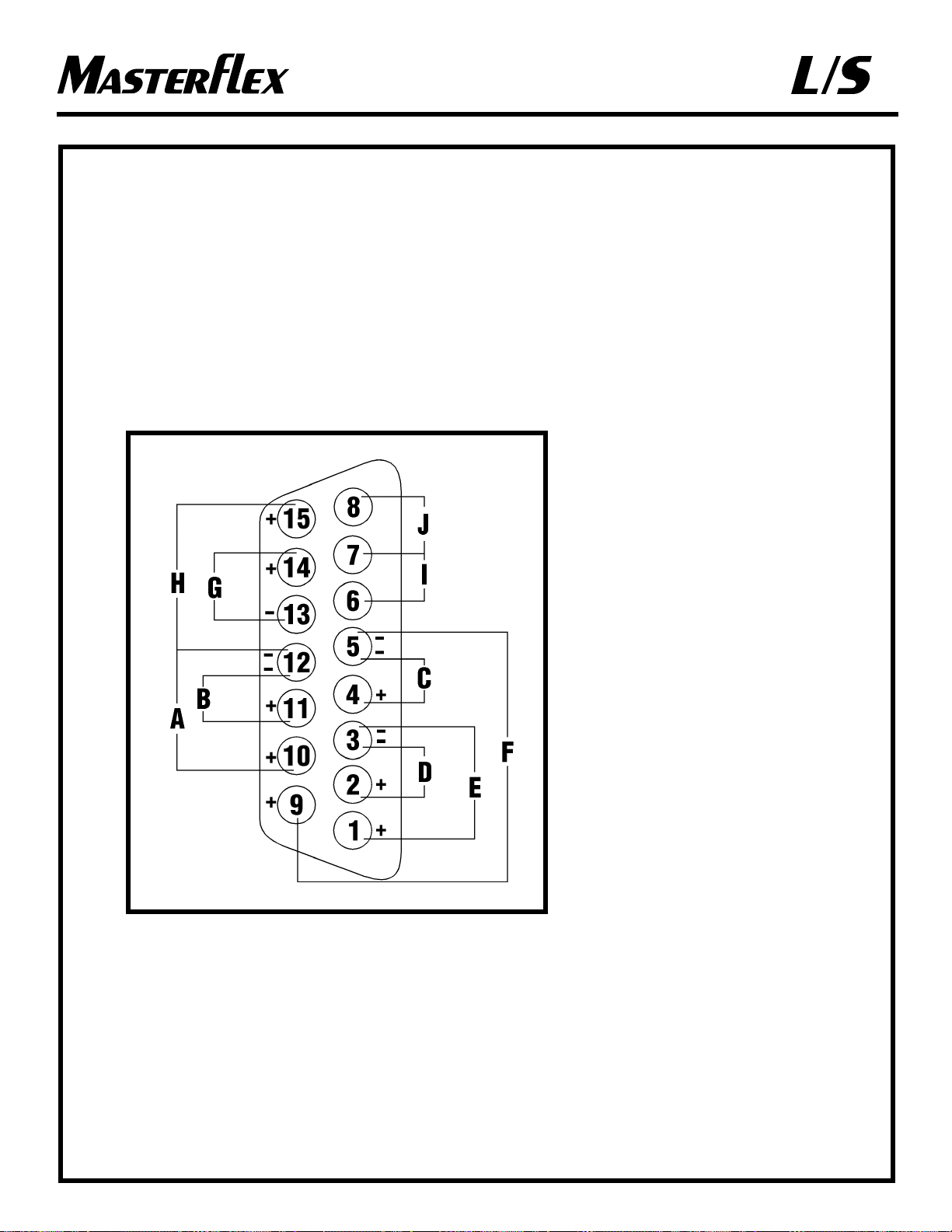
Connector pin configuration/with
wiring scheme
Configuration des broches de
connecteur et schéma de câblage
Belegung der Anschlußbuchse mit
Schaltplan
Configuración de las clavijas de
conector con diagrama de
conexiones
Configurazione dei pin del
connettore con schema di cablaggio
A) ST ART/STOP
MARCHE/ARRÊT
START/STOP
ARRANCAR/PARADA
AVVIO/ARRESTO
B) CW/CCW
SENS HORAIRE/ANTIHORAIRE
CW/CCW (UHRZEIGERSINN/
GEGENUHRZEIGERSINN)
DERECHA/IZQUIERDA
SENSO ORARIO/ANTIORARIO
C) OUTPUT 0-20mA; 4-20mA
SORTIE 0-20mA; 4-20mA
AUSGANG 0-20 mA; 4-20 mA
SALIDA 0-20 mA; 4-20 mA
USCITA da 0 a 20 mA; da 4 a 20 mA
D) INPUT 0-20mA; 4-20mA
ENTRÉE 0-20mA; 4-20mA
EINGANG 0-20 mA; 4-20 mA
ENTRADA 0-20 mA; 4-20 mA
INGRESSO da 0 a 20 mA; da 4 a 20 mA
E) INPUT 0-10V
ENTRÉE 0-10V
EINGANG 0-10V
ENTRADA 0-10V
INGRESSO da 0 a 10 V
F) OUTPUT 0-10V
SORTIE 0-10V
AUSGANG 0-10V
SALIDA 0-10V
USCITA da 0 a 10 V
G) T ACH OUTPUT
SORTIE COMPTE-TOURS
TACHO AUSGANG
SALIDA DE TACÓMETRO
USCITA TACHEOMETRO
H) PRIME
AMORÇAGE
PRIME (VORFÜLLEN/LEEREN)
CEBAR
ADESCAMENTO
I) MOTOR RUNNING N.O. CONTACT
CONTACT OUVERT AU REPOS DE
MOTEUR EN MARCHE
MOTORLAUF SCHLIESSKONTAKT
MOTOR EN MARCHA CONTACTO
NORMALMENTE ABIERTO
CONTATTO NORMALMENTE APERTO,
MOTORE IN FUNZIONE
J) MOTOR RUNNING N.C. CONTACT
CONTACT FERMÉ AU REPOS DE
MOTEUR EN MARCHE
MOTORLAUF RUHEKONTAKT
MOTOR EN MARCHA CONTACTO
NORMALMENTE CERRADO
CONTATTO NORMALMENTE CHIUSO,
MOTORE IN FUNZIONE
77300-80, -85
Page 15

®
®
15
G1) BLACK
NOIR
SCHWARZ
NEG
NERO
H1) BROWN
MARRON
BRAUN
MAR
MARRONE
I1) VIOLET
VIOLET
VIOLETT
VIO
VIOLA
J1) RED
ROUGE
ROT
ROJ
ROSSO
K1) GREY
GRIS
GRAU
GRI
GRIGIO
L1) T AN
OCRE
HELLBRAUN
TOS
MARRONE CHIARO
M1) PINK
ROSE
ROSA
ROS
ROSA
N1) RED/GREEN
ROUGE/VERT
ROT/GRÜN
ROJ/VER
ROSSO/VERDE
O1) RED/BLACK
ROUGE/NOIR
ROT/SCHWARZ
ROJ/NEG
ROSSO/NERO
P1, Q1, R1)
N.C.
FERMÉ AU REPOS
NICHT BELEGT
N.C.
N.C.
77300-90, -95
NOTE: Colors are those of Remote Cable, Cat. number MN-77300-32.
REMARQUE : les couleurs sont celles du câble de télécommande, numéro catalogue MN-77300-32.
HINWEIS: Die Farben gelten für das Kabel der Fernbedienung, Katalognr. MN-77300-32.
NOTA: Los colores son los del cable remoto, no. de catálogo MN-77300-32.
NOTA: i colori sono quelli del cavo remoto, codice catalogo MN-77300-32.
A1) RED/YELLOW
ROUGE/JAUNE
ROT/GELB
ROJ/AMA
ROSSO/GIALLO
B1) BLUE
BLEU
BLAU
AZUL
BLU
C1) GREEN
VERT
GRÜN
VER
VERDE
D1) YELLOW
JAUNE
GELB
AMA
GIALLO
E1) WHITE
BLANC
WEISS
BLA
BIANCO
F1) ORANGE
ORANGE
ORANGE
NAR
ARANCIONE
Page 16

®
®
DÉPANNAGE ET ENTRETIEN/
DIMENSIONS DE MONTAGE
DANGER : l’entretien des systèmes
d’entraînement modulaires ne peut être
effectué par le client, à l’exception du
remplacement des FUSIBLES, BALAIS
DE MOTEUR ET PIGNONS.
AVERTISSEMENT : débrancher le contrôleur
avant de vérifier ou de remplacer les
FUSIBLES et/ou les BALAIS DE
MOTEUR et les PIGNONS.
TROUBLESHOOTING AND
MAINTENANCE/MOUNTING
DIMENSIONS
DANGER: Modular Drive Systems are not
customer serviceable, except for
replacement of FUSES, MOTOR
BRUSHES and GEARS.
WARNING: Unplug Controller prior to
checking or replacing FUSES and/or
MOTOR BRUSHES and GEARS.
STÖRUNGSBESEITIGUNG
UND WARTUNG/
MONTAGEABMESSUNGEN
VORSICHT, LEBENSGEFAHR: Abgesehen vom
Austauschen der SICHERUNGEN,
KOHLEBÜRSTEN und
GETRIEBERÄDER dürfen die
modularen Antriebssysteme nicht vom
Kunden gewartet werden.
VORSICHT: Vor Prüfen oder Auswechseln der
SICHERUNGEN und/oder
KOHLEBÜRSTEN und
GETRIEBERÄDER das Netzkabel
des Controllers ziehen.
A)6-600 RPM GEAR ASSEMBLY
(included in service kit 77300-01)
PIGNON 6-600 TR/MN
(inclus dans le kit d’entretien 77300-01)
GETRIEBERAD TYP 6-600 U/min
(in Service-Kit 77300-01 enthalten)
CONJUNTO DE ENGRANAJES DE
6-600 RPM (incluido en el juego de servicio
77300-01)
GRUPPO INGRANAGGI 6-600 GIRI/MIN
(incluso nel kit di manutenzione 77300-01)
B)GASKET
JOINT D’ÉTANCHÉITÉ
DICHTUNG
EMPAQUETADURA
GUARNIZIONE
C)CAP
CAPUCHON
ABDECKKAPPE
TAPA
TAPPO
16
D)MO T OR BRUSH
BALAIS DE MOTEUR
KOHLEBÜRSTE
ESCOBILLA DE MOTOR
SPAZZOLA MOTORE
E)GEAR CASE COVER ASSEMBLY
COUVERCLE DU BOÎTIER
D’ENGRENAGE
ABDECKUNG DES ANTRIEBSGEHÄUSES
CONJUNTO DE TAPA DE CAJA DE
ENGRANAJES
COPERCHIO SCATOLA INGRANAGGI
Mounting Dimensions for Model
Numbers 77300-30, -35
Dimensions de montage pour les
modèles numéros : 77300-30, -35
Montageabmessungen für
Modellnummern: 77300-30, -35
Dimensiones para montar para los
números de modelo 77300-30, -35
Dimensioni per il montaggio di
modelli numero 77300-30, -35
CLEARANCE FOR 1/4 IN SCREW
DÉGAGEMENT POUR VIS DE 6 mm
ABSTAND FÜR 6 mm ZOLL SCHRAUBE
ESPACIO PARA TORNILLO DE 6 mm
SPAZIO PER VITE DA 6 mm
Page 17

®
®
INDIVIDUAZIONE E RISOLUZIONE
DI PROBLEMI E MANUTENZIONE/
DIMENSIONI DI MONTAGGIO
PERICOLO - Ad eccezione della sostituzione di
FUSIBILI, SPAZZOLE MOTORE e
INGRANAGGI, la manutenzione o la
reparazione dei sistemi degli azionamenti
modulari non possono essere effettuate dal
cliente.
ATTENZIONE - Prima di controllare o sostituire i
FUSIBILI e le SPAZZOLE DEL
MOTORE e gli INGRANAGGI, scollegare
il controller.
LOCALIZACIÓN DE AVERÍAS
Y MANTENIMIENTO/
DIMENSIONES PARA MONTAR
PELIGRO: Los sistemas propulsores
modulares no son reparables por el
cliente, excepto al reemplazo de
FUSIBLES, ESCOBILLAS DE
MOTOR y ENGRANAJES.
ADVERTENCIA: Desenchufe el controlador
antes de comprobar o reemplazar
FUSIBLES o ESCOBILLAS DE
MOTOR y ENGRANAJES.
TROUBLESHOOTING AND
MAINTENANCE/MOUNTING
DIMENSIONS
MOTOR BRUSH CHECK/REPLACEMENT
DÉPANNAGE ET
ENTRETIEN/DIMENSIONS DE
MONTAGE
CONTRÔLE ET REMPLACEMENT DES
BALAIS DE MOTEUR
STÖRUNGSBESEITIGUNG UND
WARTUNG/
MONTAGEABMESSUNGEN
ÜBERPRÜFEN UND AUSWECHSELN DER
KOHLEBÜRSTEN
LOCALIZACIÓN DE AVERÍAS Y
MANTENIMIENTO/
DIMENSIONES PARA MONTAR
COMPROBACIÓN/REEMPLAZO DE LA
ESCOBILLAS DE MOTOR
INDIVIDUAZIONE E
RISOLUZIONE DI PROBLEMI E
MANUTENZIONE/DIMENSIONI
DI MONTAGGIO
CONTROLLO E SOSTITUZIONE DELLE
SPAZZOLE DEL MOTORE
A) T3.15A FUSE (115V AC); T1.6A FUSE (230V AC)
CAUTION: Do not substitute.
T3. FUSIBLE 15 A (115 V c.a.); T1. FUSIBLE 6 A
(230 V c.a.) ATTENTION : ne pas en substituer
un autre.
T3.15 A SICHERUNG (115 V~); T1.6 A SICHERUNG
(230 V~) ACHTUNG: Keinen anderen Ersatz
verwenden.
FUSIBLE T3.15A (115 VCA); FUSIBLE T1.6A
(230 VCA) PRECAUCIÓN: No lo sustituya.
FUSIBILE T3.15A (115V c.a.), FUSIBILE T1.6A
(230V c.a.) USARE CAUTELA: non sostituire.
B) EXTERNAL RECEPT ACLE
PRISE EXTÉRIEURE
ANSCHLUSS FÜR EXTERNE STEUERUNG
RECEPTÁCULO EXTERNO
CONNETTORE ESTERNO
C) IEC 320 POWER ENTRY MODULE/LINE CORD
MODULE D’ALIMENTATION IEC 320/CORDON
D’ALIMENTATION
NETZANSCHLUSS/NETZKABEL NACH IEC 320
MÓDULO DE ENTRADA DE CORRIENTE/CORDÓN
DE RED IEC 320
CAVO DI ALIMENTAZIONE/PRESA DI
ALIMENTAZIONE IEC 320
D) MOTOR RECEPTACLE
PRISE DU MOTEUR
ANSCHLUSSBUCHSE, MOTOR
RECEPTÁCULO DE MOTOR
CONNETTORE DEL MOTORE
E) POWER SWITCH — ALL SETTINGS ARE
RETAINED IN MEMORY
COMMUTATEUR D’ALIMENTATION — TOUS LES
PARAMÈTRES SONT CONSERVÉS EN MÉMOIRE
SCHALTER EIN/AUS — ALLE EINSTELLUNGEN
BLEIBEN GESPEICHERT
INTERRUPTOR DE ALIMENTACIÓN — T ODOS
LOS AJUSTES SON RETENIDOS EN MEMORIA
INTERRUTTORE DI ALIMENTAZIONE — TUTTE
LE IMPOSTAZIONI SONO CONSERVATE IN
MEMORIA
77300-90, -95
17
77300-80, -85
Page 18

®
®
ÜBERPRÜFEN UND
AUSWECHSELN DER
KOHLEBÜRSTEN
Die Bürsten müssen alle 6 Monate oder nach jeweils
2000 Betriebsstunden geprüft werden, oder wenn
sich Fehler in der Anwendung bemerkbar machen.
Unmittelbar nach dem Auswechseln der Bürsten
kann es zu unregelmäßigem Betrieb kommen. Den
Motor bis zu einer Stunde laufen lassen, damit sich
die Bürsten einschleifen können.
VORSICHT, LEBENSGEFAHR: Im modularen
Antrieb herrscht Hochspannung, die
unter Umständen zugänglich ist. Bis auf
den Austausch von SICHERUNGEN,
KOHLEBÜRSTEN und/oder
GETRIEBERÄDER dürfen
Wartungsarbeiten nur von qualifiziertem
Personal vorgenommen werden.
Zum Auswechseln der Bürsten die 2
Gummiabdeckkappen entfernen und die Bürsten
abschrauben.
Bürsten auf Risse und Abnutzungserscheinungen
prüfen.
Beide Bürsten auswechseln, wenn eine Bürste bis auf
weniger als 7,6 mm abgenutzt ist.
Falls eine weitere Überprüfung erforderlich ist,
wenden Sie sich bitte an Ihren Fachhändler.
MOTOR BRUSH
CHECK/REPLACEMENT
Brushes should be checked every 6 months or 2000
operating hours or if erratic operation occurs.
Erratic operation may occur immediately after brush
replacement. Allow motor to run up to an hour to
allow brushes to seat.
DANGER: High voltages exist and are accessible
in the Modular Drive. Other than the
replacement of FUSES, MOTOR
BRUSHES and/or GEARS, refer
servicing to qualified personnel.
To replace the brushes, remove the 2 rubber caps
and unscrew the brushes.
Inspect for cracks and excessive wear.
Replace both brushes, if either brush is less than
7.6 mm (0.300 in) long from base to point.
Contact your dealer if you have service needs.
CONTRÔLE ET REMPLACEMENT
DES BALAIS DE MOTEUR
Les balais doivent être contrôlés tous les 6 mois ou
toutes les 2000 heures de fonctionnement, ou en cas
d’irrégularité de marche.
Le fonctionnement risque d’être irrégulier
immédiatement après le remplacement des balais.
Laisser le moteur tourner pendant une heure au
maximum pour permettre aux balais de se mettre en
place.
DANGER : des hautes tensions auxquelles on
peut être exposé sont présentes dans
l’entraînement modulaire. En dehors du
remplacement des FUSIBLES, des
BALAIS DE MOTEUR et/ou des
ENGRENAGES, faire effectuer
l’entretien par du personnel qualifié.
Pour remplacer les balais, retirer les 2 capuchons en
caoutchouc et dévisser les balais.
Examiner les balais pour voir s’ils sont fêlés et si
leur usure est excessive.
Remplacer les deux balais si l’un d’eux est long de
moins de 7,6 mm de la base á la pointe.
S’adresser au revendeur en cas de besoin.
18
Page 19

®
®
CONTROLLO E SOSTITUZIONE
DELLE SPAZZOLE DEL MOTORE
Le spazzole devono essere controllate ogni 6 mesi
od ogni 2000 ore d’esercizio oppure se il
funzionamento è erratico.
Immediatamente dopo la sostituzione delle spazzole,
il funzionamento può essere erratico. Tenere il
motore in funzione per un’ora al massimo in modo
da consentire alle spazzole di stabilizzarsi.
PERICOLO - Internamente all’azionamento
modulare si trovano componenti ad alta
tensione. Ad eccezione della sostituzione
di FUSIBILI, SPAZZOLE MOTORE e/o
INGRANAGGI, gli interventi di
manutenzione e riparazione devono
essere effettuati da personale qualificato.
Per sostituire le spazzole, rimuovere i due tappi di
gomma e svitare le spazzole.
Controllare che non ci siano incrinature o usura
eccessiva.
Se una delle spazzole misura meno di 7,6 mm di
lunghezza dalla base alla punta, sostituire entrambe
le spazzole.
Se occorre riparare la macchina, rivolgersi al
concessionario.
COMPROBACIÓN/REEMPLAZO
DE ESCOBILLAS DE MOTOR
Las escobillas deben comprobarse cada 6 meses o
2000 horas de operación o si se produce una
operación irregular.
Se puede producir una operación irregular
inmediatamente después de reemplazar las
escobillas. Deje que el motor funcione hasta una hora
para permitir el asentamiento de las escobillas.
PELIGRO: Existen altos voltajes y están
presentes en el propulsor modular. Con
excepción del reemplazo de FUSIBLES,
ESCOBILLAS DE MOTOR o
ENGRANAJES, el servicio debe ser
efectuado por personas capacitadas.
Para reemplazar las escobillas, quite las 2 tapas de
goma y destornille las escobillas.
Inspeccione las escobillas para ver si están agrietadas
y excesivamente desgastadas.
Reemplace ambas escobillas, si cualquiera de las
escobillas mide menos de 7,6 mm de largo de la base
a la punta.
Póngase en contacto con su distribuidor si necesita
servicio.
TROUBLESHOOTING AND
MAINTENANCE
DÉPANNAGE ET ENTRETIEN
STÖRUNGSBESEITIGUNG
LOCALIZACIÓN DE AVERÍAS Y
MANTENIMIENTO
INDIVIDUAZIONE E RISOLUZIONE
DI PROBLEMI
19
Page 20

®
®
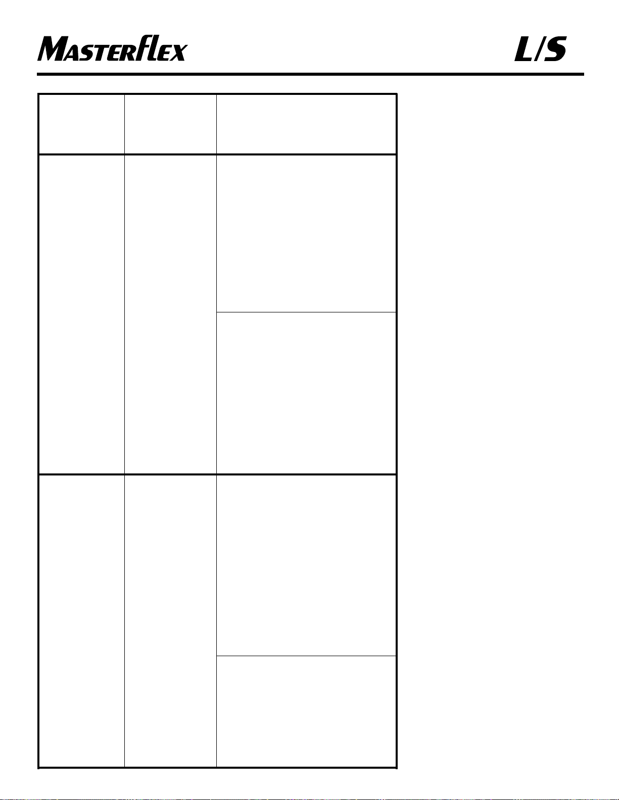
A. Motor does not rotate. Display does not light.
Le moteur ne tourne pas et l’affichage ne
s’allume pas.
Motor dreht sich nicht. Anzeige leuchtet nicht.
El motor no gira. La pantalla no se ilumina.
Il motore non funziona. Il display non si
illumina.
A1. No power.
Pas d’alimentation.
Kein Strom.
No hay corriente.
Mancanza di corrente.
A2. Defective remote control.
Télécommande défectueuse.
Externe Steuerung defekt.
Control remoto defectuoso.
Telecomando difettoso.
1. Check fuse and replace if defective.
Contrôler le fusible et le remplacer s’il est
défectueux.
Sicherung prüfen und auswechseln, falls defekt.
Compruebe el fusible y reemplácelo si es defectuoso.
Controllare il fusibile e, se difettoso, sostituirlo.
2. Check that unit is plugged into a live line.
Vérifier que l’unité est branchée dans une prise sous
tension.
Sicherstellen, daß Gerät ans Netz angeschlossen ist.
Compruebe si la unidad está enchufada a una línea
conectada.
Controllare che la macchina sia collegata a rete e sotto
tensione.
3. Check connection of power cord.
Vérifier le branchement du cordon d’alimentation.
Netzkabelanschluß überprüfen.
Compruebe la conexión del cable de alimentación.
Controllare che il cavo di alimentazione sia ben
inserito.
4. Check the line cord for continuity and replace
if defective.
Vérifier la continuité du cordon d’alimentation et le
remplacer s’il est défectueux.
Netzkabel auf Durchgang prüfen und auswechseln,
falls defekt.
Compruebe el cordón de la red para ver si existe
continuidad y reemplácelo si es defectuoso.
Controllare che il cavo di alimentazione non sia
spezzato e, se è difettoso, sostituirlo.
5. Return for servicing.
Renvoyer l’unité pour réparation.
Zur Überprüfung zurückschicken.
Devuelva la unidad para efectuar el servicio.
Restituire la macchina per la riparazione.
1. Place power switch in off position.
Placer le commutateur d’alimentation en position de
mise hors tension.
Schalter Ein/Aus auf AUS stellen.
Ponga el interruptor de alimentación en la posición
de apagado.
Portare l’interruttore di alimentazione alla posizione
Off.
2. Check that remote cable connector is inserted fully into
the AC receptacle.
Vérifier que le connecteur de câble de télécommande
est bien branché dans la prise.
Sicherstellen, daß das Kabel der externen Steuerung
fest in die Netzsteckbuchse eingesteckt ist.
Compruebe que el conector del cable remoto esté
completamente introducido en el receptáculo de CA.
Controllare che il connettore del cavo del
telecomando sia completamente inserito nel
connettore in c.a.
20
TROUBLESHOOTING • DÉPANNAGE • STÖRUNGSBESEITIGUNG •
LOCALIZACIÓN DE AVERÍAS • INDIVIDUAZIONE E RISOLUZIONE DI PROBLEMI
SYMPTOM/SYMPTÔME CAUSE/CAUSE REMEDY/SOLUTION
SYMPTOM/SÍNTOMA URSACHE/CAUSA VORGEHENSWEISE/REMEDIO
SINTOMI CAUSE RIMEDI
Page 21
®
®
SYMPTOM CAUSE REMEDY
SYMPTÔME CAUSE SOLUTION
SYMPTOM URSACHE VORGEHENSWEISE
SÍNTOMA CAUSA REMEDIO
SINTOMI CAUSE RIMEDI
TROUBLESHOOTING AND
MAINTENANCE (cont.)
DÉPANNAGE ET ENTRETIEN
(suite)
STÖRUNGSBESEITIGUNG UND
WARTUNG (Fortsetzung)
LOCALIZACIÓN DE AVERÍAS Y
MANTENIMIENTO (cont.)
INDIVIDUAZIONE E RISOLUZIONE
DI PROBLEMI E MANUTENZIONE
(cont.)
3. If motor still does not rotate, select INT with the
MODE control and press the STOP/START
control.
Si le moteur ne tourne toujours pas, choisir
« INT » avec le sélecteur de MODE et appuyer
sur la touche STOP/START (arrêt/marche).
Falls sich der Motor immer noch nicht dreht,
INT mit der Taste MODE auswählen und die
Taste STOP/START betätigen.
Si el motor sigue sin funcionar, seleccione INT
con el control MODE y pulse el control
STOP/START.
Se il motore ancora non funziona, selezionare
INT mediante il comando MODE e premere il
comando di arresto/avvio, STOP/START.
4. If the motor rotates, replace the remote control
with similar unit. If motor will not rotate, return
drive for servicing.
Si le moteur tourne, remplacer la télécommande
par une unité identique. S’il ne tourne pas,
renvoyer l’entraînement pour réparation.
Wenn sich der Motor dreht, die Fernbedienung
gegen eine gleichwertige Einheit austauschen.
Wenn sich der Motor nicht dreht, Gerät zur
Überprüfung zurückschicken.
Si gira el motor, reemplace el control remoto por
una unidad similar. Si el motor no gira, devuelva
el propulsor para efectuar el servicio.
Se il motore funziona, sostituire il telecomando.
Se il motore non funziona, rendere
l’azionamento per la riparazione.
1. Check that the MODE control is set to INT for
operation with front panel control or to mA or
V for operation with remote control.
Vérifier que le sélecteur de MODE est en
position « INT » pour commande à partir du
pupitre de commande, ou « mA » ou « V » pour
commande à distance.
Sicherstellen, daß der Schalter MODE entweder
auf INT für direkte Bedienung oder auf mA
oder V für Fernbedienung steht.
Compruebe si el control MODE está fijado en
INT para ver si funciona con el control del
tablero delantero o mA o V para la operación
con control remoto.
Controllare che il comando MODE sia
impostato a INT per il funzionamento dal
quadro di comando anteriore oppure a mA o V
per il funzionamento a distanza.
2. If motor still does not rotate, return for
servicing.
Si le moteur ne tourne toujours pas, renvoyer
l’unité pour réparation.
Wenn sich der Motor immer noch nicht dreht,
Gerät zur Überprüfung zurückschicken.
Si el motor sigue sin girar, devuelva para
efectuar el servicio.
Se il motore ancora non funziona, restituire la
macchina per la riparazione.
A2. CONTINUED
Defective remote
control.
Télécommande
défectueuse.
Externe Steuerung
defekt.
Control remoto
defectuoso.
Telecomando
difettoso.
21
B. Motor does not
rotate. Display
lights.
Le moteur ne
tourne pas mais
l’affichage
s’allume.
Motor dreht sich
nicht. Anzeige
leuchtet.
El motor no gira.
La pantalla se
ilumina.
Il motore non
funziona. Il display
si illumina.
B. MODE control not
properly set.
Le sélecteur de
MODE n’est pas dans
la position correcte.
Schalter MODE nicht
korrekt eingestellt.
El control MODE no
está bien ajustado.
Comando di
modalità, MODE,
non impostato
correttamente.
A. CONTINUED
Motor does not
rotate. Display
does not light.
Le moteur ne
tourne pas et
l’affichage ne
s’allume pas.
Motor dreht sich
nicht. Anzeige
leuchtet nicht.
El motor no gira.
La pantalla no se
ilumina.
Il motore non
funziona. Il display
non si illumina.
Page 22

®
®
Dépannage (suite)
Si un message d’erreur s’affiche, voir ci-dessous la
liste des mesures correctrices qu’il est possible de
prendre. Si celles-ci ne permettent pas de résoudre le
problème, s’adresser au revendeur.
Troubleshooting (cont.)
If an error message is displayed, refer to the
following list for possible corrective action you can
take. If these do not correct the problem, contact
your dealer.
Störungsbeseitigung
(Fortsetzung)
Wenn eine Fehlermeldung angezeigt wird, die
folgende Liste für mögliche Korrekturmaßnahmen
zu Rate ziehen. Wenn sich das Problem nicht
beheben läßt, wenden Sie sich bitte an Ihren
Fachhändler.
SYMPTOM/SYMPTÔME CAUSE/CAUSE REMEDY/SOLUTION
SYMPTOM/SÍNTOMA URSACHE/CAUSA VORGEHENSWEISE/REMEDIO
SINTOMI CAUSE RIMEDI
“Error 1”
1. Changing speed reference too fast (motor
undershoots).
Changement trop rapide de vitesse de référence
(sous-oscillation du moteur).
Bezugsdrehzahl zu schnell geändert (Motor
unterschreitet Sollwert).
Cambio demasiado rápido de la referencia de
velocidad (el motor gira a una velocidad
insuficiente).
Cambio di riferimento di velocità troppo rapido
(insufficienza motore).
2. No encoder pulses from motor.
Absence d’impulsions de codage en provenance
du moteur.
Keine Schrittgeberimpulse vom Motor.
No hay impulsos de codificación del motor.
Il codificatore non ha impulsi dal motore.
1. Clear by pressing start/stop.
Effacer le message en appuyant sur la touche de
marche/arrêt.
Durch Betätigen von Start/Stop zurücksetzen.
Borre pulsando arranque/parada.
Premere il tasto di avvio/arresto.
2. Check all motor/encoder connections.
Vérifier toutes les connexions moteur/codeur.
Alle Verbindungen zwischen Motor und
Schrittgeber prüfen.
Compruebe todas las conexiones del
motor/codificador.
Controllare tutti i collegamenti del
motore/codificatore.
“Error 2” 1. Changing speed reference too fast (motor
overshoots).
Changement trop rapide de vitesse de référence
(dépassement du moteur).
Bezugsdrehzahl zu schnell geändert (Motor
überschreitet Sollwert).
Cambio demasiado rápido de la referencia de
velocidad (el motor gira a una velocidad
excesiva).
Cambio di riferimento di velocità troppo rapido
(eccesso motore).
2. Motor over-speed.
Survitesse du moteur.
Überdrehzahl des Motors.
Exceso de velocidad del motor.
Il motore è troppo veloce.
1. Clear by pressing start/stop.
Effacer le message en appuyant sur la touche de
marche/arrêt.
Durch Betätigen von Start/Stop zurücksetzen.
Borre pulsando arranque/parada.
Premere il tasto di avvio/arresto.
2. Check all motor/encoder connections.
Vérifier toutes les connexions moteur/codeur.
Alle Verbindungen zwischen Motor und
Schrittgeber prüfen.
Compruebe todas las conexiones del
motor/codificador.
Controllare tutti i collegamenti del
motore/codificatore.
“Error 3”
TRIAC firing angle too large or motor overload.
Trop grand angle d’amorçage du triac ou surcharge
du moteur.
TRIAC-Zündungswinkel zu groß oder
Motorüberlastung.
Ángulo de encendido TRIAC demasiado grande o
sobrecarga del motor.
Angolo TRIAC troppo ampio o motore
sovraccarico.
Check all motor connections. Check pump for
obstructions. Unit must be turned off to clear error.
Vérifier toutes les connexions du moteur. Vérifier la
pompe pour voir si elle est obstruée. L’unité doit être
mise hors tension pour corriger l’erreur.
Alle Motoranschlüsse prüfen. Pumpe auf
Blockierungen prüfen. Gerät muß zur
Fehlerbehebung ausgeschaltet werden.
Compruebe todas las conexiones del motor.
Compruebe si la bomba está obstruida. La unidad
debe apagarse para borrar el error.
Controllare tutti i collegamenti del motore.
Controllare che la pompa non sia ostruita. Per
eliminare l’errore, occorre spegnere la macchina.
22
Page 23

®
®
Localización de averías
(continuación)
Si se muestra un mensaje de error, consulte en la
lista siguiente las posibles acciones de corrección
que pueda tomar. Si éstas no corrigen el problema,
póngase en contacto con su distribuidor.
TROUBLESHOOTING (cont.)
DÉPANNAGE (suite)
STÖRUNGSBESEITIGUNG
(Fortsetzung)
LOCALIZACIÓN DE AVERÍAS (cont.)
INDIVIDUAZIONE E
RISOLUZIONE
DI PROBLEMI
(cont.)
Return unit for repair.
Renvoyer l’unité pour réparation.
Gerät zur Reparatur zurückschicken.
Devuelva la unidad para ser reparada.
Rendere la macchina per farla riparare.
Bad PROM.
PROM défectueuse.
PROM defekt.
PROM defectuosa.
PROM malfunzionante.
“Error 4”
Check pump for obstructions. Unit must be turned off
to clear error.
Vérifier la pompe pour voir si elle est obstruée.
L’unité doit être mise hors tension pour corriger
l’erreur.
Pumpe auf Blockierungen prüfen. Gerät muß zur
Fehlerbehebung ausgeschaltet werden.
Compruebe si la bomba está obstruida. La unidad
debe apagarse para borrar el error.
Controllare che la pompa non sia ostruita. Per
eliminare l’errore, occorre spegnere la macchina.
Motor overload.
Surcharge du moteur.
Motorüberlast.
Sobrecarga del motor.
Motore sovraccarico.
“Error 5”
Return unit for repair.
Renvoyer l’unité pour réparation.
Gerät zur Reparatur zurückschicken.
Devuelva la unidad para ser reparada.
Rendere la macchina per farla riparare.
Bad zero crossing detector or crystal.
Détecteur de passage à zéro ou quartz défectueux.
Nulldurchgangsdetektor oder Quarz defekt.
Detector o cristal de paso por cero defectuoso.
Rilevatore o vetrino del punto di tensione zero difettosi.
“Error 6”
Avoid fast switching of power to the unit.
Éviter une commutation trop rapide de l’alimentation
de l’appareil.
Gerät nicht schnell nacheinander aus- und wieder
einschalten.
Evite un cambio rápido de corriente en la unidad.
Evitare di innestare e disinnestare l’alimentazione di
corrente troppo rapidamente.
Bad EEPROM data, operator parameters set to default
values.
Données EEPROM erronées, paramètres opérateurs
définis aux valeurs par défaut.
EEPROM-Daten unzulässig, Bedienerparameter auf
Standardwerte eingestellt.
Datos defectuosos de EEPROM, parámetros del operador
fijados en valores implícitos.
Dati EEPROM inadeguati, parametri dell’operatore
impostati ai valori di default.
“Error 7”
Return unit for repair.
Renvoyer l’unité pour réparation.
Gerät zur Reparatur zurückschicken.
Devuelva la unidad para ser reparada.
Rendere la macchina per farla riparare.
Bad EEPROM data, A/D span cal, span cal set to default.
Données EEPROM concernant l’étalonn. du gain du
convertisseur A/N erronées, étalonn. du gain défini aux
valeurs par défaut.
EEPROM-Daten für Kalibrierung der Spanne
Wechselstrom/Gleichstrom unzulässig; Kal Spanne auf
Standardwert gesetzt.
Calibración defectuosa de intervalo A/D de datos de
EEPROM, calibración de intervalo fijada en los valores
implícitos.
Taratura inadeguata intervallo A/D di dati EEPROM,
taratura intervallo impostata ai valori di default.
“Error 8”
Return unit for repair.
Renvoyer l’unité pour réparation.
Gerät zur Reparatur zurückschicken.
Devuelva la unidad para ser reparada.
Rendere la macchina per farla riparare.
EEPROM write/verify error.
Erreur de vérification d’écriture EEPROM.
EEPROM Fehler Lesen/Verifizieren.
Error de escribir/verificar de EEPROM.
Errore di scrittura/verifica EEPROM.
“Error 9”
23
Individuazione e risoluzione di
problemi (continuazione)
Se viene visualizzato un messaggio di errore,
consultare la seguente tabella per le possibilità di
risoluzione del problema. Se il problema non si
risolve, rivolgersi al concessionario.
SYMPTOM/SYMPTÔME CAUSE/CAUSE REMEDY/SOLUTION
SYMPTOM/SINTOMA URSACHE/CAUSA VORGEHENSWEISE/REMEDIO
SINTOMI CAUSE RIMEDI
Page 24

®
®
REPLACEMENT PARTS & ACCESSORIES •
PIÈCES DE RECHANGE ET ACCESSOIRES
ERSATZTEILE UND ZUBEHÖR • PIEZAS Y ACCESORIOS DE REPUESTO •
RICAMBI E ACCESSORI
Description Part Number
Description Numéro de pièce
Beschreibung Artikelnummer
Descripción Número de pieza
Descrizione Codice
Brushes (set of 2)
Balais (jeu de 2)
Kohlebürsten (je 2) 07520-04
Escobillas (juego de 2)
Spazzole (gruppo di 2)
Brush cap holder
Support de capuchon
de balais
Halterung für Abdeckkappen
07520-03
Portaescobillas
Portatappo spazzola
Fuse-T3.15A (115 V units)
Fusible-T3. 15 A (unités 115 V)
Sicherung T3.15A (115 V Geräte) 77500-25
Fusible T3.15A (unidades de 115 V)
Fusibile-T3.15A (unità da 115V)
Fuse-T1.6A (230 V units)
Fusible-T1. 6 A (unités 230 V)
Sicherung T1.6A (230 V Geräte) 77500-11
Fusible T1.6A (unidades de 230 V)
Fusibile-T1.6A (unità da 230V)
Gear Service Kit (600 rpm)
Kit d’entretien de pignon
(600 tr/mn)
Getrieberad-Service-Kit (600 U/min) 77300-01
Juego de servicio de engranajes
(600 rpm)
Kit manutenzione ingranaggi
(600 giri/min)
Description Part Number
Description Numéro de pièce
Beschreibung Artikelnummer
Descripción Número de pieza
Descrizione Codice
Gear Only (600 rpm)
Pignon seul (600 tr/mn)
Getrieberad (600 U/min) 07553-09
Engranaje solamente
(600 rpm)
Ingranaggi solamente
(600 giri/min)
Footswitch w/ DB15 male
Interrupteur à pédale avec
prise DB15 mâle
Fußschalter mit DB15- 07595-42
Anschlußstecker
Interruptor de pedal con macho
DB15
Interruttore a pedale con
DB15 maschio
Connector DB15 male
Connecteur DB15 mâle
DB15-Anschlußstecker 07595-52
Conector macho DB15
Connettore DB15 maschio
Hand-held remote control
Télécommande portative 07592-83
Fernbedienung (Handgerät)
Control remoto portátil
Telecomando portatile
Remote control cable, 25 ft.
Câble de télécommande, 7,62 m
Fernbedienungskabel, 7,62 m 77300-32
Cable de control remoto, 7,62 m
Cavo del telecomando, 7,62 m
24
Limpieza
Mantenga limpio el compartimiento del propulsor
con detergentes suaves. No lo sumerja nunca ni use
cantidades excesivas de fluido.
Pulizia
Per mantenere pulita la custodia dell’azionamento,
usare detersivi leggeri. Non immergerla mai e non
usare fluidi in quantità eccessive.
Cleaning
Keep the drive enclosure clean with mild
detergents. Never immerse nor use excessive fluid.
Nettoyage
Utiliser des détergents peu agressifs lors du
nettoyage du boîtier. Ne jamais le plonger dans du
liquide ni utiliser trop de solution de nettoyage.
Reinigung
Gehäuse mit mildem Reinigungsmittel säubern.
Niemals eintauchen oder zuviel Flüssigkeit
benutzen.
Page 25

®
®
REPLACEMENT PARTS
AND ACCESSORIES;
CLEANING;
SPECIFICATIONS
PIÈCES DE RECHANGE ET
ACCESSOIRES;
NETTOYAGE;
CARACTÉRISTIQUES
TECHNIQUES
ERSATZTEILE UND ZUBEHÖR
REINIGUNG; TECHNISCHE DATEN
PIEZAS Y ACCESORIOS DE
REPUESTO;
LIMPIEZA;
ESPECIFICACIONES
RICAMBI E ACCESSORI
PULIZIA
SPECIFICHE
SPECIFICATIONS
Output:
Speed: 10 to 600 r/min
Torque output, Maximum: 180 oz-in (13 kg•cm)
Speed regulation:
Line +
0.25% F.S.
Load +0.25% F.S.
Drift +0.25% F.S.
Display: Four-digit, seven segment LED
Remote outputs: Voltage speed output
(0-10V DC)
Current speed output
(0-20 mA or 4-20 mA)
Tach output
(TTL, 128 to 7680 Hz)
Motor running output
(N.O. & N.C. contact closure)
Input:
Supply voltage limits:
77300-20, -30 90 to 130 Vrms @ 50/60 Hz
77300-25, -35 200 to 260 Vrms @ 50 Hz
Current, max.:
77300-20, -30 2.3A
77300-25, -35 1.2A
Installation Category: Installation Category II per IEC
664 (Local level - appliances,
portable equipment, etc.)
Remote Inputs: START/STOP, CW/CCW,
PRIME (Contact closure)
Voltage input
(0-10V DC)
Current input
(0-20 mA or 4-20 mA)
Construction:
Dimensions (L W H):
77300-80, -85 9 3/4 in 9 3/16 in 5 1/16 in
(248 233 129 mm)
77300-90, -95 9 in 11 in 4 1/2 in
(229 279 114 mm)
77300-40, -45 10 1/2 in 3 13/16 in 4 5/8 in
(267 97 117 mm)
Weight:
77300-80, -85 4.0 lbs (1.8 kg)
77300-90, -95 9.4 lbs (4.3 kg)
77300-40, -45 9.5 lbs (4.3 kg)
Enclosure Rating:
77300-80, -85 IP 22 Per IEC 529
77300-90, -95 IP 56 (NEMA 4) Per IEC 529
77300-40, -45 IP 34 (NEMA 4) Per IEC 529
Environment:
Temperature, Operating: 0° to 40°C (32° to 104°F)
Temperature, Storage: -45° to 65°C (-49° to 149°F)
Humidity: (non-condensing) 10% to 90%
Altitude: Less than 2000 m
Pollution Degree:
77300-20, -25 Pollution Degree 2 per IEC 664
(Indoor Usage - lab, office)
77300-30, -35 Pollution Degree 3 per IEC 664
(Sheltered locations)
Chemical Resistance: Exposed material is painted
aluminum, plastic and vinyl
Compliance: 115V: UL508, CSA C22.2, No. 14-M91
230V (For CE Mark):
EN61010-1/A2: 1995
(EU Low Voltage Directive) and
EN61326-1/A1: 1998
(EU EMC Directive)
25
Page 26

®
®
26
CARACTÉRISTIQUES TECHNIQUES
Sortie :
Vitesse : 10 à 600 tr/mn
Couple de sortie, maximum : 13 kg•cm
Régulation de vitesse :
Ligne ±0,25 % vit. max.
Charge ±0,25 % vit. max.
Dérive ±0,25 % vit. max.
Affichage : DEL quatre caractères, sept segments
Sorties à distance : Tension de sortie de réglage de vitesse
(0-10 V c.c.)
Intensité de sortie de commande de
vitesse (0-20 ou 4-20 mA)
Sortie compte-tours (TTL,
128 à 7680 Hz)
Sortie moteur en marche (fermeture
des contacts ouverts et fermés au repos)
Entrée :
Limites de tension d’alimentation :
77300-20, -30 90 à 130 V rms à 50/60 Hz
77300-25, -35 200 à 260 V rms à 50 Hz
Intensité max. :
77300-20, -30 2,3 A
77300-25, -35 1,2 A
Catégorie d’installation : Catégorie II d’après la norme IEC 664
(installation locale - appareillage,
matériel portatif, etc.)
Entrées à distance : ARRÊT/MARCHE, SENS
HORAIRE/ANTIHORAIRE,
AMORÇAGE (fermeture des contacts)
Tension à l’entrée (0-10 V c.c.)
Intensité à l’entrée (0-20 ou 4-20 mA)
Fabrication :
Dimensions (L l h):
77300-80, -85 248 233 129 mm
77300-90, -95 229 279 114 mm
77300-40, -45 267 97 117 mm
Poids :
77300-80, -85 1,8 kg
77300-90, -95 4,3 kg
77300-40, -45 4,3 kg
Homologation du boîtier :
77300-80, -85 IP 22 (IEC 529)
77300-90, -95 IP 56 (NEMA 4) (IEC 529)
77300-40, -45 IP 34 (NEMA 4) (IEC 529)
Conditions d’utilisation :
Température, fonctionnement : 0 à 40 °C
Température, entreposage : -45 à 65 °C
Humidité (sans condensation) : 10 à 90 %
Altitude d’utilisation : Inférieure à 2000 m
Degré de pollution :
77300-20, -25 Degré 2 (IEC 664) (utilisation
intérieure—laboratoire, bureau)
77300-30, -35 Degré 3 (IEC 664) (locaux abrités)
Résistance aux Parties exposées en aluminium,
attaques chimiques : plastique et vinyle peints
Conformités : 115 V : UL508, ACNOR C22.2, n° 14-M91
230 V (pour conformité aux
normes européennes) :
EN61010-1/A2 : 1995 (directive
concernant les basses tensions) et
EN61326-1/A1 : 1998 (directive
concernant la compatibilité
électromagnétique)
TECHNISCHE DATEN
Ausgangsleistung:
Drehzahl: 10 bis 600 U/min
Drehmomentausgang, max.: 13 kg•cm
Drehzahlregelung:
ohne Last ±0,25% v.E.
mit Last ±0,25% v.E.
Abweichung ±0,25% v.E.
Display: LED-Anzeige, vierstellig, 7 Segmente
Ausgabe Fernbedienung: Drehzahlausgabe Spannung
(0-10 V Gleichstrom)
Drehzahlausgabe Strom
(0-20 mA oder 4-20 mA)
Tacho Ausgabe
(TTL, 128 bis 7680 Hz)
Motorlaufausgang
(Schließ- und Ruhekontakt)
Eingang:
Grenzwerte Versorgungsspannung:
77300-20, -30 90 bis 130 Veff bei 50/60 Hz
77300-25, -35 200 bis 260 Veff bei 50 Hz
Stromstärke, max.:
77300-20, -30 2,3 A
77300-25, -35 1,2 A
Installationsklasse: Installationsklasse II nach IEC 664
(Lokale Anwendungen—
Haushaltsgeräte, tragbare Geräte usw.)
Eingänge, Fernbedienung: ST ART/STOP, UHRZEIGERSINN/
GEGENUHRZEIGERSINN,
PRIME (Kontaktschließung)
Spannungseingang
(0-10 V Gleichstrom)
Stromeingang
(0-20 mA oder 4-20 mA)
Bauweise:
Abmessungen (LBH):
77300-80, -85 248 233 129 mm
77300-90, -95 229 279 114 mm
77300-40, -45 267 97 117 mm
Gewicht:
77300-80, -85 1,8 kg
77300-90, -95 4,3 kg
77300-40, -45 4,3 kg
Schutzart Gehäuse:
77300-80, -85 IP 22 nach IEC 529
77300-90, -95 IP 56 (NEMA 4) nach IEC 529
77300-40, -45 IP 34 (NEMA 4) nach IEC 529
Umweltbedingungen:
Betriebstemperatur: 0° bis 40°C
Lagertemperatur: -45° bis 65°C
Feuchtigkeit
(nicht kondensierend): 10 bis 90 %
Höhe: Unter 2000 m
Umweltverschmutzungsgrad:
77300-20, -25 Umweltverschmutzungsgrad 2 nach
IEC 664 (Innengebrauch—Labor,
Büroräume)
77300-30, -35 Umweltverschmutzungsgrad 3 nach
IEC 664 (wettergeschützte Einsatzorte)
Chemische Beständigkeit: Zugängliche Teile und Flächen aus
lackiertem Aluminium, Kunststoff und
Vinyl
Entspricht den Normen: 115 V: UL508, CSA C22.2, Nr. 14-M91
230 V (für CE-Kennzeichen):
EN61010-1/A2: 1995
(Niederspannungsrichtlinie der EU) und
EN61326-1/A1: 1998
(EMV-Richtlinieder EU)
Page 27

®
®
27
ESPECIFICACIONES
Salida:
Velocidad: 10 a 600 r/min
Salida de par máximo: 180 onzas-pulg (13 kg•cm)
Regulación de velocidad:
Línea ±
0,25% de la escala completa
Carga ±
0,25% de la escala completa
Arrastre ±
0,25% de la escala completa
Pantalla: LED de cuatro dígitos y siete segmentos
Salidas remotas: Salida de velocidad de voltaje
(0-10 VCC)
Salida de velocidad de corriente
(0-20 mA o 4-20 mA)
Salida del tacómetro
(TTL, 128 a 7680 Hz)
Salida del motor en marcha
(cierra de contactos normalmente
abiertos y normalmente cerrados)
Entrada:
Límites de voltaje de suministro:
77300-20, -30 90 a 130 V eficaces a 50/60 Hz
77300-25, -35 200 a 260 V eficaces a 50 Hz
Corriente máxima:
77300-20, -30 2,3 A
77300-25, -35 1,2 A
Categoría de la instalación: Categoría de la instalación II
según IEC 664 (Nivel local—
aparatos, equipos portátiles, etc.)
Entradas remotas: START/STOP,
Derecha/Izquierda,
CEBAR (cierre de contactos)
Entrada de voltaje
(0-10 VCC)
Entrada de corriente
(0-20 mA o 4-20 mA)
Construcción:
Dimensiones (L
A H):
77300-80, -85 9 3/4"
9 3/16" 5 1/16"
(248
233 129 mm)
77300-90, -95 9"
11" 4 1/2"
(229
279 114 mm)
77300-40, -45 10 1/2"
3 13/16" 4 5/8"
(267
97 117 mm)
Peso:
77300-80, -85 4,0 lb (1,8 kg)
77300-90, -95 9,4 lb (4,3 kg)
77300-40, -45 9,5 lb (4,3 kg)
Compartimiento:
77300-80, -85 IP 22 según IEC 529
77300-90, -95 IP 56 (NEMA 4) según IEC 529
77300-40, -45 IP 34 (NEMA 4) según IEC 529
Ambiente:
Temperatura de operación: 0°a 40°C (32° a 104°F)
T emperatura de almacenamiento:-45° a 65°C (−49° a 149°F)
Humedad: (sin condensado) 10% a 90%
Altitud: Menor que 2000 m
Grado de contaminación:
77300-20, -25 Grado de contaminación 2 según
IEC 664 (uso interior—
laboratorio, oficina)
77300-30, -35 Grado de contaminación 3 según
IEC 664 (lugares protegidos)
Resistencia a los El material expuesto es aluminio,
productos químicos: plástico y vinilo pintados
Cumplimiento: 115V: UL508, CSA C22.2, N° 14-M91
230V (para la marca UE):
EN61010-1/A2: 1995 (directiva de alto
voltaje de la UE) y
EN61326-1/A1: 1998 (directiva EMC
de la UE)
SPECIFICHE
Usicita
Velocità: da 10 a 600 giri/min.
Coppia, max.: 13 Kg•cm (180 once-pollici)
Regolazione di velocità:
linea ±
0,25% piena scala
carico ±
0,
25% piena scala
deriva ±
0,25% piena scala
Display: LED a quattro cifre, sette segmenti
Uscite remote: uscita velocità di tensione
(da 0 a 10 V c.c.)
uscita velocità di corrente
(da 0 a 20 mA oppure da 4 a 20 mA)
uscita tacheometro
(TTL, da 128 a 7680 Hz)
uscita motore in funzione
(chiusura di contatto normalmente
aperta e normalmente chiusa)
Ingresso
Limiti di tensione:
77300-20, -30 da 90 a 130 V rms @ 50/60 Hz
77300-25, -35 da 200 a 260 V rms @ 50 Hz
Corrente, max.:
77300-20, -30 2,3 A
77300-25, -35 1,2 A
Classe dell’impianto: categoria di impianto II, secondo norma
IEC 664 (livello locale—apparecchiature,
attrezzature portatili, ecc.)
Ingressi remoti: avvio/arresto senso orario/antiorario
adescamento (chiusura di contatto)
ingresso tensione
(da 0 a 10 V c.c.)
ingresso corrente
(da 0 a 20 mA oppure da 4 a 20 mA)
Costruzione
Dimensioni (L
S A):
77300-80, -85 248
233 129 mm
(9,3/4
9,3/16 5,1/16 pollici)
77300-90, -95 229
279 114 mm
(9
11 4,1/2 pollici)
77300-40, -45 267
97 117 mm
(10,1/2
3,13/16 4,5/8 pollici)
Peso:
77300-80, -85 1,8 Kg (4,0 libbre)
77300-90, -95 4,3 Kg (9,4 libbre)
77300-40, -45 4,3 Kg (9,5 libbre)
Livello di inquinamento custodia:
77300-80, -85 IP 22 secondo norma IEC 529
77300-90, -95 IP 56 (NEMA 4) secondo norma IEC 529
77300-40, -45 IP 34 (NEMA 4) secondo norma IEC 529
Ambiente
Temperatura d’esercizio: da 0°C a 40°C (da 32°F a 104°F)
Temperatura di stoccaggio: da -45°C a 65°C (da -49°F a 149°F)
Umidità (non condensante): dal 10% al 90%
Altitudine: meno di 2000 metri
Grado di inquinamento:
77300-20, -25 grado di inquinamento 2 secondo
norma IEC 664 (impieghi interni—
laboratori, uffici)
77300-30, -35 grado di inquinamento 3 secondo
norma IEC 664 (siti riparati)
Resistenza a prodotti chimici: il materiale esterno
è dipinto, in
alluminio, plastica e vinile
Normativa 115V: UL508, CSA C22.2, N. 14-M91
230V (per norme europee):
EN61010-1/A2: 1995 (direttiva europea
sulla bassa tensione) e
EN61326-1/A1: 1998 (direttiva europea
sulla compatibilità elettromagnetica)
Page 28

®
®
WARRANTY
Use only MASTERFLEX precision tubing
with MASTERFLEX pumps to ensure optimum
performance. Use of other tubing may void
applicable warranties.
The Manufacturer warrants this product to be free
from significant deviations from published
specifications. If repair or adjustment is necessary
within the warranty period, the problem will be
corrected at no charge if it is not due to misuse or
abuse on your part, as determined by the
Manufacturer. Repair costs outside the warranty
period, or those resulting from product misuse or
abuse, may be invoiced to you.
The warranty period for this product is noted
on the Warranty Card.
PRODUCT RETURN
To limit charges and delays, contact the seller or
Manufacturer for authorization and shipping
instructions before returning the product, either
within or outside of the warranty period. When
returning the product, please state the reason for the
return. For your protection, pack the product
carefully and insure it against possible damage or
loss. Any damages resulting from improper
packaging are your responsibility.
TECHNICAL ASSISTANCE
If you have any questions about the use of this
product, contact the Manufacturer or authorized
seller.
GARANTIE
Utiliser uniquement des tubes MASTERFLEX
extrudés avec précision avec les pompes
MASTERFLEX pour garantir des performances
optimales. L’utilisation d’autres tubes peut annuler
les garanties applicables.
Nous garantissons que ce produit est conforme aux
descriptifs. Si une réparation ou un réglage s’avère
nécessaire durant la période de garantie, le
problème sera corrigé gratuitement s’il n’est pas dû
à une utilisation par le client dont nous avons
déterminé qu’elle est incorrecte ou abusive. Les
réparations effectuées en dehors de la période de
garantie ou rendues nécessaires par une utilisation
incorrecte ou abusive seront à la charge du client.
La période de garantie pour ce produit est indiquée
sur la carte de garantie.
RETOUR DE MARCHANDISES
Pour limiter les frais et délais, le produit ne peut
être retourné sans notre autorisation préalable et nos
instructions d’expédition ou celles du revendeur.
Lors du renvoi du produit, bien vouloir en indiquer
la raison. Pour se protéger, nous recommandons au
client d’emballer soigneusement le produit et de le
garantir contre les risques de dommages ou de
perte. Nous ne serons pas responsable des
dommages résultant d’un emballage incorrect.
ASSISTANCE TECHNIQUE
Pour toute question concernant l’utilisation de ce
produit, prendre contact avec nous ou avec le
revendeur agréé.
GARANTIE
Um optimale Anwendungsergebnisse zu
gewährleisten, sind für MASTERFLEX Pumpen
ausschließlich MASTERFLEX Präzisionsschläuche
zu verwenden. Der Einsatz anderer Schläuche kann
eine Verweigerung der Garantieleistung nach sich
ziehen.
Der Hersteller garantiert, daß dieses Produkt keine
nennenswerten Abweichungen von den
veröffentlichten Spezifikationen aufweist. Falls
während der Garantiezeit eine Reparatur oder
Nachbesserung erforderlich werden sollte, wird dies
kostenlos vorgenommen, vorausgesetzt, es liegt k ein
vom Hersteller feststellbarer fehlerhafter oder
unsachgemäßer Einsatz seitens des Kunden vor .
Reparaturkosten außerhalb der Garantiezeit oder
aufgrund von fehlerhaftem oder unsachgemäßem
Gebrauch des Produktes werden Ihnen in Rechnung
gestellt.
Die Garantiezeit für dieses Produkt ist auf der
Garantiekarte vermerkt.
WARENRÜCKSENDUNGEN
Um Kosten und Verzögerungen so gering wie
möglich zu halten, lassen Sie sich in jedem Fall von
Ihrem Fachhändler oder dem Hersteller eine
Rücksendegenehmigung und die
Versandanweisungen geben, bevor Sie Ware
zurückschicken. Geben Sie bitte den
Rücksendegrund mit an. Verpacken Sie die Ware
sorgfältig und versichern Sie die Sendung gegen
Beschädigung bzw. Verlust. Für Transportschäden
aufgrund unsachgemäßer Verpackung haften Sie.
TECHNISCHE BERATUNG
Wenn Sie Fragen zur Anwendung diese Produktes
haben, wenden Sie sich bitte an den Hersteller oder
autorisierten Fachhändler.
GARANTÍA
Use sólo tubos de precisión MASTERFLEX con
bombas MASTERFLEX para asegurar un
rendimiento óptimo. El uso de otros tubos puede
anular la garantías correspondientes.
El Fabricante garantiza que las especificaciones de
este producto no se desvían significativamente de
las especificaciones publicadas. Si es necesario
hacer una reparación o un ajuste en el período de
garantía, el problema será corregido de forma
gratuita si no se debe a uso indebido o abuso por su
parte, según lo determine el Fabricante. Le podemos
facturar los costos de reparación fuera del período
de garantía, o los costos resultantes del uso indebido
o abuso del aparato.
El período de garantía de este producto viene
indicado en la tarjeta de garantía.
DEVOLUCIÓN DEL PRODUCTO
Para limitar cargos y retrasos, póngase en contacto
con el vendedor o el Fabricante a fin de obtener
instrucciones de autorización y envío antes de
devolver el producto, dentro o fuera del período de
garantía. Al devolver el producto, indique el motivo
de la devolución. Para su protección, embale el
producto con cuidado y asegúrelo contra posibles
daños o pérdidas. Usted es responsable de los daños
resultantes de un embalaje indebido.
ASISTENCIA TÉCNICA
Si tiene alguna duda sobre el uso de este producto,
póngase en contacto con el Fabricante o un
vendedor autorizado.
GARANZIA
Per ottenere la migliore prestazione delle pompe
MASTERFLEX usare solo tubi di precisione
MASTERFLEX. Usando altri tubi si rischia di
invalidare le eventuali garanzie.
Il produttore garantisce che questo prodotto non
differisce in maniera significativa dalle specifiche
pubblicate. In caso siano necessarie riparazioni o
regolazioni entro il periodo di tempo in cui la
garanzia è in vigore, il problema verrà corretto
senza addebito purché, a giudizio del produttore,
non sia dovuto ad uso improprio o eccessivo del
prodotto. Il costo delle riparazioni al di fuori del
periodo in cui la garanzia è in vigore o i costi
risultanti dall’uso improprio o eccessivo del
prodotto, potranno essere a carico del cliente.
Il periodo in cui la garanzia di questo prodotto è in
vigore è indicato nella cartolina della garanzia.
RESTITUZIONE DEL PRODOTTO
Al fine di limitare i costi e i ritardi, per ottenere
l’autorizzazione e le istruzioni per la spedizione,
rivolgersi al rivenditore o al produttore prima di
rendere il prodotto, sia entro che oltre i limiti del
periodo in cui la garanzia è in vigore. Nel rendere il
prodotto, indicare la ragione della restituzione. Per
sicurezza, imballare il prodotto con cura e
assicurarlo contro eventuali danni o perdite. Il
cliente è ritenuto responsabile dei danni derivanti da
imballaggio non idoneo.
ASSISTENZA TECNICA
Per ulteriori informazioni sull’uso di questo
prodotto, rivolgersi al produttore o al rivenditore
autorizzato.
28
Printed in U.S.A.
071001
Cole-Parmer Instrument Co.
625 East Bunker Court
Vernon Hills, Illinois U.S.A. 60061-1844
1-800-MASTERFLEX (627-8373) (U.S. and Canada only)
11 (847) 549-7600 (outside U.S.)
(847) 549-7600 (Local)
FAX (847) 247-2929 (U.S. and Canada only)
11 (847) 549-1700 (Fax outside U.S.)
www.masterflex.com
e-mail: techinfo@coleparmer.com
Barnant Company
28W092 Commercial Ave.
Barrington, Illinois U.S.A. 60010-2392
1-800-637-3739 (U.S. and Canada only)
11 (847) 381-7050 (outside U.S.)
(847) 381-7050 (Local)
11 (847) 381-7053 (Fax outside U.S.)
(847) 381-7053 (Local Fax)
www.barnant.com
e-mail: barnant@barnant.com
Cole
Parmer
®
 Loading...