

Page 1
8
Printed in U.S.A.
041503
OPERATING MANUAL
WARRANTY
Use only MASTERFLEX precision tubing with MASTERFLEX pumps to
ensure optimum performance. Use of other tubing may void applicable
warranties.
The Manufacturer warrants this product to be free from significant deviations from
published specifications. If repair or adjustment is necessary within the warranty
period, the problem will be corrected at no charge if it is not due to misuse or
abuse on your part, as determined by the Manufacturer. Repair costs outside the
warranty period, or those resulting from product misuse or abuse, may be
invoiced to you.
The warranty period for this product is noted on the Warranty Card.
RETURN OF ITEMS
To limit charges and delays, contact the seller or Manufacturer for authorization
and shipping instructions before returning the product, either within or outside of
the warranty period. When returning the product, please state the reason for the
return. For your protection, pack the product carefully and insure it against
possible damage or loss. Any damages resulting from improper packaging are
your responsibility.
TECHNICAL ASSISTANCE
If you have any questions about the use of this product, contact the Manufacturer
or authorized seller.
HIGH-PERFORMANCE
PUMP HEAD
Model 77250-62
®
®
Cole-Parmer Instrument Co.
1-800-MASTERFLEX (627-8373) (U.S. and Canada only)
11 (847) 549-7600 (Outside U.S.) • (847) 549-7600 (Local)
www.masterflex.com
Barnant Company
1-800-637-3739 (U.S. and Canada only)
11 (847) 381-7050 (Outside U.S.) • (847) 381-7050 (Local)
www.barnant.com
A-1299-0634
Edition 04
Page 2
WARNING: Turn off drive before removing or installing tubing. Fingers
or loose clothing could be caught in the rollers.
NOTE: Use only MASTERFLEX precision tubing with MASTERFLEX pumps to ensure
optimum performance. Use of other tubing may void applicable
warranties.
WARNING: PRODUCT USE LIMITATION
This product is not designed for, nor intended for use in, patient-connected
applications, including, but not limited to, medical and dental use, and,
accordingly, has not been submitted for FDA approval.
2
3
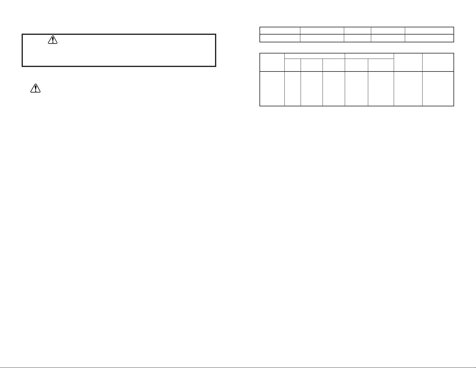
SPECIFICATIONS
Typical Flow, Pressure and Vacuum Data:
L/S
®
Flow rate (cw) Discharge Pressure* Vacuum* Suction Lift*
Tubing @ 1 rpm @ 100 rpm @ 600 rpm Continuous Intermittent @ 600 rpm @ 600 rpm
mL/min mL/min mL/min psig (bar) psig (bar) in (mm) Hg ft (m) H
2
0
L/S
®
16HP** .9 90 — 100 (6.8) 125 (8.5) — —
L/S
®
15HP** 1.7 170 — 80 (5.5) 100 (6.8) — —
L/S
®
15 1.8 — 1100 25 (1.7) 40 (2.7) 26 (660) 29 (8.8)
L/S
®
24 3.0 — 1800 25 (1.7) 40 (2.7) 26 (660) 29 (8.8)
L/S
®
35 4.3 — 2600 20 (1.4) 35 (2.4) 26 (660) 29 (8.8)
L/S
®
36 5.8 — 3400 15 (1.0) 20 (1.4) 24 (610) 27 (8.3)
Number of rollers: 3
Occlusion: Fixed
Maximum pump speed (rpm): 600
Nominal torque load—Running: up to 180 oz-in (13 kg•cm)
Housing materials: Stainless steel (SS), polyester (PE) body,
polyphenylene sulfide (PPS) tubing bed,
polypropylene (PP) knob
Roller/bearing materials: Stainless Steel (SS)/Sealed Stainless Steel
Rotor materials: Stainless Steel (SS)
Operating Temperature
‡
: 32°F to 104°F (0°C to 40°C)
Storage Temperature: –40°F to 149°F (–40°C to 65°C)
Humidity: 5% to 95% (non-condensing)
Dimensions (W
3H 3
D):
Operating: 3.7 in
3
3.5 in 33.0 in (94 mm 389 mm 376 mm)
Open: 4.5 in
3
3.5 in 35.1 in (114 mm 3 89 mm 3130 mm)
Weight: 2.1 lb (0.96 kg)
* As tested with NORPRENE®, PHARMED®, and TYGON®tubing.
Values will be less with silicone and C-FLEX
®
.
**L/S
®
15HP and L/S® 16HP tubing are for use only with the MASTERFLEX®L/S®High-Performance Pump Head
and any MASTERFLEX
®
L/S®1 to 100 rpm drive capable of running two or more pump heads.
‡ Use in this temperature range for continuous duty operation with no decrease in performance or product life.
Pump heads will work outside this range with some possible reductions in performance or product life.
C-FLEX — Reg TM Consolidated Polymer Technologies, Inc.
NORPRENE, PHARMED, TYGON — Reg TM Norton Co.
Trademarks bearing the ® symbol in this publication
are registered in the U.S. and in other countries.
Pump Head Number Pump Material Occlusion Shaft Length L/S®Tubing
77250-62 PPS/PE/SS Fixed Short L/S
®
15, 24, 35, 36
SAFETY PRECAUTIONS
Page 3

Loading Tubing
WARNING: Turn off drive before removing or installing tubing.
Fingers or loose clothing could be caught in the rollers.
1. Rotate tubing retainer knob, Figure 2, counterclockwise to release retainer,
then pull to open cover.
2. Lift latch to open occlusion bed.
Figure 2. High-Performance Pump Head
INTRODUCTION
The MASTERFLEX®L/S®High-Performance Pump Head delivers in excess of
3 L/min flow at normal MASTERFLEX operating speeds and pressures. It is
designed for optimal pumping in the clockwise direction. There are two mounting
positions. Tubing entry and exit are either on the left side or on top of the pump
when mounted on a MASTERFLEX
®
L/S®Drive. The pump will operate with any
MASTERFLEX
®
L/S®drive with 180 oz-in (13 kg•cm) or more output torque.
SETUP AND OPERATION
Pump Drive Compatibility
The High-Performance Pump Head has a standard shaft interface to
accommodate MASTERFLEX
®
L/S®Pump Drives. Pump drive must provide
180 in-oz (13 kg•cm) torque. (NOTE: These drives are usually designated as
capable of driving two or more pump heads.)
Mounting Pump Head to Drive
1. Check that pump drive is turned OFF.
2. Align pump shaft tang with slot in motor shaft.
3. If pump drive has alignment pins, slide pump head alignment holes over
pins.
4. Secure pump to pump drive with the two mounting screws (furnished).
a. For left side tubing entry and exit, use round mounting holes.
(Labeled "A" in Figure 1.)
b. For top tubing entry and exit, use hexagonal mounting holes.
(Labeled "B" in Figure 1.)
Selecting Tubing
Pumps accept only L/S®15, L/S®24, L/S®35 and L/S®36 tubing. Use only
MASTERFLEX tubing that is surface-printed with the tubing designation.
4
5
Figure 1. Mounting Holes
A
A
B
B
Page 4

3. Insert the MASTERFLEX tubing inside tubing guide and around rotor with the
ends of the tubing extending out of the tubing entrance and tubing exit as
shown in Figure 3. Center tubing on roller.
4. Press the occlusion bed against the tubing, and snap the latch closed.
5. Close the cover, then pull the tubing snug (do not stretch) around the rotor
assembly. Tighten the tubing retainer by rotating the tubing retainer knob
clockwise sufficiently to prevent the tube from moving. Pump is now ready
for operation.
Figure 3. Loading Tubing
Operation
1. Connect pump tubing to desired source and destination.
2. Start pump drive and set desired speed.
MAINTENANCE
Maintenance is limited to replacement of the parts listed in the replacement
parts list and cleaning the pump head.
Replacement Parts
REF DESCRIPTION ORDER NUMBER
A Rotor Assembly with Clip 77250-69
B Tubing Retainer Kit 77250-66
C Occlusion Bed Assembly Kit 77250-67
D Mounting Screws (not shown) 77250-01
Figure 4. Exploded View of Pump
Cleaning Pump Head
Use mild detergent with water to clean the pump and rotor assembly. Do not
immerse nor use excessive fluid.
6
7
A
B
C
 Loading...