

Page 1
OPERATING MANUAL
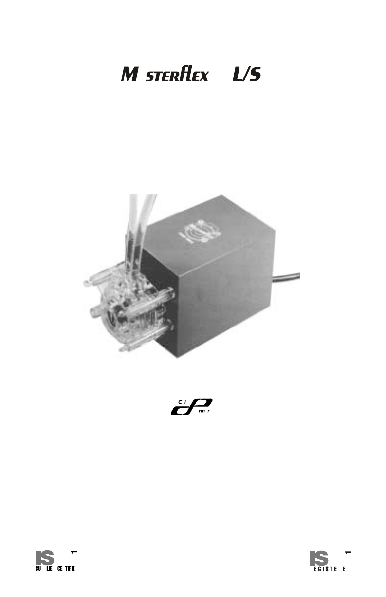
FIXED FLOW PUMP DRIVES
Model Nos.
7543-01 7543-30 7544-12
7543-02 7543-60 7544-20
7543-06 7544-01 7544-30
7543-12 7544-02 7544-60
7543-20 7544-06
Note: Pump is shown with optional Pump Head.
®
Cole-Parmer Instrument Co.
1-800-MASTERFLEX (627-8373) (U.S. and Canada only)
11 (847) 549-7600 (outside U.S.)
(847) 549-7600 (Local)
www.masterflex.com
Barnant Company
1-800-637-3739 (U.S. and Canada only)
11 (847) 381-7050 (outside U.S.)
(847) 381-7050 (Local)
www.barnant.com
A-1299-0597
Edition 05
Page 2
EU Declaration of Conformity
Name of Apparatus: MASTERFLEX® L/S® Fixed-Speed Drive
Model Numbers: 7544-01, -02, -06, -12, -20, -30, -60
Description of Apparatus: Peristaltic Pump Motor Drive. Used with
Pump Head and Peristaltic Tubing to pump
fluids.
7544-01 (1 rpm), -02 (2 rpm), -06 (6 rpm);
7544-12 (12 rpm), -20 (20 rpm);
7544-30 (30 rpm), -60 (60 rpm)
Barnant Company declares that the above models are in
conformity to the following harmonized standards and directives:
Applicable Applicable Manufacturer’s
Directives Specifications Report Number
73/23/EEC EN61010-1/A2: 1995 TR9530
93/68/EEC
89/336/EEC EN61326-1/A1: 1998 TR9531
92/31/EEC
93/68/EEC
The last two digits of the year in which the current configuration
of the above models was assessed per the Lo w V oltage Directive
is: 00.
Manufacturer: Barnant Company Division
Cole-Parmer Instrument Company
28W092 Commercial Aven ue
Barrington, IL 60010-2392
USA
T el.: 847-381-7050
Manufacturer’s Signature:
16 August, 2000
James W. Doll Date
Vice President, Engineering
2
Page 3
TABLE OF CONTENTS
Title Page
SAFETY PRECAUTIONS ......................................................................... 3
INTRODUCTION AND GENERAL DESCRIPTION .................................. 4
SETUP AND OPERATION........................................................................ 4
MAINTENANCE ........................................................................................ 5
Cleaning ................................................................................................ 6
Replacement Parts ............................................................................... 6
Gear/Motor Assembly Replacement Instructions.................................. 6
SPECIFICATIONS .................................................................................... 6
WARRANTY.............................................................................................. 8
PRODUCT RETURN ................................................................................. 8
TECHNICAL ASSISTANCE ...................................................................... 8
SAFETY PRECAUTIONS
WARNINGS: Remove power from the drive before attempting any
maintenance.
Remove power before any cleaning operation is started.
WARNINGS: Tubing breakage may result in fluid being sprayed
from pump. Use appropriate measures to protect operator and equipment.
Turn drive off before removing or installing tubing.
Fingers or loose clothing could be caught in the drive
mechanism.
WARNING: PRODUCT USE LIMITATION
These products are not designed for, nor intended for use in,
patient-connected applications, including, but not limited to , medical and dental use, and, accordingly, have not been submitted for
FDA approval.
Trademarks bearing the ® symbol in this publication are registered in the U.S. and in other countries.
3
Page 4

INTRODUCTION AND GENERAL DESCRIPTION
The MASTERFLEX® L/S® fixed flow drives provide continuous fixed speed
pumping of fluids while power is supplied.
Different models provide various speeds as summarized:
Pump Heads
Model# Description Speed (rpm) Accepted
7543-01 L/S Fixed Speed, 115V AC, 60 Hz 1 2
7543-02 L/S Fixed Speed, 115V AC, 60 Hz 2 2
7543-06 L/S Fixed Speed, 115V AC, 60 Hz 6 2
7543-12 L/S Fixed Speed, 115V AC, 60 Hz 12 2
7543-20 L/S Fixed Speed, 115V AC, 60 Hz 20 2
7543-30 L/S Fixed Speed, 115V AC, 60 Hz 30 2
7543-60 L/S Fixed Speed, 115V AC, 60 Hz 60 1
7544-01 L/S Fixed Speed, 230V AC, 50 Hz 1 x (5/6)* 2
7544-02 L/S Fixed Speed, 230V AC, 50 Hz 2 x (5/6)* 2
7544-06 L/S Fixed Speed, 230V AC, 50 Hz 6 x (5/6)* 2
7544-12 L/S Fixed Speed, 230V AC, 50 Hz 12 x (5/6)* 2
7544-20 L/S Fixed Speed, 230V AC, 50 Hz 20 x (5/6)* 2
7544-30 L/S Fixed Speed, 230V AC, 50 Hz 30 x (5/6)* 2
7544-60 L/S Fixed Speed, 230V AC, 50 Hz 60 x (5/6)* 1
*Note: Reflects operation at 50 Hz.
SETUP AND OPERATION
Use only MASTERFLEX precision tubing with MASTERFLEX pumps
to ensure optimum performance.
Use of other tubing may void applicable warranties.
Unpack the drive and retain all packing material until proper product operation
has been verified. Select the pump head and tubing according to the flow
desired, while considering chemical compatibility and tubing life. Pump installation instructions are included with the pump head. Connect the line cord to a
grounded three-wire AC receptacle to activate the pump drive.
4
Page 5

The following sketch shows the dimensional outline of the drive:
MAINTENANCE
WARNING: Remove power from the drive before attempting any
maintenance.
The rear motor bearing should be given two drops of #20 non-detergent oil
every three months. Do not over oil. Clean off any accumulated dust or dirt.
The drive gear/motor assembly can be replaced if necessary. Exact “life” will
depend on the number of heads and the speed used.
REAR MOTOR BEARING
OR
HUB FACINGMTR.
AIR FLOW
5
Page 6

Cleaning
WARNING: Remove power before any cleaning operation is started.
Keep the drive enclosure clean by using a mild detergent solution. Never immerse or use excessive fluid when cleaning the drive.
Replacement Parts
Drive Model # Gear/Motor Assembly
7543-01 D - 1562 - 1
7543-02 D - 1562 - 2
7543-06 D - 1562 - 3
7543-12 D - 1562 - 4
7543-20 D - 1562 - 5
7543-30 D - 1562 - 6
7543-60 D - 1562 - 7
7544-01 D - 1562 - 8
7544-02 D - 1562 - 9
7544-06 D - 1562 - 10
7544-12 D - 1562 - 11
7544-20 D - 1562 - 12
7544-30 D - 1562 - 13
7544-60 D - 1562 - 14
Gear/Motor Assembly Replacement Instructions
Disconnect power from the drive. Remove pump assembly if attached. Remove cover. Disconnect power and ground wires from power cord to motor.
Remove gear/motor assembly from mounting plate. Install new gear/motor
assembly to mounting plate. Connect power and ground wires from cord to
motor. Be sure ground wire is attached to chassis. Reinstall cov er. Apply po wer
to test unit. Attach pump to drive.
SPECIFICATIONS
Output:
Model# Speed Torque Pump Heads Current
(rpm) (in-oz) (kg-cm) (Amps)
7543-01 1 224 16 2 .5
7543-02 2 224 16 2 .5
7543-06 6 224 16 2 .6
7543-12 12 224 16 2 .6
7543-20 20 208 15 2 1.2
7543-30 30 224 16 2 1.2
7543-60 60 112 8 1 1.2
6
Page 7

Model# Speed Torque Pump Heads Current
(rpm) (in-oz) (kg-cm) (Amps)
7544-01 1 x (5/6)* 224 16 2 .25
7544-02 2 x (5/6)* 224 16 2 .25
7544-06 6 x (5/6)* 224 16 2 .3
7544-12 12 x (5/6)* 224 16 2 .3
7544-20 20 x (5/6)* 208 15 2 .6
7544-30 30 x (5/6)* 224 16 2 .6
7544-60 60 x (5/6)* 112 8 1 .6
*Note: Speed for the 7544 series drives is 5/6 that of the 7543
series due to operation at 50 Hz.
Input:
Operating V oltage/F requency:
7543 Series 115V AC ± 10%, 60 Hz
7544 Series 230V AC ± 10%, 50 Hz
Installation Category: Installation category II per IEC 664
(local level—appliances , portable
equipment, etc.)
Environment:
Operating Temperature: 0°C to 40°C
Storage Temperature: –45°C to 65°C
Humidity: 10% to 90% non-condensing
Altitude: Less than 2000 meters
Pollution Degree: Pollution degree 2 per IEC 664
(indoor usage—lab,office)
Construction:
Dimensions (L x W x H): 15.1 cm x 10.2 cm x 11.1 cm
(6 in x 4 in x 4.4 in)
Weight: 2.3 kgs (5.1 lbs)
Color: Gray and black
Material: Painted steel housing
Enclosure Rating: IP21 per IEC 529
Compliance: 230V (For CE Mark):
EN61010-1/A2: 1995
(EU Low Voltage Directive) and
EN61326-1/A1: 1998 (EU EMC Directive)
7
Page 8

WARRANTY
Use only MASTERFLEX precision tubing with MASTERFLEX pumps to
ensure optimum performance. Use of other tubing may void applicable
warranties.
The Manufacturer warr ants this product to be free from significant deviations
from published specifications. If repair or adjustment is necessary within the
warranty period, the problem will be corrected at no charge if it is not due to
misuse or abuse on your part as determined by the Manufacturer. Repair
costs outside the warranty period, or those resulting from product misuse or
abuse, may be invoiced to you.
The warranty period for this product is noted on the Warranty Card.
PRODUCT RETURN
To limit charges and delays, contact the seller or Manufacturer for authorization and shipping instructions before returning the product, either within or
outside of the warranty period. When returning the product, please state the
reason for the return. For your protection, pack the product carefully and insure it against possible damage or loss. Any damages resulting from improper
packaging are your responsibility.
TECHNICAL ASSISTANCE
If you have an y questions about the use of this product, contact the Manuf acturer or authorized seller.
Cole-Parmer Instrument Co.
625 East Bunker Court
Vernon Hills, Illinois U .S.A. 60061-1844
1-800-MASTERFLEX (627-8373) (U.S. and Canada only)
11 (847) 549-7600 (outside U.S.)
(847) 549-7600 (Local)
FAX (847) 247-2929 (U .S . and Canada only)
11 (847) 549-1700 (Fax outside U .S.)
www.masterflex.com
e-mail: techinfo@coleparmer .com
Barnant Company
28W092 Commercial Ave.
Barrington, Illinois U.S.A. 60010-2392
1-800-637-3739 (U.S. and Canada only)
11 (847) 381-7050 (outside U.S.)
(847) 381-7050 (Local)
11 (847) 381-7053 (Fax outside U .S.)
(847) 381-7053 (Local Fax)
www.barnant.com
e-mail: barnant@barnant.com
8
Printed in U.S.A.
041000
 Loading...