

Page 1
®
®®
Operating Manual:
L/S® & I/P® DIGITAL PUMP
DRIVES WITH ETHERNET I/P
™
QF150 & QF1200
Model No.
74000-49
Model 74000-51
74000-51
74000-53
74000-59
Model 74000-59
(US & Canada only) Toll Free 1-800-MASTERFLEX • 1-800-637-3739
(Outside US & Canada) 1-847-549-7600 • 1-847-381-7050
www.masterflex.com • techinfo@masterflex.com
Edition 03
A-1299-7357
Page 2

Preface
© 2020 Cole-Parmer Instrument Company. All rights reserved.
Masterflex – Reg TM Cole-Parmer Instrument Company.
Trademarks bearing the ® symbol in this publication are registered in the U.S. and in other countries.
ORIGINAL INSTRUCTIONS
PUMP FOR LIQUIDS
MASTERFLEX® Digital Pump Drive Operating Manual
ii
Masterflex
Page 3

Preface
Explanation of Symbols
SAFETY
PRECAUTIONS
DANGER: High voltages exist and are accessible. Use extreme
caution when servicing internal components.
WARNINGS: Do not operate the pump drive in a manner not
specified in the documentation. Misuse of the pump drive may result
in a hazard and may compromise the safety protection built into the
pump drive. If the pump drive is damaged, turn it off and not use it until
service-trained personnel can check its safety.
Single-Phase Only. Not to be used with Split-Phase lines.
The Power switch on the Back Panel is not the main disconnect. Main
disconnect is accomplished by disconnecting the detachable power
supply cord at the appliance coupler or at the main plug. Ensure the
power cord is easily accessible and removable, in the event of an
emergency, which requires immediate disconnection.
The operator should check the detachable power supply cord
condition. The equipment should not be operated if the power supply
cord is cracked or broken. Any obvious damage to the enclosure (from
a drop or fall) should be checked by service personnel for loose or
damaged parts inside.
CAUTIONS: Power must be turned off before connecting the external
!
remote control cable to prevent damage to the drive.
Do not block the rear panel of the Pump Drive. The power switch must
always be easy to access. The power cord must always be easy to
disconnect.
Replace the power cord only with one of the same type and
rating. The minimum power ratings are stated on the rear panel.
The power cord set supplied with your pump drive meets the
requirements of the country where you purchased the pump drive. If
you use the pump drive in another country, you must use a power cord
set that meets the requirements of that country.
When using hazardous chemical and biological agents, take all
suitable protective measures, such as wearing protective glasses and
gloves resistant to the substances used. Follow local and/or national
regulations for safe operation and maintenance of the system.
CAUTION: To avoid electrical shock, the power cord protective
grounding conductor must be connected to ground. Not for
operation in wet locations as defined by EN61010-1.
CAUTIONS: Keep fingers away from coupling while pump is in
operation.
MASTERFLEX® Digital Pump Drive Operating ManualMasterflex
iii
Page 4

Preface
Explanation of Symbols
Explanation of
Symbols
WARNING:
Product Use
Limitation
CAUTION: Risk of Danger. Consult Operator’s manual for nature
!
of hazard and corrective actions.
CAUTION: Risk of injury. Keep fingers away from the coupling
while shaft is rotating. Do not operate without Pump Head
installed.
CAUTION: Hot Surface. Do not touch.
CAUTION: Risk of electric shock. Consult Operator’s manual for
nature of hazard and corrective actions.
This product is not designed for, nor intended for use in patient
!
connected applications; including, but not limited to, medical and
dental use, and accordingly has not been submitted for FDA approval.
This product is not designed for, nor intended for use in hazardous
duty areas as defined by ATEX or the NEC (National Electrical Code);
including, but not limited to use with flammable liquids. Consult the
factory for products suitable for these types of applications
MASTERFLEX® Digital Pump Drive Operating Manual
Masterflex
Page 5

Table of Contents
Contents
Page
Section 1
Section 2 INSTALLATION AND SETUP . . . . . . . . . . . . . . . . . . . . . . . . . . . . . . . . . . . .2-1
Section 3
INTRODUCTION . . . . . . . . . . . . . . . . . . . . . . . . . . . . . . . . . . . . . . . . . . . . . .
General Description . . . . . . . . . . . . . . . . . . . . . . . . . . . . . . . . . . . . . . . . . . . . . .1-1
Before Starting the Drive . . . . . . . . . . . . . . . . . . . . . . . . . . . . . . . . . . . . . . . . .
Mounting the Pump Head . . . . . . . . . . . . . . . . . . . . . . . . . . . . . . . . . . . . . . . .
OPERATION . . . . . . . . . . . . . . . . . . . . . . . . . . . . . . . . . . . . . . . . . . . . . . . . . .
Turning On the Drive . . . . . . . . . . . . . . . . . . . . . . . . . . . . . . . . . . . . . . . . . . . .
Control Panel . . . . . . . . . . . . . . . . . . . . . . . . . . . . . . . . . . . . . . . . . . . . . . . . . .
Priming the Pump . . . . . . . . . . . . . . . . . . . . . . . . . . . . . . . . . . . . . . . . . . . . . .
Main Menu . . . . . . . . . . . . . . . . . . . . . . . . . . . . . . . . . . . . . . . . . . . . . . . . . . .
Pump Head Calibration . . . . . . . . . . . . . . . . . . . . . . . . . . . . . . . . . . . . . . . . . . .
Setup Menu . . . . . . . . . . . . . . . . . . . . . . . . . . . . . . . . . . . . . . . . . . . . . . . . . . . .
Continuous Mode Screen . . . . . . . . . . . . . . . . . . . . . . . . . . . . . . . . . . . . . . . . .
Continuous Mode Operation . . . . . . . . . . . . . . . . . . . . . . . . . . . . . . . . . . . . . .
Time Dispense Mode Screen . . . . . . . . . . . . . . . . . . . . . . . . . . . . . . . . . . . . . .
Time Dispense Mode Operation . . . . . . . . . . . . . . . . . . . . . . . . . . . . . . . . . . .
Copy Dispense Mode Screen . . . . . . . . . . . . . . . . . . . . . . . . . . . . . . . . . . . . .
Copy Dispense Mode Operation . . . . . . . . . . . . . . . . . . . . . . . . . . . . . . . . . . .
COPY Setting Screen . . . . . . . . . . . . . . . . . . . . . . . . . . . . . . . . . . . . . . . . . . . .
COPY Setting Operation . . . . . . . . . . . . . . . . . . . . . . . . . . . . . . . . . . . . . . . . .
Volume Dispense Mode Screen . . . . . . . . . . . . . . . . . . . . . . . . . . . . . . . . . . .
Volume Dispense Mode Operation . . . . . . . . . . . . . . . . . . . . . . . . . . . . . . . . .
Remote Control Menu . . . . . . . . . . . . . . . . . . . . . . . . . . . . . . . . . . . . . . . . . . .
31- Pin Configuration with Wiring Scheme . . . . . . . . . . . . . . . . . . . . . . . . . . .
Remote Control Inputs and Outputs . . . . . . . . . . . . . . . . . . . . . . . . . . . . . . . .
Open Collector Outputs . . . . . . . . . . . . . . . . . . . . . . . . . . . . . . . . . . . . . . . . . .
Communication Specifications . . . . . . . . . . . . . . . . . . . . . . . . . . . . . . . . . . . .
Get Commands . . . . . . . . . . . . . . . . . . . . . . . . . . . . . . . . . . . . . . . . . . . . . . . . .
ASCII Control Codes . . . . . . . . . . . . . . . . . . . . . . . . . . . . . . . . . . . . . . . . . . . . .
Set Commands . . . . . . . . . . . . . . . . . . . . . . . . . . . . . . . . . . . . . . . . . . . . . . . . .
Dispense Commands . . . . . . . . . . . . . . . . . . . . . . . . . . . . . . . . . . . . . . . . . . . .
Command Summary . . . . . . . . . . . . . . . . . . . . . . . . . . . . . . . . . . . . . . . . . . . . .
1-1
2-1
2-1
3-1
3-1
3-2
3-2
3-3
3-4
3-6
3-7
3-8
3-9
3-10
3-12
3-13
3-15
3-16
3-17
3-18
3-20
3-23
3-24
3-25
3-26
3-28
3-32
3-33
3-35
3-38
MASTERFLEX® Digital Pump Drive Operating ManualMasterflex
v
Page 6

Table of Contents
Table of Contents
(continue)
Section 4 MAINTENANCE . . . . . . . . . . . . . . . . . . . . . . . . . . . . . . . . . . . . . . . . . . . . . . .4-1
Replacement Parts and Accessories . . . . . . . . . . . . . . . . . . . . . . . . . . . . . . . .
Fuse Replacement . . . . . . . . . . . . . . . . . . . . . . . . . . . . . . . . . . . . . . . . . . . . . .
Cleaning . . . . . . . . . . . . . . . . . . . . . . . . . . . . . . . . . . . . . . . . . . . . . . . . . . . . . .
Section 5
Section 6 ACCESSORIES . . . . . . . . . . . . . . . . . . . . . . . . . . . . . . . . . . . . . . . . . . . . . . .
Section 7 SPECIFICATIONS . . . . . . . . . . . . . . . . . . . . . . . . . . . . . . . . . . . . . . . . . . . . . 7-1
Section 8 PRODUCT ASSISTANCE . . . . . . . . . . . . . . . . . . . . . . . . . . . . . . . . . . . . . . . 8-1
TROUBLESHOOTING . . . . . . . . . . . . . . . . . . . . . . . . . . . . . . . . . . . . . . . . . .
Troubleshooting Chart . . . . . . . . . . . . . . . . . . . . . . . . . . . . . . . . . . . . . . . . . . .
Error Definitions . . . . . . . . . . . . . . . . . . . . . . . . . . . . . . . . . . . . . . . . . . . . . . . .
Product Return . . . . . . . . . . . . . . . . . . . . . . . . . . . . . . . . . . . . . . . . . . . . . . . . .8-1
Page
4-1
4-2
4-2
5-1
5-1
5-2
6-1
8-1Technical Assistance . . . . . . . . . . . . . . . . . . . . . . . . . . . . . . . . . . . . . . . . . . . .
MASTERFLEX® Digital Pump Drive Operating Manual
vi
Masterflex
Page 7

Figures
Page
Control Panel . . . . . . . . . . . . . . . . . . . . . . . . . . . . . . . . . . . . . . . . . . . . . . . . . 3-2
3-7Continuous Mode Screen . . . . . . . . . . . . . . . . . . . . . . . . . . . . . . . . . . . . . . . .
Continuous Mode Operation . . . . . . . . . . . . . . . . . . . . . . . . . . . . . . . . . . . . . .3-8
3-9Time Dispense Mode Screen . . . . . . . . . . . . . . . . . . . . . . . . . . . . . . . . . . . . .
Time Dispense Mode Operation . . . . . . . . . . . . . . . . . . . . . . . . . . . . . . . . . . . 3-10
Copy Dispense Mode Screen . . . . . . . . . . . . . . . . . . . . . . . . . . . . . . . . . . . . .
Copy Dispense Mode Operation . . . . . . . . . . . . . . . . . . . . . . . . . . . . . . . . . . .3-13
COPY Setting Operation . . . . . . . . . . . . . . . . . . . . . . . . . . . . . . . . . . . . . . . . . 3-16
Volume Dispense Mode Screen . . . . . . . . . . . . . . . . . . . . . . . . . . . . . . . . . . .
Volume Dispense Mode Operation . . . . . . . . . . . . . . . . . . . . . . . . . . . . . . . . .3-18
Remote Control Menu Screen . . . . . . . . . . . . . . . . . . . . . . . . . . . . . . . . . . . .
31-Pin Configuration with Wiring Scheme . . . . . . . . . . . . . . . . . . . . . . . . . . 3-23
terminating Open Collector Outputs to a PLC . . . . . . . . . . . . . . . . . . . . . . . .
Fuse Replacement . . . . . . . . . . . . . . . . . . . . . . . . . . . . . . . . . . . . . . . . . . . . . .4-2
3-12
3-15COPY Setting Screen . . . . . . . . . . . . . . . . . . . . . . . . . . . . . . . . . . . . . . . . . . .
3-17
3-20
3-25
MASTERFLEX® Digital Pump Drive Operating ManualMasterflex
vii
Page 8

Page 9

Tables
Page
Nominal Calibration Volumes . . . . . . . . . . . . . . . . . . . . . . . . . . . . . . . . . . . . .3-5
Continuous Mode Operation . . . . . . . . . . . . . . . . . . . . . . . . . . . . . . . . . . . . . .3-22
3-22Dispense Mode Operation . . . . . . . . . . . . . . . . . . . . . . . . . . . . . . . . . . . . . . .
Remote Control Inputs and Outputs . . . . . . . . . . . . . . . . . . . . . . . . . . . . . . . . 3-24
ASCII Control Codes . . . . . . . . . . . . . . . . . . . . . . . . . . . . . . . . . . . . . . . . . . . .3-32
Command Summary . . . . . . . . . . . . . . . . . . . . . . . . . . . . . . . . . . . . . . . . . . . .3-39
MASTERFLEX® Digital Pump Drive Operating ManualMasterflex
ix
Page 10

Page 11

Section 1 Introduction
Welcome to the Masterfl ex Digital Pump Drive. is drive has many of
the same functions as the standard MASTERFLEX L/S® Digital Drive for
peristaltic pumps. With Diff erent Pump Heads the system off ers fl ow rates
from 5 to 14, 230 mL/min.
General Description
e Masterfl ex Digital Drive provides a motor speed repeatability of 0.1
percent to maximize productivity in precision liquid dosing, batch dispensing
and fi lling applications. A turndown ratio up to 600-to-1, self-priming capab
iliti es allow for smooth, seamless operation and an extremely broad fl ow
range.
In addition to high accuracy, precision, repeatability and resolution of speed
(or fl ow rate), the Masterfl ex Drive features a multi-language, intuitive, man/
machine interface with a four-line graphical LCD display providing direct
readout of pump speed (rpm), fl ow rate (user-selected units), number of
dispenses, and menu options.
e easy-to-use keypad eliminates setpoint overshoot and provides easy
navigation through menu options that include a number of on-screen
programming features.
is Masterfl ex Drive with its high turndown, superior accuracy, and intuitive
interface make it ideally suited where precise and repeatable fl ow control is
required. e pump accommodates a variety of product fi ll volumes and batch
dispensing profi les.
MASTERFLEX® Digital Pump Drive Operating ManualMasterflex
1-1
Page 12

Page 13

Section 2 Installation and Setup
Before Starting Drive
• The drive should be mounted on a flat horizontal surface, and no
more than two (2) Pump Heads should be added for 600 rpm drives
or four (4) Pump Heads for 100 rpm drives.
• The ambient air temperature should not exceed 104° F (40° C) and
adequate air flow should be provided for.
CAUTION: Do not block the rear panel of the pump drive. The power
!
switch must always be easy to access. The power cord must always
be easy to disconnect.
• Tubing should be clean and routed so that bend radii are at a
minimum four (4) times the tube diameter and as short as possible.
WARNING: Turn drive off before removing or installing tubing. Fingers
!
or loose clothing could get caught in drive mechanism.
• Use a tube size of appropriate diameter for the flow rate and
viscosity required.
• To maintain the best accuracy of flow rates, re-calibrate pump heads
regularly. See Pump Head Calibration Section of this manual.
• For tubing selection and compatibility, see Tubing Selection Guide
within this flash drive or on the web.
• For Pump Head information, see Pump Head datasheets within this
flash drive or on the web.
• When cleaning or performing maintenance, please remove power from
the drive.
CAUTION: The power cord set supplied with your pump drive meets the
!
requirements of the country where you purchased the pump drive.
If you use the pump drive in another country, you must use a power
cord set that meets the requirements of that country.
DANGER: High voltages exist and are accessible. Use extreme caution
when servicing internal components.
MASTERFLEX® Digital Pump Drive Operating ManualMasterflex
2-1
Page 14

Section 2
Installation and Setup
Mounting the
Pump Head
• Mount Pump Head and load tubing (See Pump Head information
within this flash drive or on the web). Check to make sure that rollers
are clean and free of defects.
CAUTION: When using hazardous chemical and biological agents,
take all suitable protective measures, such as wearing protective
!
glasses and gloves resistant to the substances used. Follow local
and/or national regulations for safe operation and maintenance of
the system.
MASTERFLEX® Digital Pump Drive Operating Manual2-2
Masterflex
Page 15

Section 3 Operation
Turning on the Drive
WARNING: Do not operate the pump drive in a manner not specified
in the documentation. Misuse of the pump drive may result in a
hazard and may compromise the safety protection built into the
pump drive. If the pump drive is damaged, turn it off and not use it
until service-trained personnel can check its safety.
1. Plug the power cord into the IEC Connector, located on the rear of
the drive. Plug the opposite end of the power cord into an electrical
outlet.
2. Flip the power switch located on the rear of the drive.
3. Upon turning on the drive for the first time you will be prompted to
select a language. The selected language will be set as the default but
can be changed at any time by selecting “LANGUAGE” on the main
menu.
4. After selecting your language, the Main Menu will now appear on the
LCD screen. (NOTE: Each start-up after the initial will revert to the
mode of operation screen previously in use.)
5. If the language is accidently changed and the user would like to reset
it to the default language (English), press and hold the UP/DOWN
(s/t) keys during power up.
6. To restore drive to default settings, press and hold the LEFT/RIGHT
(s/s) keys during power up.
CAUTION: To avoid electrical shock, the power cord protective
grounding conductor must be connected to ground. Not for operation
in wet locations as defined by EN61010-1.
CAUTION: Power must be turned off before connecting the external
!
remote control cable to prevent damage to the drive.
MASTERFLEX® Digital Pump Drive Operating ManualMasterflex
3-1
Page 16
Section 3
Operation
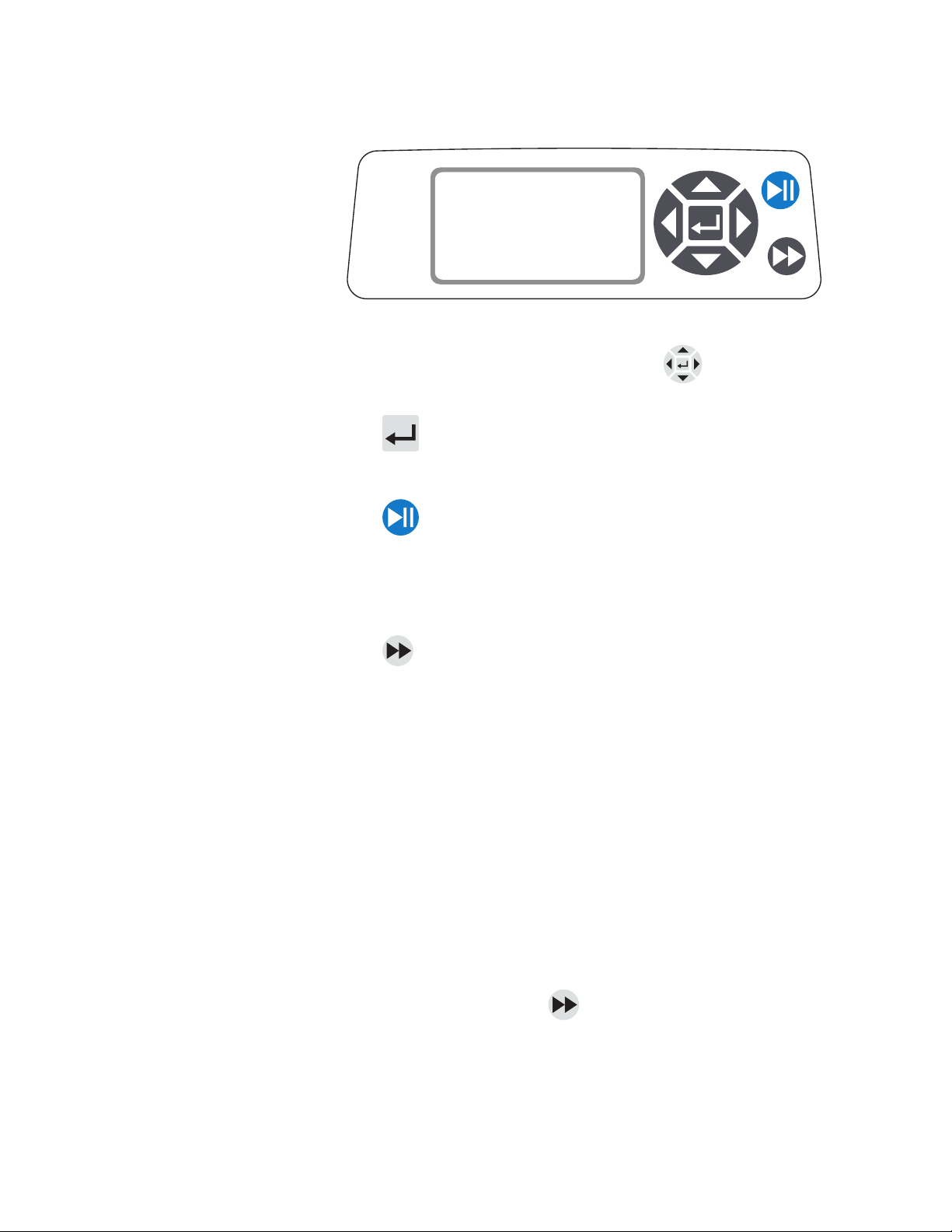
Control Panel
Figure 3-1. Control Panel
Priming the Pump
• To navigate all menus on the drive use the
directional pad directly to
the right of the LCD screen.
• The
(ENTER) key located in the middle of the directional pad is
used to enter or select a highlighted field or option. This key is often
referred to as the ENTER key in this manual.
• The
(START/STOP) key located at the top right of the control panel
is used to start and pause the drive. This key is functional only when in one
of the four operating modes: Continuous, Time Dispense, Copy Dispense,
or Volume Dispense. This key is often referred to as the START/STOP
key in this manual.
• The
(PRIME) key located at the bottom right of the control panel is
used to access the prime (fast forward) function. While pressed, this key
operates the drive at the maximum allowed speed/flow rate and in the
direction shown on the display. When released, the drive returns to its
original speed or flow rate.
1. Mount Pump Head to drive.
2. Insert appropriate tubing into Pump Head.
3-2
MASTERFLEX® Digital Pump Drive Operating Manual
3. Insert tube inlet into supply fluid.
4. Insert supply outlet into desired container.
5. Turn on pump using switch located on the back of the drive.
6. Press and hold the PRIME
key on the drive console to prime the
pump. Priming will stop when key is released.
CAUTION: Keep fingers away from rotor while pump is in operation.
Stop pump before loading or unloading tubing.
Masterflex
Page 17

Section 3
Operation
Main Menu
CONTINUOUS MODE refer to Continuous Mode in this manual.
TIME DISPENSE MODE refer to Time Dispense Mode in this manual.
COPY DISPENSE MODE refer to Copy Dispense Mode section in this
manual.
VOLUME DISPENSE MODE refer to Volume Dispense Mode section in
this manual.
REMOTE CONTROL MODE refer to Remote Control Mode section in
this manual.
CUMULATIVE VOLUME: The drive stores and displays the cumulative
volume in units based on flow rate units (see SETUP MENU in this
section). The Cumulative Volume can also be reset to zero.
NOTE: The Cumulative Volume is dependent on the Tubing Size selected.
(See SETUP MENU in this section.)
SOUNDS: An audible “beep” can be enabled to indicate a keypad press,
the end of a dispense and/or the end of a batch.
AUTOSTART: By default the drive will not restart when power is
applied. To enable this feature select AUTOSTART and then ON. The
drive will now restart when power is reapplied.
DISPLAY CONTRAST: This display can be adjusted using the UP/
DOWN (s/t) arrows after selecting this menu item.
LANGUAGE: After selecting this menu, the user will be able to select one
of seven different languages.
NOTE: If the language is accidentally changed and the user would like to
reset it to the default language (English), press and hold the UP/DOWN
(s/t) keys when power is reapplied.
DEFAULT SETTINGS: Selecting this menu item and pressing the
ENTER key will restore default settings. To restore drive to default
settings the user may also press and hold the LEFT/RIGHT
(s/s) keys
when power is reapplied.
MASTERFLEX® Digital Pump Drive Operating ManualMasterflex 3-3
Page 18

Section 3
Operation
Pump Head
Calibration
1. Mount Pump Head to drive.
2. Connect suction and discharge to Pump Head.
3. Follow Pump Head instructions for priming pump.
4. Container should be a graduated container or a container placed on a scale may be
used for increased accuracy.
If using a scale, an acceptable weight to volume conversion for water is
1 gram =1mL.
5. Turn on drive using power switch located on the rear of the drive.
6. Go to the Main Menu or Mode Setup Menu by selecting the SETUP icon
pressing the ENTER key. Use the UP and DOWN keys to highlight CAL in the
Main or Setup Menu and press the ENTER key.
7. Set the drive for the desired flow direction, Pump Head, and flow rate. Note that
these settings are retained and transferred to other mode screens when entering or
leaving the CAL screen.
The Pump Head is set using the directional keypad to highlight the Pump Head
field. Press ENTER and use the UP/DOWN keys to select the Pump Head size
Press ENTER to SAVE the selection and return to CAL screen.
and
The estimated flow rate is set using the directional keypad to highlight the flow rate
field. Press ENTER and use the LEFT/RIGHT keys to select the digit to be
changed. Use the UP/DOWN keys to adjust the flow rate value. Press ENTER to
SAVE the setting and EXIT field using arrow keys. The drive will adjust this flow
rate after calibration is complete.
Note that the calibration volume is fixed and cannot be changed.
8. Press and hold the prime key
stop when key is released.
9. Place a measuring container at the pump outlet. Highlight the START field and
press the ENTER key. The drive will run based on the default volume at the
estimated flow rate selected.
on the drive console to prime the pump. Priming
3-4
MASTERFLEX® Digital Pump Drive Operating Manual
Masterflex
Page 19

Section 3
Operation
Pump Head
Calibration
(continued)
10. Upon completion of the calibration run period, the CAL VOLUME will
be highlighted. Press the ENTER key and adjust the CAL VOLUME to the
measured quantity. Use the LEFT/RIGHT keys to select digit to be changed,
use the UP/DOWN keys to adjust the value, and press ENTER to SAVE
setting and EXIT the fi eld.
A lower case “c” should now be displayed when the calibrated Pump Head size
is selected. e volume units will depend on the rate units. e fl ow rate unit
mL/min will result in a volume unit of mL; oz/min will result in a volume
unit of oz.
Pump Head Calibration Notes
If the drive is stopped during calibration, empty the container and re-start
the procedure.
Calibration time at maximum allowable rate (default max rate) is
approximately 30 seconds.
Minimum and maximum rates will change after a Pump Head calibration
due to a re-calculation of the vol/rev.
Table 3-1. Nominal Calibration Volumes
SIZE Max. mL/min Cal. fill vol in mL
QF150
QF1200
2900
14230
1150
8370
MASTERFLEX® Digital Pump Drive Operating ManualMasterflex 3-5
Page 20

Section 3
Operation
Setup Menu
All four operation mode screens contain a SETUP icon in the upper
right hand that gives quick access to the SETUP menu.
The exact options that can be accessed through the SETUP menu will
depend on the operating mode currently in use:
1. Selecting the SETUP Menu: In any of the four operating modes,
use the directional pad and enter key to select the SETUP icon from
the mode operation screen.
2. Navigating the SETUP Menu: Use the directional pad and the
ENTER key to select desired setting.
A breakdown of the setting features common to all modes follows. Other
settings are related to the specific operating mode currently in use and
can be accessed through the mode operation screen as well.
Flow Unit: Select desired flow unit to be displayed.
Tubing Size: Size and Maximum Flow Rate are displayed. Select desired
tubing size.
Flow Rate: Set the flow rate in flow unit listed at the top of the screen.
(NOTE: To change flow unit, see Flow Unit above.) When the entire
rate field is highlighted, press ENTER. The digits can be navigated
individually using the UP/DOWN arrows; switch between digits using
the LEFT/RIGHT arrows. After selecting an optimal flow rate, press
ENTER again to validate.
Tubing Calibration: See Pump Head Calibration.
Sounds: Select a beep for keypad, end of dispenses, and batches.
Remote Control: See Remote Control.
Keypad Lockout: Allows for the keypad to be locked and unlocked.
Cumulative Volume: View and reset cumulative volume.
Main Menu: Return to the Main Menu.
Exit: Return to the Mode Operation screen.
3-6
MASTERFLEX® Digital Pump Drive Operating Manual
Masterflex
Page 21

Section 3
Operation
Continuous Mode
Screen
Display Legend: Below is a screenshot of the screen display for the drive
in Continuous Mode. An explanation of the information on the screen
follows.
BA
E
F
G
CONTINUOUS MODE
100.00
or
mL/min
QF150
C
D
Figure 3-2. Continuous Mode Screen
A. Mode Display: Current operating mode in which the drive will operate.
Pressing ENTER key when highlighted will cycle through the different
operation modes.
B. Setup
: Pressing the ENTER key on this icon goes to the Setup
screen. The Setup screen contains most functions that can
be accessed from the Continuous Mode operation screen, including: flow
units, tubing size, flow rate, pump direction, remote control, and keypad
lockout. The Setup screen also provides access to tubing calibration,
sounds, cumulative volume and the Main Menu.
C. Flow Units: Pressing the ENTER key on this icon goes to the Flow Unit
selection screen. NOTE: % and rpm are available in Continuous Mode only.
When switching to Copy Dispense or Volume Dispense Modes % and rpm
units will change to mL/min with values dependent on tubing size selected.
D. Pump Head Size: Pressing the ENTER key on this icon goes to the
Pump Head size selection screen.
E. Current Flow Rate: The center digits show the flow rate of the drive in the
unit of measure selected and shown to the right (see position D, Figure 3-2).
F. Local/Remote
or : Pressing the ENTER key on this icon goes
to the Remote Control setup screen. This icon indicates whether your
drive is in local or remote control mode. If the solid rectangle appears
in the center of the figure the drive is set to be operated locally. If the
solid rectangle does not appear in the center of the figure the drive is
set to be operated by remote control.
G. Key Pad Lock
: Pressing the ENTER key on this icon goes to the
Keypad Lockout screen. Locking the keypad will prevent someone from
changing the settings on the drive. When locked this icon changes to
.
MASTERFLEX® Digital Pump Drive Operating ManualMasterflex 3-7
Page 22

Section 3
Operation
Continuous Mode
Operation
CONTINUOUS MODE
100.00
Figure 3-3. Continuous Mode Operation
1. Getting Started: From the Main Menu, use the ENTER key to
select Continuous Mode to enter the Continuous Mode Operation
screen.
2. Calibrating Tubing: Before operating the pump, insert desired tubing
into the Pump Head. For more information, see “Tubing Calibration”.
3. Preparing External Supplies: Insert tube inlet into supply fluid. Next,
insert tube outlet into desired container.
4. Starting the Drive: From this operation screen, simply pressing the
START/STOP key will start the drive at the speed/flow rate and
direction shown. In Continuous Mode the drive will operate at the
displayed speed/flow rate and direction continuously.
mL/min
QF150
5. Stopping the Drive: To pause or stop the drive, press the START/
STOP key in the top right hand corner of the console.
6. Changing Speed/Flow Rate: To change the speed/flow rate of the
drive, use the directional pad to highlight the numeric field in the center
of the display and press the ENTER key. This puts you in a position to
change the speed/flow rate of the drive at the farthest digit to the right
(tenths, hundredths, thousandths, etc depending on flow unit). Pressing
the UP arrow on the directional pad will increase the speed/flow rate
by one value and pressing the DOWN arrow will decrease the speed/
flow rate by one value. Pressing the ENTER key again will show all the
possible digits that can be manipulated for the specific flow unit currently
in use; use the LEFT/RIGHT arrows on the directional pad to move
between digits and the UP/DOWN arrows to increase or decrease the
value, respectively. Once desired speed/flow rate is selected, press ENTER
key a final time to set the drive to operate at that speed/flow rate.
7. Changing Flow Unit: To change the flow unit of the drive pause the
drive using the START/STOP key. Next, use the directional pad to
select the Flow Units icon and press the ENTER key. Use the UP/
DOWN arrow on the directional pad to select the desired flow unit
and press the ENTER key to choose that unit. The drive will now
operate in that flow unit. Press the START/STOP key to resume
operating the drive.
3-8
MASTERFLEX® Digital Pump Drive Operating Manual
Masterflex
Page 23

Section 3
Operation
Time Dispense Mode
Screen
Display Legend: Below is a screenshot of the screen display for the drive in
Time Dispense Mode. An explanation of the information on the screen follows.
BA
TIME DISP. MODE
H
C
F
G
00:00:00
1000/2000
or
ON
OFF
E
D
Figure 3-4. Time Dispense Mode Screen
A. Mode Display: Current operating mode.
B. Setup
: The Setup screen can be used to select flow units, tubing
size, flow rate, tubing calibration, sounds, cumulative volume, and Main
Menu. The Setup screen contains some functions that can be accessed
from the Time Dispense Mode operation screen, including: pump
direction, on/off time, batch count, remote control, and keypad lockout.
C. Pump ON Time: When this field is highlighted the drive is ON.
NOTE: The drive will not show 00:00 when switching from ON to
OFF Time.
D. Pump OFF Time: When this field is highlighted the drive is OFF.
E. Batch Count: Displays the number of cycles dispensed in the batch.
F. Local/Remote
or : Pressing the ENTER key on this icon goes
to the Remote Control setup screen. This icon indicates whether
your drive is in Local or Remote Control mode. If the solid rectangle
appears in the center of the figure the drive is set to be operated
locally. If the solid rectangle does not appear in the center of the figure
the drive is set to be operated by remote control.
G. Key Pad Lock
: Pressing the ENTER key on this icon goes to the
Keypad Lockout screen. Locking the keypad will prevent someone
from changing the settings on the drive. When locked this icon
changes to
.
H. Time Display: The center digits show the remaining time of the
drive in the ON or OFF Time highlighted on the right of the display
(position D or E, Figure 3-4).
MASTERFLEX® Digital Pump Drive Operating ManualMasterflex 3-9
Page 24

Section 3
Operation
Time Dispense
Mode Operation
TIME DISP. MODE
00:00:00
1000/2000
Figure 3-5. Time Dispense Mode Operation
1. Getting Started: From the Main Menu, use the enter key to select Time
Dispense Mode to enter the Time Dispense Mode Operation screen.
2. Calibrating Pump Head: For more information, see “Pump Head
Calibration”.
3. Choosing Settings: Select desired flow unit, tube size, flow rate, pump
direction, etc. For more information see “SETUP Menu.”
4. Preparing Pump Head: Insert suction end into supply fluid. Next,
insert discharge end into desired container.
ON
OFF
5. Selecting Flow Rate: Use the directional pad and ENTER key to
select the Setup icon. Use the UP/DOWN arrows on the directional
pad to select Flow Rate. In the Flow Rate selection screen, press the
ENTER key and then use the UP/DOWN arrows on the directional
pad to select a desired flow rate. For faster entry, use the LEFT/
RIGHT arrows on the directional pad to move between digits and
the UP/DOWN arrows to increase or decrease the value, respectively.
Press ENTER one more time to validate the selected flow rate. Use the
directional pad to select EXIT to return to the Time Dispense Mode
Setup Screen.
6. Setting ON Time: To set the ON Time, use the directional pad and
ENTER key to select the ON field (see position D, Figure 3-4). Doing
so will highlight the timer in the center of the screen (see position I,
Figure 3-4). Pressing ENTER again, allows the timer to be set using
the UP/DOWN arrows. Switch between digits using the LEFT/
RIGHT arrows. Having selected an optimal ON Time, press ENTER
again to validate. The drive will now run for the time appearing in the
center of the screen.
MASTERFLEX® Digital Pump Drive Operating Manual3-10
Masterflex
Page 25

Section 3
Operation
Time Dispense Mode
Operation (continued)
7. Setting OFF Time: To set the OFF Time, use the directional pad and
ENTER key to select the OFF field (see position E, Figure 3-4). Doing
so will highlight the timer in the center of the screen (see position I,
Figure 3-4). Pressing ENTER again, allows the timer to be set using
the UP/DOWN arrows. Switch between digits using the LEFT/
RIGHT arrows. Having selected an optimal OFF Time, press ENTER
again to validate. The drive will stop running for the time appearing in
the center of the screen. NOTE: If the OFF Time is set to 00:00:00, the
drive requires a START/STOP input from the keypad or the remote
I/O Connector to start the next dispense.
8. Selecting Batch Size: Before running the drive at the selected ON/
OFF Times, select a batch size for the operation. To do so, use the
directional pad and the ENTER key to select the BATCH icon (see
position F, Figure 3-4). In the Batch Count screen, press the ENTER
key and then use the UP/DOWN arrows on the directional pad to
select a batch size. Switch between digits using the LEFT/RIGHT
arrows. Press ENTER one more time to validate the selected batch
size. When set to zero (0) the drive will run for an infinite number of
cycles and the ` symbol is displayed. Use the directional pad to select
EXIT to return to the Time Dispense Operation Screen.
9. Starting the Drive: The drive is now set to operate, press the START/
STOP key in the upper right hand corner to start the drive. The
drive can be paused at any time throughout the batch to adjust flow
direction, tubing size, flow units, flow rate, etc.
10. Resetting Batch: To reset a batch, use the directional pad and the
ENTER key to select the BATCH icon (see position F, Figure 3-4). In
the Batch Count screen, use directional pad to select RESET and press
the ENTER key to reset the batch count, select EXIT to return to the
main Time Dispense Mode operation screen.
MASTERFLEX® Digital Pump Drive Operating ManualMasterflex 3-11
Page 26

Section 3
Operation
Copy Dispense Mode
Screen
Display Legend: Below is a screenshot of the screen display for the drive
in Copy Dispense Mode. An explanation of the information on the screen
follows.
BA
COPY DISP. MODE
I
C
F
G
100.00
53 %
1000/2000
or
COPY
OFF
H
E
D
Figure 3-6. Copy Dispense Mode Screen
A. Mode Display: Current operating mode.
B. Setup
: The Setup screen can be used to select flow units, tubing
size, flow rate, tubing calibration, sounds, cumulative volume, and
Main Menu. The Setup screen contains some functions that can be
accessed from the Time Dispense Mode operation screen, including:
pump direction, on/off time, batch count, remote control, and keypad
lockout.
C. Copy Amount Screen: See Copy Setting Screen, Figure 3-8.
D. Pump OFF Time: Highlighted when the drive is OFF.
E. Batch Count: Displays the number of cycles dispensed in the batch.
F. Local/Remote
or : Pressing the ENTER key on this icon goes
to the Remote Control setup screen. This icon indicates whether your
drive is in local or remote control mode. If the solid rectangle appears
in the center of the figure the drive is set to be operated locally. If the
solid rectangle does not appear in the center of the figure the drive is
set to be operated by remote control.
G. Keypad Lock
: Pressing the ENTER key on this icon goes to the
Keypad Lockout screen. Locking the keypad will prevent someone
from changing the settings on the drive. When locked this icon
changes to
.
H. Percentage Completed: This icon displays the portion of fluid
dispensed as a percentage.
I. Copy Volume: Displays the Copy Volume while dispensing or the
OFF Time.
MASTERFLEX® Digital Pump Drive Operating Manual3-12
Masterflex
Page 27

Section 3
Operation
Copy Dispense Mode
Operation
COPY DISP. MODE
100.00
53 %
1000/2000
Figure 3-7. Copy Dispense Mode Operation
1. Getting Started: From the Main Menu, use the ENTER key to select
Copy Dispense Mode to enter the Copy Dispense Mode operation
screen.
2. Calibrating Pump Head: For more information, see “Pump Head
Calibration”.
3. Choosing Settings: Select desired flow unit, tube size, flow rate, pump
direction, etc. For more information see “Using the SETUP Menu.”
4. Preparing Tubing: Insert tube inlet into supply fluid. Next, insert
tube outlet into desired container.
COPY
OFF
5. Setting Copy Amount: See Copy Setting Operation.
6. Setting OFF Time: Use the directional pad and ENTER key to
select OFF on the display to enter the Pump OFF Time. Use the
directional pad and ENTER key to set the Pump OFF Time. The
timer in the center of the screen will be highlighted, and using the UP/
DOWN arrows will increase/decrease the farthest right digit of the
time interval. Switch between digits using the LEFT/RIGHT arrows.
After selecting an optimal OFF Time, press ENTER again to validate.
The drive will now rest for the time appearing in the center of the
screen. NOTE: If the OFF Time is set to 00:00:00, the drive requires a
START/STOP input from the keypad or the remote I/O Connector
to start the next dispense.
7. Setting Batch Size: Use the directional pad and ENTER key to select
the Batch Count icon from the operation screen (see position F,
Figure 3-6). From Batch Count screen use the UP/DOWN arrows to
select batch size. Press ENTER to validate batch size. When set to zero
(0) the drive will run for an infinite number of cycles and the ` symbol
is displayed. Select EXIT to return to the Copy Dispense Mode screen.
• Batch count may be reset from BATCH COUNT screen by
selecting RESET.
MASTERFLEX® Digital Pump Drive Operating ManualMasterflex 3-13
Page 28

Section 3
Operation
Copy Dispense Mode
Operation (continued)
8. Operating Drive: Press the START/STOP key to operate the drive at
the settings selected and displayed on the screen. Press again to pause
or stop the drive. Drive will automatically stop once batch is complete.
9. Reset Batch Count: Use the directional pad and the ENTER key to
select the BATCH COUNT icon (see position F, Figure 3-6). In the
BATCH COUNT screen, select RESET and press the ENTER key
to reset the batch count. Select EXIT to return to the Copy Mode
Operation screen.
10. Maximum Dispense Time: The specification for the maximum
dispense in Copy Mode is over 80+ hours at 600 rpm for L/S drives
or 77 hours @ 650 rpm for I/P drives. Actual maximum volume is
dependant on tubing size and flow units selected.
MASTERFLEX® Digital Pump Drive Operating Manual3-14
Masterflex
Page 29

Section 3
Operation
COPY Setting
Screen
Display Legend: Below is a screenshot of the screen display for the drive in
Copy Setting Mode. An explanation of the information on the screen follows.
BA
G
F
Figure 3-8. COPY Setting Screen
A. Mode Display: Current operating mode.
B. START: This icon will start drive allowing for copy volume to be set.
C. Volume Unit: This is dependent on the flow rate selected.
D. STOP: This stops the Copy and sets the volume to be dispensed. It is
displayed in position H.
10000
EXIT CLEAR
COPY
START
C
mL
D
STOP
E
E. CLEAR: Selecting this will clear the number displayed on the screen
and will allow for a new copy volume to be selected.
F. EXIT: Return to Copy Dispense Mode.
G. Volume: This is the amount that was dispensed during the copy.
MASTERFLEX® Digital Pump Drive Operating ManualMasterflex 3-15
Page 30

Section 3
Operation
COPY Setting
Operation
COPY
10000
EXIT C LEAR
Figure 3-9. COPY Setting Operation
1. Getting Started: From the COPY DISPENSE MODE Screen select
COPY and ENTER.
2. Clear Volume: Using the directional Keypad select CLEAR and ENTER.
3. Establish Copy Volume: 3 methods are available to the user.
a. Place the desired container at the tubing outlet. Press the START/STOP
key to initiate the dispensing of fluid. When you have reached the desired
volume press the START/STOP key again. Select EXIT and press ENTER.
The drive will store the value of the copy in memory and use that value in
the COPY DISPENSE MODE.
START
mL
STOP
b. Place the desired container at the tubing outlet. Select the START field on
the screen and press the ENTER key to initiate the dispensing of fluid. The
drive will now highlight the STOP field on the screen. When you have
reached the desired volume press the ENTER key to stop. Select EXIT and
press ENTER. The drive will store the value of the copy in memory and use
that value in the COPY DISPENSE MODE.
c. Place the desired container at the tubing outlet. Close the contacts on
the START/STOP input to initiate the dispensing of fluid. When you
have reached the desired volume, close and release the contacts on the
START/STOP input. Select EXIT and press ENTER. The drive will
store the value of the copy in memory and use that value in the COPY
DISPENSE MODE.
NOTE: The value displayed as the volume in the COPY SETTING screen and the
COPY DISPENSE Mode screen depend on the flow units selected. RPM, and %
are invalid. If these units have been selected the drive will display a volume in mL,
in the COPY DISPENSE MODE, that is dependent on the tubing size selected.
See PUMP HEAD CALIBRATION to improve the accuracy of this conversion.
3-16
MASTERFLEX® Digital Pump Drive Operating Manual
Masterflex
Page 31

Section 3
Operation
Volume Dispense
Mode Screen
Display Legend: Below is a screenshot of the screen display for the drive
in Volume Dispense Mode. An explanation of the information on the
screen follows.
BA
H
F
G
VOL DISP. MODE
100.00
1000/2000
or
C
mL
OFF
E
D
Figure 3-10. Volume Dispense Mode Screen
A. Mode Display: Current operating mode.
B. Setup
: The Setup screen can be used to select flow units, tubing
size, flow rate, tubing calibration, sounds, cumulative
volume, and Main Menu. The Setup screen contains some functions
that can be accessed from the Time Dispense Mode operation screen,
including: pump direction, on/off time, batch count, remote control,
and keypad lockout.
C. Flow Units: Select desired flow unit.
D. Pump OFF Time: Highlighted when the drive is OFF.
E. Batch Count: Displays the number of cycles dispensed in the batch.
F. Local/Remote
or : Pressing the ENTER key on this icon goes
to the Remote Control setup screen. This
icon tells you whether your drive is in local or remote control mode. If
the solid rectangle appears in the center of the figure the drive is set to
be operated locally. If the solid rectangle does not appear in the center
of the figure the drive is set to be operated by remote control.
G. Keypad Lock
: Pressing the ENTER key on this icon goes to the
Keypad Lockout screen. Locking the keypad will
prevent someone from changing the settings on the drive. When locked
this icon changes to
.
H. Volume: Displays the Volume while dispensing or the OFF Time.
MASTERFLEX® Digital Pump Drive Operating ManualMasterflex 3-17
Page 32

Section 3
Operation
Volume Dispense
Mode Operation
VOL DISP. MODE
100.00
1000/2000
Figure 3-11. Volume Dispense Mode Operation
Getting Started: From the Main Menu, use the ENTER key to select Volume
1.
Dispense Mode to enter the Volume Dispense Mode operation screen.
2. Calibrating Pump Head: For more information, see “Pump Head
Calibration”.
3. Choosing Settings: Select desired flow unit, tube size, flow rate, pump
direction, etc. For more information see “SETUP Menu.”
4. Preparing Tubing: Insert tube inlet into supply fluid. Next, insert
tube outlet into desired container.
mL
OFF
5. Setting Desired Volume: Using the directional pad highlight the
numeric field in the center of the display and press the ENTER key. This
puts you in a position to change the fluid volume of the drive at the farthest
digit to the right (tenths, hundredths, thousandths, etc., depending on your
volume unit). Pressing the UP arrow on the directional pad will increase
the volume by one value and pressing the DOWN arrow will decrease
the volume by one value. Pressing the ENTER key again will show all
the possible digits that can be manipulated for the specific volume unit
currently in use; use the LEFT/RIGHT arrows on the directional pad to
move between digits and the UP/DOWN arrows to increase or decrease
the value, respectively. Once desired volume is selected, press ENTER a
final time to set the drive to operate at that volume. Press the START/
STOP key to resume operating the drive.
6. Setting Pump OFF Time: Use the directional pad and ENTER key to
select OFF on the display (see position E, Figure 3-10) to enter the OFF
TIME. Use the directional pad and ENTER key to set the pump rest time.
The timer in the center of the screen will be highlighted, and using the UP/
DOWN arrows will increase/decrease the farthest right digit of the time
interval. If ENTER is pressed a second time while the timer is highlighted,
the digits can be navigated individually using the UP/DOWN arrows;
switch between digits using the LEFT/RIGHT arrows. After selecting an
optimal OFF time, press ENTER again to validate. The drive will now
rest for the time appearing in the center of the screen. NOTE: If the OFF
Time is set to 00:00:00, the drive requires a START/STOP input from the
keypad or the remote I/O Connector to start the next dispense.
3-18
MASTERFLEX® Digital Pump Drive Operating Manual
Masterflex
Page 33

Section 3
Operation
Volume Dispense
Mode Operation
(continued)
7. Setting Batch Size: Use the directional pad and ENTER key to select
the Batch Count icon from the operation screen (see position F,
Figure 3-10). From Batch Count screen use the UP/DOWN arrows
to select batch size. Press ENTER to validate batch size. When set to
zero (0) the drive will run for an infinite number of cycles and the ∞
symbol is displayed. Select EXIT to return to drive operation screen.
• Batch count may be reset from the Batch Count screen by selecting
RESET.
8. Operating the Drive: Press the START/STOP key to operate the
drive continuously at the settings selected and displayed on the screen.
Press again to pause or stop the drive. Drive will automatically stop
once batch is complete.
9. Reset Batch Count: Use the directional pad and the ENTER key to
select the BATCH COUNT icon (see position F, Figure 3-10). In the
BATCH COUNT screen, select RESET and press the ENTER key
to reset the batch count. Select EXIT to return to the COPY MODE
OPERATION screen.
10. Maximum Dispense Time: The specification for the maximum
dispense volume in Volume Mode is over 80+ hours at 600 rpm for
L/S drives or 77 hours @ 650 rpm for I/P drives. Actual maximum
volume is dependant on tubing size and flow units selected.
MASTERFLEX® Digital Pump Drive Operating ManualMasterflex 3-19
Page 34

Section 3
Operation
Remote Control
Menu
REMOTE CONTROL
LOCAL
CURRENT INPUT
CURRENT OUTPUT
VOLTAGE INPUT
VOLTAGE OUTPUT
START/STOP
EXIT
Figure 3-12. Remote Control Menu Screen
NAVIGATION: From the Main Menu or SETUP Menu select REMOTE
CONTROL and ENTER.
LOCAL: When this is selected the drive is controlled by the front panel
keypad, Start/Stop Input, Directional Input or Prime Input.
CURRENT INPUT: When this is selected, the drive is in remote control.
This allows the user to input a current signal to control the flow. The user
has an option to adjust the minimum, maximum and middle set points for
current and flow. By default the minimum (MIN) current is set to 4.2 mA
and the flow is set to 0. The maximum (MAX) is set to 20 mA and the flow is
set to maximum. The middle (MID) is auto calculated for a current and flow
that is centered between the MIN and the MAX. The MID can be adjusted if
other profiles are needed. The scaling can be inverted if necessary. To confirm
CURRENT INPUT MODE is selected, select EXIT after returning to the
Remote Control Menu, then select CONTINUOUS PUMP MODE. To
deselect Remote Current Input Mode select LOCAL and ENTER.
3-20
MASTERFLEX® Digital Pump Drive Operating Manual
NOTE: When Current Input is selected the drive will not
start until the REMOTE CONTROL MODE is exited and
CONTINUOUS PUMP MODE is selected.
CURRENT OUTPUT: This allows the user to adjust the current output
for a given flow. The user has an option to adjust the minimum, maximum
and middle setpoints for current and flow. By default the minimum (MIN)
flow is set to 0.00 and the current is set to 4.0 mA. The maximum (MAX) is
set to maximum flow and the current is set to 20.0 mA. The middle (MID) is
auto calculated for a current and flow that is centered between the MIN and
the MAX. The MID can be adjusted if other profiles are needed. This allows
for a three-point calibration of the current output. The flow is linear between
these points. The scaling can be inverted if necessary. NOTE: Selecting Current
Output will not put user into REMOTE CONTROL MODE. Only selecting
VOLTAGE INPUT or CURRENT INPUT will put the user into Remote
Control Mode, as indicated by the empty house icon (see position G, Figure 3-2).
NOTE: The Current Output indicates the Running Command Speed. Use the
Motor Running contacts (normally open/closed) to indicate if pump is running
Masterflex
Page 35

Section 3
Operation
Remote Control Menu
(continued)
VOLTAGE INPUT: When this is selected, the drive is in remote control.
This allows the user to input a voltage signal to control the flow. The user
has an option to adjust the minimum, maximum and middle setpoints
for voltage and flow. By default the minimum (MIN) voltage is set to
00.1 V DC and the flow is set to 00.0. The maximum (MAX) is set to
10.0 V DC and the flow is set to maximum. The middle (MID) is auto-
calculated for a voltage and flow that is centered between the MIN and
the MAX. The MID can be adjusted if other profiles are
needed. The scaling can be inverted, if necessary. To confirm
VOLTAGE INPUT MODE is selected, select EXIT after returning to the
Remote Control Menu, then select CONTINUOUS PUMP MODE. To
deselect Remote Voltage Input Mode select Local and ENTER.
NOTE: When Voltage Input is selected the drive will not
start until the REMOTE CONTROL MODE is exited and
CONTINUOUS PUMP MODE is selected.
VOLTAGE OUTPUT: This allows the user to adjust the voltage output for
a given flow. The user has an option to adjust the minimum, maximum and
middle set points for voltage and flow. By default the minimum (MIN) flow
is set to 00.00 and the voltage is set to 00.0V DC. The maximum (MAX) is
set to maximum flow and the voltage is set to 10.0V DC. The middle (MID)
is auto calculated for a voltage and flow that is centered between the MIN and
the MAX. The MID can be adjusted if other profiles are needed. This allows
for a three point calibration of the voltage output. The flow is linear between
these points. The scaling can be inverted if necessary. NOTE: Selecting Voltage
Output will not put the user into Remote Control Mode. Only selecting
Voltage Input or Current Input will put the user into Remote Control Mode,
as indicated by the empty house icon (see position G, Figure 3-2). NOTE:
The Voltage Output indicates the Running Command Speed. Use the Motor
Running contacts (normally open/closed) to indicate if pump is running.
START/STOP: The START/STOP input can be configured to be OFF
(factory default), or ON for the drive to run.
With the OFF selected (factory default), use of the START/STOP input is
optional. When the START/STOP input is open, the drive can still be started
using the START/STOP key, PRIME key, or PRIME input. In remote modes
the drive will also run if there is sufficient current or voltage at the input.
Closing the START/STOP input will cause the drive to run until the
START/STOP input opens or the START/STOP key is pressed. In Time
dispense, Copy dispense, and Volume dispense mode, only a momentary
START/STOP closure is needed to start the drive. If the drive is already
running in one of the dispense modes, a momentary START/STOP
closure will stop the drive. In SET COPY MODE, the START/STOP
input functions the same as in CONTINUOUS MODE; closing it will
cause the drive to run until it opens.
MASTERFLEX® Digital Pump Drive Operating ManualMasterflex 3-21
Page 36

Section 3
Operation
Remote Control Menu
(continued)
The function of the START/STOP input is considerably simplified when
the ON is selected. The drive will not run under any condition unless the
START/STOP input is closed.
Table 3-1. Continuous Mode Operation
MENU SETTINGS START/STOP INTERNAL MODE mA or V MODE
SETUP OPTIONS INPUT
AUTO START/STOP Drive State When Drive Response When Drive Running
START REQUIRED Powered OFF Powered ON (sufficient level)
When Powered OFF
Drive Response when
Powered ON
(sufficient level present)
OFF OFF OPEN Running Not running Not running
OFF OFF OPEN Not running Not running Not running
OFF OFF CLOSED Forced run due Not running Not running
to S/S CLOSED
OFF ON OPEN Forced not running Not running Not running
due to S/S OPEN
OFF ON CLOSED Forced run due Not running Not running
to S/S CLOSED
ON OFF OPEN Running Running Running
ON OFF OPEN Not running Not running Running
ON OFF CLOSED Forced run due Running Running
to S/S CLOSED
ON ON OPEN Forced not running Not running Not running
due to S/S OPEN
ON ON CLOSED Forced run due Running Running
to S/S CLOSED
NOTE: In Continuous Mode when using the START/STOP input the drive is started with a closed contact and
stopped when the contacts are opened.
Table 3-2. Dispense Mode Operation
MENU SETTING SETUP OPTIONS START/STOP Drive State When Drive Response When
INPUT Powered OFF Powered ON
AUTO START START/STOP
REQUIRED
OFF OFF OPEN Running Not running
OFF OFF OPEN Not running Not running
OFF OFF CLOSED* Forced run due Not running
to S/S CLOSED
OFF ON OPEN Forced not running Not running
due to S/S OPEN
OFF ON CLOSED Forced run due Not running
to S/S CLOSED
ON OFF OPEN Running Running
ON OFF OPEN Not running Not running
ON OFF CLOSED* Forced run due Running
to S/S CLOSED
ON ON OPEN Forced not running Not running
due to S/S OPEN
ON ON CLOSED Forced run due Running
to S/S CLOSED
* NOTE: In Dispense Modes and START/STOP MENU SETUP Option OFF the drive will start a dispense
with a momentary contact closure and stop with a momentary contact closure during both the dispense
period and interval period.
3-22
MASTERFLEX® Digital Pump Drive Operating Manual
Masterflex
Page 37

Section 3
Operation
31-Pin Configuration
with Wiring Scheme
Contact Arrangements
14
18
31- #20
8
3
1
2
7
13
19
25
30
31
29
24
Figure 3-14. 31-Pin Configuration with Wiring SchemeFigure 3-14. 31-Pin Configuration with Wiring Scheme
Pin No. Description
1 Speed Control Voltage Input (0-10 V)
2 Speed Signal Voltage Output (0-10 V)
3 Speed Control Current Input (0-20 mA)
4 Remote Start/Stop Input
5 Speed Control Input Ground Return
6 Reserved – Not Used
7 Speed Signal Current Output (0-20 mA)
8 Remote Start/Stop, Prime Grnd Ref.
9 Speed Signal Output Ground Reference
10 Tach Ground Reference
11 (Motor Running N.O. Default) 1A @24 V (Open Collector)
12 Tach Output (open collector)
13 Motor Running Ground Return
14 Remote Prime Input
15 (Motor Running N.C. Default) 1A @24 V (Open Collector)
16 Reserved – Not Used
17 Reserved – Not Used
18 Reserved – Not Used
19 Reserved – Not Used
20 General Alarm (Open Collector)
21 Reserved – Not Used
22 Local.Remote Indicator (Open Collector)
23 Reserved – Not Used
24 Aux 24V+ (150 mA)
25 Aux 24V- (150 mA)
26 Reserved – Not Used
27 Reserved – Not Used
28 Reserved – Not Used
29 Reserved – Not Used
30 Reserved – Not Used
31 Reserved – Not Used
NOTE: Pins 8, 9, 10, and 25 are at earth ground, all are suitable for use
with START/STOP, PRIME, Direction, Tach, LOCAL/REMOTE,
General Alarm Signals and Current and Voltage Outputs.
CAUTION: Power must be turned off before connecting the
external remote control cable to prevent damage to the drive.
NOTE: Open collector outputs in “low impedance” state are at earth
ground and when in “high impedance” state are essentially floating. See
Open Collector page following.
MASTERFLEX® Digital Pump Drive Operating ManualMasterflex 3-23
Page 38

Section 3
Operation
Remote Control Inputs
and Outputs
INPUTS
Table 3-3. Remote Control Inputs and Outputs
CURRENT CLOSED INPUT 1 mA TYP
VOLTAGE OPEN INPUT 3.2 V TYP
THRESHOLD CURRENT TO ACTIVATE 0.5 mA TYP
Remote Analog Input:
4-20 mA Input: 250 ohms typical input impedance ref. to signal
ground. 4 mA, Stop; 20 mA, Full Speed (Default
Settings) 10 Bit Resolution
Overload Capability: 10 V or 40 mA max.
0-10 V Input: 10 K ohms typical input impedance ref. to signal
ground. 0 V, Stop; 10 V, Full Speed (Default
Settings) 10 Bit Resolution
OUTPUTS
4-20 mA Output: 0 to 600 ohms max. load referenced to earth ground.
4 mA, Stop; 20 mA, Full Speed (Default
Settings) 10 Bit Resolution
0-10 V Output: 1.0 K ohms min. load referenced to earth
ground. 0 V, Stop; 10 V, Full Speed (Default
Settings) 10 Bit Resolution
Tach Output: Open Collector, 1.0A @ 28V DC
Frequency range: L/S: 100 to 6000 Hz or 100 to 1000 Hz,
50% Duty Cycle. (10 Hz = 1 pump rpm)
I/P: 100 to 6500 Hz,
50% Duty Cycle. (10 Hz = 1 pump rpm)
Logic Outputs: Open Collector, 1.0 A @ 28V DC
Motor Running Outputs: Normally Open and Normally Closed when drive is
running.
General Alarm Output: Open (High Impedance) when an alarm is displayed.
Local/Remote Indicator: Open (High Impedance) when in remote
control mode (Voltage Input or Current Input).
3-24
MASTERFLEX® Digital Pump Drive Operating Manual
Masterflex
Page 39

Section 3
Operation
Open Collector
Outputs
Some remote outputs on this drive (Tachometer, Local/Remote, Motor
Running and Alarm) are “open collector” type outputs and cannot be
wired in the same manner as relay outputs. An open collector output is
not isolated and must be configured differently than a relay output.When
the open collector output is active, the output is effectively switched to
earth ground and if improperly terminated could result in damage to the
drive and/or external equipment.
Recommendation
When connecting to open collector outputs, the output should be
connected to a current limiting resistor and then to a positive supply
source which is less than 28V DC. Typically this would be connected to a
24V PLC input (see Figure 3-15).
NOTE: when using the 24V supply on the interface connector, current
draw must be limited to 150 mA.
NOTE: DO NOT connect 120V supply lines to open collector outputs!
+24V
10k
Output
To PLC
Figure 3-15. Terminating Open Collector Outputs to a PLC
MASTERFLEX® Digital Pump Drive Operating ManualMasterflex 3-25
Page 40

Section 3
Operation
Communication
Specification
Physical Connections
Pump drives that are equipped with the Advanced Networking &
Communication feature have three available physical connections – USB,
Ethernet and Bluetooth. Each of these connections allows a host computer
to communicate with the pump using the communications protocol
defined in this description.
USB
The USB port is USB 1.1 Full Speed, 12 Mbit/s, compatible. As a
Communication Device Class (CDC) device, the pump will appear as
a virtual COM port on the host computer. The COM port settings are
115,200 baud, 8 data bits, 1 stop bit, no parity, no flow control.
Ethernet
The Ethernet port is a 10/100 port, supporting data transfer rates of 10
and 100 Mbit/s. The host computer uses Telnet (TCP port number 23)
to establish the connection over the Ethernet port. The MASTERFLEX
Network Setup application is used to obtain the pump’s IP address.
By default, the pump implements a 20 second TCP connection
timeout. If the pump does not receive data during this period, it will
automatically close the connection. The TCP timeout period can be
changed or disabled by using the MASTERFLEX Network Setup
application. The browser-based Network Setup can be used as well.
Bluetooth
Bluetooth supports both Classic and Low Energy. A Bluetooth enabled
host computer can communicate with the pump over a virtual COM
port.
Communications Protocol
As the master, the host computer issues commands and receives a response
from the pump for each command. There are two types of commands,
Get and Set. The Get commands are used to obtain information from the
pump, while the Set commands are used to change information on the
pump or initiate an action. Command and response formats and examples
are described below.
3-26
MASTERFLEX® Digital Pump Drive Operating Manual
Masterflex
Page 41

Section 3
Operation
Communication
Specification
(continued)
Setting up the MASTERFLEX Network Configuration
The default Internet Protocol (IP) assignment method for the pump is
Dynamic Host Configuration Protocol (DHCP). Once connected to a
network, the pump will have its IP configuration assigned automatically,
with the condition that the network gateway also has DHCP enabled.
In this case the pump will immediately begin to update the cloud monitor
and the user will be able to see the pump status online as well as set email
notifications for that pump. Nothing else needs to be done for this option.
Other than cloud monitoring, the pump will also work on an EtherNet/
IP network and over a Telnet connection (port 23). A Telnet connection
is useful for running a PC-based pump application over Ethernet. For
EtherNet/IP and Telnet, the user must know the pump’s IP address.
To see or change the pump’s IP address or any part of the network
configuration, run the MASTERFLEX Network Setup application.
MASTERFLEX Network Setup
This application allows the user to easily modify the pump’s network
configuration. Follow the instructions below to see or change the
configuration.
1. Run the MASTERFLEX Network Setup application.
2. Choose the connection type from the Connection drop-down menu.
• Ethernet—The pump and the PC that the application runs on
must be on the same network.
• COM Port – The pump and the PC are connected through a
USB virtual COM port. Select the COM port that the pump is
connected to.
3. Select “Search Pumps”.
4. Identify the appropriate pump by looking for its MAC address in the
Pump drop-down list.
• For a COM port connection, only one pump will be listed.
• For Ethernet, all pumps that are connected will be listed.
5. For multiple pumps shown in the drop-down list, highlight the
desired pump by clicking on it in the list.
6. At this point, the user can make the necessary changes right within
the MASTERFLEX Network Setup application. Alternatively, the
user can launch the browser-based Setup utility (see the “Browserbased Network Setup” Tool).
MASTERFLEX® Digital Pump Drive Operating ManualMasterflex
3-27
Page 42

Section 3
Operation
Get Commands
These commands are used to obtain specific information from the pump.
The pump’s response includes the command label and a set of parameters
separated by commas.
Get Active Connection
<STX>QXn<CR>
n: 1 = Bluetooth, 2 = USB, 3 = Ethernet
The three possible connection types are Bluetooth, USB and Ethernet
(TCP). While all three can be used simultaneously to monitor pump
status, only one can be used to issue other commands and change
parameters. This command is used to determine the active connection.
Example:
[HOST] - <STX>QX<CR>
[PUMP] - <STX>QX2<CR>
In this case, the active connection is USB.
Get Brand
<STX>QB<CR>
Request pump brand.
Example:
[HOST] - <STX>QB<CR>
[PUMP] - <STX>QBCole-Parmer<CR>
The brand is “Cole-Parmer”.
Get Model String 1
<STX>Q1<CR>
Two strings are available that describe the pump model. This is the
command to get the first string.
Example:
[HOST] - <STX>Q1<CR>
[PUMP] - <STX>Q16:1 Gear Ratio<CR>
“6:1 Gear Ratio” is model string 1.
Get Model String 2
<STX>Q2<CR>
This command gets the second model string (see Get Model String 1).
Example:
[HOST] - <STX>Q2<CR>
[PUMP] - <STX>Q2Digital<CR>
“Digital” is model string 2.
3-28
MASTERFLEX® Digital Pump Drive Operating Manual
Masterflex
Page 43

Section 3
Operation
Get Commands
(continued)
Get Model Type
<STX>QN<CR>
Request the model type.
Example:
[HOST] - <STX>QN<CR>
[PUMP] - <STX>QN600 RPM Console<CR>
The model type is “600 RPM Console”.
Get Version
<STX>QV<CR>
Request pump firmware version.
Example:
[HOST] - <STX>QV<CR>
[PUMP] - <STX>QVv4.1.6<CR>
The firmware version is “v4.1.6”.
Get Flow Units
<STX>QU<CR>
This command requests the presently selected flow units. The response
will be an integer number (starting at 1) representing the flow units, as
shown by the following.
<STX>QUx<CR>
x: 1 through N (last flow units)
Example:
[HOST] - <STX>QU<CR>
[PUMP] - <STX>QU14<CR>
Pump flow units set to 14, which is “RPM” for a 600 RPM Console
pump.
Get Flow Rate
<STX>QF<CR>
Request flow rate.
Example:
[HOST] - <STX>QF<CR>
[PUMP] - <STX>QF100.0<CR>
Flow rate of 100.0 is returned, with flow units as was determined by the
Get Flow Units command.
MASTERFLEX® Digital Pump Drive Operating ManualMasterflex
3-29
Page 44

Section 3
Operation
Get Commands
(continued)
Get Direction
<STX>QD<CR>
Request direction of pump rotation. The pump will respond with the
positive sign (‘+’) if the direction is clockwise or with the negative sign (‘-’)
if the direction is counterclockwise.
Example:
[HOST] - <STX>QD<CR>
[PUMP] - <STX>QD-<CR>
In this case, the direction is counterclockwise.
Get Flow Rate Range
<STX>QR<CR>
Request the minimum and maximum flow rate.
Example:
[HOST] - <STX>QR<CR>
[PUMP] - <STX>QR0.1,600.0<CR>
Flow rate range of 0.1 through 600.0 is returned, with flow units as was
determined by the Get Flow Units command.
Get Cumulative Volume
<STX>QC<CR>
Request the total volume accumulated since the last time the volume was
cleared. This response will also indicate the volume units.
Example:
[HOST] - <STX>QC<CR>
[PUMP] - <STX>QC37.13,mL<CR>
The cumulative volume returned is 37.13 mL.
3-30
MASTERFLEX® Digital Pump Drive Operating Manual
Get Speed in RPM
<STX>QS<CR>
This command requests the speed in RPM regardless of the flow units
setting.
Example:
[HOST] - <STX>QS<CR>
[PUMP] - <STX>QS100.0<CR>
Speed of 100.0 RPM is returned.
Masterflex
Page 45

Section 3
Operation
Get Commands
(continued)
Get Local Status
<STX>QL<CR>
With the command, the pump responds with five parameters. These are
direction, flow rate, flow units, tube size, and tube calibration status.
Example:
[HOST] - <STX>QL<CR>
[PUMP] - <STX>QL+,21.67,01,02,1<CR>
The pump responds with clockwise direction, flow rate of 21.67, flow
units 1, tube size 2, and tube calibration status ‘1’ (uncalibrated tube).
Get Volume from Revolutions
<STX>QO[revs]<CR>
Given number of revolutions, the pump responds with the corresponding
volume.
Example:
[HOST] - <STX>QO27.09<CR>
[PUMP] - <STX>QO5.9<CR>
Given total revolutions of 27.09, the pump responds with volume of 5.9.
Get Revolutions from Volume
<STX>QE[volume]<CR>
Given then volume, the pump responds with the corresponding number of
revolutions.
Example:
[HOST] - <STX>QE0.36<CR>
[PUMP] - <STX>QE6.00<CR>
Given a volume of 0.36, the pump responds with 6 revolutions.
Get Tube Size
<STX>QTS<CR>
Request presently selected tube size and its calibration status. The
first parameter in the response will be an integer number (starting at
1) representing the tube size and the second parameter represents the
calibration status of the tube.
<STX>QTSxy<CR>
x: 1 through N (last tube size)
y: 0 for calibrated or 1 for uncalibrated
Example:
[HOST] - <STX>QTS<CR>
[PUMP] - <STX>QTS02,0<CR>
Presently selected tube size is 2 and its calibration status is ‘0’ (calibrated).
MASTERFLEX® Digital Pump Drive Operating ManualMasterflex
3-31
Page 46

Section 3
Operation
Get Commands
(continued)
Get Tube Table Size
<STX>QTN<CR>
Request the total number of tube sizes available.
Example:
[HOST] - <STX>QTN<CR>
[PUMP] - <STX>QTN15<CR>
Pump indicates 15 separate tube sizes.
Get Tube Label
<STX>QTL[tube size]<CR>
Given the tube size number, the pump returns with a string that is the
name of that tube size. This command, in combination with the Get
Tube Table Size, can be used to build up a table that lists all the available
tubing.
Example:
[HOST] - <STX>QTL14<CR>
[PUMP] - <STX>QTL14,36HPF<CR>
The name of tube size 14 is “36HPF”.
Get Pump Status
<STX>PI<CR>
Request pump status data. The pump will respond as follows.
<STX>PIabcde<CR>
a: 0 = local, 1 = remote
b: 0 = Aux Output Off, 1 = Aux Output On
c: 0 = Aux Input Open, 1 = Aux Input Closed
d: 3 = Pump Running, 4 = Pump Stopped, 8 = Open Head, 9 = Error
Example:
[HOST] - <STX>PI<CR>
[PUMP] - <STX>PI00080<CR>
In the pump’s response, the ‘8’ indicates pump head open.
ASCII Control
Codes
3-32
MASTERFLEX® Digital Pump Drive Operating Manual
Table 3-4. ASCII Control Codes
Decimal Hex Character
2 02 STX Start of Text (CTRL – B)
6 06 ACK Acknowledge (CTRL – F)
13 0D CR Carriage Return (CTRL – M)
21 15 NAK Negative Acknowledge (CTRL – U)
Masterflex
Page 47

Section 3
Operation
Set Commands
These commands modify the pump either by changing a parameter or by
initiating a dispense. The pump’s response is either an <ACK> or <NAK>.
For a command to be successful, it must have been sent over the active
connection (see Get Active Connection).
Set Active Connection
<STX>Xn<CR>
n: 1 = Bluetooth, 2 = USB, 3 = Ethernet
This command is used to set the active connection (see Get Active
Connection).
Example:
[HOST] - <STX>X1<CR>
[PUMP] - <ACK>
The active connection is set to Bluetooth.
Set Flow Units
<STX>SUx<CR>
x: 1 through N (last flow units)
This command selects the flow units.
Example:
[HOST] - <STX>SU1<CR>
[PUMP] - <ACK>
Set pump flow units to 1, which is “mL/min” for a 600 RPM Console
pump.
Set Flow Rate
<STX>SF[flow rate]<CR>
This command sets the flow rate.
Example:
[HOST] - <STX>SF12.90<CR>
[PUMP] - <ACK>
Set flow rate to 12.90.
MASTERFLEX® Digital Pump Drive Operating ManualMasterflex
3-33
Page 48

Section 3
Operation
Set Commands
(continued)
Set Control Mode
<STX>Pn<CR>
n: L = Local, R = Remote
This command sets the pump control mode, local or remote.
Example:
[HOST] - <STX>PR<CR>
[PUMP] - <ACK>
Set to remote.
Pump On Continuous
<STX>PG0<CR>
Command pump to run continuously.
Example:
[HOST] - <STX>PG0<CR>
[PUMP] - <ACK>
Pump will respond with <NAK> if command was not successful.
Pump Stop
<STX>PH<CR>
Command pump to stop dispensing.
Example:
[HOST] - <STX>PH<CR>
[PUMP] - <ACK>
Pump will respond with <NAK> if command was not successful.
Clear Total Revolutions Counter
<STX>PZ0<CR>
Clear the counter that keeps track of total revolutions.
Example:
[HOST] - <STX>PZ0<CR>
[PUMP] - <ACK>
Pump will respond with <NAK> if command was not successful.
3-34
MASTERFLEX® Digital Pump Drive Operating Manual
Masterflex
Page 49

Section 3
Operation
Dispense
Commands
These commands control and monitor time and volume dispenses.
Start Volume Dispense
<STX>DVx,y,n<CR>
x: volume in revolutions
y: off time in seconds
n: number of cycles (0 = continuous cycles)
This command configures the pump to run a volume dispense. The
first parameter defines the amount of volume in revolutions, the second
parameter the amount of time in seconds the pump will be off, and the
last parameter how many dispenses. The Get Revolutions from Volume
command should be used to convert a desired volume into revolutions.
Example:
[HOST] - <STX>DV10,5,100<CR>
[PUMP] - <ACK>
Configure pump to dispense for 10 revolutions, remain off for 5 seconds,
and repeat for a total of 100 cycles.
Start Time Dispense
<STX>DTx,y,n<CR>
x: on time in seconds
y: off time in seconds
n: number of cycles (0 = continuous cycles)
This command configures the pump to run a time dispense. The first
parameter defines the amount of time in seconds the pump will be on, the
second parameter the amount of time in seconds the pump will be off, and
the last parameter how many dispenses.
Example:
[HOST] - <STX>DT20.5,10.1,0<CR>
[PUMP] - <ACK>
Configure pump to dispense for 20.5 seconds, remain off for 5 seconds,
and repeat continuously.
MASTERFLEX® Digital Pump Drive Operating ManualMasterflex
3-35
Page 50

Section 3
Operation
Dispense
Commands
(continued)
Pause Dispense
<STX>DP<CR>
Commands the pump to pause a dispense. This command does not stop
the command, meaning that the dispense will resume where it left off if
the pump receives the Resume Dispense command.
[HOST] - <STX>DP<CR>
[PUMP] - <ACK>
Pump will respond with <NAK> if command was not successful.
Resume Dispense
<STX>DR<CR>
Commands the pump to resume a previously paused dispense.
[HOST] - <STX>DR<CR>
[PUMP] - <ACK>
Pump will respond with <NAK> if command was not successful.
Dispense Status
<STX>DS<CR>
Commands the pump to respond with dispense status.
The following is the format of the response when the pump is in local
mode or is stopped or is running continuously.
<STX>DSan/N<CR>
a: S,C,Y,H
S = stopped/paused
C = continuous dispense
Y = copying (only in local mode)
H = stopped/head open
n: batch count
N: maximum number of cycles (0 for continuous)
3-36
MASTERFLEX® Digital Pump Drive Operating Manual
Masterflex
Page 51

Section 3
Operation
Dispense
Commands
(continued)
Dispense Status (continued)
The following is the format of the response when the pump is in remote
mode and volume dispense is running.
<STX>DSV,a,b,c,n/N
a: P,R
P = dispense paused
R = dispense running
b: 0,1
0 = off part of cycle (next parameter indicates remaining time off)
1 = on part of cycle (next parameter indicates remaining revolutions)
c: remaining time off or remaining volume
n: batch count
N: maximum number of cycles (0 for continuous)
The following is the format of the response when the pump is in remote
mode and time dispense is running.
<STX>DST,a,b,c,n/N
a: P,R
P = dispense paused
R = dispense running
b: 0,1
0 = off part of cycle (next parameter indicates remaining time off)
1 = on part of cycle (next parameter indicates remaining time on)
c: remaining time off or remaining time on
n: batch count
N: maximum number of cycles (0 for continuous)
MASTERFLEX® Digital Pump Drive Operating ManualMasterflex
3-37
Page 52

Section 3
Operation
Command
Summary
Table 3-5. Command Summary
Command Description Command String
Get Active Connection <STX>QX<CR>
Get Brand <STX>QB<CR>
Get Model String 1 <STX>Q1<CR>
Get Model String 2 <STX>Q2<CR>
Get Model Type <STX>QN<CR>
Get Version <STX>QV<CR>
Get Flow Units <STX>QU<CR>
Get Flow Rate <STX>QF<CR>
Get Direction <STX>QD<CR>
Get Flow Rate Range <STX>QR<CR>
Get Cumulative Volume <STX>QC<CR>
Get Speed in RPM <STX>QS<CR>
Get Local Status <STX>QL<CR>
Get Volume from Revolutions <STX>QO[revs]<CR>
Get Revolutions from Volume <STX>QE[volume]<CR>
Get Tube Size <STX>QTS<CR>
Get Tube Table Size <STX>QTN<CR>
Get Tube Label <STX>QTL[tube size]<CR>
Get Pump Status <STX>PI<CR>
Set Active Connection <STX>Xn<CR>
Set Flow Units <STX>SUx<CR>
Set Flow Rate <STX>SF[flow rate]<CR>
Set Direction (CW) <STX>SD+<CR>
Set Direction (CCW) <STX>SD-<CR>
Set Tube Size <STX>STSn<CR>
Set Control Mode (Local) <STX>PL<CR>
Set Control Mode (Remote) <STX>PR<CR>
Pump On Continuous <STX>PG0<CR>
Pump Stop <STX>PH<CR>
Clear Total Revolutions Counter <STX>PZ0<CR>
Start Volume Dispense <STX>DVx,y,n<CR>
Start Time Dispense <STX>DTx,y,n<CR>
Pause Dispense <STX>DP<CR>
Resume Dispense <STX>DR<CR>
Dispense Status <STX>DS<CR>
MASTERFLEX® Digital Pump Drive Operating Manual
3-38
Masterflex
Page 53

Section 4 Maintenance
Replacement Parts
and Accessories
WARNINGS: The Power switch on the Back Panel is not the main
disconnect. Main disconnect is accomplished by disconnecting
the detachable power supply cord at the appliance coupler or
at the main plug. Ensure the power cord is easily accessible
and removable, in the event of an emergency, which requires
immediate disconnection.
The operator should check the detachable power supply cord
condition. The equipment should not be operated if
the power
supply cord is cracked or broken. Any obvious damage to the
enclosure (from a drop or fall) should be checked by service
personnel for loose or damaged parts inside.
CAUTIONS: Replace the power cord only with one of the same
type and rating. The minimum power ratings are stated on the rear
panel.
The power cord set supplied with your pump drive meets the
requirements of the country where you purchased the pump drive.
If you use the pump drive in another country, you must use a power
cord set that meets the requirements of that country.
L/S Replacement Parts
Description Part Number
Fuse-T3.15A, 5 x 20 mm 77500-25
*For washdown drives only
I/P Replacement Parts
Description Part Number
Fuse-T6.3A, 5 x 20 mm 77500-24
MASTERFLEX® Digital Pump Drive Operating ManualMasterflex
4-1
Page 54

Section 4
Maintenance
Fuse Replacement
1. Place the power switch in the off position.
2. Disconnect the AC power input line cord from the receptacle.
3. Remove and check the fuse and replace if defective.
B
C
B
D
F
A
E
Figure 4-1. Fuse Replacement
Item Description
A IEC Power Entry Module / Line Cord
B T3.15A (5 × 20 mm) Fuse for L/S sizes,
T6.3A (5 × 20 mm) Fuse for I/P sizes
Do Not Substitute
C Power Switch – All settings are
retained in memory
D Ethernet
E USB Port
F I/0 Receptable 31-Pin Style
2-2
MASTERFLEX® Digital Pump Drive Operating ManualMasterflex
Page 55

Troubleshooting Chart
Section 5 Troubleshooting
Symptom Cause Remedy
Motor does not rotate, No Power. 1. Check fuse and replace,
Display does not light. if necessary.
2. Check that unit is plugged
into a live line.
3. Check connection of
power cord.
4. Check the line cord for
continuity and replace
if defective.
5. Return for servicing.
Motor does not rotate. Defective Remote Control or 1. Place power switch in
Display lights. Setting Error. OFF position.
2. Check that remote cable
connector is fully inserted
into the receptacle.
3. Reapply power.
4. If motor still does not rotate,
select remote control in Main
Menu or Setup Menu and
verify settings.
5. Return to Mode screen and
verify icon shows
Remote Control
Mode.
6. See Remote Control Mode in
this manual for further details.
START/STOP Mode “ON” with- 1. See Remote Control Mode in
out an input at I/O Connector. this manual for further details.
2. Select “OFF” in START/STOP
Menu to run without an input
at the I/O Connector cable.
Drive does not follow Hardware or Firmware issue. 1. Verify cable connection to
Serial or USB Commands drive.
2. COM Port selection error.
See WINLIN software. (Hyper
terminal not included).
MASTERFLEX® Digital Pump Drive Operating ManualMasterflex
3-1
Page 56

Section 5
Troubleshooting
Error Definitions
Error #2 Motor Overspeed
Description: The drive has exceeded commanded speed value.
Error Condition(s): The motor has exceeded the commanded speed value
by 20%.
Actions: Drive will stop immediately. Verify load is correct and power
cycle drive. If error persists consult factory.
Error #3: Instantaneous Over-Current
Description: Motor is drawing too much current for a short duration
of time.
Error Condition(s): The motor current is above 4.0 A peak.
Actions: Drive will stop immediately. Verify that pump head is not
binding and that the load is not above recommended
maximum load. If error persists consult factory.
Error #4: Bad Flash Checksum
Description: Run-time checksum (checked at power-on) contains a
bad checksum value.
Error Condition(s): Checksum is checked at power-on for an invalid value.
Actions: Power cycle the drive. If error persists consult factory.
Error #7: Bad EEPROM Checksum (Settings)
Description: Bad EEPROM checksum on parameter values and settings, or
its data is out of range.
Error Condition(s): 1) Checksum value in EEPROM does not match
calculated value.
2) Data in EEPROM is out of range.
Actions: Error will be cleared after 10 seconds and parameters will be
reset to default values. If error persists consult factory.
Error #8: Bad EEPROM Checksum (Factory Cal)
Description: Bad EEPROM checksum for Factory Cal
Error Condition(s): 1) Checksum value in EEPROM does not match
calculated value.
2) Data in EEPROM is out of range.
5-2
MASTERFLEX® Digital Pump Drive Operating Manual
Actions: Error will be cleared after 10 seconds and parameters will be
reset to default values. If error persists consult factory.
Masterflex
Page 57

Section 5
Troubleshooting
Error Definitions
(continued)
Error #9: EEPROM Write Verification Error
Description: Data written to EEPROM does not match.
Error Condition(s): Data values do not match.
Actions: Error will be cleared after 10 seconds and parameters will
be reset. If error persists consult factory.
Error #10: Bus Over Voltage
Description: The measured AC voltage reported by the drive is too high.
Error Condition(s): The drive voltage is above 260V AC.
Actions: The pump will stop immediately, check the supply line
voltage. If error persists consult factory.
Error #11: Bus Under Voltage
Description: The measured AC voltage reported by the drive is too low.
Error Condition(s): The drive voltage is below 90V AC.
Actions: The pump will stop immediately, check the supply line
voltage.
NOTE: This error when displayed during power down is considered
normal and proper. If error persists consult factory.
Error #12: Motor Stall / Motor Under Speed
Description: The motor was commanded to run, but has either slowed
down significantly or has stopped.
Error Condition(s): The motor speed is below 95% of the desired speed for too
long a period of time.
Actions: The motor will be commanded to stop. Verify the pump turns
freely and is not binding. If error persists consult factory.
Error #14: Ambient Over Temperature
Description: The motor control board is overheating.
Error Condition(s): The temperature value from motor control board is above
given threshold value.
Actions: The pump will stop immediately. Verify that the ambient air
temperature is less than 104° F (40° C). Verify the pump
turns freely and that there is no restriction of air flow.
If error persists consult factory.
MASTERFLEX® Digital Pump Drive Operating ManualMasterflex
5-3
Page 58

Section 5
Troubleshooting
Error Definitions
(continued)
Error #15: Motor Feedback Fault
Description: Communications to the motor control board is not correct,
has disappeared, or some other communications fault.
Error Condition(s): No data coming back over the serial port from the motor
control board.
Actions: The drive will attempt to stop the pump. Power cycle drive.
If error persists consult factory.
Error #16: Invalid Interrupt or Address
Description: Software jumps to an invalid address, invalid interrupt,
or other abort/exception (i.e., Data Abort Exception).
This may occur due to invalid pointer references, or ram
memory corruption, etc.
Error Condition(s): These are handled by an Abort Exception/Interrupt within the
CPU and should branch out to their respective exception
handler functions.
Actions: Power cycle the drive to reset error. If error persists
consult factory.
Error #18: Watchdog Error
Description: Program has stopped running as the watch dog has not
been updated, i.e., Software Locked up.
Error Condition(s): Interrupt triggered when the Watchdog has not been
updated.
Actions: Power cycle drive to reset error. If error persists
consult factory.
5-4
MASTERFLEX® Digital Pump Drive Operating Manual
Masterflex
Page 59

Section 6 Accessories
1. Footswitch (NEMA)* 07575-84
2. Remote control cable (NEMA)*, 25ft (7.62 m) 07575-80
3. Cable USB Type A/Type B M/M 22050-60
4. Pump Chamber, QF150SU-EZ 76000-01
5. Pump Chamber, QF1200SU-EZ 76000-03
*For washdown drives only.
MASTERFLEX® Digital Pump Drive Operating ManualMasterflex
6-1
Page 60

Page 61

Section 7 Specifications
Output
50 to 3000 rpm:deepS
Torque output, Maximum: 30 oz-in (2kg•cm)
Speed regulation ine ±0.1% F.S.
Display: 128 x 64 LCD w/ LED Backlight
:
L
Load ±0.1% F.S.
Drift ±0.1% F.S.
Remote outputs oltage speed output
:
V
(0–10V DC @ 1 k
Ω min)
Current speed output
(0–20 mA @ 0–600Ω)
Tach output
(60 to 6000Hz, 50% duty cycle,
1.67 Hz/rpm)
Motor running output
(N.O. & N.C. contact closure, 1A @ 28V DC)
Input
Supply voltage limits: 90 to 260 Vrms @ 50/60 Hz
(Universal Input) Single Phase Only
Current, max. .5A @ 115 Vrms, or 1.0A @ 230 Vrms
Remote Inputs TOP/START, CW/CCW, PRIME
:
1
S
(Contact closure)
Voltage input (0–10V DC @ 10 k
Ω),
±50V common mode range
Current input
(0–20 mA or 4–20mA @ 250
Ω),
±50V common mode range
MASTERFLEX® Digital Pump Drive Operating ManualMasterflex
7-1
Page 62

Construction
Dimensions (L × W × H):
Models w/plastic enclosure 10.5 in × 8 in × 8 in
(267 × 203 × 203 mm)
Models w/stainless 14.0 in x 9 in x 9.5 in
steel or powder coated stee 356 × 229 × 241 mm)
l(
enclosure
Weight:
Models w/plastic enclosure 20.5 lb (9.3 kg)
Models w/stainless 33.5 lb (15.2 kg)
steel or powder coated steel
enclosure
Enclosure Rating:
Models w/plastic enclosureI P 33 per IEC 60529
Models w/stainless IP 66 per IEC 60529/NEMA 4X – indoor use
steel or powder coated steel
enclosure
Environment
Temperature, Operating:
All models 0˚ to 40˚C (32˚ to 104˚F)
Temperature, Storage:
All models– 25˚ to 65˚C (–13˚ to 149˚F)
Humidity (non-condensing):
Models w/plastic enclosure 10% to 90%
Models w/stainless steel or 10% to 100%
powder coated steel enclosure
6-2
MASTERFLEX® Digital Pump Drive Operating Manual
Masterflex
Page 63

Section 8 Product Assistance
Product Return
Technical
Assistance
To limit charges and delays, contact the seller or Manufacturer for authorization
and shipping instructions before returning the product, either within or outside
of the warranty period. When returning the product, please state the reason for
the return. For your protection, pack the product carefully and insure it against
possible damage or loss. Any damages resulting from improper packaging are your
responsibility.
If you have any questions about the use of this product, contact the Manufacturer
or authorized seller.
MASTERFLEX® Digital Pump Drive Operating ManualMasterflex
7-1
Page 64

®
®®
US & Canada only
Toll Free 1-800-MASTERFLEX | 1-800-637-3739
Outside US & Canada
1-847-549-7600 | 1-847-381-7050
*EN809 manufactured by:
Cole-Parmer Instrument Company
28W092 Commercial Avenue, Barrington, IL 60010
techinfo@masterflex.com | www.masterflex.com
 Loading...