

Page 1
Operating Manual:
DIGITAL PUMP
DRIVE
QF150 & QF1200
Model No.
74000-31
74000-33
74000-35
Model 74000-33
74000-37
74000-43
74000-47
$
(GLWLRQ
(US & Canada only) Toll Free 1-800-323-4340
(Outside US & Canada) 1-847-549-7600
E-mail: techinfo@coleparmerDPNrXXXDPMFQBSNFSDPN
Page 2

© 2017 Cole-Parmer. All rights reserved.
Trademarks bearing the ®symbol in this publication are registered in the U.S. and in other countries.
Preface
Preface
A-1299-7357
ii Digital Pump Drive Operating Manual
Cole-Parmer
Page 3

Preface
Safety Precautions
SAFETY
PRECAUTIONS
DANGER: High voltages exist and are accessible. Use extreme caution
when servicing internal components.
WARNINGS: Do not operate the Pump Drive in a manner not
specified in the documentation. Misuse of the Pump Drive may result in
a hazard and may compromise the safety protection built into the Pump
Drive. If the Pump Drive is damaged, turn it off and not use it until service-trained personnel can check its safety.
Single-Phase Only. Not to be used with Split-Phase lines.
The Power switch on the Back Panel is not the main disconnect. Main
disconnect is accomplished by disconnecting the detachable power
supply cord at the appliance coupler or at the main plug. Ensure the
power cord is easily accessible and removable, in the event of an emergency, which requires immediate disconnection.
The operator should check the detachable power supply cord condition. The equipment should not be operated if the power supply cord is
cracked or broken. Any obvious damage to the enclosure (from a drop
or fall) should be checked by service personnel for loose or damaged
parts inside.
CAUTIONS: Power must be turned off before connecting the external
remote control cable to prevent damage to the drive.
Do not block the rear panel
always be easy to access. The power cord must always be easy to disconnect.
of the Pump Drive. The power switch must
Replace the power cord only with one of the same type and
rating. The minimum power ratings are stated on the rear panel.
The power cord set supplied with your Pump Drive meets the requirements of the country where you purchased the Pump Drive. If you use
the Pump Drive in another country, you must use a power cord set that
meets the requirements of that country.
When using hazardous chemical and biological agents, take all suitable protective measures, such as wearing protective glasses and
gloves resistant to the substances used. Follow local and/or national
regulations for safe operation and maintenance of the system.
CAUTION: To avoid electrical shock, the power cord protective
grounding conductor must be connected to ground. Not for
operation in wet locations as defined by EN61010-1.
CAUTIONS: Keep fingers away from coupling while pump
is in operation.
Cole-Parmer
Digital Pump Drive Operating Manual iii
Page 4
Preface
Safety Precautions
Explanation of
Symbols
WARNING:
Product Use
Limitation
CAUTION: Risk of Danger. Consult Operator’s manual for nature of hazard and corrective actions.
CAUTION: Risk of injury. Keep fingers away from the coupling
while shaft is rotating. Do not operate without Pump Head installed.
CAUTION: Hot Surface. Do not touch.
CAUTION: Risk of electric shock. Consult Operator’s manual for nature
of hazard and corrective actions.
This product is not designed for, nor intended for use in patient connected applications; including, but not limited to, medical and dental
use, and accordingly has not been submitted for FDA approval.
This product is not designed for, nor intended for use in
hazardous duty areas as defined by ATEX or the NEC (National
Electrical Code); including, but not limited to use with flammable liquids. Consult the factory for products suitable for these types of applications
iv Digital Pump Drive Operating Manual
Cole-Parmer
Page 5

Table of Contents
Page
Section 1
Section 2
Section 3
INTRODUCTION . . . . . . . . . . . . . . . . . . . . . . . . . . . . . . . . . . . . . . . . . . . . . .1-1
General Description . . . . . . . . . . . . . . . . . . . . . . . . . . . . . . . . . . . . . . . . . . . . .1-2
INSTALLATION AND SETUP . . . . . . . . . . . . . . . . . . . . . . . . . . . . . . . . . . .2-1
Before Starting the Drive . . . . . . . . . . . . . . . . . . . . . . . . . . . . . . . . . . . . . . . .2-1
Mounting the Pump Head. . . . . . . . . . . . . . . . . . . . . . . . . . . . . . . . . . . . . . . .2-2
OPERATION . . . . . . . . . . . . . . . . . . . . . . . . . . . . . . . . . . . . . . . . . . . . . . . . .3-1
Turning On the Drive . . . . . . . . . . . . . . . . . . . . . . . . . . . . . . . . . . . . . . . . . . . .3-1
Control Panel . . . . . . . . . . . . . . . . . . . . . . . . . . . . . . . . . . . . . . . . . . . . . . . . . .3-2
Priming the Pump . . . . . . . . . . . . . . . . . . . . . . . . . . . . . . . . . . . . . . . . . . . . . .3-2
Main Menu . . . . . . . . . . . . . . . . . . . . . . . . . . . . . . . . . . . . . . . . . . . . . . . . . . .3-3
Pump Head Calibration . . . . . . . . . . . . . . . . . . . . . . . . . . . . . . . . . . . . . . . . . .3-4
Setup Menu . . . . . . . . . . . . . . . . . . . . . . . . . . . . . . . . . . . . . . . . . . . . . . . . . . .3-6
Continuous Mode Screen . . . . . . . . . . . . . . . . . . . . . . . . . . . . . . . . . . . . . . . .3-7
Continuous Mode Operation . . . . . . . . . . . . . . . . . . . . . . . . . . . . . . . . . . . . . .3-8
Time Dispense Mode Screen . . . . . . . . . . . . . . . . . . . . . . . . . . . . . . . . . . . . .3-9
Time Dispense Mode Operation . . . . . . . . . . . . . . . . . . . . . . . . . . . . . . . . . .3-10
Copy Dispense Mode Screen . . . . . . . . . . . . . . . . . . . . . . . . . . . . . . . . . . . .3-12
Copy Dispense Mode Operation . . . . . . . . . . . . . . . . . . . . . . . . . . . . . . . . . .3-13
COPY Setting Screen . . . . . . . . . . . . . . . . . . . . . . . . . . . . . . . . . . . . . . . . . . .3-15
COPY Setting Operation . . . . . . . . . . . . . . . . . . . . . . . . . . . . . . . . . . . . . . . .3-16
Volume Dispense Mode Screen . . . . . . . . . . . . . . . . . . . . . . . . . . . . . . . . . .3-17
Volume Dispense Mode Operation . . . . . . . . . . . . . . . . . . . . . . . . . . . . . . . .3-18
Remote Control Menu . . . . . . . . . . . . . . . . . . . . . . . . . . . . . . . . . . . . . . . . . .3-20
DB-25 Pin Configuration with Wiring Scheme . . . . . . . . . . . . . . . . . . . . . . .3-23
31- Pin Configuration with Wiring Scheme . . . . . . . . . . . . . . . . . . . . . . . . . .3-24
Remote Control Inputs and Outputs . . . . . . . . . . . . . . . . . . . . . . . . . . . . . . .3-25
Open Collector Outputs . . . . . . . . . . . . . . . . . . . . . . . . . . . . . . . . . . . . . . . . .3-26
Digital Pump Drive Operating Manual vCole-Parmer
Page 6

Table of Contents
Table of Contents
(continued)
Section 4
Page
MAINTENANCE . . . . . . . . . . . . . . . . . . . . . . . . . . . . . . . . . . . . . . . . . . . . . .4-1
Replacement Parts and Accessories . . . . . . . . . . . . . . . . . . . . . . . . . . . . . . . .4-1
Fuse Replacement . . . . . . . . . . . . . . . . . . . . . . . . . . . . . . . . . . . . . . . . . . . . . .4-2
Cleaning . . . . . . . . . . . . . . . . . . . . . . . . . . . . . . . . . . . . . . . . . . . . . . . . . . . . . .4-2
Section 5
Section 6
Section 7
Section 8
TROUBLESHOOTING . . . . . . . . . . . . . . . . . . . . . . . . . . . . . . . . . . . . . . . . . .5-1
Troubleshooting Chart . . . . . . . . . . . . . . . . . . . . . . . . . . . . . . . . . . . . . . . . . . .5-1
Error Definitions . . . . . . . . . . . . . . . . . . . . . . . . . . . . . . . . . . . . . . . . . . . . . . .5-2
ACCESSORIES . . . . . . . . . . . . . . . . . . . . . . . . . . . . . . . . . . . . . . . . . . . . . .6-1
SPECIFICATIONS . . . . . . . . . . . . . . . . . . . . . . . . . . . . . . . . . . . . . . . . . . . . .7-1
WARRANTY, PRODUCT RETURN, and TECHNICAL ASSISTANCE . . .8-1
Warranty . . . . . . . . . . . . . . . . . . . . . . . . . . . . . . . . . . . . . . . . . . . . . . . . . . . . .8-1
Product Return . . . . . . . . . . . . . . . . . . . . . . . . . . . . . . . . . . . . . . . . . . . . . . . . .8-2
Technical Assistance . . . . . . . . . . . . . . . . . . . . . . . . . . . . . . . . . . . . . . . . . . . .8-2
vi Digital Pump Drive Operating Manual Cole-Parmer
Page 7

Figures
Figures
Page
Control Panel . . . . . . . . . . . . . . . . . . . . . . . . . . . . . . . . . . . . . . . . . . . . . . . . . .3-2
Continuous Mode Screen . . . . . . . . . . . . . . . . . . . . . . . . . . . . . . . . . . . . . . . .3-7
Continuous Mode Operation . . . . . . . . . . . . . . . . . . . . . . . . . . . . . . . . . . . . . .3-8
Time Dispense Mode Screen . . . . . . . . . . . . . . . . . . . . . . . . . . . . . . . . . . . . .3-9
Time Dispense Mode Operation . . . . . . . . . . . . . . . . . . . . . . . . . . . . . . . . . .3-10
Copy Dispense Mode Screen . . . . . . . . . . . . . . . . . . . . . . . . . . . . . . . . . . . .3-12
Copy Dispense Mode Operation . . . . . . . . . . . . . . . . . . . . . . . . . . . . . . . . . .3-13
COPY Setting Screen . . . . . . . . . . . . . . . . . . . . . . . . . . . . . . . . . . . . . . . . . . .3-15
COPY Setting Operation . . . . . . . . . . . . . . . . . . . . . . . . . . . . . . . . . . . . . . . .3-16
Volume Dispense Mode Screen . . . . . . . . . . . . . . . . . . . . . . . . . . . . . . . . . .3-17
Volume Dispense Mode Operation . . . . . . . . . . . . . . . . . . . . . . . . . . . . . . . .3-18
Remote Control Menu Screen . . . . . . . . . . . . . . . . . . . . . . . . . . . . . . . . . . . .3-20
DB-25 Pin Configuration with Wiring Scheme . . . . . . . . . . . . . . . . . . . . . . .3-23
31-Pin Configuration with Wiring Scheme . . . . . . . . . . . . . . . . . . . . . . . . . . 3-24
Terminating Open Collector Outputs to a PLC . . . . . . . . . . . . . . . . . . . . . . .3-25
Fuse Replacement . . . . . . . . . . . . . . . . . . . . . . . . . . . . . . . . . . . . . . . . . . . . . .4-2
Digital Pump Drive Operating Manual viiCole-Parmer
Page 8

Page 9

Tables
Tables
Page
Continuous Mode Operation . . . . . . . . . . . . . . . . . . . . . . . . . . . . . . . . . . . . .3-22
Dispense Mode Operation . . . . . . . . . . . . . . . . . . . . . . . . . . . . . . . . . . . . . . 3-22
Remote Control Inputs and Outputs . . . . . . . . . . . . . . . . . . . . . . . . . . . . . . .3-25
Digital Pump Drive Operating Manua ixCole-Parmer
Page 10

Page 11

Section 1 Introduction
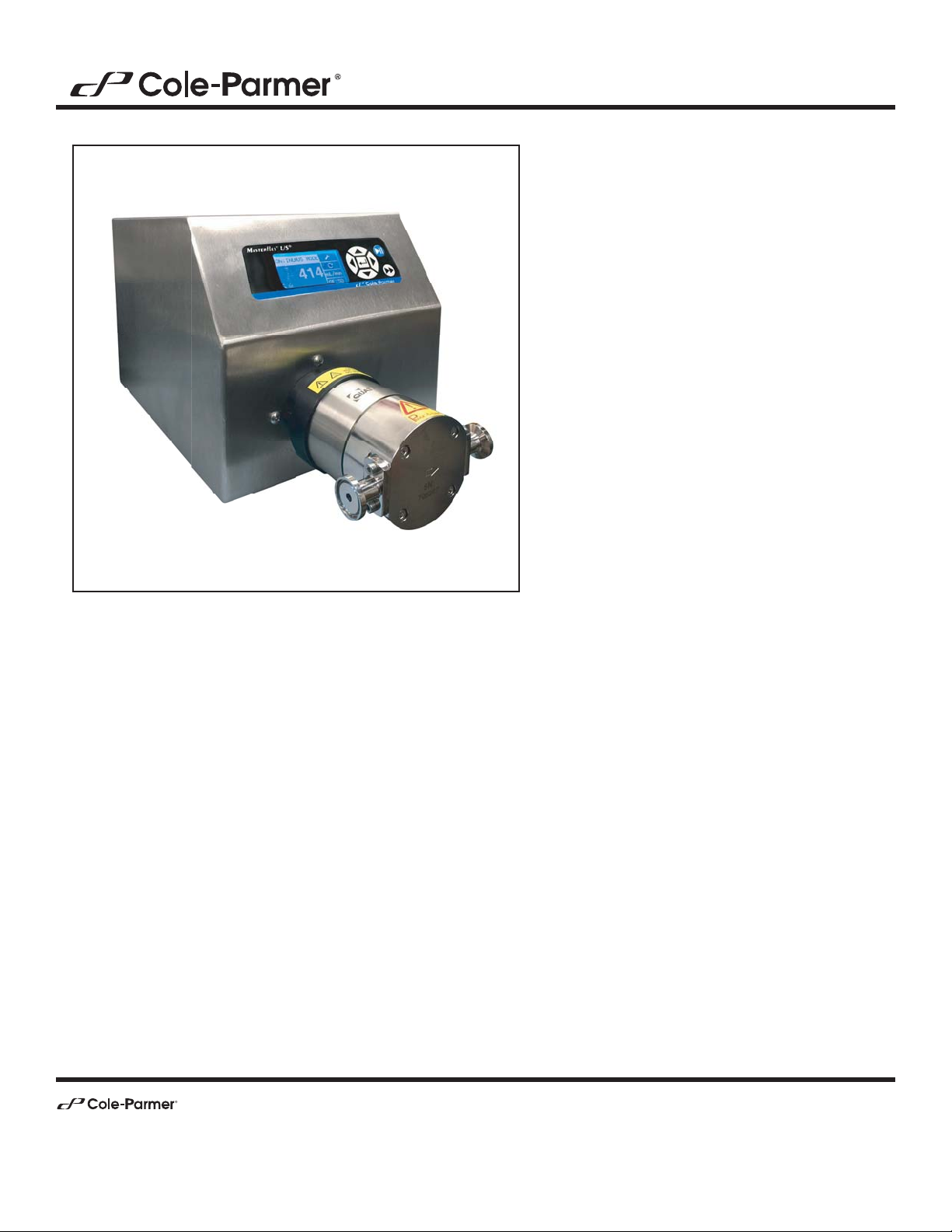
Welcome to the Cole-Parmer Digital Pump Drive. drive has many
of the same functions as the standard MASTERFLEX L/S® Digital
Drive for peristaltic pumps. With Pump Heads the system
rates from 5 to
14,230 mL/min.
Digital Pump Drive Operating Manual 1-1Cole-Parmer
Page 12

Section 1
Introduction
General Description
Cole-Parmer Digital Drive provides a motor speed repeatability of
0.1 percent to maximize productivity in precision liquid dosing, batch
dispensing and
applications. A turndown ratio up to 600-to-1,
self-priming capabilities allow for smooth, seamless operation and an
extremely broad
range.
In addition to high accuracy, precision, repeatability and resolution of
speed (or rate), the Cole-Parmer Drive features a multi-language,
intuitive, man/machine interface with a four-line graphical LCD display
providing direct readout of pump speed (rpm),
rate (user-selected
units), number of dispenses, and menu options.
easy-to-use keypad eliminates setpoint overshoot and provides easy
navigation through menu options that include a number of on-screen
programming features.
Cole-Parmer Drive with its high turndown, superior accuracy, and
intuitive interface make it ideally suited where precise and repeatable
control is required. pump accommodates a variety of product
volumes and batch dispensing
1-2 Digital Pump Drive Operating Manual Cole-Parmer
Page 13

Section 2 Installation and Setup
Before Starting Drive
t e ambient air temperature should not exceed 104° F (40° C) and
adequate air ow should be provided for.
CAUTION: Do not block the rear panel of the Pump Drive. The
power switch must always be easy to access. The power cord
must always be easy to disconnect.
WARNING: Do not operate without pump head mounted. Follow
all instructions for proper operation of pump head
t To maintain the best accuracy of ow rates, re-calibrate Pump Head
regularly. See Calibration Section of this manual.
For Pump Head information, see Pump Head information (see page 6-1)
t
within this CD.
t When cleaning or performing maintenance, please remove power from
the drive.
CAUTION: The power cord set supplied with your Pump Drive
meets the requirements of the country where you purchased the
Pump Drive. If you use the Pump Drive in another country, you
must use a power cord set that meets the requirements of that
country.
DANGER: High voltages exist and are accessible. Use extreme
caution when servicing internal components.
Digital Pump Drive Operating Manual 2-1Cole-Parmer
Page 14

Section 2
Installation and Setup
Mounting the
Pump Head
t See Pump Head information within this CD.
CAUTION: When using hazardous chemical and biological
agents, take all suitable protective measures, such as wearing
protective glasses and gloves resistant to the substances used.
Follow local and/or national regulations for safe operation and
maintenance of the system.
2-2 Digital Pump Drive Operating Manual Cole-Parmer
Page 15
Section 3 Operation
Turning On the Drive
WARNING: Do not operate the Pump Drive in a manner not specified in the documentation. Misuse of the Pump Drive may result
in a hazard and may compromise the safety protection built into
the Pump Drive. If the Pump Drive is damaged, turn it off and not
use it until service-trained personnel can check its safety.
1. Plug the power cord into the IEC Connector, located on the rear of
the drive. Plug the opposite end of the power cord into an electrical
outlet.
2. Flip the power switch located on the rear of the drive.
3. Upon turning on the drive for the rst time you will be prompted to
select a language. e selected language will be set as the default but
can be changed at any time by selecting “LANGUAGE” on the main
menu.
4. After selecting your language, the Main Menu will now appear on the
LCD screen. (NOTE: Each start-up after the initial will revert to the
mode of operation screen previously in use.)
5. If the language is accidently changed and the user would like to reset it
to the default language (English), press and hold the UP/DOWN
/ ) keys during power up.
(
6. To restore drive to default settings, press and hold the LEFT/RIGHT
(/)keys during power up.
CAUTION: To avoid electrical shock, the power cord protective
grounding conductor must be connected to ground. Not for
operation in wet locations as defined by EN61010-1.
CAUTION: Power must be turned off before connecting the external remote control cable to prevent damage to the drive.
Digital Pump Drive Operating Manual 3-1Cole-Parmer
Page 16
Section 3
Operation
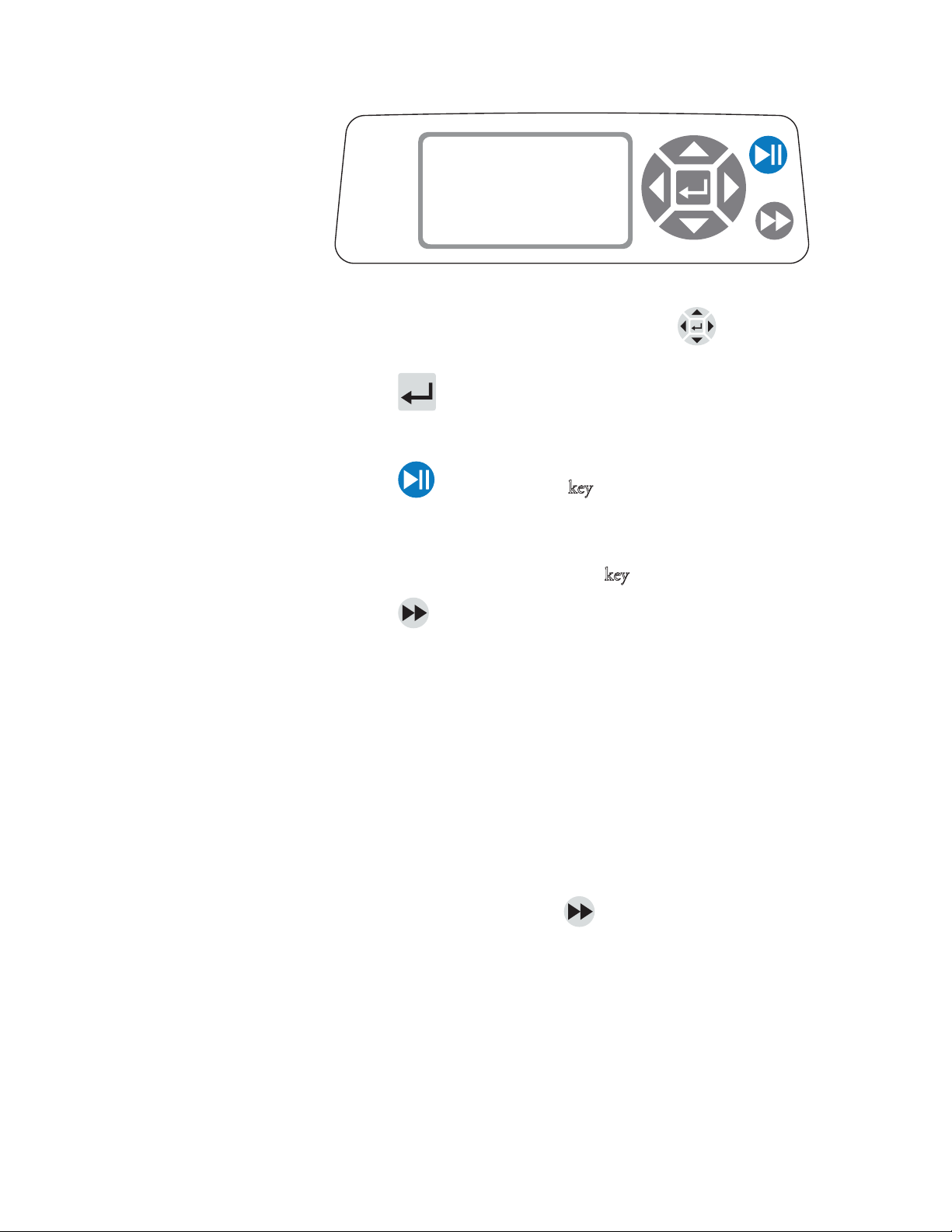
Control Panel
Figure 3-1. Control Panel
t To navigate all menus on the drive use the directional pad
directly to the right of the LCD screen.
t e (ENTER) key located in the middle of the directional pad
is used to enter or select a highlighted eld or option. is key is often
referred to as the ENTER key in this manual.
Priming the Pump
t e (START/STOP) k
panel is used to start and pause the drive. is key is functional only
when in one of the four operating modes: Continuous, Time
Dispense, Copy Dispense, or Volume Dispense. is key is often
referred to as the START/STOP k
t e (PRIME) key located at the bottom right of the control
panel is used to access the prime (fast forward) function. While
pressed, this key operates the drive at the maximum allowed
speed/ow rate and in the direction shown on the display. When
released, the drive returns to its original speed or ow rate.
1. Mount Pump Head to drive.
2. Connect suction and discharge to Pump Head. Follow Pump Head
instructions for priming pump.
3. Turn on pump using switch located on the back of the drive.
4. Press and hold the PRIME key on the drive console to prime the
pump. Priming will stop when key is released.
ey located at the top right of the control
ey in this manual.
5. See Pump Head operating manual for Pump Head operation and
safety requirements.
3-2 Digital Pump Drive Operating Manual Cole-Parmer
Page 17
Section 3
Operation
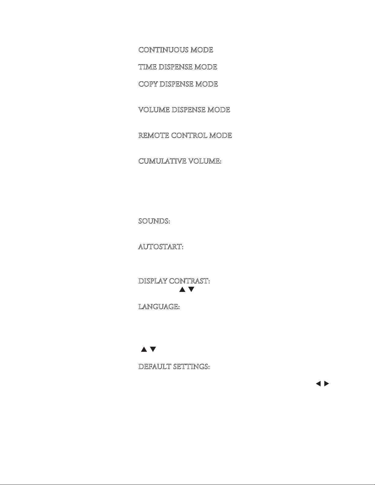
Main Menu
CONTINUOUS MODE refer to Continuous Mode in this manual.
IME DISPENSE MODE refer to Time Dispense Mode in this manual.
T
OPY DISPENSE MODE refer to Copy Dispense Mode section in this
C
manual.
OLUME DISPENSE MODE refer to Volume Dispense Mode section in
V
this manual.
EMOTE CONTROL MODE refer to Remote Control Mode section in
R
this manual.
UMULATIVE VOLUME: e drive stores and displays the cumulative
C
volume in units based on ow rate units (see SETUP MENU in this
section). e Cumulative Volume can also be reset to zero.
NOTE: e Cumulative Volume is dependent on the Pump Head
selected. (See SETUP MENU in this section.)
OUNDS: An audible “beep” can be enabled to indicate a keypad press,
S
the end of a dispense and/or the end of a batch.
UTOSTART: By default the drive will not restart when power is
A
applied. To enable this feature select AUTOSTART and then ON. e
drive will now restart when power is reapplied.
ISPLAY CONTRAST: is display can be adjusted using the
D
UP/DOWN (
ANGUAGE: After selecting this menu, the user will be able to select one
L
/ ) arrows after selecting this menu item.
of seven dierent languages.
NOTE: If the language is accidentally changed and the user would like to
reset it to the default language (English), press and hold the UP/DOWN
/ ) keys when power is reapplied.
(
EFAULT SETTINGS: Selecting this menu item and pressing the
D
ENTER key will restore default settings. To restore drive to default
settings the user may also press and hold the LEFT/RIGHT
(/)keys
when power is reapplied.
Cole-Parmer
Digital Pump Drive Operating Manual 3-3
Page 18

Section 3
Operation
Pump Head
Calibration
1. Mount Pump Head to drive.
2. Connect suction and discharge to Pump Head.
3. Follow Pump Head instructions for priming pump.
4. Container should be a graduated container or a container placed on a
scale may be used for increased accuracy.
If using a scale, an acceptable weight to volume conversion for water is
1 gram = 1 mL.
5. Turn on drive using power switch located on the rear of the drive.
6. Go to the Main Menu or Mode Setup Menu by selecting the SETUP
icon and pressing the ENTER key. Use the UP and DOWN keys
to highlight CAL in the Main or Setup Menu and press the ENTER
key.
7. Set the drive for the desired ow direction, Pump Head, and ow rate.
Note that these settings are retained and transferred to other mode
screens when entering or leaving the CAL screen.
t e ow direction is set using the directional keypad to highlight
the directional arrow. Pressing ENTER will toggle arrow between
CW and CCW.
t e Pump Head is set using the directional keypad to highlight
the Pump Head eld. Press ENTER and use the UP/DOWN keys
to select the Pump Head
and return to CAL screen.
t e estimated ow rate is set using the directional keypad to
highlight the ow rate eld. Press ENTER and use the
LEFT/RIGHT keys to select the digit to be changed. Use the
UP/DOWN keys to adjust the ow rate value. Press ENTER to
SAVE the setting and EXIT eld using arrow keys. e drive will
adjust this ow rate after calibration is complete.
t Note that the calibration volume is xed and cannot be changed.
8. Press and hold the prime key on the drive console to prime the
pump. Priming will stop when key is released.
9. Place a measuring container at the pump outlet. Highlight the START
eld and press the ENTER key. e drive will run based on the
default volume at the estimated ow rate selected.
size. Press ENTER to SAVE the selection
3-4 Digital Pump Drive Operating Manual Cole-Parmer
Page 19

Section 3
Operation
Pump Head
Calibration
(continued)
10. Upon completion of the calibration run period, the CAL VOLUME
will be highlighted. Press the ENTER key and adjust the CAL
VOLUME to the measured quantity. Use the LEFT/RIGHT keys to
select digit to be changed, use the UP/DOWN keys to adjust the
value, and press ENTER to SAVE setting and EXIT the
A lower case “c” should now be displayed when the calibrated Pump
Head size is selected.
units. rate unit mL/min will result in a volume unit of mL;
oz/min will result in a volume unit of oz.
ump Head Calibration Notes
P
t If the drive is stopped during calibration, empty the container and
re-start the procedure.
t Calibration time at maximum allowable
rate) is approximately 30 seconds.
t Minimum and maximum rates will change after a Pump
Head calibration due to a re-calculation of the vol/rev.
volume units will depend on the rate
rate (default max
Table 3-1. Nominal Calibration Volumes
SIZE Max. mL/min Cal. vol in mL
QF150 2900 1150
QF1200 14230 8370
Cole-Parmer
Digital Pump Drive Operating Manual 3-5
Page 20

Section 3
Operation
Setup Menu
All four operation mode screens contain a SETUP icon in the upper
right hand that gives quick access to the SETUP menu. e exact options
that can be accessed through the SETUP menu will depend on the
operating mode currently in use:
electing the SETUP Menu: In any of the four operating modes, use
1. S
the directional pad and enter key to select the SETUP icon from the
mode operation screen.
avigating the SETUP Menu: Use the directional pad and the
2. N
ENTER key to select desired setting.
A breakdown of the setting features common to all modes follows. Other
settings are related to the specic operating mode currently in use and can
be accessed through the mode operation screen as well.
low Unit: Select desired ow unit to be displayed.
F
ump Head: Size and Maximum Flow Rate are displayed. Select desired
P
Pump Head.
low Rate: Set the ow rate in ow unit listed at the top of the screen.
F
(NOTE: To change ow unit, see Flow Unit above.) When the entire rate
eld is highlighted, press ENTER. e digits can be navigated
individually using the UP/DOWN arrows; switch between digits using the
LEFT/RIGHT arrows. After selecting an optimal ow rate, press ENTER
again to validate.
ump Head Calibration: See Pump Head Calibration.
P
S
ounds: Select a beep for keypad, end of dispenses, and batches.
emote Control: See Remote Control.
R
eypad Lockout: Allows for the keypad to be locked and unlocked.
K
umulative Volume: View and reset cumulative volume.
C
ain Menu: Return to the Main Menu.
M
xit: Return to the Mode Operation screen.
E
3-6 Digital Pump Drive Operating Manual Cole-Parmer
Page 21

Section 3
Operation
Continuous Mode
Screen
Display Legend:
Continuous Mode. An explanation of the information on the screen follows.
Figure 3-2. Continuous Mode Screen
ode Display: Current operating mode in which the drive will operate.
A. M
Pressing ENTER key when highlighted will cycle through the dierent
operation modes.
etup :Pressing the ENTER key on this icon goes to the Setup
B. S
screen. e Setup screen contains most functions that can be accessed
from the Continuous Mode operation screen, including: ow units,
Pump Head size, ow rate, pump direction, remote control, and keypad
lockout. e Setup screen also provides access to Pump Head calibration,
sounds, cumulative volume and the Main Menu.
Below is a screenshot of the screen display for the drive in
BA
E
F
G
CONTINUOUS MODE
100.00
or
mL/min
QF150
C
D
low Units: Pressing the ENTER key on this icon goes to the Flow Unit
C. F
selection screen. NOTE: % and rpm are available in Continuous Mode only.
When switching to Copy Dispense or Volume Dispense Modes % and rpm
units will change to mL/min with values dependent on Pump Head size
selected.
ump Head Size: Pressing the ENTER key on this icon goes to the
D. P
Pump Head size selection screen.
urrent Flow Rate: e center digits show the ow rate of the drive in the
E. C
unit of measure selected and shown to the right (see position D, Figure 3-2).
ocal/Remote or :Pressing the ENTER key on this icon goes to
F. L
the Remote Control setup screen. is icon indicates whether your
drive is in local or remote control mode. If the solid rectangle appears
in the center of the gure the drive is set to be operated locally. If the
solid rectangle does not appear in the center of the gure the drive is
set to be operated by remote control.
ey Pad Lock :Pressing the ENTER key on this icon goes to the
G. K
Keypad Lockout screen. Locking the keypad will prevent someone from
changing the settings on the drive. When locked this icon changes to .
Digital Pump Drive Operating Manual 3-7Cole-Parmer
Page 22

Section 3
Operation
Continuous Mode
Operation
CONTINUOUS MODE
100.00
Figure 3-3. Continuous Mode Operation
etting Started: From the Main Menu, use the ENTER key to
1. G
select Continuous Mode to enter the Continuous Mode Operation
screen.
alibrating Pump Head: For more information, see “Pump Head
2. C
Calibration.”
reparing External Supplies: Insert suction end into supply uid. Next,
3. P
insert discharge end into desired container.
tarting the Drive: From this operation screen, simply pressing the
4. S
START/STOP key will start the drive at the speed/ow rate and
direction shown. In Continuous Mode the drive will operate at the
displayed speed/ow rate and direction continuously.
mL/min
QF150
topping the Drive: To pause or stop the drive, press the
5. S
START/STOP key in the top right hand corner of the console.
hanging Speed/Flow Rate: To change the speed/ow rate of the drive,
6. C
use the directional pad to highlight the numeric eld in the center of the
display and press the ENTER key. is puts you in a position to change
the speed/ow rate of the drive at the farthest digit to the right (tenths,
hundredths, thousandths, etc depending on ow unit). Pressing the UP
arrow on the directional pad will increase the speed/ow rate by one
value and pressing the DOWN arrow will decrease the speed/ow rate by
one value. Pressing the ENTER key again will show all the possible digits
that can be manipulated for the specic ow unit currently in use; use the
LEFT/RIGHT arrows on the directional pad to move between digits and
the UP/DOWN arrows to increase or decrease the value, respectively.
Once desired speed/ow rate is selected, press ENTER key a nal time
to set the drive to operate at that speed/ow rate.
hanging Flow Unit: To change the ow unit of the drive pause the
7. C
drive using the START/STOP key. Next, use the directional pad to
select the Flow Units icon and press the ENTER key. Use the
UP/DOWN arrow on the directional pad to select the desired ow
unit and press the ENTER key to choose that unit. e drive will now
operate in that ow unit. Press the START/STOP key to resume
operating the drive.
3-8 Digital Pump Drive Operating Manual Cole-Parmer
Page 23

Section 3
Operation
Time Dispense Mode
Screen
Display Legend: Below is a screenshot of the screen display for the drive in
Time Dispense Mode. An explanation of the information on the screen follows.
BA
TIME DISP. MODE
H
C
F
G
00:00:00
1000/2000
or
ON
OFF
E
D
Figure 3-4. Time Dispense Mode Screen
ode Display: Current operating mode.
A. M
etup : e Setup screen can be used to select ow units, Pump
B. S
Head size, ow rate, Pump Head calibration, sounds, cumulative
volume, and Main Menu. e Setup screen contains some functions
that can be accessed from the Time Dispense Mode operation screen,
including: pump direction, on/o time, batch count, remote control,
and keypad lockout.
ump ON Time: When this eld is highlighted the drive is ON.
C. P
NOTE: e drive will not show 00:00 when switching from ON to
OFF Time.
ump OFF Time: When this eld is highlighted the drive is OFF.
D. P
atch Count: Displays the number of cycles dispensed in the batch.
E. B
ocal/Remote or : Pressing the ENTER key on this icon goes to
F. L
the Remote Control setup screen. is icon indicates whether your
drive is in Local or Remote Control mode. If the solid rectangle
appears in the center of the gure the drive is set to be operated
locally. If the solid rectangle does not appear in the center of the gure
the drive is set to be operated by remote control.
ey Pad Lock : Pressing the ENTER key on this icon goes to the
G. K
Keypad Lockout screen. Locking the keypad will prevent someone
from changing the settings on the drive. When locked this icon
changes to .
ime Display: e center digits show the remaining time of the drive
H. T
in the ON or OFF Time highlighted on the right of the display
(position D or E, Figure 3-4).
Digital Pump Drive Operating Manual 3-9Cole-Parmer
Page 24

Section 3
Operation
Time Dispense
Mode Operation
TIME DISP. MODE
00:00:00
1000/2000
Figure 3-5. Time Dispense Mode Operation
etting Started: From the Main Menu, use the enter key to select Time
1. G
Dispense Mode to enter the Time Dispense Mode Operation screen.
alibrating Pump Head: For more information, see “Pump Head
2. C
Calibration.”
hoosing Settings: Select desired ow unit, Pump Head size, ow rate,
3. C
pump direction, etc. For more information see “SETUP Menu.”
reparing Pump Head: Insert suction end into supply uid. Next,
4. P
insert discharge end into desired container.
electing Flow Rate: Use the directional pad and ENTER key to select
5. S
the Setup icon. Use the UP/DOWN arrows on the directional pad to
select Flow Rate. In the Flow Rate selection screen, press the ENTER
key and then use the UP/DOWN arrows on the directional pad to
select a desired ow rate. For faster entry, use the LEFT/RIGHT
arrows on the directional pad to move between digits and the
UP/DOWN arrows to increase or decrease the value, respectively.
Press ENTER one more time to validate the selected ow rate. Use the
directional pad to select EXIT to return to the Time Dispense Mode
Setup Screen.
ON
OFF
etting ON Time: To set the ON Time, use the directional pad and
6. S
ENTER key to select the ON eld (see position D, Figure 3-4). Doing
so will highlight the timer in the center of the screen (see position I,
Figure 3-4). Pressing ENTER again, allows the timer to be set using
the UP/DOWN arrows. Switch between digits using the
LEFT/RIGHT arrows. Having selected an optimal ON Time, press
ENTER again to validate. e drive will now run for the time
appearing in the center of the screen.
3-10 Digital Pump Drive Operating Manual Cole-Parmer
Page 25

Section 3
Operation
Time Dispense Mode
Operation (continued)
7. Setting OFF Time: To set the OFF Time, use the directional pad and
ENTER key to select the OFF eld (see position E, Figure 3-4). Doing
so will highlight the timer in the center of the screen (see position I,
Figure 3-4). Pressing ENTER again, allows the timer to be set using
the UP/DOWN arrows. Switch between digits using the
LEFT/RIGHT arrows. Having selected an optimal OFF Time, press
ENTER again to validate. e drive will stop running for the time
appearing in the center of the screen. NOTE: If the OFF Time is set to
00:00:00, the drive requires a START/STOP input from the keypad
or the remote I/O Connector to start the next dispense.
electing Batch Size: Before running the drive at the selected ON/
8. S
OFF Times, select a batch size for the operation. To do so, use the
directional pad and the ENTER key to select the BATCH icon (see
position F, Figure 3-4). In the Batch Count screen, press the ENTER
key and then use the UP/DOWN arrows on the directional pad to
select a batch size. Switch between digits using the LEFT/RIGHT
arrows. Press ENTER one more time to validate the selected batch size.
When set to zero (0) the drive will run for an innite number of cycles
and the
to return to the Time Dispense Operation Screen.
symbol is displayed. Use the directional pad to select EXIT
tarting the Drive: e drive is now set to operate, press the
9. S
START/STOP key in the upper right hand corner to start the drive.
e drive can be paused at any time throughout the batch to adjust
ow direction, Pump Head size, ow units, ow rate, etc.
esetting Batch: To reset a batch, use the directional pad and the
10. R
ENTER key to select the BATCH icon (see position F, Figure 3-4). In
the Batch Count screen, use directional pad to select RESET and press
the ENTER key to reset the batch count, select EXIT to return to the
main Time Dispense Mode operation screen.
Digital Pump Drive Operating Manual 3-11Cole-Parmer
Page 26

Section 3
Operation
Copy Dispense Mode
Screen
Display Legend: Below is a screenshot of the screen display for the drive in
Copy Dispense Mode. An explanation of the information on the screen
follows.
BA
I
F
G
COPY DISP. MODE
100.00
53 %
1000/2000
or
C
COPY
OFF
H
E
D
Figure 3-6. Copy Dispense Mode Screen
ode Display: Current operating mode.
A. M
etup :e Setup screen can be used to select ow units, Pump
B. S
Head size, ow rate, Pump Head calibration, sounds, cumulative
volume, and Main Menu. e Setup screen contains some functions
that can be accessed from the Time Dispense Mode operation screen,
including: pump direction, on/o time, batch count, remote control,
and keypad lockout.
opy Amount Screen: See Copy Setting Screen, Figure 3-8.
C. C
ump OFF Time: Highlighted when the drive is OFF.
D. P
atch Count: Displays the number of cycles dispensed in the batch.
E. B
ocal/Remote or :Pressing the ENTER key on this icon goes to
F. L
the Remote Control setup screen. is icon indicates whether your
drive is in local or remote control mode. If the solid rectangle appears
in the center of the gure the drive is set to be operated locally. If the
solid rectangle does not appear in the center of the gure the drive is
set to be operated by remote control.
eypad Lock : Pressing the ENTER key on this icon goes to the
G. K
Keypad Lockout screen. Locking the keypad will prevent someone
from changing the settings on the drive. When locked this icon
changes to .
ercentage Completed: is icon displays the portion of uid
H. P
dispensed as a percentage.
opy Volume: Displays the Copy Volume while dispensing or the
I. C
OFF Time.
3-12 Digital Pump Drive Operating Manual Cole-Parmer
Page 27

Section 3
Section 3
Operation
Operation
Copy Dispense Mode
Operation
COPY DISP. MODE
100.00
53 %
1000/2000
Figure 3-7. Copy Dispense Mode Operation
etting Started: From the Main Menu, use the ENTER key to select
1. G
Copy Dispense Mode to enter the Copy Dispense Mode operation
screen.
alibrating Pump Head: For more information, see “Pump Head
2. C
Calibration.”
hoosing Settings: Select desired ow unit, Pump Head size, ow
3. C
rate, pump direction, etc. For more information see “Using the
SETUP Menu.”
reparing Pump Head: Insert suction end into supply uid. Next,
4. P
insert discharge end into desired container.
COPY
OFF
etting Copy Amount: See Copy Setting Operation.
5. S
etting OFF Time: Use the directional pad and ENTER key to select
6. S
OFF on the display to enter the Pump OFF Time. Use the directional
pad and ENTER key to set the Pump OFF Time. e timer in the
center of the screen will be highlighted, and using the UP/DOWN
arrows will increase/decrease the farthest right digit of the time
interval. Switch between digits using the LEFT/RIGHT arrows. After
selecting an optimal OFF Time, press ENTER again to validate. e
drive will now rest for the time appearing in the center of the screen.
NOTE: If the OFF Time is set to 00:00:00, the drive requires a
START/STOP input from the keypad or the remote I/O Connector
to start the next dispense.
etting Batch Size: Use the directional pad and ENTER key to select
7. S
the Batch Count icon from the operation screen (see position F,
Figure 3-6). From Batch Count screen use the UP/DOWN arrows to
select batch size. Press ENTER to validate batch size. When set to zero
(0) the drive will run for an innite number of cycles and the
symbol is displayed. Select EXIT to return to the Copy Dispense
Mode screen.
t Batch count may be reset from BATCH COUNT screen by
selecting RESET.
Digital Pump Drive Operating Manual 3-13Cole-Parmer
Page 28

Section 3
Operation
Copy Dispense Mode
Operation (continued)
8. Operating Drive: Press the START/STOP key to operate the drive at
the settings selected and displayed on the screen. Press again to pause
or stop the drive. Drive will automatically stop once batch is complete.
eset Batch Count: Use the directional pad and the ENTER key to
9. R
select the BATCH COUNT icon (see position F, Figure 3-6). In the
BATCH COUNT screen, select RESET and press the ENTER key to
reset the batch count. Select EXIT to return to the Copy Mode
Operation screen.
aximum Dispense Time: e specication for the maximum
10. M
dispense in Copy Mode is over 80+ hours at 3000 rpm. Actual
maximum volume is dependant on Pump Head size and ow units
selected.
3-14 Digital Pump Drive Operating Manual Cole-Parmer
Page 29

Section 3
Operation
COPY Setting Screen
Display Legend: Below is a screenshot of the screen display for the drive in
Copy Setting Mode. An explanation of the information on the screen follows.
BA
G
F
10000
EXIT CLEAR
COPY START
C
mL
D
STOP
E
Figure 3-8. COPY Setting Screen
ode Display: Current operating mode.
A. M
TART: is icon will start drive allowing for copy volume to be set.
B. S
C. V
olume Unit: is is dependent on the ow rate selected.
TOP: is stops the Copy and sets the volume to be dispensed. It is
D. S
displayed in position H.
LEAR: Selecting this will clear the number displayed on the screen
E. C
and will allow for a new copy volume to be selected.
XIT: Return to Copy Dispense Mode.
F. E
olume: is is the amount that was dispensed during the copy.
G. V
Digital Pump Drive Operating Manual 3-15Cole-Parmer
Page 30

Section 3
Operation
COPY Setting
Operation
COPY START
10000
EXIT CLE A R
Figure 3-9. COPY Setting Operation
etting Started: From the COPY DISPENSE MODE Screen select
1. G
COPY and ENTER.
lear Volume: Using the directional Keypad select CLEAR and ENTER.
2. C
stablish Copy Volume: 3 methods are available to the user.
3. E
a. Place the desired container at the discharge end. Press the
START/STOP key to initiate the dispensing of uid. When you have
reached the desired volume press the START/STOP key again. Select
EXIT and press ENTER. e drive will store the value of the copy in
memory and use that value in the COPY DISPENSE MODE.
mL
STOP
b. Place the desired container at the discharge end. Select the START eld
on the screen and press the ENTER key to initiate the dispensing of
uid. e drive will now highlight the STOP eld on the screen. When
you have reached the desired volume press the ENTER key to stop.
Select EXIT and press ENTER. e drive will store the value of the
copy in memory and use that value in the COPY DISPENSE MODE.
c. Place the desired container at the discharge end. Close the contacts
on the START/STOP input to initiate the dispensing of uid.
When you have reached the desired volume, close and release the
contacts on the START/STOP input. Select EXIT and press
ENTER. e drive will store the value of the copy in memory and
use that value in the COPY DISPENSE MODE.
NOTE: e value displayed
and the COPY DISPENSE Mode screen depend on the ow units selected.
RPM, and % are invalid. If these units have been selected the drive will
display a volume in mL, in the COPY DISPENSE MODE, that is
dependent on the Pump Head size selected.
See PUMP HEAD CALIBRATION to improve the accuracy of this
conversion.
as the volume in the COPY SETTING screen
3-16 Digital Pump Drive Operating Manual Cole-Parmer
Page 31

Section 3
Operation
Volume Dispense
Mode Screen
Display Legend: Below is a screenshot of the screen display for the drive
in Volume Dispense Mode. An explanation of the information on the
screen follows.
BA
H
F
G
VOL DISP. MODE
100.00
1000/2000
or
C
mL
OFF
E
D
Figure 3-10. Volume Dispense Mode Screen
ode Display: Current operating mode.
A. M
etup : e Setup screen can be used to select ow units, Pump
B. S
Head size, ow rate, Pump Head calibration, sounds, cumulative
volume, and Main Menu. e Setup screen contains some functions
that can be accessed from the Time Dispense Mode operation screen,
including: pump direction, on/o time, batch count, remote control,
and keypad lockout.
low Units: Select desired ow unit.
C. F
ump OFF Time: Highlighted when the drive is OFF.
D. P
atch Count: Displays the number of cycles dispensed in the batch.
E. B
ocal/Remote or :Pressing the ENTER key on this icon goes to
F. L
the Remote Control setup screen. is icon tells you whether your
drive is in local or remote control mode. If the solid rectangle appears
in the center of the gure the drive is set to be operated locally. If the
solid rectangle does not appear in the center of the gure the drive is
set to be operated by remote control.
eypad Lock :Pressing the ENTER key on this icon goes to the
G. K
Keypad Lockout screen. Locking the keypad will prevent someone from
changing the settings on the drive. When locked this icon changes to .
olume: Displays the Volume while dispensing or the OFF Time.
H. V
Digital Pump Drive Operating Manual 3-17Cole-Parmer
Page 32

Section 3
Operation
Volume Dispense
Mode Operation
VOL DISP. MODE
100.00
1000/2000
Figure 3-11. Volume Dispense Mode Operation
Getting Started: From the Main Menu, use the ENTER key to select Volume
1.
Dispense Mode to enter the Volume Dispense Mode operation screen.
2. Calibrating Pump Head. For more information, see “Pump Head
Calibration.”
hoosing Settings: Select desired ow unit, Pump Head size, ow rate,
3. C
pump direction, etc. For more information see “SETUP Menu.”
reparing Tubing: Insert suction end into supply uid. Next, insert
4. P
discharge end into desired container.
etting Desired Volume: Using the directional pad highlight the numeric
5. S
eld in the center of the display and press the ENTER key. is puts you
in a position to change the uid volume of the drive at the farthest digit to
the right (tenths, hundredths, thousandths, etc., depending on your volume
unit). Pressing the UP arrow on the directional pad will increase the
volume by one value and pressing the DOWN arrow will decrease the
volume by one value. Pressing the ENTER key again will show all the
possible digits that can be manipulated for the specic volume unit
currently in use; use the LEFT/RIGHT arrows on the directional pad to
move between digits and the UP/DOWN arrows to increase or decrease
the value, respectively. Once desired volume is selected, press ENTER a
nal time to set the drive to operate at that volume. Press the
START/STOP key to resume operating the drive.
mL
OFF
etting Pump OFF Time: Use the directional pad and ENTER key to
6. S
select OFF on the display (see position E, Figure 3-10) to enter the OFF
TIME. Use the directional pad and ENTER key to set the pump rest time.
e timer in the center of the screen will be highlighted, and using the
UP/DOWN arrows will increase/decrease the farthest right digit of the
time interval. If ENTER is pressed a second time while the timer is
highlighted, the digits can be navigated individually using the UP/DOWN
arrows; switch between digits using the LEFT/RIGHT arrows. After
selecting an optimal OFF time, press ENTER again to validate. e drive
will now rest for the time appearing in the center of the screen. NOTE: If
the OFF Time is set to 00:00:00, the drive requires a START/STOP input
from the keypad or the remote I/O Connector to start the next dispense.
3-18 Digital Pump Drive Operating Manual Cole-Parmer
Page 33

Section 3
Operation
Volume Dispense
Mode Operation
(continued)
7. Setting Batch Size: Use the directional pad and ENTER key to select
the Batch Count icon from the operation screen (see position F,
Figure 3-10). From Batch Count screen use the UP/DOWN arrows to
select batch size. Press ENTER to validate batch size. When set to zero
(0) the drive will run for an innite number of cycles and the ∞
symbol is displayed. Select EXIT to return to drive operation screen.
t Batch count may be reset from the Batch Count screen by selecting
RESET.
perating the Drive: Press the START/STOP key to operate the drive
8. O
continuously at the settings selected and displayed on the screen. Press
again to pause or stop the drive. Drive will automatically stop once
batch is complete.
eset Batch Count: Use the directional pad and the ENTER key to
9. R
select the BATCH COUNT icon (see position F, Figure 3-10). In the
BATCH COUNT screen, select RESET and press the ENTER key to
reset the batch count. Select EXIT to return to the COPY MODE
OPERATION screen.
aximum Dispense Time: e specication for the maximum
10. M
dispense volume in Volume Mode is over 80+ hours at 3000 rpm.
Actual maximum volume is dependant on Pump Head size and ow
units selected.
Digital Pump Drive Operating Manual 3-19Cole-Parmer
Page 34

Section 3
Operation
Remote Control Menu
REMOTE CONTROL
LOCAL
CURRENT INPUT
CURRENT OUTPUT
VOLTAGE INPUT
VOLTAGE OUTPUT
START/STOP
EXIT
Figure 3-12. Remote Control Menu Screen
AVIGATION: From the Main Menu or SETUP Menu select
N
REMOTE CONTROL and ENTER.
OCAL: When this is selected the drive is controlled by the front panel
L
keypad, Start/Stop Input, Directional Input or Prime Input.
URRENT INPUT: When this is selected, the drive is in remote control.
C
is allows the user to input a current signal to control the ow. e user has
an option to adjust the minimum, maximum and middle set points for
current and ow. By default the minimum (MIN) current is set to 4.2 mA
and the ow is set to 0. e maximum (MAX) is set to 20 mA and the ow is
set to maximum. e middle (MID) is auto calculated for a current and ow
that is centered between the MIN and the MAX. e MID can be adjusted if
other proles are needed. e scaling can be inverted if necessary. To conrm
CURRENT INPUT MODE is selected, select EXIT after returning to the
Remote Control Menu, then select CONTINUOUS PUMP MODE. To
deselect Remote Current Input Mode select LOCAL and ENTER.
NOTE: When Current Input is selected the drive will not start until the
REMOTE CONTROL MODE is exited and CONTINUOUS PUMP
MODE is selected.
URRENT OUTPUT: is allows the user to adjust the current output for a
C
given ow. e user has an option to adjust the minimum, maximum and
middle setpoints for current and ow. By default the minimum (MIN) ow is set
to 0.00 and the current is set to 4.0 mA. e maximum (MAX) is set to
maximum ow and the current is set to 20.0 mA. e middle (MID) is auto
calculated for a current and ow that is centered between the MIN and the
MAX. e MID can be adjusted if other proles are needed. is allows for a
three-point calibration of the current output. e ow is linear between these
points. e scaling can be inverted if necessary. NOTE: Selecting Current Output
will not put user into REMOTE CONTROL MODE. Only selecting
VOLTAGE INPUT or CURRENT INPUT will put the user into Remote
Control Mode, as indicated by the empty house icon (see position G, Figure 3-2).
NOTE: e Current Output indicates the Running Command Speed. Use the
Motor Running contacts (normally open/closed) to indicate if pump is running.
3-20 Digital Pump Drive Operating Manual Cole-Parmer
Page 35

Section 3
Operation
Remote Control Menu
(continued)
VOLTAGE INPUT: When this is selected, the drive is in remote control.
is allows the user to input a voltage signal to control the ow. e user
has an option to adjust the minimum, maximum and middle setpoints
for voltage and ow. By default the minimum (MIN) voltage is set to
00.1 V DC and the ow is set to 00.0. e maximum (MAX) is set to
10.0 V DC and the ow is set to maximum. e middle (MID) is auto-
calculated for a voltage and ow that is centered between the MIN and
the MAX. e MID can be adjusted if other proles are needed. e
scaling can be inverted, if necessary. To conrm VOLTAGE INPUT
MODE is selected, select EXIT after returning to the Remote Control Menu,
then select CONTINUOUS PUMP MODE. To deselect Remote Voltage
Input Mode select Local and ENTER.
NOTE: When Voltage Input is selected the drive will not start until the
REMOTE CONTROL MODE is exited and CONTINUOUS PUMP
MODE is selected.
OLTAGE OUTPUT: is allows the user to adjust the voltage output for a
V
given ow. e user has an option to adjust the minimum, maximum and
middle set points for voltage and ow. By default the minimum (MIN) ow
is set to 00.00 and the voltage is set to 00.0V DC. e maximum (MAX) is
set to maximum ow and the voltage is set to 10.0V DC. e middle (MID)
is auto calculated for a voltage and ow that is centered between the MIN and
the MAX. e MID can be adjusted if other proles are needed. is allows
for a three point calibration of the voltage output. e ow is linear between
these points. e scaling can be inverted if necessary. NOTE: Selecting Voltage
Output will not put the user into Remote Control Mode. Only selecting
Voltage Input or Current Input will put the user into Remote Control Mode,
as indicated by the empty house icon (see position G, Figure 3-2). NOTE: e
Voltage Output indicates the Running Command Speed. Use the Motor
Running outputs to indicate if pump is running.
TART/STOP: e START/STOP input can be congured to be OFF
S
(factory default), or ON for the drive to run.
With the OFF selected (factory default), use of the START/STOP input is
optional. When the START/STOP input is open, the drive can still be started
using the START/STOP key, PRIME key, or PRIME input. In remote modes
the drive will also run if there is sucient current or voltage at the input.
Closing the START/STOP input will cause the drive to run until the
START/STOP input opens or the START/STOP key is pressed. In Time
dispense, Copy dispense, and Volume dispense mode, only a momentary
START/STOP closure is needed to start the drive. If the drive is already
running in one of the dispense modes, a momentary START/STOP
closure will stop the drive. In SET COPY MODE, the START/STOP
input functions the same as in CONTINUOUS MODE; closing it will
cause the drive to run until it opens.
Digital Pump Drive Operating Manual 3-21Cole-Parmer
Page 36

Section 3
Operation
Remote Control Menu
(continued)
e function of the START/STOP input is considerably simplied when
the ON is selected. e drive will not run under any condition unless the
START/STOP input is closed.
Table 3-2. Continuous Mode Operation
SETUP OPTIONS INPUT
AUTO START/STOP Drive State When Drive Response When Drive Running
ATS
When Powered OFF
Drive Response when
Powered ON
(sufficient level present)
OFF OFF OPEN Running Not running Not running
OFF OFF OPEN Not running Not running Not running
OFF OFF CLOSED Forced run due Not running Not running
to S/S CLOSED
OFF ON OPEN Forced not running Not running Not running
due to S/S OPEN
OFF ON CLOSED Forced run due Not running Not running
to S/S CLOSED
ON OFF OPEN Running Running Running
ON OFF OPEN Not running Not running Running
ON OFF CLOSED Forced run due Running Running
to S/S CLOSED
ON ON OPEN Forced not running Not running Not running
due to S/S OPEN
ON ON CLOSED Forced run due Running Running
to S/S CLOSED
NOTE: In Continuous Mode when using the START/STOP input the drive is started with a closed contact and
stopped when the contacts are opened.
EDOM V ro AmEDOM LANRETNI POTS/TRATSSGNITTES UNEM
)level tneiciffus(NO derewoPFFO derewoPDERIUQERTR
Table 3-3. Dispense Mode Operation
MENU SETTING SETUP OPTIONS START/STOP Drive State When Drive Response When
INPUT Powered OFF Powered ON
AUTO START START/STOP
REQUIRED
OFF OFF OPEN Running Not running
OFF OFF OPEN Not running Not running
OFF OFF CLOSED* Forced run due Not running
to S/S CLOSED
OFF ON OPEN Forced not running Not running
due to S/S OPEN
OFF ON CLOSED Forced run due Not running
to S/S CLOSED
ON OFF OPEN Running Running
ON OFF OPEN Not running Not running
ON OFF CLOSED* Forced run due Running
to S/S CLOSED
ON ON OPEN Forced not running Not running
due to S/S OPEN
ON ON CLOSED Forced run due Running
to S/S CLOSED
* NOTE: In Dispense Modes and START/STOP MENU SETUP Option OFF the drive will start a dispense
with a momentary contact closure and stop with a momentary contact closure during both the dispense
period and interval period.
3-22 Digital Pump Drive Operating Manual Cole-Parmer
Page 37

Section 3
Operation
DB-25 Pin
Configuration with
Wiring Scheme
Contact Arrangements
L
K
IH B D
13 112 11 10 9 8 7 6 5 4 3 2
25 24 23 22 21 20 19 18 17 16 15 14
J
A. START/STOP
B. C.OUTPUT 0-20mA; 4-20mA
INPUT 0-20mA; 4-20mA
D.
INPUT 0-10V
E.
OUTPUT 0-10V
F.
TACH OUTPUT
G.
PRIME
H.
I.
J.
K.
L.
F
GA
MOTOR RUNNING N.O. CONTACT (1A @ 24 V)
MOTOR RUNNING N.C. CONTACT (1A @ 24 V)
24V (150mA max.)
General Alarm
Local.Remote Indicator
Figure 3-13. DB-25 Pin Configuration with Wiring Scheme
Pin No. Description
DB-25
1 Speed Control Voltage Input (0-10 V)
2 Speed Control Current Input (0-20 mA)
3 Speed Control Input Ground Return
4 Speed Signal Current Output (0-20 mA)
5 Speed Signal Output Ground Reference
6 (Motor Running N.O. Default) 1A @24 V (Open Collector)
7 Motor Running Ground Return
8 (Motor Running N.C. Default) 1A @24 V (Open Collector)
14 Speed Signal Voltage Output (0-10 V)
15 Remote Start/Stop Input
16 Reserved – Not Used
17 Remote Start/Stop, Prime Grnd Ref.
18 Tach Ground Reference
19 Tach Output (Open Collector)
20 Remote Prime Input
19 Reserved – Not Used
10 Reserved – Not Used
11 Reserved – Not Used
12 Reserved – Not Used
21 Reserved – Not Used
22 Reserved – Not Used
23 General Alarm (Open Collector)
24 Local.Remote Indicator (Open Collector)
25 Aux 24V+ (150 mA)
)Am 051( -V42 xuA31
E
C
NOTE: Pins 5, 13, 17, and 18 are at earth ground, all are suitable for use
with START/STOP, PRIME, Tach, LOCAL/REMOTE, General Alarm
Signals and Current and Voltage Outputs.
CAUTION: Power must be turned off before connecting the
external remote control cable to prevent damage to the drive.
NOTE: Open collector outputs in "low impedance" state are at earth
ground and when in "high impedance" state are essentially oating. See
Open Collector page following.
Digital Pump Drive Operating Manual 3-23Cole-Parmer
Page 38

Section 3
Operation
31-Pin
Configuration with
Wiring Scheme
Contact Arrangements
14
18
31- #20
8
3
1
2
7
13
19
25
30
31
29
24
Figure 3-14. 31-Pin Configuration with Wiring Scheme
Pin No. Description
1 Speed Control Voltage Input (0-10 V)
2 Speed Signal Voltage Output (0-10 V)
3 Speed Control Current Input (0-20 mA)
4 Remote Start/Stop Input
5 Speed Control Input Ground Return
6 Reserved – Not Used
7 Speed Signal Current Output (0-20 mA)
8 Remote Start/Stop, Prime Grnd Ref.
9 Speed Signal Output Ground Reference
10 Tach Ground Reference
11 (Motor Running N.O. Default) 1A @24 V (Open Collector)
12 Tach Output (open collector)
13 Motor Running Ground Return
14 Remote Prime Input
15 (Motor Running N.C. Default) 1A @24 V (Open Collector)
16 Reserved – Not Used
17 Reserved – Not Used
18 Reserved – Not Used
19 Reserved – Not Used
20 General Alarm (Open Collector)
21 Reserved – Not Used
22 Local.Remote Indicator (Open Collector)
23 Reserved – Not Used
24 Aux 24V+ (150 mA)
25 Aux 24V- (150 mA)
26 Reserved – Not Used
27 Reserved – Not Used
28 Reserved – Not Used
29 Reserved – Not Used
30 Reserved – Not Used
31 Reserved – Not Used
NOTE: Pins 8, 9, 10, and 25 are at earth ground, all are suitable for use
with START/STOP, PRIME, Tach, LOCAL/REMOTE, General Alarm
Signals and Current and Voltage Outputs.
CAUTION: Power must be turned off before connecting the
external remote control cable to prevent damage to the drive.
NOTE: Open collector outputs in "low impedance" state are at earth
ground and when in "high impedance" state are essentially oating. See
Open Collector page following.
3-24 remraP-eloC
launaM gnitarepO evirD pmuP latigiD
Page 39

Section 3
Operation
Remote Control Inputs
and Outputs
INPUTS
emote Start/Stop, Remote Prime, & Aux. In:
R
e remote control inputs work with current sinking outputs (opencollector NPN transistor outputs without passive pull-up resistors) or
contact closures to DC common (earth ground). A continuous active low
to the Remote Start/Stop input causes the drive to run. A continuous
active low to the Remote Prime input causes the drive to run at full
rated speed.
Table 3-4. Remote Control Inputs and Outputs
CURRENT CLOSED INPUT 1 mA TYP
VOLTAGE OPEN INPUT 3.2 V TYP
THRESHOLD CURRENT TO ACTIVATE 0.5 mA TYP
Remote Analog Input:
4-20 mA Input: 250 ohms typical input impedance ref. to signal
ground. 4 mA, Stop; 20 mA, Full Speed (Default
Settings) 10 Bit Resolution
Overload Capability: 10 V or 40 mA max.
0-10 V Input: 10 K ohms typical input impedance ref. to signal
ground. 0 V, Stop; 10 V, Full Speed (Default
Settings) 10 Bit Resolution
OUTPUTS
4-20 mA Output: 0 to 600 ohms max. load referenced to earth ground.
4 mA, Stop; 20 mA, Full Speed (Default
Settings) 10 Bit Resolution
0-10 V Output: 1.0 K ohms min. load referenced to earth
ground. 0 V, Stop; 10 V, Full Speed (Default
Settings) 10 Bit Resolution
Tach Output: Open Collector, 1.0A @ 28V DC
Frequency range: 60 to 6000Hz 50% Duty Cycle. (10 Hz = 6
pump rpm)
Logic Outputs: Open Collector, 1.0 A @ 28V DC
Motor Running Outputs: Normally Open and Normally Closed when drive is
running.
General Alarm Output: Open (High Impedance) when an alarm is displayed.
Local/Remote Indicator: Open (High Impedance) when in remote
control mode (Voltage Input or Current Input).
Digital Pump Drive Operating Manual 3-25Cole-Parmer
Page 40

Section 3
Operation
Open Collector
Outputs
Some remote outputs on this drive (Tachometer, Local/Remote, and
Alarm) are “open collector” type outputs and cannot be wired in the same
manner as relay outputs. An open collector output is not isolated and
must be congured dierently than a relay output.When the open
collector output is active, the output is eectively switched to earth ground
and if improperly terminated could result in damage to the drive and/or
external equipment.
Recommendation
When connecting to open collector outputs, the output should be
connected to a current limiting resistor and then to a positive supply
source which is less than 28V DC. Typically this would be connected to a
24V PLC input (see Figure 3-14).
NOTE: when using the 24V supply on the interface connector, current
draw must be limited to 150 mA.
NOTE: DO NOT connect 120V supply lines to open collector outputs!
+24V
10k
Output
To PLC
Figure 3-14. Terminating Open Collector Outputs to a PLC
3-26 Digital Pump Drive Operating Manual Cole-Parmer
Page 41

Section 4 Maintenance
Replacement Parts
and Accessories
WARNINGS: The Power switch on the Back Panel is not
the main disconnect. Main disconnect is accomplished by
disconnecting the detachable power supply cord at the
appliance coupler or at the main plug. Ensure the power cord is
easily accessible and removable, in the event of an emergency,
which requires immediate disconnection.
The operator should check the detachable power supply cord
condition. The equipment should not be operated if
supply cord is cracked or broken. Any obvious damage to the
enclosure (from a drop or fall) should be checked by service
personnel for loose or damaged parts inside.
CAUTIONS: Replace the power cord only with one of the same
type and rating. The minimum power ratings are stated on the
rear panel.
The power cord set supplied with your Pump Drive meets the
requirements of the country where you purchased the Pump
Drive. If you use the Pump Drive in another country, you must use
a power cord set that meets the requirements of that country.
the power
Description Part Number
77500-25Fuse-T3.15A, 5 x 20mm
Fuse-T6.3A, 5 x 20 mm 77500-24
Elastomeric Spider
Digital Pump Drive Operating Manual 4-1Cole-Parmer
76000-13
Page 42

Section 4
Maintenance
Fuse Replacement
1. Place the power switch in the position.
2. Disconnect the AC power input line cord from the receptacle.
3. Remove and check the fuse and replace if defective.
A
B
C
D
Style “A”
Style “B”
E
C
B
D
E
BD
C
Figure 4-1. Fuse Replacement
Item Description
A I/O Receptacle DB-25 Pin (Style A and B)
B IEC Power Entry Module / Line Cord
QF150- T3.15A (5 x 20mm) Fuse- Do Not Substitute
C
D Power Switch – All settings are
E I/O Receptacle 31-Pin (Style B)
QF1200- T6.3A (5 x 20mm) Fuse- Do Not Substitute
retained in memory
4-2 Digital Pump Drive Operating Manual remraP-eloC
Page 43

Section 5 Troubleshooting
Troubleshooting Chart
ydemeResuaCmotpmyS
Motor does not rotate, No Power. 1. Check fuse and replace,
.yrassecen fi .thgil ton seod yalpsiD
2. Check that unit is plugged
into a live line.
3. Check connection of
power cord.
4. Check the line cord for
continuity and replace
if defective.
5. Return for servicing.
Motor does not rotate. Defective Remote Control or 1. Place power switch in
Display lights. Setting Error. OFF position.
2. Check that remote cable
connector is fully inserted
into the receptacle.
3. Reapply power.
4. If motor still does not rotate,
select remote control in Main
Menu or Setup Menu and
verify settings.
5. Return to Mode screen and
verify icon shows
Remote Control Mode.
6. See
Remote Control Mode
this manual for further details.
START/STOP Mode “ON” with- 1. See
out an input at I/O Connector. this manual for further details.
Remote Control Mode
2. Select “OFF” in START/STOP
Menu to run without an input
at the I/O Connector cable.
in
in
Digital Pump Drive Operating Manual 5-1Cole-Parmer
Page 44

Section 5
Troubleshooting
Error Definitions
Error #2 Motor Overspeed
Description: The drive has exceeded commanded speed value.
Error Condition(s): The motor has exceeded the commanded speed value
by 20%.
Actions: Drive will stop immediately. Verify load is correct and power
cycle drive. If error persists consult factory.
Error #3: Instantaneous Over-Current
Description: Motor is drawing too much current for a short duration
of time.
Error Condition(s): The motor current is above 4.0 A peak.
Actions: Drive will stop immediately. Verify that Pump Head is not
binding and that the load is not above recommended
maximum load. If error persists consult factory.
Error #4: Bad Flash Checksum
Description: Run-time checksum (checked at power-on) contains a
bad checksum value.
Error Condition(s): Checksum is checked at power-on for an invalid value.
Actions: Power cycle the drive. If error persists consult factory.
Error #7: Bad EEPROM Checksum (Settings)
Description: Bad EEPROM checksum on parameter values and settings, or
its data is out of range.
Error Condition(s): 1) Checksum value in EEPROM does not match
calculated value.
2) Data in EEPROM is out of range.
Actions: Error will be cleared after 10 seconds and parameters will be
reset to default values. If error persists consult factory.
Error #8: Bad EEPROM Checksum (Factory Cal)
Description: Bad EEPROM checksum for Factory Cal
Error Condition(s): 1) Checksum value in EEPROM does not match
calculated value.
2) Data in EEPROM is out of range.
Actions: Error will be cleared after 10 seconds and parameters will be
reset to default values. If error persists consult factory.
5-2 Digital Pump Drive Operating Manual Cole-Parmer
Page 45

Section 5
Troubleshooting
Error Definitions
(continued)
Error #9: EEPROM Write Verification Error
Description: Data written to EEPROM does not match.
Error Condition(s): Data values do not match.
Actions: Error will be cleared after 10 seconds and parameters will
be reset. If error persists consult factory.
Error #10: Bus Over Voltage
Description: The measured AC voltage reported by the drive is too high.
Error Condition(s): The drive voltage is above 260V AC.
Actions: The pump will stop immediately, check the supply line
voltage. If error persists consult factory.
Error #11: Bus Under Voltage
Description: The measured AC voltage reported by the drive is too low.
Error Condition(s): The drive voltage is below 90V AC.
Actions: The pump will stop immediately, check the supply line
voltage.
NOTE: This error when displayed during power down is considered
normal and proper. If error persists consult factory.
Error #12: Motor Stall / Motor Under Speed
Description: The motor was commanded to run, but has either slowed
down significantly or has stopped.
Error Condition(s): The motor speed is below 95% of the desired speed for too
long a period of time.
Actions: The motor will be commanded to stop. Verify the pump turns
freely and is not binding. If error persists consult factory.
Error #14: Ambient Over Temperature
Description: The motor control board is overheating.
Error Condition(s): The temperature value from motor control board is above
given threshold value.
Actions: The pump will stop immediately. Verify that the ambient air
temperature is less than 104° F (40° C). Verify the pump
turns freely and that there is no restriction of air flow.
If error persists consult factory.
Digital Pump Drive Operating Manual 5-3Cole-Parmer
Page 46

Section 5
Troubleshooting
Error Definitions
(continued)
Error #15: Motor Feedback Fault
Description: Communications to the motor control board is not correct,
has disappeared, or some other communications fault.
Error Condition(s): No data coming back over the serial port from the motor
control board.
Actions: The drive will attempt to stop the pump. Power cycle drive.
If error persists consult factory.
Error #16: Invalid Interrupt or Address
Description: Software jumps to an invalid address, invalid interrupt,
or other abort/exception (i.e., Data Abort Exception).
This may occur due to invalid pointer references, or ram
memory corruption, etc.
Error Condition(s): These are handled by an Abort Exception/Interrupt within the
CPU and should branch out to their respective exception
handler functions.
Actions: Power cycle the drive to reset error. If error persists
consult factory.
5-4 Digital Pump Drive Operating Manual Cole-Parmer
Page 47

Section 6 Accessories
1. Footswitch w/DB-25 male 07523-92
2. Connector DB-25 male 07523-94
3. Remote Cable assembly, DB-25 connector 07523-95
with 25 ft (7.9m) cable w/stripped ends
4. Dispensing Wand DB-25 male 07523-97
5. Footswitch (NEMA) 07575-84*
6. Remote Control Cable (NEMA), 25ft (7.62 m) 07575-80*
*For washdown drives only.
A-1299-7357
Cole-Parmer
Digital Pump Drive Operating Manual 6-1
Page 48

Page 49

Section 7 Specifications
Output
QF150:
5 to 3000 rpm:deepS
QF1200: 5 to 1700 rpm
Torque output, Maximum:
QF150:
QF1200:
Speed regulation: Line ±0.1% F.S.
30 oz-in KGsCM
185 oz-in KGsCM
Load ±0.1% F.S.
Drift ±0.1% F.S.
Display: 128 x 64 LCD w/ LED Backlight
Remote outputs: Voltage speed output
(0–10V DC @ 1 k˖ MIN
Current speed output
(0–20 mA @ 0–600˖
Tach output
(60 to 6000Hz, 50% duty cycle,
1.67 (ZRPM
Motor running output
(N.O. & N.C. contact closure, 1A @ 28V DC
Input
Supply voltage limits: 90 to 260 Vrms @ 50/60 Hz
(Universal )NPUT Single Phase Only
Current, max.: 1.5A @ 115 Vrms, or 1.0A @ 230 Vrms
QF150:
QF1200: 4.5A @ 115 Vrms, or 1.0A @ 203 Vrms
Remote Inputs: STOP/START, PRIME
(Contact CLOSURE
Voltage input (0–10V DC @ 10 k˖
±50V common mode range
Current input
(0–20 mA or 4–20mA @ 250
˖
±50V common mode range
Digital Pump Drive Operating Manual 7-1Cole-Parmer
Page 50

Section 7
Specifications
Construction
Dimensions (L × W × H):
QF150:
Models w/plastic enclosure 10.5 in × 8 in × 8 in
Models w/stainless 14.0 in x 9 in x 9.5 in
steel enclosure (356 × 229 × 241 mm)
QF1200: Models w/stainless
steel enclosure
Weight:
QF150:
Models w/plastic enclosure 21.1 lbs (9.6 kg)
Models w/stainless 27.6 lbs (12.5 kg)
steel enclosure
QF1200: Models w/stainless
steel enclosure
Enclosure Rating:
QF150:
Models w/plastic enclosure IP 33 per IEC 60529
Models w/stainless IP 66 per IEC 60529/NEMA 4X – indoor use
steel enclosure
(267 × 203 × 203 mm)
17.5 in x 11 in x 13 in
(445 x 280 x 330mm)
49.3 lbs (22.4kg)
QF1200: Models w/stainless
enclosure
Environment
Temperature, Operating:
All models 0° to 40°C (32° to 104°F)
Temperature, Storage:
All models –25° to 65°C (–13° to 149°F)
Humidity (non-condensing):
Models w/plastic enclosure 10% to 90%
Models w/stainless steel 10% to 100%
enclosure
Compliance:
IP 66per IEC 60529/NEMA 4X- indoor use
Conforms to ANSI/UL Std 61010-1
Certified to CAN/CSA Std C22.2
No. 61010-1.
(For CE Mark):
EN61010-1 (EU Low Voltage Directive)
EN61326 (EU EMC Directive)
EN50581 (RoHS)
7-2 Digital Pump Drive Operating Manual Cole-Parmer
Page 51

Section 8 Warranty, Product Return and
Technical Assistance
Warranty
is product is warranted against defects in material or workmanship, and
at the option of the manufacturer or distributor, any defective product will
be repaired or replaced at no charge, or the purchase price will be refunded
to the purchaser, provided that: (a) the warranty claim is made in writing
within the period of time specied on the warranty card, (b) proof of
purchase by bill of sale or receipted invoice is submitted concurrently with
the claim and shows that the product is within the applicable warranty
period, and (c) the purchaser complies with procedures for returns set
forth in the general terms and conditions contained in the manufacturer's
or distributor's most recent catalog.
is warranty shall not apply to: (a) defects or damage resulting from: (i)
misuse of the product, (ii) use of the product in other than its normal and
customary manner, (iii) accident or neglect, (iv) improper testing,
operation, maintenance, service, repair, installation, or storage, (v)
unauthorized alteration or modication, or (b) post-expiration dated
materials.
THIS WARRANTY IS THE EXCLUSIVE REMEDY OF THE
PURCHASER, AND THE MANUFACTURER AND DISTRIBUTOR
DISCLAIM ALL OTHER WARRANTIES, WHETHER EXPRESS,
IMPLIED, OR STATUTORY, INCLUDING WITHOUT
LIMITATION, WARRANTIES OF MERCHANTABILITY AND
FITNESS FOR A
AGENT, OR REPRESENTATIVE OF THE MANUFACTURER OR
DISTRIBUTOR IS AUTHORIZED TO BIND THE
MANUFACTURER OR DISTRIBUTOR TO ANY OTHER
WARRANTY. IN NO EVENT SHALL THE MANUFACTURER OR
DISTRIBUTOR BE LIABLE FOR INCIDENTAL, INDIRECT,
SPECIAL OR CONSEQUENTIAL DAMAGES.
PARTICULAR PURPOSE. NO EMPLOYEE,
he warranty period for this product is two (2) years from date of purchase.
T
Digital Pump Drive Operating Manual 8-1Cole-Parmer
Page 52

Section 8
Warranty, Product Return and
Technical Assistance
Product Return
Technical Assistance
To limit charges and delays, contact the seller or Manufacturer for
authorization and shipping instructions before returning the product, either
within or outside of the warranty period. When returning the product, please
state the reason for the return. For your protection, pack the product
carefully and insure it against possible damage or loss. Any damages resulting
from improper packaging are your responsibility.
If you have any questions about the use of this product, contact the
Manufacturer or authorized seller.
8-2 Digital Pump Drive Operating Manual Cole-Parmer
Page 53

Page 54

1-800-323-4340 (U.S. and Canada only)
11 (847) 549-7600 (Outside U.S.)
(847) 549-7600 (Local)
www.coleparmer.com
techinfo@coleparmer.com
Printed in U.S.A.
 Loading...