

Page 1

®
Operating Manual:
FLOW CONTROLLER
Model No.
33502-01
Model 33502-01
Edition 01
A-1299-5895
(US & Canada only) Toll Free 1-800-MASTERFLEX • 1-800-637-3739
(Outside US & Canada) 1-847-549-7600 • 1-847-381-7050
www.masterflex.com • techinfo@masterflex.com
Page 2

Preface
© 2019 Cole-Parmer Instrument Company. All rights reserved.
Masterflex Reg TM Cole-Parmer Instrument Company.
Trademark bearing the symbol in this publication are registered in the U.S. and in other countries.
®
ORIGINAL INSTRUCTIONS
Masterflexii MASTERFLEX® Flow Controller
Page 3
Preface
Explanation of Symbols
SAFETY
PRECAUTIONS
Explanation of
Symbols
WARNING: Do not operate this device in a manner not specified
!
in this manual. Misuse may result in a hazard and may compromise
the safety of the system in which it is used
CAUTION: Risk of danger. Consult operator’s manual for nature of
!
hazard and corrective actions.
DANGER: High voltages exist and are accessible in this device.
Do not remove cover.
CAUTION: Replace the power cord only with one of the same type
!
and rating.
CAUTION: Risk of Danger. Consult Operator’s manual for nature of
!
hazard and corrective actions.
CAUTION: Risk of electric shock. Consult Operator’s manual for
nature of hazard and corrective actions.
Masterflex iiiMASTERFLEX® Flow Controller
Page 4

Page 5

Contents
Table of Contents
Page
Section 1 INTRODUCTION . . . . . . . . . . . . . . . . . . . . . . . . . . . . . . . . . . . . . . . . . . . . . . 1-1
Safe Operation . . . . . . . . . . . . . . . . . . . . . . . . . . . . . . . . . . . . . . . . . . . . . . . . .1-1
Geaneral Masterflex Flow Controller Info . . . . . . . . . . . . . . . . . . . . . . . . . . .
In the Box . . . . . . . . . . . . . . . . . . . . . . . . . . . . . . . . . . . . . . . . . . . . . . . . . . . . .
Cleaning and Disinfecting . . . . . . . . . . . . . . . . . . . . . . . . . . . . . . . . . . . . . . . . .1-1
Section 2 BASIC SETUP & SETTINGS . . . . . . . . . . . . . . . . . . . . . . . . . . . . . . . . . . . . 2-1
Technical Specifications . . . . . . . . . . . . . . . . . . . . . . . . . . . . . . . . . . . . . . . . . .
Flow Controller Description . . . . . . . . . . . . . . . . . . . . . . . . . . . . . . . . . . . . . . . .
Getting Started . . . . . . . . . . . . . . . . . . . . . . . . . . . . . . . . . . . . . . . . . . . . . . . .
Setting Time, Date, and Sounds . . . . . . . . . . . . . . . . . . . . . . . . . . . . . . . . . .
Connecting and Configuring a Flow Sensor . . . . . . . . . . . . . . . . . . . . . . . . .
1-1
1-1
2-1
2-1
2-2
2-3
2-3
Section 3
Section 4 PRODUCT ASSISTANCE . . . . . . . . . . . . . . . . . . . . . . . . . . . . . . . . . . . . . . .4-1
OPERATION . . . . . . . . . . . . . . . . . . . . . . . . . . . . . . . . . . . . . . . . . . . . . . . . . .3-1
Mode Selection Screen . . . . . . . . . . . . . . . . . . . . . . . . . . . . . . . . . . . . . . . . . .
Continuous Mode . . . . . . . . . . . . . . . . . . . . . . . . . . . . . . . . . . . . . . . . . . . . . . .
Continuous Mode - Run Screen . . . . . . . . . . . . . . . . . . . . . . . . . . . . . . . . . .
Continuous Mode - Setting Screen . . . . . . . . . . . . . . . . . . . . . . . . . . . . . . .
Start a Set Point Flow . . . . . . . . . . . . . . . . . . . . . . . . . . . . . . . . . . . . . . . . . .
Volume Dispense Mode . . . . . . . . . . . . . . . . . . . . . . . . . . . . . . . . . . . . . . . . . .
Volume Dispense - Run Screen . . . . . . . . . . . . . . . . . . . . . . . . . . . . . . . . . .
Volume Dispense - Setting Screen . . . . . . . . . . . . . . . . . . . . . . . . . . . . . . .
Volume Dispense - Repeat Dispense Setting Screen . . . . . . . . . . . . . . . . .
Start a Volume Dispense . . . . . . . . . . . . . . . . . . . . . . . . . . . . . . . . . . . . . . .3-3
Data Logging Setup . . . . . . . . . . . . . . . . . . . . . . . . . . . . . . . . . . . . . . . . . . . . .3-3
Product Return . . . . . . . . . . . . . . . . . . . . . . . . . . . . . . . . . . . . . . . . . . . . . . . . .
Technical Assistance . . . . . . . . . . . . . . . . . . . . . . . . . . . . . . . . . . . . . . . . . . .
3-1
3-1
3-1
3-1
3-1
3-2
3-2
3-2
3-3
4-1
4-1
Masterflex vMASTERFLEX® Flow Controller
Page 6

Page 7

Section 1 Introduction
Safe Operation See drive operator manual for safe usage of pump system.
General is manual should be stored in a location where it can be accessed
by all operators at any time. It contains all the information needed to
ensure proper and effi cient use, along with all the instructions to ensure
safe operation of the Masterfl ex Flow Controller System.
In the Box When receiving the Flow Controller system, the following items will be
found in the box:
Masterfl ex Touchscreen Controller Unit
24V Power Supply (US and EU cord)
USB microSD card Reader
Pre-programmed 32 GB SD Memory Card
RJ45 Cable (6 ft)
DB9 Adaptor
DB25 Adaptor
Cleaning and
Disinfecting
If required, the Flow Controller System may be wiped clean using a soft cloth
lightly moistened with either isopropyl or ethyl alcohol.
NOTE:
• Do not use water, chlorine or any perfumed or aromatic cleaning agents
on the pump drive.
• Care should be taken with the Flow Controller’s touchscreen to avoid
scratching or otherwise damaging the surface. Do not wipe with dry or
abrasive material.
• Do not operate the Flow Controller with water on the surface of the
touchscreen.
• Any damage caused by improper cleaning will be the sole responsibility of
the customer.
Masterflex 1-1MASTERFLEX® Flow Controller
Page 8

Page 9

Section 2 Basic Setup & Settings
Flow Controller- Unit Description
Item No Item Description
1
2
3
4
5
6
7
Masterflex 2-1MASTERFLEX® Flow Controller
4.3” LED User Interface Touchscreen
RJ45 Interface Pump Connector
Removable SD Memory
M12 Plug-in Sensor Connector Cable
24V, 115V/230V Power Supply
On / Off Power Switch
25-pin Female DB Footswitch Connector
Page 10
Section 2
Basic Setup & Settings
Technical
Specifications
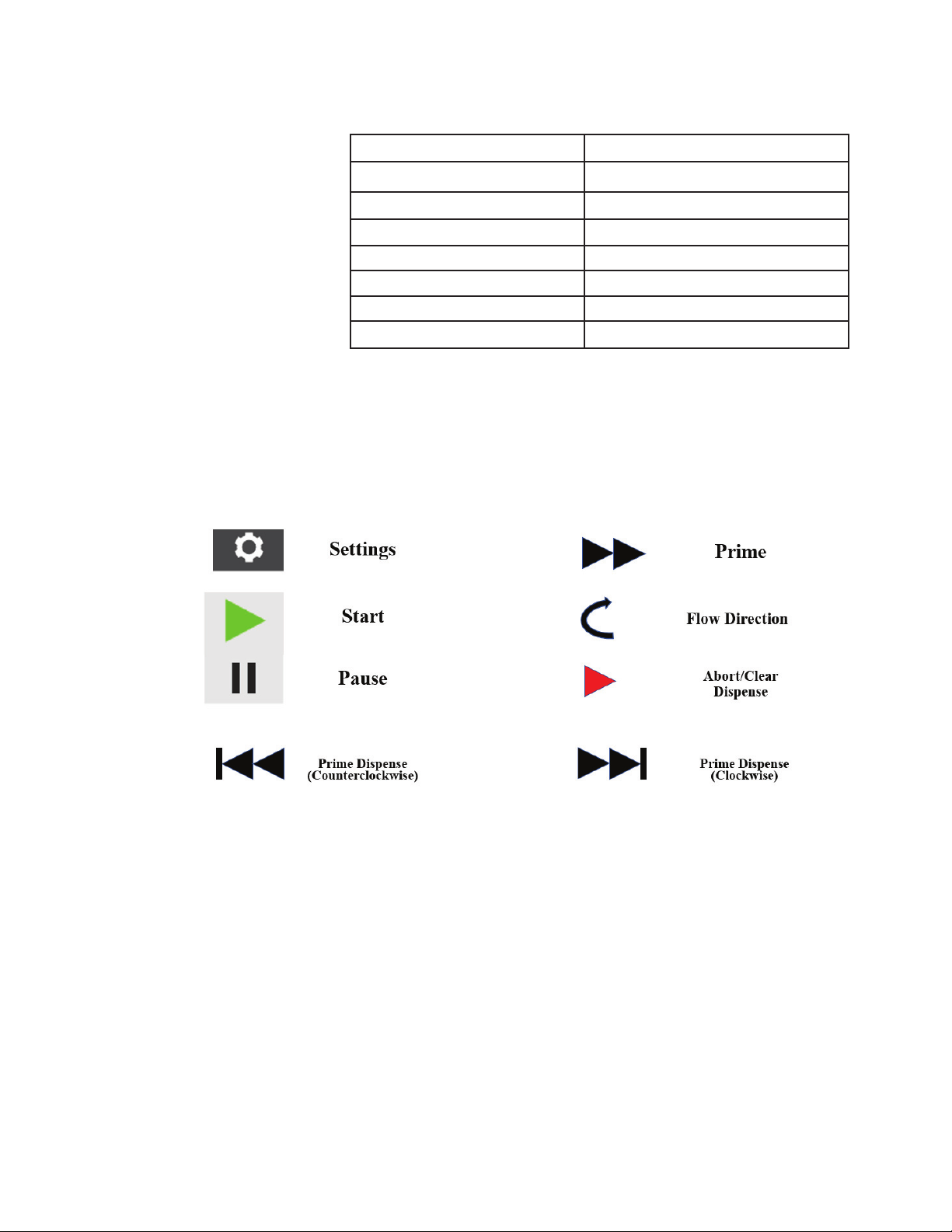
Touchscreen Icons
Component Rating
Power supply (input voltage rating) 115V / 230V
Power supply (average current draw) 450 mA
External microSD memory 32 GB of storage
Plastic FDM (ABS plastic)
Controller 480 x 272 pixels, LED backlight 300 nits
Operating Temperature 0 °C to 40 °C (32 °F to 104 °F)
Dimensions 6.75in. x 5.49in. x 3.31in
Masterflex2-2 MASTERFLEX® Flow Controller
Page 11
Section 2
Basic Setup & Settings
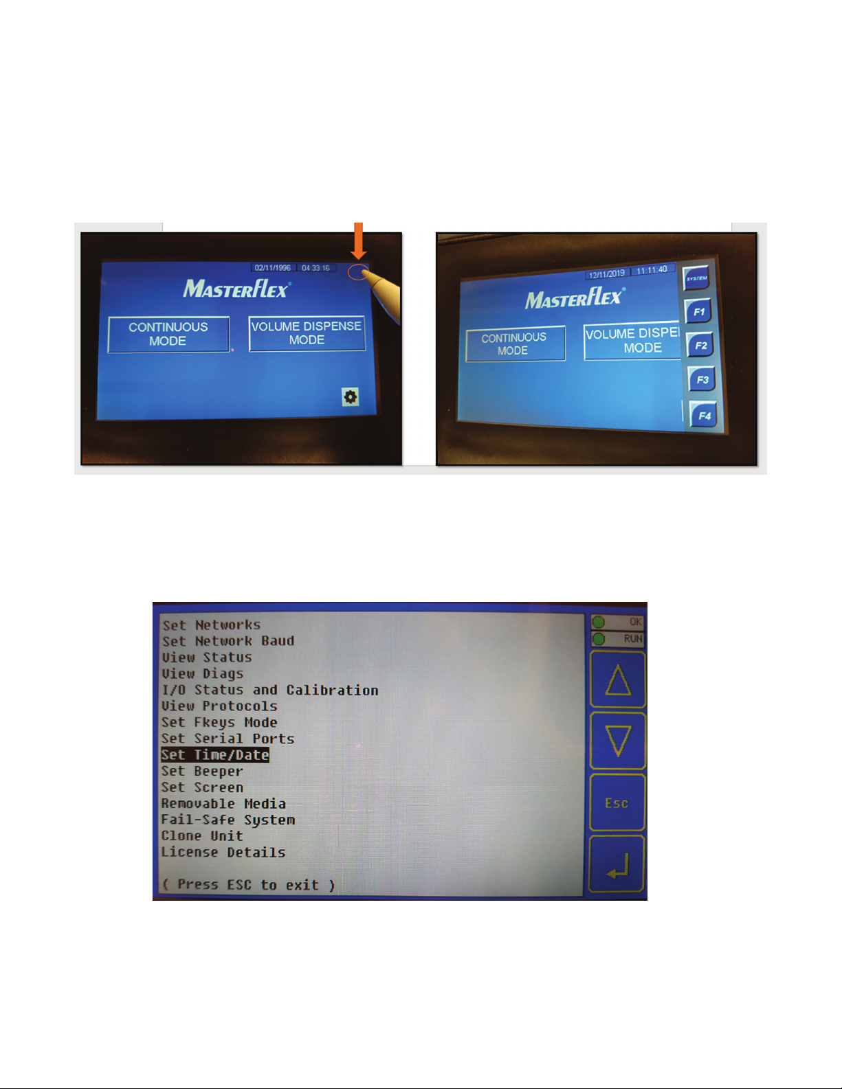
Getting Started
1. To access the controller System menu, tap on the upper right-hand corner of the main.
2. Tap on the SYSTEM icon to access the system menu options. Use the Up/Down arrows to cycle through the
configurable setting. Highlight SET Time/Date and tap on the Enter icon to access the setting. Highlight SET
Beeper to disable or enable the beeper sound. It is recommended not to change other available setting options.
Setting Time, Date, and Sound
Masterflex 2-3MASTERFLEX® Flow Controller
Page 12

Section 2
Basic Setup & Settings
Connecting and Configuring a Flow Sensor
1. Place tubing inside cavity of ultra-sonic sensor. Tubing should fit with a slight interference between
cavity openings. Only use tubing sizes matched to the flow sensor opening.
2. Close ultra-sonic sensor lid down, you might feel some slight pressure in closing lid, make sure flow direction
arrow is pointing in the direction of the out-let flow.
Masterflex2-4 MASTERFLEX® Flow Controller
Page 13

Basic Setup & Settings
3. Connect and tighten the M8 communication cable from the flow controller onto the ultra-sonic sensor.
Section 2
4. Depending on Pump model, use the supplied 9-pin or 25-pin interface adapter to establish communication
between the pump and the flow controller.
Masterflex 2-5MASTERFLEX® Flow Controller
Page 14

Section 2
Basic Setup & Settings
5. Connect the RJ45 cable to the back of the flow controller and the other end to the proper interface adapter
for pump control.
6. Connect the male side of the interface adapter cable to the female remote interface port of the pump.
Masterflex2-6 MASTERFLEX® Flow Controller
Page 15

Basic Setup & Settings
7. Connect the 24-volt power supply adapter plug to the side of the flow controller. Press the power switch to
turn on flow controller unit.
8. After Powering up the flow controller. In the Main screen, click/touch the Gear wheel option menu icon.
Section 2
9. Click on the I/O config icon.
Masterflex 2-7MASTERFLEX® Flow Controller
Page 16

Section 2
Basic Setup & Settings
10. In the Meter 33501 option, select the Sensor size in the field next to the Meter 33501 that is currently
connected to the flow controller. This will change the flow capacity (EUL to EUH). Also, make sure the Flow
Signal is set to: Source ANALOG and NOT RS485.
NOTE: Sensor size used in this example is a 35.
Masterflex2-8 MASTERFLEX® Flow Controller
Page 17

Section 3 Operation
Mode Selection Screen
The Mode Selection screen allows access to the two operation modes (Continuous and Volume Dispense
Mode) The Mode Selection screen can be accessed anytime by tapping the MAIN icon.
Masterflex 3-1MASTERFLEX® Flow Controller
Page 18

Section 3
Operation
Continuous Mode
In Continuous Mode the flow controller will control the pump to maintain a selected flow rate by the user.
Continuous Mode – Continuous Mode Run Screen
The flow rate value read by the
flow sensor.
Masterflex3-2 MASTERFLEX® Flow Controller
Page 19

Continuous Mode – Continuous Mode Setting Screen
Section 3
Operation
1. Continuous Mode: Returns user to main continuous mode run screen.
2. Flow Total: Enable or Disable the current cumulative volume of fluid that has been pumped.
3. Flow Total: Resets the cumulative volume to zero.
4. Ramp Target SP: Set point target flow rate.
5. Ramp Target Time: The ramp-up time to reach the Ramp Target SP.
6. Ramp Elapsed Time: Time taken to reach Ramp Target SP.
7. sp ramp done: Enables or disables the Ramp Target SP feature.
Masterflex 3-3MASTERFLEX® Flow Controller
Page 20

Section 3
Operation
Continuous Mode – Start a Set Point Flow
1. Start by configuring your Pump into remote Current Input Mode 4mA – 20mA (see your pump user manual for
instructions for remote input current mode)
2. Establish your Setpoint flow by clicking on the Setpoint icon. Enter your flow set point.
NOTE: Setpoint will be in mL/min.
3. Click on Output % and change to 10 %.
Masterflex3-4 MASTERFLEX® Flow Controller
Page 21

4. Click on the Green Start triangle to start the pump flow. You will notice that the middle circular-direction
arrow is spinning, this is indication that that the pump is working, and flow has begun.
5. Click on the MANUAL icon to toggle to AUTO. This will allow the flow controller to control the rate of speed
of the pump to automatically maintain the desired SETPOINT.
Section 3
Operation
NOTE: Once AUTO icon has been toggled the flow controller will control the flow rate Output % to best
regulate the SETPOINT flow rate. AUTO can ONLY be toggled when pump is running.
Masterflex 3-5MASTERFLEX® Flow Controller
Page 22

Section 3
Operation
6. To Enable or Disable Flow Total (cumulative volume) tap on the gear wheel in the Continuous mode screen.
Flow Total can be Enable or Disable and Flow Total can be reset.
Masterflex3-6 MASTERFLEX® Flow Controller
Page 23

Volume Dispense Mode Operation
In Volume Dispense Mode, the flow controller will run the pump at a selected flow rate until a selected volume
set point has been pumped. When a selected set point volume has been pumped the flow controller will stop
the pump automatically.
Volume Dispense Mode – Volume Dispense Run Screen
Section 3
Operation
Masterflex 3-7MASTERFLEX® Flow Controller
Page 24

Section 3
Operation
Volume Dispense Mode – Volume Setting Screen
l “Charging” “Approaching” l
Volume of fluid Dispense
1. DispenseApproachTotalSP: The dispense volume amount in which you would like to start the
“Approaching” (ramp down) portion of dispense.
2. DispenseFlow SP: The “charging” (starting) flow rate of volume amount to dispense.
3. DispenseApproachFlow SP: The flow rate of the “Approaching “(ramp down) portion of dispensed volume.
4. Initial Pump Speed: Speed percentage of how fast the pump motor will run during initial ramp-up.
5. PrimeSpeed: The speed percentage of how fast the pump motor will run during a clockwise prime.
6. PrimeTime: The duration time of a prime in the clockwise direction.
7. RetractionSpeed: The speed percentage of how fast the pump motor will run during a counterclockwise
prime.
8. RetractTime: The duration time of a prime in the clockwise direction.
9. Volume Dispense Mode: Returns user to volume dispense run screen.
10. Repeat Dispense Settings: menu settings for repeat batches.
11. Auto prime off: Automatically prime flow after each dispense, in the clockwise direction.
12. Auto retract off: Automatically prime flow after each dispense, in the counterclockwise direction.
Masterflex3-8 MASTERFLEX® Flow Controller
Page 25

Volume Dispense Mode – Repeat Dispense Setting Screen
Section 3
Operation
1. Volume Dispense Mode: Returns user to volume dispense run screen.
2. DispenseCountSP: The number of batches to dispense.
3. Off Time SP: The countdown of the set interval time between the next dispense batch.
4. Enable Repeat Dispense: Enables or disables auto dispenses.
5. ResetDispenseCount: Resets the batch total to zero.
6. Reset Off Timer: Resets the countdown time to zero.
Masterflex 3-9MASTERFLEX® Flow Controller
Page 26

Section 3
Operation
Volume Dispense Mode – Start a Volume Dispense
1. Start by configuring your Pump into remote Current Input Mode 4mA – 20mA (see your pump user manual for
instructions for remote input current mode)
For this example, our volume amount to dispense will be 250 ml at an initial (charge) flow rate of 400 ml/min. When
the dispense amount reaches 200 ml (approach), the flow rate will change to 25 ml/min for the remainder of the
dispense.
3. Tap on the Gear setting icon to access the setting menu.
4. Tap on DispenseApproachTotal SP and set it to 200.
5. Tap on DispenseFlowSP and set it to 400.
6. Tap on DispenseApproachFlow SP and set it to 25.
Masterflex3-10 MASTERFLEX® Flow Controller
Page 27

Section 3
Operation
7. Tap on Volume Dispense Mode to return to the main screen.
8. Tap on the green start icon to begin dispensing.
9. The Dispense State will now change to “Charging” unit the fluid dispensed amount reaches 200 ml and the
flow rate is at a controlled 400 ml/min.
Masterflex 3-11MASTERFLEX® Flow Controller
Page 28

Section 3
Operation
10. When the Dispense Total amount reaches 200 ml. The Dispense State will change to “Approaching” and
the flow rate will start ramping down to 25 ml/min.
11. When the Dispense is complete, the Dispense state will change to “Charge Done”. The user can begin
another dispense by triggering the footswitch or by tapping on the start icon unless repeat dispenses have
been enabled.
Masterflex3-12 MASTERFLEX® Flow Controller
Page 29

Data Logging Setup
1. The user can control the data logging by using the settings icon on the main screen to call up the Main
Settings menu:
Setting Icon
Figure 1: Main Screen
Section 3
Operation
Historian Set Up
Figure 2: Main Settings Screen
2. Pressing the Historian Setup button brings up the following screen:
Masterflex 3-13MASTERFLEX® Flow Controller
Page 30

Section 3
Operation
Toggles Historian On or Off
Enter the logging frequency
in seconds, e.g. 0.1 seconds
is 10 times per second, 300
seconds is once every 5
minutes.
Blinks each time data is
recorded automatically; user
can press button at any time
to record an extra set of
readings.
Figure 3: Historian Setup Screen
3. The data is stored in the HISTDATA folder of the 32GB microSD card in the controller. A new file is created
every day with the following file naming convention:
YYMMDD.CSV
Where YY represents the last two digits od the current year
MM represents the current month
DD represents the current day
.CSV is the file extension for a comma separated variable file.
The following variables are logged to the 32GB microSD card installed in the X4 controller supplied with the
system:
FlowPV: the current flow rate reported by the flow transmitter, ml/min
PID_sp[0]: the current setpoint for the flow controller the user has entered, ml/min
PID_ManOut[0]: the current output to the pump, 0-100%
FlowIntegPV: the integrated flow from the flow meter (since it was last reset), mls
FlowCommErrorCount: the total number of consecutive communication errors between the flow transmitter
and the X4 flow controller.
Masterflex3-14 MASTERFLEX® Flow Controller
Page 31

4. These variables are stored in a time stamped CSV (comma separated variable) file compatible with many
programs such as Microsoft Excel, which can be used to plot and further analyze the data.
The format of the data in the CSV file is a header row followed by date and time stamped data, similar to the
following:
Date,Time,FlowPV,PID_sp[0],PID_ManOut[0],FlowIntegPV,FlowCommErrorCou
06/30/2019,17:26:37,0,700,0,0,89
06/30/2019,17:26:42,0,700,0,0,108
06/30/2019,17:26:47,0,700,0,0,127
When the .CSV file is opened by Excel:
Section 3
Operation
Note that in the above display the FlowCommErrorCount is increasing because no flow transmitter is connected to the system.
5. The SD card can be physically removed from the controller and inserted into the supplied SD to mircoSD
card adapter to transfer files to a laptop. If the SD card is removed from the controller data will continue to
be stored in a buffer and will automatically be appended to the data file when the SD card is reinstalled in
the controller. The buffer will likely last for about an hour before data is lost, but the time depends on the
data logging frequency set by the user.
Masterflex 3-15MASTERFLEX® Flow Controller
Page 32

Section 3
Operation
Note: the user may make a copy of the currently displayed screen using the [F4] button on the fly-in buttons on the controller screen. The fly-in buttons appear by pressing the upper right hand corner of the controller screen. After [F4] is pressed,
the screen will be copied after a 3 second delay. The delay is provided to allow the user to touch the screen in another
area to remove the fly-in buttons from the screen before it is captured.
F4 fly-in button to
capture screen.
Figure 4: Screen captured with fly-in buttons shown
6. The display files are captured in .jpg format so they can be viewed or pasted into many applications, such as
Microsoft Word.
The .jpg files are stored in the following directory structure of the microSD card of the controller:
\DISPLAYS\YYMMDD\HHMMSS\DISPnnnn.jpg
Where DISPLAYS is a directory in the root directory of the microSD card
YYMMDD is a directory where
YY is the last two digits of the current year
MM is the current month
DD is the current day
HHMMSS is a directory where
HH is the current hour
MM is the current minute
SS is the current second
DISPnnnn.jpg where nnnn is the current display number shown the screen.
This directory structure allows the user to find and keep a time stamped path to any captured screen.
MASTERFLEX® Flow Controller
3-16 Masterflex
Page 33

Section 4 Product Assistance
Product Return
Technical
Assistance
To limit charges and delays, contact the Manufacturer or authorized seller for
authorization and shipping instructions before returning the product, either
within or outside of the warranty period. When returning the product, please
state the reason for the return. For your protection, pack the product carefully
and insure it against possible damage or loss. Any damages resulting from
improper packaging are your responsibility.
If you have any questions about the use of this product, contact the
Manufacturer or authorized seller.
Masterflex 4-1MASTERFLEX® Flow Controller
Page 34

®
US & Canada only
Toll Free 1-800-MASTERFLEX | 1-800-637-3739
Outside US & Canada
1-847-549-7600 | 1-847-381-7050
*EN809 manufactured by:
Cole-Parmer Instrument Company
28W092 Commercial Avenue, Barrington, IL 60010
techinfo@masterflex.com | www.masterflex.com
 Loading...