

Page 1
OPERATING MANUAL
Composite Sampler
07580-00
& accessories
Model No.
Cole-Parmer Instrument Co.
1-800-MASTERFLEX (627-8373) (U.S. and Canada only)
11 (847) 549-7600 (Outside U.S.) • (847) 549-7600 (Local) • www.masterflex.com
Barnant Company
1-800-637-3739 (U.S. and Canada only)
11 (847) 381-7050 (Outside U.S.) • (847) 381-7050 (Local) • www.barnant.com
A-1299-1015
Edition 01-11-11-02
Page 2

TABLE OF CONTENTS
Title Page
SAFETY PRECAUTIONS......................................................3
INTRODUCTION
General..................................................................................4
Suction Lift............................................................................4
Scope ....................................................................................4
SETUP
Unpacking ............................................................................5
Assembly ..............................................................................5
Tubing Selection ..................................................................5
INSTALLATION
Site Requirements................................................................5
Power Requirements ..........................................................5
DESCRIPTION
Functional Description ........................................................6
Wetted Parts ........................................................................6
Controls, Indicators and Connectors ................................6
Familiarization System Features ........................................7
INITIAL OPERATION
System Boot-up Internal Battery........................................8
System Boot-up External Power ........................................9
Battery Charging................................................................10
Setting Time and Date ......................................................10
Security ..............................................................................10
OPERATION
Description of Programming ............................................11
Starting & Stopping Program............................................11
Menu....................................................................................12
Navigation ..........................................................................14
GLOBAL SETTINGS
General................................................................................14
Global Settings Tour ..........................................................14
VIEW/EDIT PROGRAMS
General................................................................................19
Program Menu Tour ..........................................................19
SAMPLING PROGRAM MENU OPTIONS
General................................................................................22
Program Start ....................................................................22
Sample Volume ..................................................................23
# of Contact Closures........................................................24
Default Program Settings..................................................25
Save Program ....................................................................25
Hot Keys..............................................................................26
CALIBRATING THE SYSTEM
General................................................................................26
Minimum Sample Size ......................................................26
Required Equipment..........................................................26
Calibration Procedure........................................................26
Previous Calibrations ........................................................27
CYCLING THE SYSTEM ....................................................27
MAINTENANCE
Sample Reservoir ..............................................................27
Tubing..................................................................................27
TROUBLESHOOTING
General................................................................................28
Error/Status Messages & Solutions................................28
USER REPLACEMENT PARTS SERVICING
Internal Battery Replacement ..........................................29
Motor Brush Replacement/Check....................................30
USER REPLACEMENT PARTS ..........................................31
SPECIFICATIONS ..............................................................32
WARRANTY ........................................................................33
PRODUCT RETURN ..........................................................33
TECHNICAL ASSISTANCE ................................................33
ACCESSORY OPERATING INSTRUCTIONS
07571-50 Automotive Power Adapter ..............................34
07571-52 & -54 Auxiliary Power-Pak................................35
07580-60 Remote Contact Closure Cable ......................38
07580-65 RS-232 Adapter..................................................38
2
NORPRENE, PHARMED, TYGON—Reg TM Norton Co.
WINDOWS—Reg TM Microsoft Corp
Trademarks bearing the ® symbol in this publication are registered in the U.S. and in other countries
Page 3

3
SAFETY PRECAUTIONS
DANGERS: NEVER apply AC voltages directly to the EXTERNAL POWER INPUT receptacle on the front
panel. The application of AC voltages can result in injury and death of the operator and
destruction of the unit. Use only the AC/DC Universal Power Supply/Converter supplied
with the unit to power unit from an AC source.
NEVER short or connect the terminals of the battery terminals together. Shorting of the
battery terminals causes rapid internal heating of the battery resulting in the explosion of
the battery and severe injury to or the death of the operator.
The AC/DC Universal Power Supply/Converter is rated for INDOOR USE ONLY. DO NOT use
the AC/DC Power Supply/Converter in an outdoor environment to either charge the battery
or power the drive. Electrical shock, severe injury and/or death are possible if this warning
is ignored.
DO NOT BURN OR INCINERATE THE BATTERY. THE BATTERY MAY EXPLODE CAUSING
SEVERE INJURY OR DEATH OF THE PERSONNEL IN THE AREA. (Dispose of the old battery
by recycling.)
CAUTIONS: Do not reverse the connections to the battery. If the battery connections are reversed,
damage to the unit will occur.
Fully charge the unit before using for the first time. Damage to the internal battery can result
if the battery is in a fully discharged state and operation of the unit is attempted.
Immersion or submersion of the unit will result in improper operation and possible damage to
the unit.
Use of pump heads, tubing sizes and formulations other than those specified in this manual,
or the mounting and use of two or more pump heads concurrently will result in improper
operation and possible damage to the unit.
WARNINGS: Tubing breakage may result in fluid being sprayed from the pump. Use appropriate measures
to protect the operator and equipment.
Turn drive off, remove all the power to the unit, including the AC/DC Power Supply/Converter,
Automotive Power Adapter or other external power source if present before removing or
installing pump head or tubing. This will help prevent accidental activation of the drive
mechanism so fingers or loose clothing will not get caught in the pump drive mechanism.
WARNING: PRODUCT USE LIMITATION
This product is not designed for, nor intended for use in, patient-connected applications, including, but not
limited to, medical and dental use and, accordingly, has not been submitted for FDA approval.
Page 4
4
INTRODUCTION AND GENERAL DESCRIPTION
GENERAL
The Masterflex®E/S™Composite Sampler is a DSP controlled,
portable, self-contained, programmable peristaltic pump
system designed to meet EPA, NPDES guidelines for the
sampling of storm and waste water.
The Masterflex
®
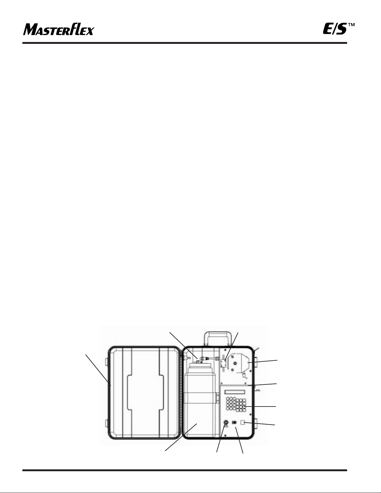
E/S™Composite Sampler as shown in Figure
1, consists of an exterior housing, a controls console which
contains the internal power source, pump drive system and
system controls, a Masterflex
®
L/S®Easy-Load®peristaltic
pump head and a sealed and vented sample reservoir. The
drive system is capable of operating one Masterflex
®
L/S
®
Standard®, L/S®Easy-Load® or L/S® PTFE pump head.
The Masterflex®E/S™Composite Sampler is current limited,
protected from reverse power supply polarity and transient
voltages.
You may operate the Masterflex
®
E/S™Composite Sampler on
the internal battery, an external 12V DC source or indoors
using the 115V AC or 230V AC with the AC/DC Universal
Power Supply/Converter supplied with the unit.
The system features a built-in spill-proof gel battery and
recharging system allowing the unit to be recharged from an
AC power source using the supplied AC/DC Universal Power
Supply/Converter or from an automotive 12V DC electrical
system if used with the Automotive Power Adapter accessory.
It is designed and programmed to accept, control and power
one Masterflex
®
L/S®Easy-Load®, Standard or PTFE Tubing
pump head for fluid transfer and sampling in the field.
The unit is housed in a high visibility, protective polyethylene
housing. The control panel and the drive controls have an
environmental protection rating of IP56.
When closed and latched, the drive will float for a minimum of 30
minutes if dropped into a lake or stream to allow recovery of the unit.
SUCTION LIFT
The Masterflex®E/S™ Composite Sampler is capable of lifting
a sample of water up to twenty-five (25) feet vertically. This
capability is called suction lift and is measured from the
surface of the liquid to the pump head.
If the liquid to be sampled has a viscosity or density greater
than water, this lifting capability is reduced or diminished.
This lifting capability is also diminished as altitude above
sea level increases.
SCOPE OF THE MANUAL
This manual contains instructions for installing, setting up,
programming, operating and maintaining the sampling
system. It is intended for use by technicians and operators
as well as maintenance personnel. The TROUBLESHOOTING
section contains a list of possible problems, their probable
causes, and actions to take to remedy each problem.
Instructions for replacing user-serviceable parts and a list of
parts that can be ordered are included.
The ACCESSORIES section lists all available accessories for
the Masterflex
®
E/S™Composite Sampler.
EXTERIOR
HOUSING
LEVEL
SENSOR
KEYPAD
ON/OFF 0-1
STATUS
SWITCH
EXTERNAL
POWER IN
RECEPTACLE
RS-232
CONNECTOR
SAMPLE
RESERVOIR
FLOW
DETECTOR
MASTERFLEX
EASY-LOAD
PERISTALTIC PUMP
CONTROL
CONSOLE
FIGURE 1
Page 5

5
SETUP
UNPACKING
Care has been taken in the packaging of the Masterflex®E/S
™
Composite Sampler to protect it in transit to its final destination.
After opening the carton, save the packing material until proper
product operation has been verified.
The Masterflex
®
E/S™Composite Sampler consists of the
following items:
(1) Sampling Unit
(1) AC/DC Universal Power Supply/Converter
(1) Sample Line Tubing Connector
(2) Keys for the locking latches
(1) 25 feet of Masterflex
®
L/S®24 size peroxide-cured
silicone tubing
(1) Operator's Manual CD
(1) Warranty Card
ASSEMBLING
Unit is shipped fully assembled and plumbed with Masterflex
®
L/S® 24 size silicone peroxide-cured tubing. The operator only
needs to connect an external sample line using the supplied
tubing connector into Sample Line Inlet bulkhead connector
shown in Figure 2.
TUBING SELECTION
The flow rate at which a sample can be taken is dependent
on the tubing size, tubing material and the height the sample
must be raised to enter the sample reservoir. The purity of
the sample is dependent on the formulation of the tubing
material. The Composite Sampler is supplied with L/S
®
24
size tubing made of peroxide cured silicone resins. The tubing
supplied with the unit has been selected based on its purity
versus flow and lift performance. Optimum lift and flow
performance can be had by using Tygon
®
LFL or Lab tubing.
See Table 1 for other tubing materials and sizes available for
operation with the Composite Sampler.
INSTALLATION
SITE REQUIREMENTS
The E/S Composite Sampler is designed to operate in most
outdoor conditions. Ensure that the work area temperature
range is between 1°C to 50°C (39°F to 122°F) and that the
relative humidity remains between 10% and 90%.
Position the sampler in an upright position with the carrying
handle at the top of the case (as shown), preferably on a firm
level surface, adjacent to the source to be sampled. The
sampler may also be suspended or attached to a vertical
support using the D-rings at the top of the exterior housing.
POWER REQUIREMENTS:
The Masterflex®Composite Sampler is internally powered by a
12 V sealed gel battery. The unit may also be operated or
charged in an outdoor environment using the Automotive
Power Adapter Accessory 07571-50 Auxiliary Power Pack
07571-52 or 07571-54, or any DC source supplying 11-18 volts.
Sampler can be operated or charged indoors from a 115
(90-130) VAC or 230 (180-260) VAC 50/60 Hz incoming power
using the AC/DC Universal Power Supply/Converter (supplied).
DANGER: NEVER apply AC voltages directly
to the EXT PWR IN receptacle on
the front panel. The application of
AC voltages can result in injury
and death of the operator and
destruction of the unit. Use only
the AC/DC Universal Power Supply/
Converter supplied with the unit to
power unit from an indoor AC
source.Fully charge the unit before
using for the first time. Damage to
the internal battery can result if the
battery is fully discharged and
operation of the unit is attempted.
Tubing formulation L/S®15 L/S®24
Silicone, peroxide-cured 96400-15 96400-24
Tygon, Lab
®
06409-15 06409-24
Tygon LFL
®
06429-15 06
429-24
PharMed
®
06485-15 06485-24
TABLE 1 Tubing Materials
Page 6

6
DESCRIPTION
FUNCTIONAL DESCRIPTION
The control console of the Composite Sampler provides the
operator interface for programming, control and charging of the
sampling system. The DSP in the control console scans the
keypad, communicates to the display, communicates with the
integral pump drive, assesses the state of and controls
charging of the battery.
The system is preprogrammed with one (1) fluid transfer
program and five (5) sampling programs. All of the factorysupplied sampling programs can be modified by the operator
and saved without modifying or destroying the factory
supplied programming. The factory supplied programming
and operational parameters are stored in non-volatile flash
memory within the DSP controller.
Program options and instructions from the operator are
stored in non-volatile memory consisting of an EEPROM
which supplements the flash memory of the DSP.
CONTROLS, INDICATORS AND
CONNECTORS
All the controls, connectors, and indicators on the controls
console and exterior housing are shown in Figure 2 and 3.
Table 2 lists all of the operator controls and indicators.
WETTED PARTS
All parts in direct contact with the sample being taken are
considered wetted parts. The following is a listing of the
wetted parts and their associated materials.
Sample intake tubing: Unit is supplied with
1
⁄4" ID 25 feet of
Masterflex
®
L/S®24 size peroxide-cured silicone tubing.
Sample intake tubing connectors: Delrin®acetal co-polymer
T ubing: Masterflex®L/S®24 size peroxide-cured Silicone
tubing.
Flow detector: PVC and stainless steel
Flow detector tubing connectors: polycarbonate and Viton
®
Discharge tubing: Masterflex®L/S®24 size peroxide-cured
silicone tubing.
Discharge tubing fittings: Delrin
®
acetal co-polymer
Sample reservoir: HDPE (high density polyethylene)
Sample reservoir cap: polypropylene
Breather vents, sample reservoir: medical grade ABS/Teflon
®
SAMPLE
LINE INLET
REMOTE CONTACT
CLOSURE
CONNECTOR
RS232
CONNECTOR
EXTERNAL POWER IN
RECEPTACLE
11-18VDC
ON-OFF
0-1/ STATUS
SWITCH
FIGURE 2
Page 7

7
Control or indicator Description and function
0-1/ STATUS Use to turn the unit ON, OFF, check unit status or awaken unit from an inactive mode
DISPLAY 24 character by two-line LCD that displays all menus needed for programming and operating
the system.
MENU Use to access the menu.
Selection arrow keys Use to navigate menu options shown on the display.
Numeric keypad 0-9 Use for numeric entry.
START/STOP Use to initiate program or to stop a program which is running.
CANCEL Cancels any changes that were made to the current menu selection and returns to previous menu
ENTER Accepts the selected item and moves down to the next menu level. If there is not a lower menu
level, it will return to the top level for the selected item.
CLOCK Used to set date and time. The date is displayed in a MM:DD:YY format. The time format is a
24hour clock displayed in a HH:MM:SS..
TIME Used access the time settings in the loaded program.
SAMP. VOL Used to access the sample volume parameter in the loaded program without going through the
menu.
LIFT HEIGHT Used to access the lift height parameter in the loaded program without going through the menu
CYCLE TEST Used to verify unit operation in the field.
CAL Used to verify and calibrate unit in the field for accurate sample delivery.
TABLE 2 Operator Controls and Indicators
FIGURE 3
FAMILIARIZATION WITH
SYSTEM FEATURES
The system has unique features with which the operator needs to
become familiar during the course of system operation. Understanding
the features will enable the operator to know if the system is
operating properly and effectively. These features are as follows:
1. Automatic Power-Up: Any time an external power source is
connected to the EXT POWER IN receptacle located on the front
of the control console, the system will power up and go through a
boot up routine or display a system message as to system status.
If no action is taken, the system will charge the battery.
2. Automatic Power Conservation: If the system is not implementing an internal command or the operator has not pressed a
key on the control console for 10 minutes the system to conserve
power will POWER DOWN. The LCD display will display a message
for 5 seconds:
POWERING DOWN
Page 8
8
After which the display will blank. If an external power source
is connected at the time, the battery will continue to charge
while the display is blank. If a sampling program was running
or in process at the time of power down the system will
continue to run the program. The display panel will show a
message when the unit starts to take a sample and show
the time until the next sample is to be taken. The display will
remain active for an additional 5-10 seconds before returning
to a powered down state.
If the display panel is not active, press the 0-1/STATUS key
on the control console to awaken the system.
3. Automatic Battery Charging: System will automatically
charge the internal battery any time an external power source
such as the AC/DC Universal Power Supply/Converter or
Automotive Power Adapter is plugged into the EXT PWR IN
receptacle. The rate at which the internal battery is charged
will vary with other system operations. Once the battery is
fully charged, the integral battery charging circuit will place
the battery on a floating or maintenance charge to maintain
the battery in a fully charged state.
4. Automatic Purging: The system will automatically purge
the sample intake line prior to the taking of any sample or the
occurrence of a rinse cycle. This is to ensure that the sample
inlet line is free of any obstructions or debris.
5. Glow-In-Dark Keypad: The keypad is printed with
phosphorescent pigments. These pigments will glow for up
to 20 minutes if exposed to ultraviolet radiation from the sun
or a krypton flashlight. This feature is helpful in low ambient
light conditions. The LCD display is backlightable and when
used with keys that glow in the dark, this lessens the need for
external lighting in dim and dark areas.
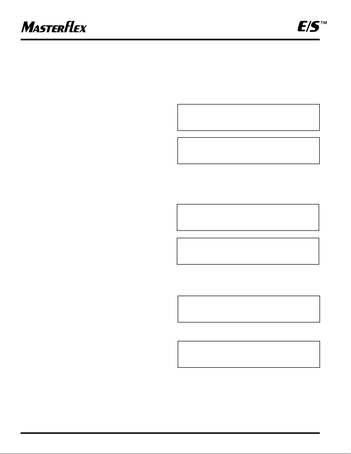
INITIAL OPERATION
SYSTEM BOOT—INTERNAL BATTERY
Press the 0-1/STATUS button on the control console. The
LCD display will activate and display the following messages:
System will power up the drive system to place the internal
battery under load and verify its condition.
The LCD panel will display one of the following messages,
depending upon battery condition.
If the battery is fully charged or you pressed cancel when
notified the battery is low, the system will complete boot-up
and display the following on the LCD screen:
If the message displayed is:
The system should not be operated until the battery has been
charged or an external power source has been connected to
the unit. Proceed to the BATTERY CHARGING section of the
manual on page 10.
SAMPLER ON VERSION X.X
CHECKING BATTERY
PRESS CANCEL TO QUIT
BATTERY FULLY CHARGED
BATTERY IS LOW
CHARGING IS RECOMMENDED
SAMPLER SYSTEM READY
HH:MM:SS MM/DD/YYYY
BATTERY IS VERY LOW
MUST CHARGE BATTERY!
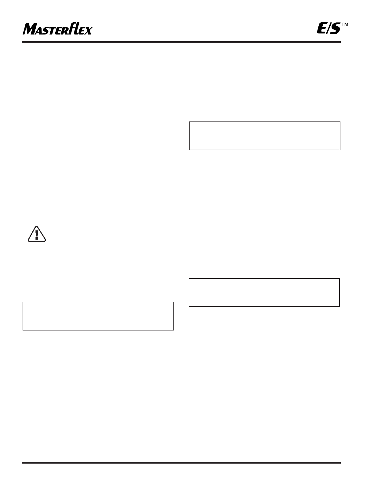
Page 9

SYSTEM BOOT—
EXTERNAL POWER
Open the exterior housing, connect the AC/DC Universal
Power Supply/Converter into the EXT PWR IN receptacle on
the front. Then connect the AC plug into an AC receptacle.
The system will come on automatically. The first screen displayed on the LCD panel will be:
This will be followed by another screen:
Remove the plug from the EXT PWR IN receptacle on the
control console. LCD will change to read:
The system will power up the drive system to place the
internal battery under load and verify its condition. After the
drive system has stopped, you may reconnect the external
power to the EXT PWR IN receptacle. The LCD panel will
display one of the following messages, depending upon
battery condition.
If the battery is fully charged or you pressed cancel when
notified the battery is low, the system will complete boot-up
and display the following on the LCD screen:
If the message displayed is:
The system should not be operated until the battery has been
charged. Proceed to the BATTERY CHARGING section of the
manual on page 10.
SAMPLER ON VERSION X.X
REMOVE EXT PWR TO CHECK
BATTERY—CANCEL TO SKIP
CHECKING BATTERY
PRESS CANCEL TO QUIT
BATTERY IS FULLY CHARGED
BATTERY IS LOW
CHARGING IS RECOMMENDED
BATTERY IS VERY LOW
MUST CHARGE BATTERY!
SAMPLER SYSTEM READY
HH:MM:SS MM/DD/YYYY
9
Page 10
10
SAMPLER SYSTEM READY
HH:MM:SS MM/DD/YYYY
BATTERY CHARGING
The Composite Sampler is equipped with an internal four
state battery charger capable of diagnosing and automatically
charging the internal battery. The operator only needs to
connect the AC/DC Universal Power Supply/Converter or
Automotive Power Adapter accessory. The sampler system
will automatically power up and begin charging the battery.
After 10 minutes the LCD display on the control console will
power down, going blank. The battery will continue to charge
until it has reached is full potential. Once the battery is fully
charged, the battery will be placed on a float or maintenance
charge until the external power source is disconnected.
The system may run or be programmed while the unit is
charging. Battery charging will continue in the background
while other operations are taking place. Allow a minimum of
8 hours to fully charge the battery from a fully discharged
state with no other operations occurring. During battery
charging all functions of the sampler are operational.
WARNING! The AC/DC Power Supply/Converter
is rated for INDOOR USE ONLY.
DO NOT use the AC/DC Power
Supply/Converter in an outdoor
environment to either charge the
battery or power the drive. Electrical
shock, severe injury and/or death is
possible if this warning is ignored.
SETTING THE TIME AND DATE
Press the keypad's CLOCK key. The display will read:
TIME
The clock used in the Composite Sampler is a 24-hour clock,
does not use an AM or PM notation and shows the time in
an HH:MM:SS format. The clock displays 12:00 AM midnight
as 00:00:00 (the starting point of the clock), 6:00:00 AM as
06:00:00, 12:00:00 PM (or noon) as 12:00:00 and 6:00 PM
as 18:00:00.
If a sample was taken at 3:00 PM the clock will read 15:00:00.
The Composite Sampler clock was set at the factory based
upon our local time. The time is expressed as hour, hour,
minute, minute, second, second. If the current time on the
clock is correct, bypass setting the time by pressing ENTER
or CANCEL and you will be taken to the screen where you
may change the date. See the screen below.
If you need to correct the time shown on the clock, use the
numeric keypad to enter the current time and press ENTER.
The display will change to the date correction screen as
shown below.
DATE:
The calendar date is expressed as month, month, day, day,
year, year.
If the date is correct, press ENTER or CANCEL and you will
be taken back to the system prompt.
If you need to correct the date shown, use the numeric
keypad, enter the date and press ENTER.
EXAMPLE: To enter January 1, 2003, press 10103 on the
numeric keypad and press ENTER.
To enter December 31, 2002, press 123102 on
the numeric keypad and press ENTER.
You will then be taken back to the system prompt screen
which will now display the current time and date.
SECURITY
The Composite Sampler will be exposed to an outdoor
environment in which the operator may or may not be
present or in attendance. To protect the unit from tampering
by unauthorized individuals the sampler housing may be
locked using the two locking latches on the exterior of
the housing.
In addition a security feature has been incorporated into
the Composite Sampler to lock the keypad.
SET TIME (HR:MIN:SEC)
20:30:57 (23:59:59)
SET DATE (MON/DAY/YR)
09/21/02 (MM/DD/YY)
Page 11
11
LOCKING THE KEYPAD
The Composite Sampler keypad may be locked to ensure
that running programs are not inadvertently terminated or to
restrict access to the system. The only key which is functional
when the keypad lockout is enabled is the 0-1/STATUS key.
Pressing this key will not disable or interfere with any program
which is running. To lock the keypad, perform the following
procedure either from a system prompt or after you have
pressed the START/STOP key to start a program. The keypad
lockout cannot be enabled or disabled during programming
or the editing of a program.
1. Ensure that the control console is in a system ready prompt
or a program is running.
2. Enter 847 on the numeric keypad and press ENTER.
3. The following display appears for approximately five
seconds. The display reappears anytime a non-numeric
key is pressed and the LCD display is active.
4. To unlock the keypad, enter the same code and press
ENTER. The following display appears:
OPERATION
The unit is operated through the use of a menu system and
various hot buttons on the keypad located on the control
console face. The menus and their options are shown as words
and numbers used in everyday oral communications or
speech without the need for decryption or an additional legend.
This equipment should not be operated on a "learn as you
go" basis. Make sure to become familiar with and practice all
safety procedures presented in the SAFETY section before
operating the Composite Sampling System.
DESCRIPTION OF PROGRAMMING
The Composite Sampler can be operated using any of the
six (6) factory supplied programs through the menu system.
The five (5) sampling programs can be modified or edited and
stored for future use. Editing the factory supplied programs
and saving them as modified programs will temporarily
overwrite the factory program. The factory programs can be
individually restored to their original default settings upon
operator demand through the menu system.
NOTE: One program is always present or selected to run
whenever the unit is on. When received from the factory the
default program selected to be run is PROGRAM #1.
STARTING/STOPPING A PROGRAM
To start or stop a program press the START/STOP key.
Programs can only be started from a SAMPLER SYSTEM
READY prompt. Sampling programs can be stopped at any
time the display is active by pressing CANCEL. If the display
is inactive, press the 0-1/STATUS key to awaken the system
and then press CANCEL. The CONTINUOUS PUMPING
program can be stopped at any time. Stopping a program is
equivalent to canceling the program. Programs that have
been stopped cannot be restarted from the point at which
they were stopped. When you start the program again, it will
begin at the beginning of the program.
HINT: If the program you stopped was taking a sample, it
may be necessary to empty or clear the sample reservoir
prior to starting the program again.
CANCELING A PROGRAM
To cancel a program that has started, press the CANCEL
key. Canceling a program is the same as stopping a program
as described above. Pressing the CANCEL key does not
deselect the program selected to be run. It only cancels the
program schedule that has started.
HINT : The program will show up on the data log as a cancelled
program. If you do not want this record to appear on the data
log, clear the data log prior to starting the program again.
ACCESSING THE MENU
Operation of the system and editing programs is menu driven.
To access the menu press the MENU button on the control
console. The LCD display will show the following.
KEYPAD LOCKOUT ENABLED
KEYPAD LOCKOUT DISABLED
g GLOBAL SETTINGS
c VIEW/EDIT PROGRAMS
Page 12

12
MENU
The menu is divided into two main sections or categories: GLOBAL SETTINGS and VIEW/EDIT PROGRAMS.
GLOBAL SETTINGS
This section consists of operational parameters related to the
Composite Sampler system as follows:
• DISPLAY CONTRAST
• SAMPLING LOCATION NUMBER
• PUMP HEAD SELECTION
• TUBING SIZE SELECTION
• TUBING FORMULATION SELECTION
• RINSE CYCLES
• VOLUME UNITS
• DISTANCE UNITS
• LIFT HEIGHT
• TUBING LENGTH
• LCD BACKLIGHTING
• DATA LOGGING
• DEFAULT GLOBAL SETTINGS
VIEW/EDIT PROGRAMS
The VIEW/EDIT PROGRAMS section consists of parameters
related to the sampling programs as follows:
• SELECT HOW PROGRAM IS STARTED
• SAMPLE VOLUME
• NUMBER OF SAMPLES
• TIME INTERVAL BETWEEN SAMPLES
EQUAL OR UNEQUAL
• # OF CONTACT CLOSURES
• DEFAULT THE PROGRAM SETTING
• SAVE USER PROGRAM
See Table #3 for menu categories and selections.
Page 13

TABLE #3 MENU SELECTIONS
Defaults are shown in BOLD type or noted
13
CATEGORY SELECTION CHOICES SUB SELECTIONS
DISPLAY CONTRAST UP & DOWN ARROWS TO ADJUST
LOCATION NUMBER ENTER 0-99999999
PUMP HEAD
Easy-Load/Standard
SIZE 24
TYGON LFL
TYGON LAB
SIZE 15
SILICONE TUBING
PHARMED TUBING
PTFE TUBING PUMP
PTFE 4 MM
PTFE 6 MM
RINSE CYCLES ENTER NUMBER 0-5 Default is 0
VOLUME UNITS
MILLILITERS
GALLONS
DISTANCE UNITS
FEET
GLOBAL
METERS
LIFT HEIGHT ENTER NUMBER Default is 6 feet or 1.8 meters
TUBING LENGTH ENTER NUMBER Default is 12 feet or 3.6 meters
LCD BACKLIGHTING
NONE—POWER SAVER
BACKLIGHT ON KEY PRESS
KEY PRESS AND SAMPLING
CONTINUOUS BACKLIGHT
LOG DATA
VIEW LOG DATA
PRINT LOG DATA
CLEAR LOG DATA
CLEAR ALL LOG DATA
DON'T CLEAR LOG DATA
DEFAULT GLOBAL SETTINGS
RESET GLOBAL SETTINGS
DON'T RESET SETTINGS
PROGRAM START
DELAYED START HHH:MM (0-167.59)
REMOTE & DELAYED START HHH:MM (0-167.59)
MAINTAINED CONTACT
PULSED CONTACT
SAMPLE VOLUME ENTER NUMBER (1-9,000)
NUMBER OF SAMPLES ENTER NUMBER (1-99)
EQUAL INTERVALS HH:MM (0-99:59)
HH:MM (0-99:59)
#1 HH:MM (0-99:59)
#2 HH:MM (0-99:59)
#3 HH:MM (0-99:59)
#4 HH:MM (0-99:59)
#5 HH:MM (0-99:59)
VIEW/EDIT
TIME BETWEEN SAMPLES
UNEQUAL INTERVALS
#6 HH:MM (0-99:59)
PROGRAMS
#7 HH:MM (0-99:59)
#8 HH:MM (0-99:59)
#9 HH:MM (0-99:59)
#10 HH:MM (0-99:59)
#11 HH:MM (0-99:59)
#12 HH:MM (0-99:59)
# OF CONTACT CLOSURES
ENTER NUMBER Only appears if MAINTAINED is not
(0-9999) Default is 0 chosen under PROGRAM START/REMOTE & DELAYED START
DEFAULT PROGRAM RESET PROGRAM SETTINGS
SETTINGS DON'T RESET SETTINGS
USER PROG #1
USER PROG #2
SAVE USER PROGRAM USER PROG #3
USER PROG #4
USER PROG #5
Page 14

14
NAVIGATION
Looking at the LCD display screen below:
1. The MENU key takes you to the top level of the menu as
shown above.
2. The arrows in the first display column indicates which way
the user can go from each menu selection.
3. Solid box in second column indicates selected menu item,
empty box is an unselected menu item.
NOTE: Only one selection is allowed in each menu option.
4. UP/DOWN arrow keys on the control console move the
solid box to select a menu item and scroll the display if
more menu items are available.
5. The ENTER key accepts the selected item and moves
down to the next menu level. If there is not a lower menu
level, it will return to the top level for the selected item. For
example, if selecting a tubing material, pressing ENTER will
return back to the PUMP HEAD menu selection.
6. CANCEL key cancels any changes that were made to the
current menu selection and returns to previous menu.
7. CANCEL key will back up to previous menu level and exit
the menus when at the top level.
8. Display is 2 lines by 24 characters so only 2 lines of the
menu are seen at one time.
GLOBAL SETTINGS
GENERAL
The GLOBAL SETTINGS are not saved in memory like
multiple sampling programs. The only settings available are
those currently loaded into the non-volatile memory.
Selecting a menu option or setting using the up and down
arrow keys does not load that option or setting in memory
until the ENTER key is pressed.
Settings must be modified as necessary to suit the sampling
site and equipment used. Many of these settings may use the
default values, such as pump head selection, tubing size or
formulation. Other parameters such as lift height and tubing
length or location will vary with the sampling site and will be
changed frequently.
GLOBAL SETTINGS TOUR
The tour of the GLOBAL SETTINGS menu will take the operator
through each of the menu selection display screens. Going
through the entire menu is not necessary each time a change
to one or two GLOBAL SETTINGS parameters is made. It is
recommended that you take the tour to familiarize yourself
with all of the options and screens available.
Select GLOBAL SETTINGS by pressing the ENTER key.
The display will now show the following choices:
DISPLAY CONTRAST
Allows adjustment of the display contrast for readability.
ADJUSTING THE DISPLAY
CONTRAST
To adjust the contrast of the LCD display, select DISPLAY
CONTRAST and press the ENTER key. The following menu
will be displayed:
View the display and use the up and down arrow keys to
adjust the contrast. Press the up arrow key to increase
contrast or the down arrow key to decrease contrast. When
you have achieved the desired contrast, press the ENTER
key. This will save the contrast setting you have selected
for the display. The system will return you to the following
display.
DISPLAY CONTRAST
g DISPLAY CONTRAST
c LOCATION NUMBER
g
GLOBAL SETTINGS
c
VIEW/EDIT PROGRAMS
g
DISPLAY CONTRAST
c
LOCATION NUMBER
g
GLOBAL SETTINGS
c
VIEW/EDIT PROGRAMS
Page 15

15
Use the down arrow to select LOCATION NUMBER, the filled
in box will switch from DISPLAY CONTRAST to LOCATION
NUMBER and press ENTER. The display will change to read:
LOCATION NUMBER
Allows the input of up to a 9 digit number to identify the
sampling site. You do not have to erase or delete the number
(site identifier) that may already be there.
INPUTTING A LOCATION NUMBER
Enter the number and press ENTER. The new site
identification number will be entered and the display will
change to:
Use the down arrow to decrement the menu to and select
PUMP HEAD by pressing ENTER.
The display changes to read:
PUMP HEAD
Multiple option screens which allow the operator to select the
pump head, tubing size and tubing formulation or material.
EASY-LOAD is the default pump head supplied with the
Composite Sampler for your convenience in changing the
tubing when needed. If you intend to use the pump head
supplied with the unit press ENTER.
If you wish to use a PTFE TUBING PUMP proceed to the
description of this menu option on page 16.
The display will change to read:
Size 24 is the default tubing size. The tubing supplied with
the Composite Sampler is L/S
®
24 peroxide cured silicone
Model No. 96400-24. This tubing size will deliver an average
flow of 1,700 ml/min. @ 0 lift.
Size 15 is an alternate tubing size offered for use with the
Easy-Load
®
pump head supplied with the Composite
Sampler. This size option is offered for circumstances where
the use of L/S
®
24 in certain formulations may not be practical.
The average flow of L/S
®
15 tubing is 1,000 ml/min. @ 0 lift.
Select the appropriate tubing size and press the ENTER key.
The display will change to the tubing formulation menu.
NOTE: the display is only 2 lines, so you will only see 2
choices at one time. Remember the arrow in the first column
indicates whether there are choices above or below the ones
you are viewing.
The tubing formulations shown are available in either
SIZE 24 or SIZE 15. See Table 1 Tubing Materials in the
SETUP section of this manual for tubing model numbers.
LOCATION NUMBER
________ _(0-999999999)
c DISPLAY CONTRAST
g LOCATION NUMBER
c
LOCATION NUMBER
g
PUMP HEAD
g EASY-LOAD/STANDARD
c PTFE TUBING PUMP
g SIZE 24
c SIZE 15
c TYGON LFL TUBING
c TYGON LAB TUBING
g SILICONE TUBING
c PHARMED
Page 16

16
PTFE TUBING PUMP
This pump head is offered as an option for those sampling
applications such as toxic fluids and oily waste water where
only the use of Teflon“ tubing will perform adequately for the
application.
Use the up and down arrow keys to navigate and select the
PTFE TUBING PUMP and press ENTER. The display will
change to show the tubing sizes available for use with the
PTFE TUBING PUMP.
Selection of the tubing formulation for sizes 24 and 15 or the
selection of the PTFE tubing sizes will return the display to
read:
Use the down arrow keys to navigate and select RINSE
CYCLES and press ENTER. The display will change to read:
RINSE CYCLES
This sets the number of rinses (0-5) that the Composite Sampler
will perform prior to the taking of each sample. The default is
zero (0). The purpose of the rinse cycle is to remove or rinse
away any contaminants or residues in the sample intake lines
from a previous sampling site or cycle. The tubing will first be
purged of any fluid. Then fluid from the sampling site will be
drawn into the sample intake lines until the fluid is detected by
the flow sensor . The system will then stop and r everse the drive
to expel the fluid. This completes one rinse cycle.
To accept the default setting press either CANCEL or ENTER.
To change the number of cycles, enter the number of cycles
desired and press ENTER.
The display will change to read:
Use the down arrow key to navigate and select VOLUME
UNITS and press ENTER. The display will change to read:
VOLUME UNITS
Allows the user to select the units in which the sample will be
measured. The default is MILLILITERS. The two options are:
MILLILITERS
Displays the sample volume from 1-9000 milliliters.
GALLONS
Displays the sample volume from 0.001 to 2.377 gallons.
To accept the default press either CANCEL or ENTER. To
change the VOLUME UNITS from MILLILITERS to GALLONS,
use the arrow key to navigate and select GALLONS and press
ENTER. The display will change to read:
Use the down arrow key to navigate and select DISTANCE
UNITS and press ENTER. The display will change to read:
c PTFE 4 MM
c PTFE 6 MM
g PUMP HEAD
c RINSE CYCLES
RINSE CYCLES
0 (0-5)
c EASY-LOAD/STANDARD
g PTFE TUBING PUMP
c RINSE CYCLES
g VOLUME UNITS
g MILLILITERS
c GALLONS
g VOLUME UNITS
c DISTANCE UNITS
g FEET
c METERS
Page 17

17
DISTANCE UNITS
Allows the user to select English or metric distance measurement
units. The default is feet.
The two options are:
FEET
Displays the VERTICAL LIFT (1-25) and TUBING LENGTH
(1-99) in whole feet.
METERS
Displays the VERTICAL LIFT (0.3-7.6) and TUBING LENGTH
(.3 to 30.1) in tenths of a meter.
To accept the default press either CANCEL or ENTER. To
change the DISTANCE UNITS from FEET to METERS, use the
arrow key to navigate and select METERS and press ENTER.
The display will change to read:
Use the down arrow key to navigate and select LIFT HEIGHT
and press ENTER. The display will change to read:
LIFT HEIGHT
Sets the draw or lift height to which the sample must be lifted
to enter the sample reservoir.
This parameter allows the system to accurately calculate the
sample volume for each revolution of the pump head at a
specific height. Sample volume decreases as lift height
increases. This parameter will be expressed in feet or meters
depending upon your earlier choice of DISTANCE UNITS. The
default is 6 feet or 1.8 meters. Enter the number and press
enter. The acceptable values will be shown in parenthesis on
the 2nd line on the right side of the display.
Once you press enter the display will change to:
Use the down arrow key to navigate and select TUBING
LENGTH and press ENTER. The display will change to read:
TUBING LENGTH
Sets the length of tubing through which the sample volume
must be drawn. Setting the tubing length allows the system
to calculate the correct amount of time for purging the tubing
prior to taking a sample. This parameter will be expressed in
feet or meters depending upon your earlier choice of DIST ANCE
UNITS. The default is 12 feet or 3.6 meters. Enter the number
and press enter. The acceptable values will be shown in
parentheses on the second line on the right side of the display.
Once you press enter the display will change to:
Use the down arrow key to navigate and select LCD BACKLIGHT and press ENTER. The display will change to read:
NOTE: the display is only 2 lines, so you will only see 2
choices at one time. Remember the arrow in the first column
indicates whether there are choices above or below the ones
you are viewing.
LCD BACKLIGHT
Sets the conditions under which the display is backlit for
optimum readability. There are four choices of backlighting.
LIFT HEIGHT
6 FEET (0-25)
g LIFT HEIGHT
c TUBING LENGTH
g DISTANCE UNITS
c LIFT HEIGHT
TUBING LENGTH
12 FEET (1-99)
g TUBING LENGTH
c LCD BACKLIGHT
c NONE—POWER SAVER
g BACKLIGHT ON KEY PRESS
c KEY PRESS AND SAMPLING
c CONTINUOUS BACKLIGHT
Page 18

18
NONE—POWER SAVER
The display will not be backlit under any circumstance. This
is the default setting and is used to conserve power. If the
LCD display can be read without difficulty in the sampling
environment, then this is adequate.
BACKLIGHT ON KEY PRESS
The LCD will be backlit for 10 seconds when any key is
pressed. After 10 seconds the display will return to its normal
unlit state. This setting can be useful during programming
since it improves the readability of the display without wasting power and provides backlighting during programming or
selecting menu options in low ambient light conditions.
KEY PRESS AND SAMPLING
The LCD will be backlit for 10 seconds when any key is
pressed or whenever a sample is to be taken. Ten (10)
seconds after the last key is pressed or after the sampling
cycle is completed the display will return to its normal unlit
state. This setting can be useful during programming since it
improves the readability of the display and allows monitoring
of the sampling process in low ambient light conditions.
If the Composite Sampler will be left unattended during the
sampling process this setting is not recommended.
CONTINUOUS BACKLIGHT
The LCD will always be backlit as long as the display is active.
HINT: The system's automatic power conservation feature blanks
the LCD display if no key has been pressed for 10 minutes.
Blanking of the LCD also occurs 10 seconds after the system
has taken a sample or processed an internal instruction while
running a program. See the FAMILIARIZATION WITH
SYSTEM FEATURES section on page 7.
It is recommended that you experiment with the various
backlighting options to determine your preference. You can
always return to the menu option by pressing enter once you
have made your selection and pressed enter, because the
display will change to read:
Proceeding down the menu, use the down arrow key to
navigate and select the next menu option LOG DATA and
press ENTER. The display will change to read:
HINT: the display is only 2 lines, so you will only see 2
choices at one time. Remember the arrow in the first column
indicates whether there are choices above or below the ones
you are viewing.
LOG DATA
The system logs all events, such as: sample location, cycle
date and time, sample volume, and any faults which may
occur during the sampling process. The system is capable of
logging 300 events. This log is stored in non-volatile memory
outside of the DSP. This log may be viewed or printed.
Viewing or printing the log does not erase or clear the log
from memory. The log may only be erased through the use of
the CLEAR LOG DATA menu option.
NOTE: should you forget to clear the logged data, the system
will begin to overwrite the oldest data first. This occurs only
once the capacity of the non-volatile memory log has been
exceeded.
VIEW LOG DATA
Allows the user or operator to view the data log. This does
not erase or clear the data log.
This is the default option for LOG DATA.
PRINT LOG DATA
Allows the printing of the data log. This menu option requires
the use of the RS 232 cable accessory catalog no. 07580-65.
See the ACCESSORY section for details. Printing of the data
log does not erase or clear the data log.
c LCD BACKLIGHT
c LOG DAT A
c VIEW LOG DAT A
c PRINT LOG DAT A
c PRINT LOG DAT A
c CLEAR LOG DAT A
Page 19

19
CLEAR DATA LOG
Allows the operator to clear the data log. This is the only way
the data log may be cleared or erased. Once you have
selected the menu option and pressed ENTER, you will be
taken to a confirmation screen as shown below:
The default selection will not clear the data log. You must use
the up arrow to select "CLEAR ALL LOG DATA" and press
ENTER. Once the ENTER key has been pressed, the log will
be erased and the display will change to read:
Use the down arrow key to navigate and select DEFAULT
GLOBAL SETTINGS and press ENTER. The display will
change to read:
DEFAULT GLOBAL SETTINGS
Allows the operator to return all of the GLOBAL SETTINGS to
their default values.
If you have made changes to the GLOBAL SETTINGS and
lost track of the changes you have made or would just like to
start your changes from some common point, this option will
prove to be helpful. This option allows resetting of the
GLOBAL SETTINGS without having to track your changes or
remember what the default was.
To reset the GLOBAL SETTINGS you must use the up arrow
key to navigate and select RESET GLOBAL SETTINGS and
press ENTER. This confirmation of your selection to return
the settings to their default value is done to prevent accidental
or unintended changes to the global settings. Once you press
the enter key your previous changes will be lost and cannot
be recovered.
HINT: To exit the menu and return to a system ready prompt
use the cancel key.
HOT KEY
One option of the GLOBAL SETTINGS menu is also accessible
via a "Hot Key" located on the control console keypad. The
key is round, blue in color and labeled LIFT HEIGHT. This key
allows the operator to access the lift height setting in the
GLOBAL SETTINGS without going through the menu.
VIEW/ EDIT PROGRAMS
GENERAL
There are a total of 6 programs supplied with the Composite
Sampler. One program is a fluid transfer program called
CONTINUOUS PUMPING, this program cannot be modified.
The other 5 programs are fluid sampling programs. These
programs are numbered 1 through 5. All programs can be
accessed through the menu system of the Composite
Sampler. The 5 sampling programs can be edited to create
your own sampling programs. Edited or modified programs
must be saved before they can be run. Modifying the factory
supplied programs and saving them as modified programs
will temporarily overwrite the factory program. The factory
programs can be individually restored to their original default
settings upon demand.
Only (1) one program can be loaded and used at a time. A
program is always loaded into memory of the Composite
Sampler.
PROGRAM MENU TOUR
Operation of the system is menu driven. To access the menu,
if not presently displayed, press the MENU button on the
control console. The LCD display will show the following.
Use the down arrow key to navigate and select VIEW/EDIT
PROGRAMS and press ENTER. The display will change to read:
HINT: the display is only 2 lines, so you will only see 2
choices at one time. Remember the arrow in the first column
indicates whether there are choices above or below the ones
you are viewing.
c CLEAR ALL LOG DAT A
g
DON’T CLEAR ALL LOG DA TA
g LOG DAT A
c DEF AULT GLOBAL SETTINGS
c RESET GLOBAL SETTINGS
g DON’T RESET SETTINGS
g GLOBAL SETTINGS
c VIEW/EDIT PROGRAMS
g PROGRAM #1
c PROGRAM #2
Page 20

20
Navigate further into the program options by using the ⁄ down
arrow key.
LOADED PROGRAMS
One of the available programs is always loaded into the
memory for use. How do you verify which program is loaded
for operation of the Composite Sampler? To verify which
program is loaded for operation of the unit, access the menu
by pressing the MENU key and selecting VIEW/EDIT
PROGRAMS, then press the ENTER key.
The display will change to show 2 program options. One of
these options will show a darkened or filled in box next to the
program name. This is the program which is loaded for operation.
See the example below.
In this case PROGRAM #3 is loaded for operation as shown
in the above example.
CONTINUOUS PUMPING
This program is for fluid transfer in the field. The pump will
start when the START/STOP button is pressed or the REMOTE
CONTACT CLOSURE is closed. The pump will stop when
the same button is pressed again, the REMOTE CONTACT
CLOSURE opens or the fluid level sensor in the sample
reservoir causes the system to stop because the reservoir
is full. This program cannot be modified in any manner.
This program selection is not visible when you first access
the program menu. Select VIEW/EDIT PROGRAMS and press
ENTER. The display will change to read as follows.
The arrow at the far left of the display on line 1 shows a
bi-directional arrow, indicating there is an available option
above PROGRAM #1.
Use the up arrow key to navigate upward in the menu. The
display will change to read:
You may now select CONTINUOUS PUMPING by pressing
the ENTER key.
c PROGRAM #2
c PROGRAM #3
c PROGRAM #3
c PROGRAM #4
c PROGRAM #4
c PROGRAM #5
g PROGRAM #3
c PROGRAM #4
g PROGRAM #1
c PROGRAM #2
g CONTINUOUS PUMPING
c PROGRAM #1
Page 21

21
SAMPLING PROGRAMS #1-5
The attached summary shows the default values for the 5 factory sampling programs
PARAMETER PROGRAM 1 PROGRAM 2 PROGRAM 3 PROGRAM 4 PROGRAM 5
PROGRAM START
DELAYED START HR:MIN 0-167:59 00:00 01:00
REMOTE & DELAYED START 00:00 167:59 01:00
MAINTAINED CONTACT X X
PULSED CONTACT X
SAMPLE VOLUME 1-9000ml 500 500 375 500 375
NUMBER OF SAMPLES 1-99 18 12 24 18 24
TIME BETWEEN SAMPLES
EQUAL INTERVALS HH:MM 00:15 00:00 01:00 01:00
UNEQUAL INTERVALS HH:MM X
#1 00:15
#2 00:30
#3 00:45
#4 01:00
#5 01:15
#6 01:30
#7 01:45
#8 02:00
#9 02:15
#10 02:30
#11 02:45
#12 03:00
# OF CONTACT CLOSURES 0 Not Visible 5 0 Not Visible
Page 22

22
SAMPLING PROGRAM
MENU OPTIONS
GENERAL
All of the sampling programs have the same menu options.
Programs are constructed or built by editing the existing
program sampling menu options and saving those changes
as a modified program. The sampling menu options are
accessed through any of the sampling programs, shown in
the VIEW/EDIT PROGRAMS menu. Select a sampling
program such as PROGRAM #1 and press the ENTER key.
The display will change to read:
NOTE: You may make only one selection in each menu
option.
Select PROGRAM START and press ENTER. The
display will change to read:
PROGRAM START
Allows the operator to change how the program starts:
immediately, with a delay or through the use of another
device. There are two options; DELAYED START and
REMOTE & DELAYED START.
Select DELAYED START and press ENTER: The display will
change to:
DELAYED START
Allows the operator to input the time delay for starting the
program once the START button is pressed. The parameter is
hours and minutes 0-167:59. If you want the program to start
immediately upon pressing the START button input 0 and
press ENTER. To start after a delay or waiting period input
the desired time. If the desired delay time is 40 hours and
0 minutes input 4000 and press enter. If the desired time is
5 minutes of delay time input 5 and press enter.
REMOTE & DELAYED START
Allows the operator to start the Composite Sampler through
the use of another instrument using the REMOTE CONTACT
CLOSURE (see Figure 2) located on the exterior right hand
side of the unit. The other instrument must be able to either
close or short the contacts (dry contact closure) or generate a
pulse. Some of the instruments or devices that may be used
to start the Composite Sampler remotely are: level sensors or
float switches, pH meters or flowmeters.
Using the remote start component of this feature you can
sample a water source upon the occurrence of an event such
as a rain storm or increase in water flow or pH.
The delayed start component of this feature allows the operator
to add a time delay once the contact closure or remote signal
has activated the unit. This feature can be used to delay the
start of a sampling program until an event causes the water
source being sampled to change. An example of this would
be a rainstorm upstream of a water source. It may take 15
minutes before the water from the rainstorm affects the water
source you are sampling. You do not want to
sample the water source until it is affected by the incoming
water. You can use a float or level switch to sense an increase
of water level and remotely turn on the Composite Sampler
and the time delay to cause the program to wait before taking
the first sample to allow the waters to mix. The use of this
feature requires the Remote Contact Closure Accessory
Model No. 7580-60.
See the ACCESSORY section for details.
When you select REMOTE & DELAYED START and press
ENTER, the display changes to:
g PROGRAM START
c SAMPLE VOLUME
g DELAYED ST AR T
c REMOTE & DELAYED ST AR T
DELAYED ST AR T
000:00 HR/MN (0-167:59)
DELAYED ST AR T
000:00 HR/MN (0-167:59)
Page 23

23
MAINTAINED CONTACT
This is the default type of signal that is continuous or level related.
There is continuous continuity between the contacts, like a short.
When this option is selected the REMOTE CONT ACT CLOSURE
must remain closed during the entire sample program. If the
REMOTE CONT ACT CLOSURE should open during the program; the
program will stop after taking the next scheduled sample.
PULSED CONTACT
This type of signal is not continuous. It goes on and off and
the system is able to count the number of pulses or signals to
perform various functions.
Select the appropriate type of contact using the arrow keys
and press ENTER. The display will return you to:
Use the down arrow key to navigate and select SAMPLE
VOLUME and press ENTER. The display will change to read:
SAMPLE VOLUME
Allows the operator to enter the desired sample volume.
Volume units that were selected in the GLOBAL SETTINGS
menu option is what will appear. If you selected gallons, then
GAL (representing gallons) will appear on the display screen.
The minimum sample volume that can be taken will vary with
tubing size. Trying to pump a 1 mL sample with L/S
®
24 size
tubing is not practical. Use smaller tubing for pumping
smaller sample volumes. See the SPECIFICATION section for
the minimum volume required for calibration accuracy.
HINT: If you will be taking small sample volumes such as 100
mL and or require high lifts greater than 12 feet than you
should consider using L/S
®
15 size tubing. This will improve
the performance and accuracy of the sample volume taken.
Enter the desired sample volume and press ENTER. The
display will return you to:
Use the down arrow key to navigate and select NUMBER OF
SAMPLES and press ENTER. The display will change to read:
NUMBER OF SAMPLES
Allows the operator to set the number of samples to be
taken. Select NUMBER OF SAMPLES and press ENTER.
The display will change to read:
HINT: If the number of samples times the sample volume
exceeds the reservoir capacity you will receive an error
message asking you to decrease one or the other when you
try to save the program. You must correct the problem before
you can save the program.
After entering the NUMBER OF SAMPLES press the enter
key. The display will return you to:
Use the down arrow key to navigate and select TIME
BETWEEN SAMPLES and press ENTER.
g MAINTAINED CONT ACT
c PULSE CONTACT
g PROGRAM START
c SAMPLE VOLUME
SAMPLE VOLUME
500 ML (1-9000)
c PROGRAM START
g SAMPLE VOLUME
c SAMPLE VOLUME
g NUMBER OF SAMPLES
NUMBER OF SAMPLES
XX (1-99)
c SAMPLE VOLUME
g NUMBER OF SAMPLES
c NUMBER OF SAMPLES
g TIME BETWEEN SAMPLES
Page 24

24
TIME BETWEEN SAMPLES
Allows the operator to input the desired time between samples.
When TIME BETWEEN SAMPLES is selected and you press
ENTER two choices will presented for your selection.
EQUAL INTERVALS
Allows the operator to input the desired time between samples
in an hours:minutes format. All time intervals will be the same
or equal. You can select any time period between 0 minute to
99 hours 59 minutes. The time for this option should be set
to a value greater than 0 except for applications where the
number the # CONTACT CLOSURES is chosen to control time
between samples. The display appears as follows:
NOTE: If your are using the # CONTACT CLOSURES menu
option the time in this option should be set to 00:00 HR:MN,
otherwise the two features will interact. This will cause the
timer to enact a sampling cycle rather than the set number of
contact closures if the time interval occurs before the # OF
CONTACT CLOSURES..
UNEQUAL INTERVALS
Allows the operator to input desired time between samples
in an hours:minutes format where the time between samples
can vary. The operator is allowed a maximum of 12 different
time periods between samples. If more than 12 samples were
selected in NUMBER OF SAMPLES menu option the remaining
time periods will repeat time period #12.
If only 5 samples were selected in NUMBER OF SAMPLES
only 5 time periods will appear in the selection menu. The
display appears as follows:
HINT: the display is only 2 lines, so you will only see 2
choices at one time. Remember the arrow in the first column
indicates whether there are choices above or below the ones
you are viewing.
Once you have made your selections and pressed enter the
display changes to read:
Use the down arrow key to navigate and select # OF CONTACT
CLOSURES and press ENTER. The display changes to read:
# OF CONTACT CLOSURES
This menu option will not be visible if you selected REMOTE &
DELAYED START in the PROGRAM START option and selected
the MAINTAINED CONTACT menu option. The system will be
started by a single contact closure. The system will be take a
sample after the specified number of contact closures occurs.
The number of contact closures available is 0-9999. The
default is 0.
Once you have made your selections and pressed enter the
display changes to read:
Use the down arrow key to navigate and select DEFAULT
PROG SETTINGS and press ENTER.
g EQUAL INTERVALS
c UNEQUAL INTERVALS
EQUAL INTERVALS
00:15 HR:MN (0-99:59)
g #1 00:15 HR:MN
c #2 00:30 HR:MN
c #2 00:45 HR:MN
c #3 01:00 HR:MN
c #11 02:45 HR:MN
g #12 03:00 HR:MN
g TIME BETWEEN SAMPLES
c # OF CONTACT CLOSURES
# OF CONTACT CLOSURES
(0-9999)
g TIME BETWEEN SAMPLES
c DEFAULT PROG SETTINGS
Page 25

25
DEFAULT PROGRAM SETTINGS
Allows to the operator to return the program being edited to
its factory default settings. This only affects the program
being edited. The other sampling programs are unaffected.
Upon selecting this menu option and pressing ENTER, the
display will change to:
The default selection will not reset the program settings. You
must use the up arrow to select "RESET PROGRAM SETTINGS" and press ENTER. Once the ENTER key has been
pressed, the display will change to:
HINT: If you have returned a program to its default settings,
there is no need to save it.
SAVE PROGRAM
Allows the operator to save an edited program under one of
the five program numbers.
The program being edited does not have to be saved under
the program number you are editing.
If you are editing program #1, this edited program could be
saved as program #5. You will be overwriting whatever program was there. Factory default programs can be restored,
modified programs cannot be restored once over written.
Use the down arrow key to navigate and select SAVE
PROGRAMS and press ENTER. The display will change to:
HINT: The display is only 2 lines, so you will only see 2
choices at one time. Remember the arrow in the first column
indicates whether there are choices above or below the ones
you are viewing.
Once you have selected the program number under which the
edited program will be saved and pressed ENTER. The display
will return you to the program selection screen as shown below .
The LCD display will show you the program number you have
saved the edited program under with a date at the far right of
the screen. This date indicates that the program is an edited
or modified program and the date it was saved. Programs
using factory supplied defaults will not display a date to the
right of the program number. In this way you can differentiate
between a factory program and an edited one.
HINT: If you attempt to exit the VIEW/EDIT PROGRAMS
menu without saving the program the following display screen
will appear.
This is to confirm your choices and prevent accidental loss of
desired changes to a program.
HINT: Edited programs can only be run once they are saved.
If you do not save the edited program, it cannot be run and
your edits will be lost.
HINT: To exit the menu and return to a system ready prompt
use the cancel key.
c RESET PROG SETTINGS
g DON’T RESET SETTINGS
g DEFAULT PROG SETTINGS
c SAVE PROGRAM
c SAVE PROGRAM #4
c SAVE PROGRAM #5
c PROGRAM #X 09/23/02
c PROGRAM #X
PROGRAM NOT SAVED
ENTER=SAVE CANCEL=NO SAVE
g SAVE PROGRAM #1
c SAVE PROGRAM #2
c SAVE PROGRAM #2
c SAVE PROGRAM #3
Page 26

26
HOT KEYS
Three of the VIEW/EDIT PROGRAMS menu options are also
accessible via "Hot Keys" located on the control console
keypad. The keys are round, blue in color and labeled SAMP.
VOL., TIME, and DELAY START. These keys allow the operator
to access the sample volume, time between samples and
delay starting time for the program currently selected to run
without going through the menu.
HINT: To save the program setting you have just modified
using the HOT KEYS you must save the program or your
change will be lost.
CALIBRATING THE
SYSTEM
GENERAL
The Composite Samplers' non-volatile memory contains flow
data related to sample volume flow per pump head revolution
versus sample lift height. This information is used to calculate
the correct sample volume being taken by the system at a
specific lift height. Due to the number of variables and
variations possible with use of the Composite Sampler in the
field, the stated accuracy of the unit is achieved only when
the unit is calibrated at the field site after setup of the sampler
as it will be used.
MINIMUM SAMPLE SIZE
The stated accuracy of the sample volume being taken is
predicated on a minimum sample size versus the tubing size
used to take the sample.
For L/S
®
15 size tubing the minimum sample size for stated
calibrated sample accuracy is 167 milliliters.
For L/S
®
24 size tubing the minimum sample size for stated
calibrated sample accuracy is 270 milliliters.
REQUIRED EQUIPMENT
To calibrate the Composite Sampler you will need a graduated
cylinder with a minimum volume of 250ml for use with L/S
®
15
tubing or 500 mL for use with L/S
®
24 tubing. The graduated
cylinder is not supplied with the sampler system and is the
users’ responsibility to provide one. See the ACCESSORIES
section for recommended graduated cylinders.
CALIBRATION PROCEDURE
1. Setup the Composite Sampler on site as it will be used
for sampling.
2. Verify that the global settings for lift height and tubing
length have been entered.
3. Disconnect the sample hose from the sample reservoir
quick disconnect fitting.
4. Have the graduated cylinder ready.
5. Press the CAL key.
The display will change to read:
6. Press the ENTER key and hold the sample hose to the
graduated cylinder.
7. The system will first purge the sample intake line and then
take a calibration volume. When the sample has completed
taking a calibration volume, the display will change to read:
8. Read the volume from the graduated cylinder and enter the
volume measured on the numeric keypad and press the
ENTER key. EXAMPLE: If the volume was 10.5 ml enter 105
and press enter. If the measured volume was 267.5 ml
enter 2675 and press enter.
9. The system will then return to a system ready prompt on
the LCD display.
c START TUBE CALIBRATION
USING FACTORY CAL
ENTER MEASURED VOLUME
_ _ _ . _ ML (1-999.9)
SAMPLER SYSTEM READY
HH:MM:SS MM/DD/YYYY
Page 27

27
PREVIOUS CALIBRATIONS
If the Composite Sampler System was previously calibrated
on another site, the recommendation is to restore the factory
calibration prior to calibrating the system at another site. To
restore the factory calibration press the CAL key. The display
will change to read:
Use the down arrow key to navigate and select RESTORE
FACTORY CAL and press ENTER. The Display will change to
request a confirmation of requested action and will read as
shown below.
Navigate using the up arrow to select RESTORE FACTORY
CAL and press ENTER.
The display will change to read as shown at the beginning of
the calibration procedure.
CYCLING THE SYSTEM
The operational readiness of the system and sample lines
can be checked prior to starting the sampling program. The
operator can perform this check by:
1. Disconnecting the sample line from the sample reservoir at
the quick disconnect fitting on the reservoir cap. Point the
end of the sample line away from the unit.
2. Press CYCLE TEST key.
3. The unit will go through a through a purge cycle, a single
rinse cycle if one or more are programmed, and draw a
single sample of the volume programmed.
4. Reconnect the sample line to the sample reservoir cap
once you have completed this check.
MAINTENANCE
WARNING: Disconnect the Composite Sample
from any external power source
before cleaning. A shock hazard
exists when using water on powered
equipment.
CLEANING:
Keep the exterior housing and sample reservoir clean by
using a mild detergent and soap solution. Never immerse the
unit in water or use excessive fluid when cleaning the system.
Dry the cleaned parts before restoring external power.
SAMPLE RESERVOIR VENTS
The sample reservoir cap contains two breather vents
allowing the reservoir to be filled with fluid, while expelling
air. These vents can become clogged by particulate matter
present in the fluid samples taken at various sites.
To clean the vents apply a vacuum source to the inside bore
of the vent to remove any contaminants or foreign matter. If
cleaning is unsuccessful in unclogging the vents, they will
have to be replaced.
Refer to USER REPLACEMENT PARTS for the part numbers
of all user replacement parts.
TUBING
The tubing will occasionally have to be replaced due to wear
at the pump head and fouling.
The routing of the tubing is important, since it will change the
performance of the product if not performed correctly.
The correct routing of the tubing is as follows:
1. From the Sample Inlet bulkhead connector to the bottom of
the Flow Detector. A tubing length of 18" is required.
2. From the top of the Flow Detector through the pump to the
Sample Reservoir. A tubing length of 17.63" is required.
g START TUBE CALIBRATION
c USING FACTORY CAL
c RESTORE FACTORY CAL
g DON’T RESTORE CAL
Page 28

28
DISPLAY READS DESCRIPTIONS & REMEDIES
BAD GLOBAL SETUP Global setup data from EEPROM corrupted, reset GLOBAL SETTINGS to their defaults.
USING DEFAULTS
BAD USER CAL DATA User field cal Data from EEPROM corrupted,reset to factory cal.
USING DEFAULTS
REAL TIME CLOCK ERROR Run data in RTC RAM corrupted, program running status lost. Charge or replace battery
CHECK BATTERY as necessary.
BATTERY FULLY CHARGED During battery check, voltage under load ≥ 12.5
BATTERY LOW During battery check, voltage under load < 12.5. Strongly recommend you charge
CHARGING IS RECOMMENDED the battery. You may not have enough power to run a complete sampling program
sequence. Charge the battery.
BATTERY IS VERY LOW During battery check, voltage under load <11.9V. You must charge the battery!
MUST CHARGE BATTERY! Damage to unit can result if run in a discharged state.
CAN'T CHARGE BATTERY Battery was in trickle charge state for over 4 hours (< 10.5V). Replace the battery.
MUST REPLACE BATTERY
ERROR: NO BATTERY Detected battery voltage over 16V. Check battery connections. If connected, replace
MUST REPLACE BATTERY the battery. Contact factory for further assistance if needed.
BAD FLASH CHECKSUM Bad program checksum in flash. Operation of unit is disabled. Internal system problem.
SERVICE REQUIRED Contact factory for assistance.
NO MOTOR FEEDBACK No encoder pulses detected. Internal system problem, contact the factory for assistance.
SERVICE REQUIRED
MOTOR OVER SPEED Motor running too fast. If any servicing of the motor took place recently, the motor leads
SERVICE REQUIRED may have been reversed. Check that the polarity of the motor leads matches the coding
next to the terminal. Red lead to terminal marked red, black to black. Contact the factory
for assistance if problem cannot be corrected.
MOTOR OVERLOAD Motor is stalled. Motor current is at maximum and battery is not low. Shutoff the
CHECK TUBING Composite Sampler. Remove tubing from pump. Verify that the correct tubing size
and formulation listed by this manual is being used. Replace tubing in pump. Contact the
factory for assistance if problem cannot be corrected.
SAMPLE RESERVOIR FULL Sample reservoir is full. Reservoir must be emptied before you can continue. Empty
MUST EMPTY RESERVOIR reservoir, then press cancel to clear error message.
ERROR: The flow sensor still shows continuity indicating the presence of fluid. Check flow
CHECK FLOW SENSOR sensor for fluid, by disconnecting upper tubing connection, then lower connection.
If fluid present, clear flow sensor of all fluid. Press CANCEL. If message persists
contact factory for assistance.
NO FLOW DETECTED The flow sensor has not detected any fluid flow through the tubing. The sample
SERVICE REQUIRED inlet line may have become obstructed. Verify that the sample inlet line is not
blocked or obstructed, and check for a hole in the tubing. Contact the factory for assistance.
TROUBLESHOOTING
MESSAGE TYPES
Various messages on the system's LCD display alert the operator to the condition of or possible problems with the system. Some
can be addressed by the operator, while other problems require factory servicing or assistance. Most problems that occur can be
corrected by the operator on site. The following is a listing of messages their meaning and possible remedies if applicable:
Page 29

29
USER REPLACEABLE
PARTS SERVICING
INTERNAL BATTERY
REPLACEMENT
TOOLS REQUIRED:
#2 Phillips screwdriver
5
⁄16 Nut driver or Spin Tight
13
⁄16" open or closed end wrench
Torque wrench and applicable sockets and blades
Paper or cloth toweling
2 blocks of wood 1.5" thick x 2-4" wide x 8" long
1. Lay the unit flat with the "E/S COMPOSITE SAMPLER"
label on the front facing up.
2. Open the exterior housing access to the control console.
3. Disconnect and remove the sample intake line from the
bulkhead connector sample line inlet to the Flow detector.
Disconnect and remove the tubing from the Flow detector
which is routed through the pump to the sample reservoir.
NOTE: Use the toweling to catch or absorb any liquid that
may be present when disconnecting the tubing fittings.
4. Disconnect the sample reservoir overflow sensor cable
located at the top of the reservoir cap.
5. Unlatch the strap holding the sample reservoir and remove
reservoir.
6. Using the phillips screwdriver remove the (4) four screws
holding the control console to the exterior housing.
DO NOT ATTEMPT TO REMOVE THE CONTROL
CONSOLE.
7. Slide the control console 3 to 4 inches to the left. Using
the
13
⁄16" wrench, unscrew the nut holding the REMOTE
CONTACT CLOSURE connector to the exterior housing,
while holding the connector from the inside of the exterior
housing.
8. Push the connector into the exterior housing until it falls
free of the housing. Retained the tethered cap for assembly
of the unit.
CAUTION: Control console is heavy, weighing
almost 20 pounds. To prevent injury
to yourself and damage to the unit
do not drop the console and be
prepared for its weight.
9. Holding the control console firmly, lift the console free of
the unit and place the control console on its side on the 2
blocks of wood to prevent damage to the sample reservoir
overflow sensor cable.
10. Using the
5
⁄16" nut driver, loosen and remove the (4) keps
nuts holding the battery retaining bracket in place.
11. Remove the battery retaining bracket by lifting it up.
12. Slide the battery to the right and disconnect the battery
terminals and remove battery.
DANGER: NEVER short or connect the battery
terminals together. Shorting of the
battery terminals causes rapid
internal heating of the battery
resulting in the explosion of the
battery and severe injury or the
death of the operator. Even a battery
that is fully discharged can exhibit
this potential.
CAUTION: If the battery connections are
reversed, damage to the unit may
occur. The battery terminals are
color coded. Connect the black wire
to the black terminal, and the red
wire to the red terminal.
13. Remove the quick disconnect terminals supplied with the
replacement battery and place them over the terminals of
the old battery.
14. Reverse the process to install the battery. Connect the RED
wire to the battery terminal marked + (positive). Connect
the BLACK wire to the terminal marked – (negative).
15. Torque the battery bracket retaining nuts to 6-7 in.lbs.
16. Torque the REMOTE CONTACT CLOSURE connector nut
to 5-6 in.lbs.
17. Fully charge the unit before using for the first time.
Damage to the internal battery can result if the battery is
fully discharged and operation of the unit is attempted.
Page 30

30
DANGER: DO NOT BURN OR INCINERATE
THE BATTER Y. THE BATTERY MAY
EXPLODE CAUSING SEVERE INJURY
OR DEATH OF PERSONNEL IN THE
AREA. (Dispose of the old battery
at your local recycling center or
contact the battery manufacturer.)
BRUSH REPLACEMENT/CHECK
The brushes should be checked every 2000 operating hours
or every 6 months or if erratic operation occurs.
TOOLS REQUIRED:
#2 Phillips Screwdriver
Flat Bladed Screw Driver, Blade dimensions .25" wide
x .03" thick
5
⁄16 Nut Driver or Spin Tight
13
⁄16" open or closed end wrench
Torque wrench and applicable sockets
Paper or cloth toweling
2 blocks of wood 1.5"thick x 2-4" wide x 8" long
WARNING: Turn drive off, remove all the power
to the unit, including the AC/DC
Power Supply/Converter, Automotive
Power Adapter or other external
power source if present before
servicing the motor brushes. The
internal battery must be disconnected
prior to servicing the motor brushes.
1. Lay the unit flat with the “E/S COMPOSITE SAMPLER”
label facing up.
2. Open the exterior housing access to the control console.
3. Disconnect and remove the sample intake line from the
bulkhead connector sample line inlet to the Flow detector.
Disconnect and remove the tubing from the Flow detector
which is routed through the pump to the sample reservoir.
NOTE: Use the toweling to catch or absorb any liquid that
may be present when disconnecting the tubing fittings.
4. Disconnect the sample reservoir overflow sensor cable
located at the top of the reservoir cap.
5. Unlatch the strap holding the sample reservoir and remove
reservoir.
6. Using the Phillips screwdriver remove the (4) four screws
holding the control console to the exterior housing. DO
NOT ATTEMPT TO REMOVE THE CONTROL CONSOLE.
7. Slide the control console 3 to 4 inches to the left. Using
the
13
⁄16" wrench unscrew the nut holding the REMOTE
CONT ACT CLOSURE connector to the exterior housing, while
holding the connector from the inside of the exterior housing.
8. Push the connector into the exterior housing until it falls
free of the housing.
CAUTION: Control console is heavy, weighing
almost 20 pounds. To prevent injury
to yourself and damage to the unit
do not drop the console and be
prepared for its weight.
9. Holding the control console firmly, lift the console free of
the unit and place the control console on its side on the 2
blocks of wood so as not to damage the sample reservoir
overflow sensor cable.
10. Using the
5
⁄16" nut driver, loosen and remove the (4) keps
nuts holding the battery retaining bracket in place.
11. Remove the battery retaining bracket by lifting it up.
12. Slide the battery to the right and disconnect the battery
terminals and remove battery.
13. Rotate the control console so its face is support by the
wooden blocks. This will prevent damage to the keypad,
flow sensor and pump head.
14. Using the Phillips screwdriver remove the (6) six screws
holding the motor cover in place.
15. Remove the sheet metal motor cover, exposing the motor.
16. Disconnect the quick disconnect terminated motor
power leads.
17. Using the flat bladed screwdriver, unscrew the brush
holders and remove the spring loaded brushes.
18. Vacuum the brush holders to eliminate any accumulated
brush dust.
CAUTION: DO NOT USE AN AIR NOZZLE
TO BLOW OUT THE BRUSH DUST .
THE BRUSH DUST IS HIGHL Y
CONDUCTIVE AND MAY CAUSE
SHORTING IF IT COMES IN CONT ACT
WITH THE PCB ASSEMBL Y.
19. Install the new brushes.
Page 31

31
CAUTION: Do not overtighten or try to snug the
brush holder. Tighten the brush
holder to 2 IN.LBS. Overtightening
may fracture the brush holder
requiring motor replacement.
20. Reverse the service process to install the motor brushes
and battery. Connect the black motor lead to the brush
holder coded black and the red motor lead to the red
color-coded brush holder. Connect the RED wire to the
battery terminal marked + (positive) color-coded red.
Connect the BLACK wire to the battery terminal marked
– (negative) and color-coded black.
21. Torque the battery bracket retaining nuts to 6-7 IN.LBS.
22. Torque the REMOTE CONTACT CLOSURE connector nut
to 5-6 IN.LBS.
23. Fully charge the unit before using for the first time.
Damage to the internal battery can result if the battery is
in a fully discharged state and operation of the unit is
attempted.
USER REPLACEMENT
PARTS
77200-07 AC/DC Universal Power Supply/Converter
100-240VAC
77500-03 Fuse, Automotive Power Adapter or
Auxiliary Power Pack
07571-55 Battery 12V 7.2AH
07580-55 Motor Brush Replacement Kit, set of two
06360-82 Sample Line Tubing Connector,
Quick Connect
06361-46 Bulkhead Connector, Sample Line
Quick Connect
31305-10 Tubing Connector, Flow Detection Module,
Quick Connect (Pkg of 10)
06361-60 Tubing Connector, RA, Reservoir,
Quick Connect
06032-20 Reservoir w/ blank cap, 9 liter
07580-70 Cap Assembly, Sample Reservoir
07580-75 Vent, Reservoir Cap, package of 2
ACCESSORIES
06138-10 Graduated Cylinder, PMP, 60 mL,
calibrated TC/TD
06138-40 Graduated Cylinder, PMP, 250 mL,
calibrated TC/TD
06138-60 Graduated Cylinder, PMP, 500 mL,
calibrated TC/TD
06456-10 Tubing Connector, 3/16 in (L/S
®
15 size tubing)
barbed
06456-20 Tubing Connector, 1/4 in
(L/S
®
24 size tubing) barbed
07570-04 Tubing Weight, Stainless Steel, flow-through
fits L/S
®
15 and 24 size tubing
78226-82 Tubing Weight, PTFE, flow-through fits
L/S
®
15 and 24 size tubing
07571-50 Automotive Power Adapter, Current Limited
07571-52 Auxiliary Power Pack w/Charger 115 VAC
07571-54 Auxiliary Power Pack w/Charger 230 VAC
07580-50 Deluxe Carrying Strap
07580-60 Cable Assembly 25', Remote Contact Closure
07580-65 Cable Assembly RS-232
Page 32

32
SPECIFICATIONS
OUTPUT:
Speed: 600 rpm with
Easy-Load pump head
300 rpm with
PTFE pump head
Maximum continuous
torque: 30-in. oz. (212 N•mm)
Speed regulation: +/- 1 RPM
INPUT:
Supply voltage limits:
115 VAC 90 VAC t o 130 V AC, 47-63 Hz
230 VAC 180VAC to 260 VAC, 47-63 Hz
12 VDC 11-18VDC
Nominal Current:
115 VAC 120 mA
230 VAC 60 mA
12 VDC 2.0 A
Installation category: Category II per IEC 664
(local level appliances,
portable equipment, etc.)
Remote input: START
DISPLAY:
24-character x 2 line backlit
capable LCD
NUMBER OF
PUMP HEADS:
1
SUCTION LIFT:
25 Feet (8.3meters)
SAMPLING
ACCURACY:
With field calibration: +/-5% of sample volume
MIN. SAMPLE VOLUME FOR
ACCURACY W/CALIBRATION:
L/S® 15 170 mL
L/S
®
24 270 mL
PTFE 2mm ID 16 mL
PTFE 4mm ID 5 mL
CONSTRUCTION:
Dimensions: 11.0 in x 10.25 in x 16.0 in
(27.94 cm x 26.04 cm x
40.64 cm)
Weight 23.0 Lbs. (10.43kg)
ENVIRONMENT:
Operating Temperature: 1°C to 50°C
(34°F to 122°F)
Storage Temperature: -20°C to 65°C
(-4°F to 149°F)
Humidity
(non-condensing): 10% to 90%
Altitude: Less than 2000 m
(6500 ft.)
Pollution Degree: Pollution degree
3 per IEC 664
Chemical resistance: All materials withstand
standard cleaning
solvents. Materials used in
the construction are: A
polyester label, HDPE
exterior housing with
anodized aluminum
valance and chromate and
painted aluminum control
console.
Environmental protection: Withstands wind driven
rain in an outdoor
environment (IEC-529 IP56)
COMPLIANCE: 100-240VAC Universal
Power Supply AC/DC
Converter is UL listed
CSA and CE approved.
Regulatory agency
specifications not
applicable to the
balance of the unit due to
low voltage.
EN61010-1/A2: 1995
(EU Low Voltage Directive)
EN61326-1/A1: 1998
(EU EMC Directive)
Page 33

33
WARRANTY
Use only Masterflex®tubing with Masterflex® tubing
pumps to ensure optimum performance. Use of
other tubing may void applicable warranty.
The Manufacturer warrants this product to be free from
significant deviations from published specifications. If repair
or adjustment is necessary within the warranty period, the
problem will be corrected at no charge if it is not due to
misuse or abuse on your part, as determined by the
Manufacturer. Repair costs outside the warranty period,
or those resulting from product misuse or abuse, may be
invoiced to you.
The warranty period for this product is noted on the
Warranty Card.
PRODUCT RETURN
To limit charges and delays, contact the seller or Manufacturer
for authorization and shipping instructions before returning the
product, either within or outside the warranty period. When
returning the product, please state the reason for the return.
For your protection, pack the product carefully and insure it
against possible damage or loss. Any damages resulting from
improper packaging are your responsibility.
TECHNICAL
ASSISTANCE
If you have any questions about the use of this product,
contact the Manufacturer or authorized seller. We reserve the
right to make improvements in design, construction and
appearance of our products without notice.
Page 34

34
FIGURE 4
A
B
C
OPERATING
INSTRUCTIONS
AUTOMOTIVE POWER ADAPTER
Model No.
07571-50
INTRODUCTION AND
GENERAL DESCRIPTION
The Masterflex®Automotive Power Adapter is intended to
provide 12 VDC power to the Portable Sampling Drives
07571-00 and 07571-05 from an automotive electrical system
through the cigarette lighter present in most foreign and
domestic vehicles.
The Automotive Power Adapter is current limited by the
customer replaceable fuse. The fuse is a fast-acting type
F (3AG) rated @ 5.0A 250V.
FUSE REPLACEMENT
1. Disconnect the adapter cable from the cigarette lighter in
the vehicle. Disconnect the other end from the Portable
Sampling Drive.
2. To access and replace the fuse, unscrew the ADAPTER TIP
(C) from the ADAPTER BODY (A), the FUSE (B) will slide
out and may be replaced. The COLE-PARMER fuse
replacement part number is 77500-03.
WARNING: Replace the fuse only with the same
type and rating as the original. Use
of a fuse type of rating other than
specified can result in damage to
equipment or injury to the operator.
3. To install, reverse the replacement process.
SAFETY PRECAUTIONS
WARNING: PRODUCT USE LIMITATION This product is not designed for, nor intended for use in,
patient-connected applications, including, but not limited to, medical and dental use and,
accordingly, has not been submitted for FDA approval.
Page 35

35
OPERATING
INSTRUCTIONS
AUXILIARY POWER-PAK
Model No.
07571-52 & 07571-54
SAFETY PRECAUTIONS
WARNING: PRODUCT USE LIMITATION
This product is not designed for,
nor intended for use in, patientconnected applications, including,
but not limited to, medical and
dental use, and, accordingly, has not
been submitted for FDA approval.
DANGERS: NEVER short the power pack coaxial
connector or battery terminals.
Shorting of the coaxial connector
or terminals causes rapid internal
heating of the battery which can
result in the explosion of the battery
causing severe injury or death to
the operator.
The charger for the Auxiliary Power
Pack Kit is rated for INDOOR USE
ONLY. DO NOT use the charger in an
outdoor environment to charge the
battery. Electrical shock, severe
injury and/or death is possible if this
warning is ignored.
DO NOT BURN OR INCINERATE THE
BATTERY, THE BATTERY MAY
EXPLODE CAUSING SEVERE
INJURY OR DEATH OF PERSONNEL
IN THE AREA. (Dispose of the old
battery by recycling.)
WARNING: DO NOT use a battery charger other
than the one supplied with the
power pack to charge the battery.
If this warning is ignored, damage
to the unit and personal injury can
result.
WARNING: NEVER use a fuse of a different type
or rating than that supplied with the
unit. Use of a fuse of a different type
or rating can result in damage to
the unit and personal injury if this
warning is ignored.
CAUTIONS: Fully charge the unit (8 to 12 hours)
before using for the first time.
Damage to the battery pack can result
if the battery is fully discharged and
operation of the unit is attempted.
The Power Pack (battery assembly)
is continually powered. To prevent
accidental shorting of the coaxial
plug, a protective cap is supplied
with the unit. The protective cap
should be installed over the coaxial
plug when the Auxiliary Power Pack
is not in use. If this warning is
ignored, improper operation of this
unit can occur.
Excessive charging of the battery
will result in possible damage to the
unit and shortening of its useful life.
Do not charge battery for more than
24 hours.
Immersion or submersion of the unit
will result in improper operation and
possible damage to the unit.
Page 36

36
INTRODUCTION AND
GENERAL DESCRIPTION
The Masterflex®E/S™Auxiliary Power Pack Kit is intended to
provide supplemental 12V DC power to the Portable
Sampling Drives 07571-00 and 07571-05 in the field.
The Masterflex
®
Auxiliary Power Pack Kit consists of a fused,
current-limited, rechargeable, sealed lead-acid battery with a
current limited charger and carrying pouch. The Power Pack
plugs directly into the charger for recharging or directly into
the "External Power Input" port of the Portable Sampler to
provide supplemental power for extended operation of the
Portable Sampling Drive.
OPERATING DIRECTIONS
TO CHARGE THE AUXILIARY
POWER PACK
CAUTIONS: Fully charge the unit (8 to 12 hours)
before using for the first time. Damage
to the battery pack can result if the
battery is fully discharged and
operation of the unit is attempted.
The Power Pack (battery assembly)
is continually powered. To prevent
accidental shorting of the coaxial
plug, a protective cap is supplied
with the unit. The protective cap
should be installed over the coaxial
plug when the Auxiliary Power Pack
is not in use. If this warning is
ignored, improper operation of this
unit can occur.
WARNING: DO NOT use a battery charger other
than the one supplied with the
power pack to charge the battery. If
warning is ignored, damage to the
unit and personal injury can result.
A. Remove the protective cap from the coaxial connector of
the battery portion of the Auxiliary Power Pack and mate it
to the receptacle on the charger portion.
B. Connect the charger to an AC receptacle consistent with
the voltage listed on the charger.
C. Allow the unit to charge for 8–12 hours.
D. Disconnect charger from AC receptacle.
E. Disconnect battery from charger.
F. Reinstall insulating cap over coaxial plug.
CAUTION: Excessive charging of the battery
will result in possible damage to the
unit and shortening of its useful life.
Do not charge battery for more than
24 hours.
USING THE AUXILIARY POWER PACK
TO RUN THE PORTABLE SAMPLER
A. Remove the protective cap from the coaxial plug of the
power pack (battery) and install connector into the
EXTERNAL POWER INPUT of the drive.
B. Toggle the EXTERNAL/BATTERY switch to the EXTERNAL
position.
C. Toggle the RUN/CHARGE switch to the RUN position.
D. Adjust drive controls for pumping direction and speed as
desired.
Page 37

37
MAINTENANCE
CAUTION: Immersion or submersion of the unit
will result in improper operation and
possible damage to the unit.
Cleaning
Clean exterior and interior surfaces of the unit using a dry or
damp cloth with mild detergent. Never immerse nor use
excess fluid.
WARNING: NEVER use a fuse of a different type
or rating than that supplied with
the unit. Use of a fuse of a different
type or rating can result in damage
to the unit and personal injury if
this warning is ignored.
BATTERY ASSEMBLY
FUSE REPLACEMENT
A. Remove the four screws securing the cover to the unit.
B. The fuse is located in an in-line fuse holder.
C. Grasp the fuse holder at both ends, push together, and
twist one-half of the fuse holder 90°.
D. Remove and replace the exposed fuse with a fast-acting
3AG 5A fuse, MASTERFLEX #77500-03.
E. Reverse process to reassemble the Battery Assembly.
CHARGING UNIT
The charging unit is sealed and has no serviceable internal
parts or components.
BATTERY
The battery is spill-proof and sealed, has no serviceable
internal parts or components and is constructed for years of
useful service when maintained properly.
CAUTION: Fully charge the unit (8 to 12 hours)
before using for the first time.
Damage to the battery pack can
result if the battery is fully discharged
and operation of the unit is attempted.
A. Fully charge the unit before first use.
B. Store unit at room temperature if possible.
C. Always store the unit in a fully charged condition.
D. The battery (Power Pack) will partially self-discharge
over time. The rate of self-discharge increases with
temperature. It is recommended that the unit be run for
at least 2 hours every six months and then recharged
overnight. This will preserve the potential life of the internal
battery to its fullest extent.
E. Do not leave the unit on charge for more than 24 hours.
Unnecessary extended charging will cause internal heating
and potential premature failure of the battery. The battery
will fully charge in 8–12 hours from a fully discharged state.
Page 38

38
OPERATING
INSTRUCTIONS
REMOTE CONTACT CLOSURE
ADAPTER CABLE
Model No.
07580-60
INTRODUCTION
This adapter is used with the model 7580-00 Composite
Sampler. It allows the connection of external devices or
instruments capable of supplying a dry contact closure for the
remote activation of the Composite Sampler.
CONNECTION:
Strip the end of the wires and connect the device to the red
and black lead wire end of the cable. Install the end with the
connector to the REMOTE CONTACT CLOSURE receptacle
on the right side of the exterior housing. Tighten the
connecting ring
1
⁄4turn.
OPERATING
INSTRUCTIONS
RS-232 ADAPTER
Model No.
07580-65
INTRODUCTION
This adapter is used with the model 07580-00 E/S
™
Composite Sampler. It allows data to be transferred from the
control console's RS-232 port to a RS-232 computer serial
port. The Composite Sampler and this adapter do not support
bi-directional communications.
The computer must have an available RS-232 serial
communications port, capable of being set at 19,200 baud.
The computer must also have appropriate software such as
WINDOWS TERMINAL or WINDOWS 9X HYPERTERMINAL.
Other versions of Windows may have similar programs. Many
other RS-232 programs can also be used. The data is transferred as common ASCII text. By using the Windows copy
and paste functions, you can transfer data into a spreadsheet
or word processing program.
CONNECTING THE RS-232
ADAPTER TO YOUR COMPUTER
The RS-232 adapter is powered by the computer serial port,
and requires no other power source. Connect the DB9
connector from the adapter to the available serial port. If your
serial port has a DB25 connector, you will have to obtain a
25-to-9-pin adapter from your computer supply source. If
an extension cable is used, pins 2, 3, and 5 (for the 9-pin
connector) or pins 2, 3, and 7 (for the 25-pin connector)
should be wired straight through.
WINDOWS 3.1 AND WINDOWS 3.11
TERMINAL SET-UP
Due to variations in WINDOWS programs, only general
instructions are given here. Refer to your WINDOWS
documentation for complete information.
From the "Program Manager" click on "Accessories" and
then "Terminal".
When Terminal has finished loading, click on "Settings,"
"Communications," then set the following controls:
Baud Rate Data Bits Parity Flow control Stop bits
19,200 8 None Hardware 1
Connection: Choose COM1 or COM2 depending on which
the adapter is connected to.
Click on OK.
Click on "Transfers" and select "Receive Text File."
Enter a descriptive file name and click on OK.
When you exit Terminal, it will ask if you want to save your
settings. Click on Yes and enter a descriptive name, such as
SAMPLER. The next time you use Terminal, click on File,
Open, and selecting the Terminal program will automatically
be configured as above.
Page 39

WINDOWS 9X AND WINDOWS NT
HYPERTERMINAL SET-UP
Due to variations in WINDOWS and HYPERTERMINAL
programs, only general instructions are given here. Refer to
your WINDOWS documentation for complete information.
From the Desktop, click on “Start”. Then select “Programs,”
“Accessories,” “HYPERTERMINAL”. Either a “Connection
Description” or “Hyperterm” folder will pop up. If the folder
pops up, select “Hyperterm.exe”. In either case the
“Connection Description” will then pop up.
Enter a descriptive name, such as “SAMPLER,” and then
click OK. The “Connect To” window pops up. Click on the
selector arrow next to “Connect Using” and select "Direct to
Comx” based on which com port the adapter is connected to.
Click OK. A “Port Settings” window will pop up. Use the
following PORT SETTINGS.
Bits per Sec Data Bits Parity Stop bits Flow control
19,200 8 None 1 Hardware
Click on OK. Click on "Transfer", then "Capture Text". Enter a
descriptive file name and click OK.
The next time you run HYPERTERMINAL, you may select
SAMPLER.ht. The HYPERTERMINAL program will automatically
be configured as above. Then, if the "Connection Description"
window pops up, just click on "Cancel"
Press SETUP to exit.
TRANSFERRING THE DATA LOG
Access the menu by pressing the MENU key . Select GLOBAL
SETTINGS and press ENTER. Use the down arrow key to
navigate; select the menu option LOG DA TA and press ENTER.
The display will change to read:
Navigate and select PRINT DATA and press ENTER. The display will change to read:
39
c LCD BACKLIGHT
g LOG DATA
c VIEW LOG DATA
g PRINT LOG DATA
PRINTING LOG #1
PRESS CANCEL TO QUIT
 Loading...