

Page 1
®
OPERATING MANUAL:
®
LS® & I/P
PUMP DRIVES
DIGITAL
Model Nos.
07551-50
®
®
MASTERFLEXLIVE
®
L/S
®
07551-50
07551-60
07575-70
07575-72
77420-50
77420-60
(US & Canada only) Toll Free 1-800-MASTERFLEX • 1-800-637-3739
(Outside US & Canada) 1-847-549-7600 • 1-847-381-7050
www.masterflex.com • techinfo@masterflex.com
A-1299-1169
Edition 02
Page 2

© 2020 Cole-Parmer Instrument Company. All rights reserved.
Masterflex – Reg TM Cole-Parmer Instrument Company.
Trademarks bearing the ® symbol in this publication are registered in the U.S. and in other countries.
®
Digital Pump Drive Operating Manualii
MasterflexMASTERFLEXLIVE
Page 3

Safety Precautions
Preface
SAFETY
PRECAUTIONS
DANGER: High voltages exist and are accessible. Use extreme caution when
servicing internal components.
WARNINGS: Tubing breakage may result in fluid being sprayed from pump. Use
!
appropriate measures to protect operator and equipment.
Turn drive off before removing or installing tubing. Fingers or loose clothing
could get caught in drive mechanism.
WARNINGS: Do not operate the pump drive in a manner not specified in the
documentation. Misuse of the pump drive may result in a hazard and may
compromise the safety protection built into the pump drive. If the pump drive is
damaged, turn it off and not use it until service-trained personnel can check
its safety.
Single-Phase Only. Not to be used with Split-Phase lines.
The Power switch on the Back Panel is not the main disconnect. Main
disconnect is accomplished by disconnecting the detachable power supply
cord at the appliance coupler or at the main plug. Ensure the power cord is
easily accessible and removable, in the event of an emergency, which requires
immediate disconnection.
The operator should check the detachable power supply cord condition. The
equipment should not be operated if the power supply cord is cracked or
broken. Any obvious damage to the enclosure (from a drop or fall) should be
checked by service personnel for loose or damaged parts inside.
CAUTIONS: Power must be turned off before connecting the external remote
!
control cable to prevent damage to the drive.
Do not contaminate the lubricant in the container, on the shaft or on the seal
with foreign material. Failure to observe this precaution may result in damage
to the seal and premature failure of the seal.
No foreign matter should be allowed under the gasket on the back of the front
plate or under the heads of the screws. Failure to observe this precaution may
result in leakage during wash down of the drive.
Do not block the rear panel of the pump drive. The power switch must always
be easy to access. The power cord must always be easy to disconnect.
Replace the power cord only with one of the same type and rating. The
minimum power ratings are stated on the rear panel.
The power cord set supplied with your pump drive meets the requirements of
the country where you purchased the pump drive. If you use the pump drive in
another country, you must use a power cord set that meets the requirements
of that country.
When using hazardous chemical and biological agents, take all suitable
protective measures, such as wearing protective glasses and gloves resistant
to the substances used. Follow local and/or national regulations for safe
operation and maintenance of the system.
®
Digital Pump Drive Operating ManualMasterflex
iiiMASTERFLEXLIVE
Page 4
Preface
Safety Precautions
SAFETY
PRECAUTIONS
(continued)
Explanation of
Symbols
WARNING:
Production Use
CAUTION: To avoid electrical shock, the power cord protective grounding
conductor must be connected to ground. Not for operation in wet
locations as defined by EN61010-1.
CAUTIONS: Keep fingers away from rotor while pump is in operation.
Stop pump before loading or unloading tubing.
To reduce the possibility of tipping, use the stacking clip provided with
the unit.
CAUTION: Risk of Danger. Consult Operator’s manual for nature of hazard
!
and corrective actions.
CAUTION: Risk of crushing. Keep fingers away from rotor while pump is
in operation. Stop pump before loading or unloading tubing.
CAUTION: Hot Surface. Do not touch.
CAUTION: Risk of electric shock. Consult Operator’s manual for nature of
hazard and corrective actions.
This product is not designed for, nor intended for use in patient connected
applications; including, but not limited to, medical and dental use, and
accordingly has not been submitted for FDA approval.
Limitation
This product is not designed for, nor intended for use in hazardous duty
areas as defined by ATEX or the NEC (National Electrical Code); including,
but not limited to use with flammable liquids. Consult the factory for
products suitable for these types of applications.
®
Digital Pump Drive Operating Manualiv
MasterflexMASTERFLEXLIVE
Page 5

Table of Contents
Section 1
Section 2
Section 3
INTRODUCTION . . . . . . . . . . . . . . . . . . . . . . . . . . . . . . . . . . . . . . . . . . . . .
Application Solutions . . . . . . . . . . . . . . . . . . . . . . . . . . . . . . . . . . . . . . . . . .
General Description . . . . . . . . . . . . . . . . . . . . . . . . . . . . . . . . . . . . . . . . . . .
INSTALLATION AND SETUP . . . . . . . . . . . . . . . . . . . . . . . . . . . . . . . . . .
Before Starting the Drive . . . . . . . . . . . . . . . . . . . . . . . . . . . . . . . . . . . . . . .
Mounting the Pump Head . . . . . . . . . . . . . . . . . . . . . . . . . . . . . . . . . . . . . .
OPERATION . . . . . . . . . . . . . . . . . . . . . . . . . . . . . . . . . . . . . . . . . . . . . . . .
Turning On the Drive . . . . . . . . . . . . . . . . . . . . . . . . . . . . . . . . . . . . . . . . . .
Control Panel . . . . . . . . . . . . . . . . . . . . . . . . . . . . . . . . . . . . . . . . . . . . . . . .
Priming the Pump . . . . . . . . . . . . . . . . . . . . . . . . . . . . . . . . . . . . . . . . . . . .
Main Menu . . . . . . . . . . . . . . . . . . . . . . . . . . . . . . . . . . . . . . . . . . . . . . . . .
Tubing Calibration . . . . . . . . . . . . . . . . . . . . . . . . . . . . . . . . . . . . . . . . . . . .
Setup Menu . . . . . . . . . . . . . . . . . . . . . . . . . . . . . . . . . . . . . . . . . . . . . . . . .
Continuous Mode Screen . . . . . . . . . . . . . . . . . . . . . . . . . . . . . . . . . . . . . .
Continuous Mode Operation . . . . . . . . . . . . . . . . . . . . . . . . . . . . . . . . . . . .
Time Dispense Mode Screen . . . . . . . . . . . . . . . . . . . . . . . . . . . . . . . . . . . .
Time Dispense Mode Operation . . . . . . . . . . . . . . . . . . . . . . . . . . . . . . . . .
Copy Dispense Mode Screen . . . . . . . . . . . . . . . . . . . . . . . . . . . . . . . . . . .
Copy Dispense Mode Operation. . . . . . . . . . . . . . . . . . . . . . . . . . . . . . . . .
Copy Setting Screen . . . . . . . . . . . . . . . . . . . . . . . . . . . . . . . . . . . . . . . . . .
Copy Setting Operation . . . . . . . . . . . . . . . . . . . . . . . . . . . . . . . . . . . . . . . .
Volume Dispense Mode Screen . . . . . . . . . . . . . . . . . . . . . . . . . . . . . . . . .
Volume Dispense Mode Operation . . . . . . . . . . . . . . . . . . . . . . . . . . . . . . .
Remote Control Menu . . . . . . . . . . . . . . . . . . . . . . . . . . . . . . . . . . . . . . . .
DB-25 Pin Configuration with Wiring Scheme . . . . . . . . . . . . . . . . . . . . . .
31-Pin Configuration with Wiring Scheme. . . . . . . . . . . . . . . . . . . . . . . . . .
Remote Control Inputs and Outputs . . . . . . . . . . . . . . . . . . . . . . . . . . . . . .
Open Collector Outputs . . . . . . . . . . . . . . . . . . . . . . . . . . . . . . . . . . . . . . . .
Anti-Drip Function . . . . . . . . . . . . . . . . . . . . . . . . . . . . . . . . . . . . . . . . . . . .
Communication Specification . . . . . . . . . . . . . . . . . . . . . . . . . . . . . . . . . . .
1-1
1-1
1-2
2-1
2-1
2-2
3-1
3-1
3-2
3-2
3-3
3-4
3-6
3-7
3-8
3-9
3-10
3-12
3-13
3-15
3-16
3-17
3-18
3-20
3-23
3-24
3-25
3-26
3-27
3-28
®
Digital Pump Drive Operating ManualMasterflex
vMASTERFLEXLIVE
Page 6

Table of Contents
Table of Contents
(continued)
Section 4
Page
MAINTENANCE . . . . . . . . . . . . . . . . . . . . . . . . . . . . . . . . . . . . . . . . . . . . . . 4-1
Replacement Parts and Accessories . . . . . . . . . . . . . . . . . . . . . . . . . . . . . . . . 4-1
Fuse Replacement . . . . . . . . . . . . . . . . . . . . . . . . . . . . . . . . . . . . . . . . . . . . . . 4-2
Gear Replacement . . . . . . . . . . . . . . . . . . . . . . . . . . . . . . . . . . . . . . . . . . . . . 4-3
Shaft Seal Inspection (Stainless Steel and Powder Coated Steel
Enclosures Only) . . . . . . . . . . . . . . . . . . . . . . . . . . . . . . . . . . . . . . . . . . . . . . . 4-3
Cleaning . . . . . . . . . . . . . . . . . . . . . . . . . . . . . . . . . . . . . . . . . . . . . . . . . . . . . 4-4
Section 5
Section 6
Section 7
Section 8
TROUBLESHOOTING . . . . . . . . . . . . . . . . . . . . . . . . . . . . . . . . . . . . . . . . . 5-1
Troubleshooting Chart . . . . . . . . . . . . . . . . . . . . . . . . . . . . . . . . . . . . . . . . . . 5-1
Error Definitions . . . . . . . . . . . . . . . . . . . . . . . . . . . . . . . . . . . . . . . . . . . . . . . 5-2
ACCESSORIES . . . . . . . . . . . . . . . . . . . . . . . . . . . . . . . . . . . . . . . . . . . . . . . 6-1
SPECIFICATIONS . . . . . . . . . . . . . . . . . . . . . . . . . . . . . . . . . . . . . . . . . . . . 7-1
WARRANTY, PRODUCT RETURN, and TECHNICAL ASSISTANCE . . . 8-1
Warranty . . . . . . . . . . . . . . . . . . . . . . . . . . . . . . . . . . . . . . . . . . . . . . . . . . . . 8-1
Product Return . . . . . . . . . . . . . . . . . . . . . . . . . . . . . . . . . . . . . . . . . . . . . . . . 8-2
Technical Assistance . . . . . . . . . . . . . . . . . . . . . . . . . . . . . . . . . . . . . . . . . . . 8-2
®
Digital Pump Drive Operating Manualvi
MasterflexMASTERFLEXLIVE
Page 7

Figures
Figures
Page
Control Panel . . . . . . . . . . . . . . . . . . . . . . . . . . . . . . . . . . . . . . . . . . . . . . . . . . 3-2
Continuous Mode Screen . . . . . . . . . . . . . . . . . . . . . . . . . . . . . . . . . . . . . . . . 3-7
Continuous Mode Operation . . . . . . . . . . . . . . . . . . . . . . . . . . . . . . . . . . . . . . 3-8
Time Dispense Mode Screen . . . . . . . . . . . . . . . . . . . . . . . . . . . . . . . . . . . . . 3-9
Time Dispense Mode Operation . . . . . . . . . . . . . . . . . . . . . . . . . . . . . . . . . . 3-10
Copy Dispense Mode Screen . . . . . . . . . . . . . . . . . . . . . . . . . . . . . . . . . . . . 3-12
Copy Dispense Mode Operation . . . . . . . . . . . . . . . . . . . . . . . . . . . . . . . . . . 3-13
COPY Setting Screen . . . . . . . . . . . . . . . . . . . . . . . . . . . . . . . . . . . . . . . . . . . 3-15
COPY Setting Operation . . . . . . . . . . . . . . . . . . . . . . . . . . . . . . . . . . . . . . . . 3-16
Volume Dispense Mode Screen . . . . . . . . . . . . . . . . . . . . . . . . . . . . . . . . . . 3-17
Volume Dispense Mode Operation . . . . . . . . . . . . . . . . . . . . . . . . . . . . . . . . 3-18
Remote Control Menu Screen . . . . . . . . . . . . . . . . . . . . . . . . . . . . . . . . . . . . 3-20
DB-25 Pin Configuration with Wiring Scheme . . . . . . . . . . . . . . . . . . . . . . . 3-23
31-Pin Configuration with Wiring Scheme . . . . . . . . . . . . . . . . . . . . . . . . . .
3-24
Terminating Open Collector Outputs to a PLC . . . . . . . . . . . . . . . . . . . . . . . 3-26
Anti-Drip Screen . . . . . . . . . . . . . . . . . . . . . . . . . . . . . . . . . . . . . . . . . . . . . . 3-27
Anti-Drip Degrees Screen . . . . . . . . . . . . . . . . . . . . . . . . . . . . . . . . . . . . . . . 3-27
Fuse Replacement . . . . . . . . . . . . . . . . . . . . . . . . . . . . . . . . . . . . . . . . . . . . . . 4-2
Motor . . . . . . . . . . . . . . . . . . . . . . . . . . . . . . . . . . . . . . . . . . . . . . . . . . . . . . . . 4-3
Shaft Seal Inspection . . . . . . . . . . . . . . . . . . . . . . . . . . . . . . . . . . . . . . . . . . . 4-3
®
Digital Pump Drive Operating ManualMasterflex
viiMASTERFLEXLIVE
Page 8

Tables
Tables
Page
Continuous Mode Operation . . . . . . . . . . . . . . . . . . . . . . . . . . . . . . . . . . . . . 3-22
Dispense Mode Operation . . . . . . . . . . . . . . . . . . . . . . . . . . . . . . . . . . . . . . 3-22
Remote Control Inputs and Outputs . . . . . . . . . . . . . . . . . . . . . . . . . . . . . . . 3-25
®
Digital Pump Drive Operating Manualix
MasterflexMASTERFLEXLIVE
Page 9

Section 1 Introduction
e Digital drive controls the speed of MASTERFLEX® Pump Heads to
provide flow rates from 0.001 to 3400 mL/min for L/S drives and from
0.01 to 19 L/min for I/P drives.
Mount up to 2 (600 rpm) or 4 (100 rpm) MASTERFLEX L/S Pump
Heads and all MASTERFLEX L/S-compatible Pump Heads on L/S drives
and up to 2 MASTERFLEX I/P EASY-LOAD® or MASTERFLEX I/P
Standard Pump Heads or 1 MASTERFLEX High-Performance I/P Pump
Head. Advantages of Peristaltic Pumps:
Application Solutions
• Handle abrasive slurries and corrosive fluids with minimal wear. Ideal for
titanium dioxide or diatomaceous earth filter aid applications.
• No seals in contact with the medium pumped.
• No valves to clog.
• Inner surfaces are smooth and easy to clean.
• Fluid contacts only the tubing or tube material.
• Suction lift and priming up to 8m water column at sea level.
• Low shearing for handling the most shear sensitive of fluids like latex or
fire fighting foam.
• Capable of running dry and pumping fluids with high quantities of
entrained air, such as black liquor soap.
• High volumetric efficiency allows operation in metering or dosing
applications where high accuracy is required.
• Handle extremely viscous fluids.
• Tubing and tube materials are available that are suitable for food and
pharmaceutical use.
®
Digital Pump Drive Operating ManualMasterflex
1-1MASTERFLEXLIVE
Page 10

Section 1
Introduction
General Description
e MASTERFLEX Digital Peristaltic Pump Drives offer flow rate
capacities from 0.001 mL/min to 19 L/min using MASTERFLEX Stan-
dard, EASY-LOAD® or High-Performance Pump Heads. Even lower flow
rates can be achieved with our multichannel and cartridge Pump Heads.
Features include a small footprint, plus non-stainless steel drives that are
stackable.
e MASTERFLEX digital pump provides a motor speed repeatability of
+/-0.1 percent to maximize productivity in precision liquid dosing, batch
dispensing and filling applications. A turndown ratio up to 6500-to-1,
bidirectional flow and self-priming capabilities allow for smooth, seamless
operation and an extremely broad flow range within one tubing size.
In addition to high accuracy, precision, repeatability and resolution of
speed (or flow rate), the MASTERFLEX drive features a multi-language,
intuitive, man/machine interface with a four-line graphical LCD display
providing direct readout of pump speed (rpm), flow rate (user-selected
units), number of dispenses, and menu options.
e easy-to-use keypad eliminates setpoint overshoot and provides easy
navigation through menu options that include a number of on-screen
programming features.
ese drives use high precision, no-maintenance brushless motors for
improved reliability. is, combined with its high turndown, superior
accuracy, and intuitive interface make the MASTERFLEX drives ideally
suited where ultra-precise, repeatable flow control is required. e pump
accommodates a variety of product fill volumes and batch dispensing profiles, and fluid only contacts the tubing, providing for contamination-free
pumping.
MASTERFLEX pumps are self-priming, can operate dry without damage,
are suitable for most chemicals and contain no valves or seals. See Pump
Head and Tubing Guides within this CD.
®
Digital Pump Drive Operating Manual1-2
MasterflexMASTERFLEXLIVE
Page 11

Before Starting Drive
!
!
Section 2 Installation and Setup
• e drive should be mounted on a flat horizontal surface, and no more
than two (2) Pump Heads should be added for 600 rpm drives or four
(4) pump Heads for 100 rpm drives.
• e ambient air temperature should not exceed 104° F (40° C) and
adequate air flow should be provided for.
CAUTION: Do not block the rear panel of the pump drive. The power
switch must always be easy to access. The power cord must
always be easy to disconnect.
• Tubing should be clean and routed so that bend radii are at a
minimum four (4) times the tube diameter and as short as possible.
WARNING: Turn drive off before removing or installing tubing. Fingers
or loose clothing could get caught in drive mechanism.
• Use a tube size of appropriate diameter for the flow rate and viscosity
required.
• To maintain the best accuracy of flow rates, re-calibrate tubing regularly.
See Tubing Calibration Section of this manual.
• For tubing selection and compatibility, see Tubing Selection Guide within
this CD.
• For Pump Head information, see Pump Head information within this CD.
• When cleaning or performing maintenance, please remove power from
the drive.
CAUTION: The power cord set supplied with your pump drive meets the
!
requirements of the country where you purchased the pump drive. If you
use the pump drive in another country, you must use a power cord set
that meets the requirements of that country.
DANGER: High voltages exist and are accessible. Use extreme caution
when servicing internal components.
®
Digital Pump Drive Operating ManualMasterflex
2-1MASTERFLEXLIVE
Page 12

Section 2
Installation and Setup
Mounting the
Pump Head
!
• Mount Pump Head and load tubing (See Pump Head information within
this CD). Check to make sure that rollers are clean and free of defects.
CAUTION: When using hazardous chemical and biological agents, take
all suitable protective measures, such as wearing protective glasses
and gloves resistant to the substances used. Follow local and/or
national regulations for safe operation and maintenance of the system.
®
Digital Pump Drive Operating Manual2-2
MasterflexMASTERFLEXLIVE
Page 13

Section 3 Operation
Turning On the Drive
WARNING: Do not operate the pump drive in a manner not specified in the documentation. Misuse of the pump drive may result in
a hazard and may compromise the safety protection built into the
pump drive. If the pump drive is damaged, turn it off and not use it
until service-trained personnel can check its safety.
1. Plug the power cord into the IEC Connector, located on the rear of the
drive. Plug the opposite end of the power cord into an electrical outlet.
2. Flip the power switch located on the rear of the drive.
3. Upon turning on the drive for the first time you will be prompted to
select a language. e selected language will be set as the default but
can be changed at any time by selecting “LANGUAGE” on the main
menu.
4. After selecting your language, the Main Menu will now appear on the
LCD screen. (NOTE: Each start-up after the initial will revert to the
mode of operation screen previously in use.)
5. If the language is accidently changed and the user would like to reset
it to the default language (English), press and hold the UP/DOWN
(▲/▼) keys during power up.
6. To restore drive to default settings, press and hold the LEFT/RIGHT
(◄/►) keys during power up.
CAUTION: To avoid electrical shock, the power cord protective
grounding conductor must be connected to ground. Not for operation in wet locations as defined by EN61010-1.
CAUTION: Power must be turned off before connecting the
!
external remote control cable to prevent damage to the drive.
WARNING: Tubing breakage may result in fluid being sprayed
!
from pump. Use appropriate measures to protect operator and
equipment.
®
Digital Pump Drive Operating ManualMasterflex
3-1MASTERFLEXLIVE
Page 14
Section 3
Operation
Control Panel
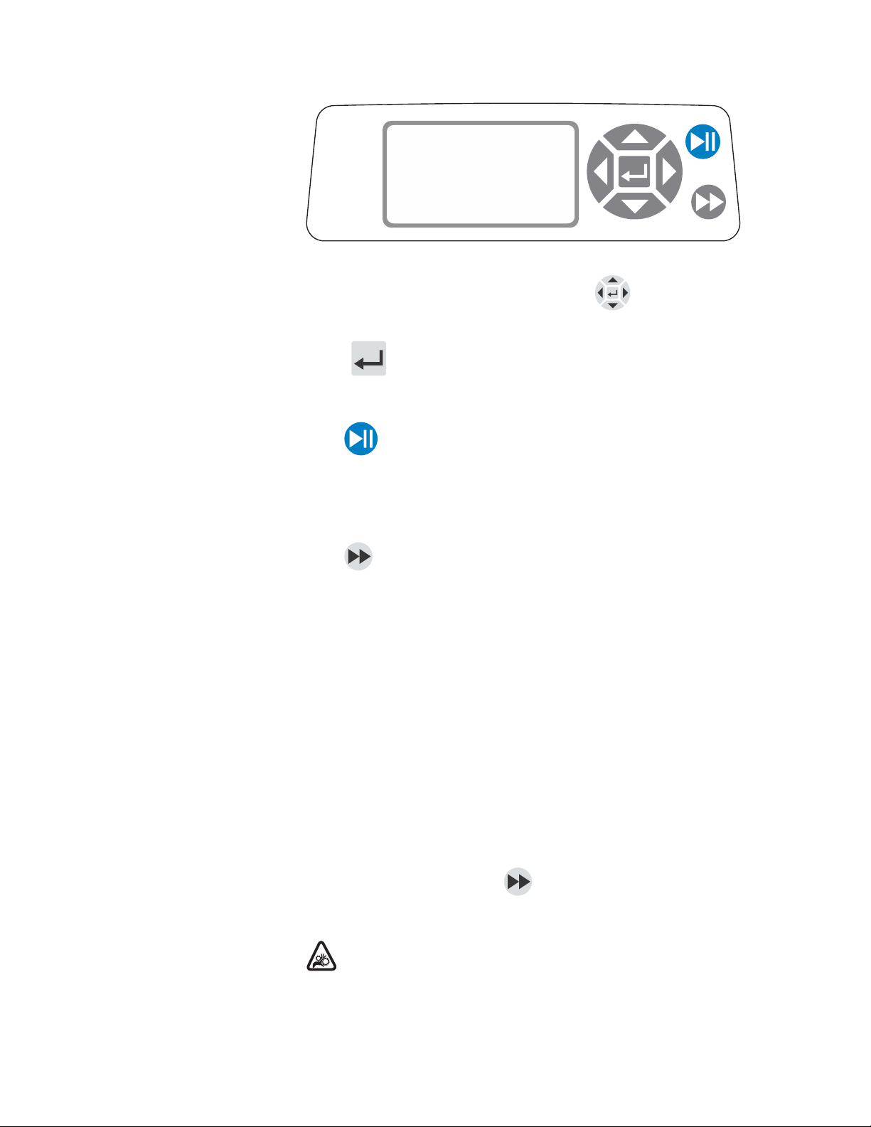
Figure 3-1. Control Panel
• To navigate all menus on the drive use the directional pad
directly to the right of the LCD screen.
• e (ENTER) key located in the middle of the directional pad is used
to enter or select a highlighted field or option. is key is often referred to
as the ENTER key in this manual.
• e (START/STOP) key located at the top right of the control panel is
used to start and pause the drive. is key is functional only when in one of
the four operating modes: Continuous, Time Dispense, Copy Dispense, or
Volume Dispense. is key is often referred to as the START/STOP key in
this manual.
Priming the Pump
• e (PRIME) key located at the bottom right of the control panel issued
to access the prime (fast forward) function. While pressed, this key operates
the drive at the maximum allowed speed/flow rate and in the direction
shown on the display. When released, the drive returns to its original speed
or flow rate.
1. Mount Pump Head to drive.
2. Insert appropriate tubing into Pump Head.
3. Insert tube inlet into supply fluid.
4. Insert supply outlet into desired container.
5. Turn on pump using switch located on the back of the drive.
6. Press and hold the PRIME key on the drive console to prime the
pump. Priming will stop when key is released.
CAUTION: Keep fingers away from rotor while pump is in
operation. Stop pump before loading or unloading tubing.
®
Digital Pump Drive Operating Manual3-2
MasterflexMASTERFLEXLIVE
Page 15

Section 3
Operation
Main Menu
CONTINUOUS MODErefer to Continuous Mode in this manual.
TIME DISPENSE MODErefer to Time Dispense Mode in this manual.
COPY DISPENSE MODErefer to Copy Dispense Mode section in this
manual.
VOLUME DISPENSE MODErefer to Volume Dispense Mode section in
this manual.
REMOTE CONTROL MODErefer to Remote Control Mode section in
this manual.
CUMULATIVE VOLUME:e drive stores and displays the cumulative
volume in units based on flow rate units (see SETUP MENU in this section). e Cumulative Volume can also be reset to zero.
NOTE:e Cumulative Volume is dependent on the Tubing Size selected.
(See SETUP MENUin this section.)
SOUNDS:An audible “beep” can be enabled to indicate a keypad press, the
end of a dispense and/or the end of a batch.
AUTOSTART:By default the drive will not restart when power is applied.
To enable this feature select AUTOSTART and then ON. e drive will
now restart when power is reapplied.
DISPLAY CONTRAST: is display can be adjusted using the
UP/DOWN( / ) arrows after selecting this menu item.
LANGUAGE:After selecting this menu, the user will be able to select one
of seven different languages.
NOTE:If the language is accidentally changed and the user would like to
reset it to the default language (English), press and hold the UP/DOWN
( / ) keys when power is reapplied.
DEFAULT SETTINGS: Selecting this menu item and pressing the
ENTER key will restore default settings. To restore drive to default settings
the user may also press and hold the LEFT/RIGHT ( / ) keys when
power is reapplied.
®
Digital Pump Drive Operating ManualMasterflex
3-3MASTERFLEXLIVE
Page 16

Section 3
Operation
Tubing Calibration 1. Mount Pump Head to drive.
2. Insert appropriate tubing into Pump Head.
3. Insert tube inlet into supply fluid.
4. Insert tube outlet into desired container. Container should be a
graduated container or a container placed on a scale may be used for
increased accuracy.
If using a scale, an acceptable weight to volume conversion for water
is 1 gram = 1 mL.
5. Turn on drive using power switch located on the rear of the drive.
6. Go to the Main Menu or Mode Setup Menu by selecting the SETUP
icon and pressing the ENTER key. Use the UP and DOWN keys
to highlight TUBING CAL in the Main or Setup Menu and press
the ENTER key.
7. Set the drive for the desired flow direction, tube size, and flow rate.
Note that these settings are retained and transferred to other mode
screens when entering or leaving the TUBING CAL screen.
• e flow direction is set using the directional keypad to highlight
the directional arrow. Pressing ENTER will toggle arrow between CW and CCW.
• e tube size is set using the directional keypad to highlight the
tube size field. Press ENTER and use the UP/DOWN keys to
select the tube size. Press ENTER to SAVE the selection and
return to TUBING CAL screen.
• e estimated flow rate is set using the directional keypad to
highlight the flow rate field. Press ENTER and use the
LEFT/RIGHT keys to select the digit to be changed. Use the
UP/DOWN keys to adjust the flow rate value. Press ENTER to
SAVE the setting and EXIT field using arrow keys. e drive will
adjust this flow rate after calibration is complete.
• Note that the calibration volume is fixed and cannot be changed.
8. Press and hold the prime key on the drive console to prime the
pump. Priming will stop when key is released.
9. Place a measuring container at the pump outlet. Highlight the START
field and press the ENTER key. e drive will run based on the
default volume at the estimated flow rate selected.
®
Digital Pump Drive Operating Manual3-4
MasterflexMASTERFLEXLIVE
Page 17

Section 3
Operation
Tubing Calibration
(continued)
10. Upon completion of the calibration run period, the CAL VOLUME
field will be highlighted. Press the ENTER key and adjust the CAL
VOLUME to the measured quantity. Use the LEFT/RIGHT keys to
select digit to be changed, use the UP/DOWN keys to adjust the value,
and press ENTER to SAVE setting and EXIT the field.
A lower case “c” should now be displayed when the calibrated tubing
size is selected. e volume units will depend on the flow rate units. e
flow rate unit mL/min will result in a volume unit of mL; oz/min will
result in a volume unit of oz.
Tubing Calibration Notes
• If the drive is stopped during calibration, empty the container and restart the procedure.
• Calibration time at maximum allowable flow rate (default max flow
rate) is 5-10 seconds and at minimum allowable flow rate (approximately 4% of the maximum flow rate) is 4 minutes. Select the
CUSTOM tube size for other tubing sizes or lower flow rates.
• Minimum and maximum flow rates will change after a tubing calibration due to a re-calculation of the vol/rev.
• Optimum results are best obtained after tubing has been broken in by
running in pump for at least 10 minutes. Steps 8-10 can be repeated
as necessary to optimize the accuracy of the tubing cal.
CAL RUN TIME FORMULA
60 / (flow rate [mL/min] / cal volume [mL]) = cal run time (seconds)
INVALID CAL RUN TIME EXAMPLE
• tube size 13 flow rate range is 0.006 mL/min – 36.0 mL/min
• at flow rate of 1 mL/min, cal run time calculation is as follows:
60 / (1 mL/min / 6 mL) = 360 seconds 360 seconds exceed the max
run time of 4 minutes (240 seconds)
®
Digital Pump Drive Operating ManualMasterflex
3-5MASTERFLEXLIVE
Page 18

Section 3
Operation
Setup Menu
All four operation mode screens contain a SETUP icon in the upper
right hand that gives quick access to the SETUP menu. e exact options
that can be accessed through the SETUP menu will depend on the operating
mode currently in use:
1. Selecting the SETUP Menu:In any of the four operating modes, use the
directional pad and enter key to select the SETUP icon from the mode
operation screen.
2. Navigating the SETUP Menu: Use the directional pad and the
ENTER key to select desired setting.
A breakdown of the setting features common to all modes follows. Other
settings are related to the specific operating mode currently in use and can be
accessed through the mode operation screen as well.
Flow Unit:Select desired flow unit to be displayed.
Tubing Size:Size and Maximum Flow Rate are displayed. Select desired tubing size.
Flow Rate:Set the flow rate in flow unit listed at the top of the screen.
(NOTE:To change flow unit, see Flow Unit above.) When the entire rate field
is highlighted, press ENTER. e digits can be navigated individually using
the UP/DOWN arrows; switch between digits using the LEFT/RIGHT arrows. After selecting an optimal flow rate, press ENTER again to validate.
Tubing Calibration:See Tubing Calibration.
Pump Direction: Select the direction of the pump flow.
Sounds: Select a beep for keypad, end of dispenses, and batches.
Remote Control:See Remote Control.
Keypad Lockout:Allows for the keypad to be locked and unlocked.
Cumulative Volume:View and reset cumulative volume.
Main Menu: Return to the Main Menu.
Exit:Return to the Mode Operation screen.
®
Digital Pump Drive Operating Manual3-6
MasterflexMASTERFLEXLIVE
Page 19

Section 3
Operation
Continuous Mode
Screen
Display Legend: Below is a screenshot of the screen display for the drive in
Continuous Mode. An explanation of the information on the screen follows.
A B
I
G
H
CONTINUOUS MODE
100.00
or
F
mL/min
17
C
D
E
Figure 3-2. Continuous Mode Screen
A. Mode Display: Current operating mode in which the drive will oper-
ate. Pressing ENTER key when highlighted will cycle through the
different operation modes.
B. Setup : Pressing the ENTER key on this icon goes to the Setup
screen. e Setup screen contains most functions that can be accessed
from the Continuous Mode operation screen, including: flow units,
tubing size, flow rate, pump direction, remote control, and keypad
lockout. e Setup screen also provides access to tubing calibration,
sounds, cumulative volume and the Main Menu.
C. Flow Direction:Pressing the ENTER key on this icon toggles between
clockwise and counterclockwise flow direction.
D. Flow Units:Pressing the ENTER key on this icon goes to the Flow Unit
selection screen. NOTE:% and rpm are available in Continuous Mode only.
When switching to Copy Dispense or Volume Dispense Modes % and rpm
units will change to mL/min with values dependent on tubing size selected.
E. Tubing Size:Pressing the ENTER key on this icon goes to the tubing
size selection screen.
F. Current Flow Rate: e center digits show the flow rate of the drive in
the unit of measure selected and shown to the right (see position D, Figure
3-2).
G. Local/Remote or :Pressing the ENTER key on this icon goes to
the Remote Control setup screen. is icon indicates whether your drive
is in local or remote control mode. If the solid rectangle appears in the
center of the figure the drive is set to be operated locally. If the solid
rectangle does not appear in the center of the figure the drive is set to be
operated by remote control.
H. Key Pad Lock :Pressing the ENTER key on this icon goes to the
Keypad Lockout screen. Locking the keypad will prevent someone from
changing the settings on the drive. When locked this icon changes to .
®
Digital Pump Drive Operating ManualMasterflex
3-7MASTERFLEXLIVE
Page 20

Section 3
Operation
Continuous Mode
Operation
CONTINUOUS MODE
100.00
Figure 3-3. Continuous Mode Operation
1. Getting Started:From the Main Menu, use the ENTER key to select
Continuous Mode to enter the Continuous Mode Operation screen.
2. Calibrating Tubing:Before operating the pump, insert desired tubing into
the Pump Head. For more information, see “Tubing Calibration”.
3. Preparing External Supplies:Insert tube inlet into supply fluid. Next,
insert tube outlet into desired container.
4. Starting the Drive:From this operation screen, simply pressing the
START/STOP key will start the drive at the speed/flow rate and direction shown. In Continuous Mode the drive will operate at the displayed speed/flow rate and direction continuously.
mL/min
17
5. Stopping the Drive:To pause or stop the drive, press the START/
STOP key in the top right hand corner of the console.
6. Changing Speed/Flow Rate:To change the speed/flow rate of the drive,
use the directional pad to highlight the numeric field in the center of
the display and press the ENTER key. is puts you in a position to
change the speed/flow rate of the drive at the farthest digit to the right
(tenths, hundredths, thousandths, etc depending on flow unit). Pressing
the UP arrow on the directional pad will increase the speed/flow rate by
one value and pressing the DOWN arrow will decrease the speed/flow
rate by one value. Pressing the ENTER key again will show all the possible digits that can be manipulated for the specific flow unit currently
in use; use the LEFT/RIGHT arrows on the directional pad to move
between digits and the UP/DOWN arrows to increase or decrease the
value, respectively. Once desired speed/flow rate is selected, press ENTER key a final time to set the drive to operate at that speed/flow rate.
7. Changing Flow Unit:To change the flow unit of the drive pause the drive
using the START/STOP key. Next, use the directional pad to select the
Flow Units icon and press the ENTER key. Use the UP/DOWN arrow
on the directional pad to select the desired flow unit and press the ENTER key to choose that unit. e drive will now operate in that flow
unit. Press the START/STOP key to resume operating the drive.
®
Digital Pump Drive Operating Manual3-8
MasterflexMASTERFLEXLIVE
Page 21

Section 3
Operation
Time Dispense Mode
Screen
Display Legend:Below is a screenshot of the screen display for the drive in
Time Dispense Mode. An explanation of the information on the screen fol-
lows.
I
G
H
A
TIME DISP. MODE
B
00:00:00
1000/2000
or
F
C
D
ON
E
OFF
Figure 3-4. Time Dispense Mode Screen
A. Mode Display: Current operating mode.
B. Setup: e Setup screen can be used to select flow units, tubing size,
flow rate, tubing calibration, sounds, cumulative volume, and Main
Menu. e Setup screen contains some functions that can be accessed
from the Time Dispense Mode operation screen, including: pump direction, on/off time, batch count, remote control, and keypad lockout.
C. Flow Direction:Pressing the ENTER key on this icon toggles between
clockwise and counterclockwise flow direction.
D. Pump ON Time:When this field is highlighted the drive is ON.
NOTE: e drive will not show 00:00 when switching from ON to
OF time.
E. Pump OFF Time: When this field is highlighted the drive is OFF.
F. Batch Count: Displays the number of cycles dispensed in the batch.
G. Local/Remote or : Pressing the ENTER key on this icon goes to the
Remote Control setup screen. is icon indicates whether your drive
is in Local or Remote Control mode. If the solid rectangle appears in
the center of the figure the drive is set to be operated locally. If the solid
rectangle does not appear in the center of the figure the drive is set to be
operated by remote control.
H. Key Pad Lock : Pressing the ENTER key on this icon goes to the
Keypad Lockout screen. Locking the keypad will prevent someone from
changing the settings on the drive. When locked this icon changes to .
I. Time Display: e center digits show the remaining time of the drive
in the ON or OFF Time highlighted on the right of the display
(position D or E, Figure 3-4).
®
Digital Pump Drive Operating ManualMasterflex
3-9MASTERFLEXLIVE
Page 22

Section 3
Operation
Time Dispense
Mode Operation
TIME DISP. MODE
00:00:00
ON
1000/2000
Figure 3-5. Time Dispense Mode Operation
1. Getting Started:From the Main Menu, use the enter key to select Time
Dispense Mode to enter the Time Dispense Mode Operation screen.
2. Calibrating Tubing: Before operating the pump, insert desired tubing
into the Pump Head. For more information, see “Tubing Calibration”.
3. Choosing Settings:Select desired flow unit, tube size, flow rate, pump
direction, etc. For more information see “SETUP Menu.”
4. Preparing Tubing: Insert tube inlet into supply fluid. Next, insert tube
outlet into desired container.
5. Selecting Flow Rate:Use the directional pad and ENTER key to select
the Setup icon. Use the UP/DOWN arrows on the directional pad to
select Flow Rate. In the Flow Rate selection screen, press the ENTER
key and then use the UP/DOWN arrows on the directional pad to select a desired flow rate. For faster entry, use the LEFT/RIGHT arrows
on the directional pad to move between digits and the UP/DOWN
arrows to increase or decrease the value, respectively. Press ENTER one
more time to validate the selected flow rate. Use the directional pad to
select EXIT to return to the Time Dispense Mode Setup Screen.
OFF
6. Setting ON Time:To set the ON Time, use the directional pad and
ENTER key to select the ON field (see position D, Figure 3-4). Doing
so will highlight the timer in the center of the screen (see position I,
Figure 3-4). Pressing ENTER again, allows the timer to be set using the
UP/DOWN arrows. Switch between digits using the LEFT/RIGHT
arrows. Having selected an optimal ON Time, press ENTER again to
validate. e drive will now run for the time appearing in the center of
the screen.
®
Digital Pump Drive Operating Manual3-10
MasterflexMASTERFLEXLIVE
Page 23

Section 3
Operation
Time Dispense Mode
Operation (continued)
7. Setting OFF Time:To set the OFF Time, use the directional pad and
ENTER key to select the OFF field (see position E, Figure 3-4). Doing so will highlight the timer in the center of the screen (see position
I, Figure 3-4). Pressing ENTER again, allows the timer to be set using
the UP/DOWN arrows. Switch between digits using the LEFT/RIGHT
arrows. Having selected an optimal OFF Time, press ENTER again
to validate. e drive will stop running for the time appearing in the
center of the screen. NOTE: If the OFF Time is set to 00:00:00, the drive
requires a START/STOP input from the keypad or the remote I/O
Connector to start the next dispense.
8. Selecting Batch Size:Before running the drive at the selected ON/ OFF
Times, select a batch size for the operation. To do so, use the directional
pad and the ENTER key to select the BATCH icon (see position F,
Figure 3-4). In the Batch Count screen, press the ENTER key and then
use the UP/DOWN arrows on the directional pad to select a batch size.
Switch between digits using the LEFT/RIGHT arrows. Press ENTER
one more time to validate the selected batch size. When set to zero (0)
the drive will run for an infinite number of cycles and the symbol is
displayed. Use the directional pad to select EXIT to return to the Time
Dispense Operation Screen.
9. Starting the Drive:e drive is now set to operate, press the START/
STOP key in the upper right hand corner to start the drive. e drive
can be paused at any time throughout the batch to adjust flow direction, tubing size, flow units, flow rate, etc.
10. Resetting Batch:To reset a batch, use the directional pad and the ENTER key to select the BATCH icon (see position F, Figure 3-4). In the
Batch Count screen, use directional pad to select RESET and press the
ENTER key to reset the batch count, select EXIT to return to the main
Time Dispense Mode operation screen.
®
Digital Pump Drive Operating ManualMasterflex
3-11MASTERFLEXLIVE
Page 24

Section 3
Operation
Copy Dispense Mode
Screen
Display Legend:Below is a screenshot of the screen display for the drive in
Copy Dispense Mode. An explanation of the information on the screen
follows.
A
COPY DISP. MODE
J
100.00
I
or
H
G
53 %
1000/2000
F
B
COPY
C
K
D
E
OFF
Figure 3-6. Copy Dispense Mode Screen
A. Mode Display:Current operating mode.
B. Setup : e Setup screen can be used to select flow units, tubing size,
flow rate, tubing calibration, sounds, cumulative volume, and Main
Menu. e Setup screen contains some functions that can be accessed
from the Time Dispense Mode operation screen, including:
pump direction, on/off time, batch count, remote control, and keypad
lockout.
C. Flow Direction:Pressing the ENTER key on this icon toggles between
clockwise and counterclockwise flow direction.
D. Copy Amount Screen: See Copy Setting Screen, Figure 3-8.
E. Pump OFF Time:Highlighted when the drive is OFF.
F. Batch Count: Displays the number of cycles dispensed in the batch.
G. Local/Remote or :Pressing the ENTER key on this icon goes to the
Remote Control setup screen. is icon indicates whether your drive is in
local or remote control mode. If the solid rectangle appears in the center
of the figure the drive is set to be operated locally. If the solid rectangle
does not appear in the center of the figure the drive is set to be operated
by remote control.
H. Keypad Lock : Pressing the ENTER key on this icon goes to the
Keypad Lockout screen. Locking the keypad will prevent someone
from changing the settings on the drive. When locked this icon
changes to .
I. Percentage Completed: is icon displays the portion of fluid
dispensed as a percentage.
J. Copy Volume:Displays the Copy Volume while dispensing or the
OFF Time.
K. Anti-Drip:A waterdrop icon present indicates that the Anti-Drip function
is on. For further information see Anti-Drip Function page 3-27.
®
Digital Pump Drive Operating Manual3-12
MasterflexMASTERFLEXLIVE
Page 25

Section 3
Operation
Copy Dispense Mode
Operation
COPY DISP. MODE
100.00
53 %
1000/2000
Figure 3-7. Copy Dispense Mode Operation
1. Getting Started: From the Main Menu, use the ENTER key to select
Copy Dispense Mode to enter the Copy Dispense Mode operation
screen.
2. Calibrating Tubing: Before operating the pump, insert desired tubing
into the Pump Head. For more information, see “Tubing Calibration”.
3. Choosing Settings: Select desired flow unit, tube size, flow rate, pump
direction, etc. For more information see “Using the SETUP Menu.”
4. Preparing Tubing: Insert tube inlet into supply fluid. Next, insert tube
outlet into desired container.
COPY
OFF
5. Setting Copy Amount: See Copy Setting Operation.
6. Setting OFF Time: Use the directional pad and ENTER key to select
OFF on the display to enter the Pump OFF Time. Use the directional
pad and ENTER key to set the Pump OFF Time. e timer in the
center of the screen will be highlighted, and using the UP/DOWN arrows will increase/decrease the farthest right digit of the time interval.
Switch between digits using the LEFT/RIGHT arrows. After selecting
an optimal OFF Time, press ENTER again to validate. e drive will
now rest for the time appearing in the center of the screen.
NOTE:If the OFF Time is set to 00:00:00, the drive requires a START/
STOP input from the keypad or the remote I/O Connector to start
the next dispense.
7. Setting Batch Size: Use the directional pad and ENTER key to select
the Batch Count icon from the operation screen (see position F, Figure
3-6). From Batch Count screen use the UP/DOWN arrows to select
batch size. Press ENTER to validate batch size. When set to zero (0)
the drive will run for an infinite number of cycles and the symbol is
displayed. Select EXIT to return to the Copy Dispense Mode screen.
• Batch count may be reset from BATCH COUNT screen by
selecting RESET.
®
Digital Pump Drive Operating ManualMasterflex
3-13MASTERFLEXLIVE
Page 26

Section 3
Operation
Copy Dispense Mode
Operation (continued)
8. Operating Drive: Press the START/STOP key to operate the drive at the
settings selected and displayed on the screen. Press again to pause or stop
the drive. Drive will automatically stop once batch is complete.
9. Reset Batch Count: Use the directional pad and the ENTER key to select
the BATCH COUNT icon (see position F, Figure 3-6). In the BATCH
COUNT screen, select RESET and press the ENTER key to reset the
batch count. Select EXIT to return to the Copy Mode Operation screen.
10. Maximum Dispense Time: e specification for the maximum dispense
in Copy Mode is over 80+ hours at 600 rpm for L/S drives or 77 hours @
650 rpm for I/P drives. Actual maximum volume is dependant on tubing
size and flow units selected.
®
Digital Pump Drive Operating Manual3-14
MasterflexMASTERFLEXLIVE
Page 27

Section 3
Operation
COPY Setting Screen
Display Legend: Below is a screenshot of the screen display for the drive in
Copy Setting Mode. An explanation of the information on the screen follows.
A
COPY
H
10000
EXIT
G F
CLEAR
B
START
C
D
mL/min
E
STOP
Figure 3-8. COPY Setting Screen
A. Mode Display: Current operating mode.
B. START: is icon will start drive allowing for copy volume to be set.
C. Flow Direction: Pressing the ENTER key on this icon toggles between
clockwise and counterclockwise flow direction.
D. Volume Unit: is is dependent on the flow rate selected.
E. STOP: is stops the Copy and sets the volume to be dispensed. It is
displayed in position H.
F. CLEAR: Selecting this will clear the number displayed on the screen
and will allow for a new copy volume to be selected.
G. EXIT: Return to Copy Dispense Mode.
H. Volume: is is the amount that was dispensed during the copy.
®
Digital Pump Drive Operating ManualMasterflex
3-15MASTERFLEXLIVE
Page 28

Section 3
Operation
COPY Setting
Operation
COPY
10000
EXIT
Figure 3-9. COPY Setting Operation
1. Getting Started: From the COPY DISPENSE MODE Screen select
COPY and ENTER.
2. Clear Volume:Using the directional Keypad select CLEAR and ENTER.
3. Establish Copy Volume:3 methods are available to the user.
a. Place the desired container at the tubing outlet. Press the START/
STOP keyto initiate the dispensing of fluid. When you have
reached the desired volume press the START/STOP keyagain.
Select EXIT and press ENTER. e drive will store the value of
the copy in memory and use that value in the COPY DISPENSE
MODE.
CLEAR
START
mL/min
STOP
b. Place the desired container at the tubing outlet. Select the START
field on the screen and press the ENTER key to initiate the dispensing of fluid. e drive will now highlight the STOP field on
the screen. When you have reached the desired volume press the
ENTER key to stop. Select EXIT and press ENTER. e drive
will store the value of the copy in memory and use that value in the
COPY DISPENSE MODE.
c. Place the desired container at the tubing outlet. Close the contacts
on the START/STOP input to initiate the dispensing of fluid.
When you have reached the desired volume, close and release the
contacts on the START/STOP input. Select EXIT and press ENTER. e drive will store the value of the copy in memory and use
that value in the COPY DISPENSE MODE.
NOTE: e value displayed as the volume in the COPY SETTING screen
and the COPY DISPENSE Mode screen depend on the flow units selected. RPM, and % are invalid. If these units have been selected the drive will
display a volume in mL, in the COPY DISPENSE MODE, that is dependent on the tubing size selected.
See TUBING CALIBRATION to improve the accuracy of this conversion.
®
Digital Pump Drive Operating Manual3-16
MasterflexMASTERFLEXLIVE
Page 29

Section 3
Operation
Volume Dispense
Mode Screen
Display Legend: Below is a screen shot of the screen display for the drive in
Volume Dispense Mode. An explanation of the information on the screen
follows.
A
VOL DISP. MODE
I
G
100.00
H
1000/2000
or
B
C
J
D
mL
E
OFF
F
Figure 3-10. Volume Dispense Mode Screen
A. Mode Display: Current operating mode.
B. Setup : e Setup screen can be used to select flow units, tubing size,
flow rate, tubing calibration, sounds, cumulative volume, and Main
Menu. e Setup screen contains some functions that can be accessed
from the Time Dispense Mode operation screen, including: pump direction, on/off time, batch count, remote control, and keypad lockout.
C. Flow Direction: Pressing the ENTER key on this icon toggles between
clockwise and counterclockwise flow direction.
D. Flow Units: Select desired flow unit.
E. Pump OFF Time: Highlighted when the drive is OFF.
F. Batch Count: Displays the number of cycles dispensed in the batch.
G. Local/Remote or : Pressing the ENTER key on this icon goes to
the Remote Control setup screen. is icon tells you whether your
drive is in local or remote control mode. If the solid rectangle appears
in the center of the figure the drive is set to be operated locally. If the
solid rectangle does not appear in the center of the figure the drive is
set to be operated by remote control.
H. Keypad Lock: Pressing the ENTER key on this icon goes to the Key-
pad Lockout screen. Locking the keypad will prevent someone from
changing the settings on the drive. When locked this icon changes to .
I. Volume: Displays the Volume while dispensing or the OFF Time.
J. Anti-Drip: A water drop icon present indicates that the Anti-Drip
function is on. For further information see Anti-Drip Function page
3-27.
®
Digital Pump Drive Operating ManualMasterflex
3-17MASTERFLEXLIVE
Page 30

Section 3
Operation
Volume Dispense
Mode Operation
VOL DISP. MODE
100.00
1000/2000
Figure 3-11. Volume Dispense Mode Operation
1. Getting Started: From the Main Menu, use the ENTER key to select
Volume Dispense Mode to enter the Volume Dispense Mode operation
screen.
2. Calibrating Tubing: Before operating the pump, insert desired tubing
into the Pump Head. For more information, see “Tubing Calibration”.
3. Choosing Settings: Select desired flow unit, tube size, flow rate, pump
direction, etc. For more information see “SETUP Menu.”
4. Preparing Tubing: Insert tube inlet into supply fluid. Next, insert tube
outlet into desired container.
mL
OFF
5. Setting Desired Volume: Using the directional pad highlight the numeric field in the center of the display and press the ENTER key. is puts
you in a position to change the fluid volume of the drive at the farthest
digit to the right (tenths, hundredths, thousandths, etc., depending on
your volume unit). Pressing the UP arrow on the directional pad will
increase the volume by one value and pressing the DOWN arrow will
decrease the volume by one value. Pressing the ENTER key again will
show all the possible digits that can be manipulated for the specific
volume unit currently in use; use the LEFT/RIGHT arrows on the
directional pad to move between digits and the UP/DOWN arrows
to increase or decrease the value, respectively. Once desired volume is
selected, press ENTER a final time to set the drive to operate at that
volume. Press the START/STOP key to resume operating the drive.
6. Setting Pump OFF Time: Use the directional pad and ENTER key to
select OFF on the display (see position E, Figure 3-10) to enter the
OFF TIME. Use the directional pad and ENTER key to set the pump
rest time. e timer in the center of the screen will be highlighted, and
using the UP/DOWN arrows will increase/decrease the farthest right
digit of the time interval. If ENTER is pressed a second time while the
timer is highlighted, the digits can be navigated individually using the
UP/DOWN arrows; switch between digits using the LEFT/RIGHT
arrows. After selecting an optimal OFF time, press ENTER again to
validate. e drive will now rest for the time appearing in the center of
the screen. NOTE:If the OFF Time is set to 00:00:00, the drive requires
a START/STOP input from the keypad or the remote I/O Connector
to start the next dispense.
®
Digital Pump Drive Operating Manual3-18
MasterflexMASTERFLEXLIVE
Page 31

Section 3
Operation
Volume Dispense
Mode Operation
(continued)
7. Setting Batch Size: Use the directional pad and ENTER key to select
the Batch Count icon from the operation screen (see position F, Figure
3-10). From Batch Count screen use the UP/DOWN arrows to select
batch size. Press ENTER to validate batch size. When set to zero (0)
the drive will run for an infinite number of cycles and the ∞ symbol is
displayed. Select EXIT to return to drive operation screen.
• Batch count may be reset from the Batch Count screen by selecting
RESET.
8. Operating the Drive: Press the START/STOP key to operate the drive
continuously at the settings selected and displayed on the screen. Press
again to pause or stop the drive. Drive will automatically stop once
batch is complete.
9. Reset Batch Count: Use the directional pad and the ENTER key to
select the BATCH COUNT icon (see position F, Figure 3-10). In the
BATCH COUNT screen, select RESET and press the ENTER key
to reset the batch count. Select EXIT to return to the COPY MODE
OPERATION screen.
10. Maximum Dispense Time: e specification for the maximum dispense
volume in Volume Mode is over 80+ hours at 600 rpm for L/S drives or
77 hours @ 650 rpm for I/P drives. Actual maximum volume is dependant on tubing size and flow units selected.
®
Digital Pump Drive Operating ManualMasterflex
3-19MASTERFLEXLIVE
Page 32

Section 3
Operation
Remote Control Menu
REMOTE CONTROL
LOCAL
CURRENT INPUT
CURRENT OUTPUT
VOLTAGE INPUT
VOLTAGE OUTPUT
START/STOP
EXIT
Figure 3-12. Remote Control Menu Screen
NAVIGATION: From the Main Menu or SETUP Menu select REMOTE
CONTROL and ENTER.
LOCAL: When this is selected the drive is controlled by the front panel
keypad, Start/Stop Input, Directional Input or Prime Input.
CURRENT INPUT: When this is selected, the drive is in remote control.
is allows the user to input a current signal to control the flow. e user
has an option to adjust the minimum, maximum and middle set points
for current and flow. By default the minimum (MIN) current is set to 4.2
mA and the flow is set to 0. e maximum (MAX) is set to 20 mA and the
flow is set to maximum. e middle (MID) is auto calculated for a current and flow that is centered between the MIN and the MAX. e MID
can be adjusted if other profiles are needed. e scaling can be inverted if
necessary. To confirm CURRENT INPUT MODE is selected, select EXIT
after returning to the Remote Control Menu, then select CONTINUOUS
PUMP MODE. To deselect Remote Current Input Mode select LOCAL
and ENTER.
NOTE: When Current Input is selected the drive will not start until the
REMOTE CONTROL MODE is exited and CONTINUOUS PUMP
MODE is selected.
CURRENT OUTPUT: is allows the user to adjust the current output
for a given flow. e user has an option to adjust the minimum, maximum
and middle setpoints for current and flow. By default the minimum (MIN)
flow is set to 0.00 and the current is set to 4.0 mA. e maximum (MAX)
is set to maximum flow and the current is set to 20.0 mA. e middle
(MID) is auto calculated for a current and flow that is centered between the
MIN and the MAX. e MID can be adjusted if other profiles are needed.
is allows for a three-point calibration of the current output. e flow is
linear between these points. e scaling can be inverted if necessary. NOTE:
Selecting Current Output will not put user into REMOTE CONTROL
MODE. Only selecting VOLTAGE INPUT or CURRENT INPUT will
put the user into Remote Control Mode, as indicated by the empty house
icon (see position G, Figure 3-2). NOTE:e Current Output indicates the
Running Command Speed. Use the Motor Running contacts (normally
open/closed) to indicate if pump is running.
®
Digital Pump Drive Operating Manual3-20
MasterflexMASTERFLEXLIVE
Page 33

Section 3
Operation
Remote Control Menu
(continued)
VOLTAGE INPUT: When this is selected, the drive is in remote control.
is allows the user to input a voltage signal to control the flow. e user
has an option to adjust the minimum, maximum and middle set points for
voltage and flow. By default the minimum (MIN) voltage is set to 00.1
V DC and the flow is set to 00.0. e maximum (MAX) is set to 10.0 V
DC and the flow is set to maximum. e middle (MID) is auto-calculated
for a voltage and flow that is centered between the MIN and the MAX.
e MID can be adjusted if other profiles are needed. e scaling can be
inverted, if necessary. To confirm VOLTAGE INPUT MODE is selected,
select EXIT after returning to the Remote Control Menu, then select CONTINUOUS PUMP MODE. To deselect Remote Voltage Input Mode select
Local and ENTER.
NOTE: When Voltage Input is selected the drive will not start until the
REMOTE CONTROL MODE is exited and CONTINUOUS PUMP
MODE is selected.
VOLTAGE OUTPUT: is allows the user to adjust the voltage output for
a given flow. e user has an option to adjust the minimum, maximum and
middle set points for voltage and flow. By default the minimum (MIN)
flow is set to 00.00 and the voltage is set to 00.0V DC. e maximum
(MAX) is set to maximum flow and the voltage is set to 10.0V DC. e
middle (MID) is auto calculated for a voltage and flow that is centered between the MIN and the MAX. e MID can be adjusted if other profiles are
needed. is allows for a three point calibration of the voltage output. e
flow is linear between these points. e scaling can be inverted if necessary.
NOTE: Selecting Voltage Output will not put the user into Remote Control
Mode. Only selecting Voltage Input or Current Input will put the user into
Remote Control Mode, as indicated by the empty house icon (see position
G, Figure 3-2). NOTE: e Voltage Output indicates the Running Command Speed. Use the Motor Running contacts (normally open/closed) to
indicate if pump is running.
START/STOP: e START/STOP input can be configured to be OFF
(factory default), or ON for the drive to run.
With the OFF selected (factory default), use of the START/STOP input
is optional. When the START/STOP input is open, the drive can still be
started using the START/STOP key, PRIME key, or PRIME input. In
remote modes the drive will also run if there is sufficient current or voltage
at the input.
Closing the START/STOP input will cause the drive to run until the
START/STOP input opens or the START/STOP key is pressed. In Time
dispense, Copy dispense, and Volume dispense mode, only a momentary
START/STOP closure is needed to start the drive. If the drive is already
running in one of the dispense modes, a momentary START/STOP closure
will stop the drive. In SET COPY MODE, the START/STOP input functions the same as in CONTINUOUS MODE; closing it will cause the drive
to run until it opens.
®
Digital Pump Drive Operating ManualMasterflex
3-21MASTERFLEXLIVE
Page 34

Section 3
Operation
Remote Control Menu
(continued)
e function of the START/STOP input is considerably simplified when
the ON is selected. e drive will not run under any condition unless the
START/STOP input is closed.
Table 3-1. Continuous Mode Operation
MENU SETTINGS
SETUP OPTIONS
AUTO
START/STOP
START
REQUIRED
OFF OFF OPEN Running Not running Not running
OFF OFF OPEN Not running Not running Not running
OFF OFF CLOSED Forced run due to
OFF ON OPEN Forced not running
OFF ON CLOSED Forced run due to
ON OFF OPEN Running Running Running
ON OFF OPEN Not running Not running Running
ON OFF CLOSED Forced run due to
ON ON OPEN Forced not running
ON ON CLOSED Forced run due to
NOTE: In Continuous Mode when using the START/STOP input the drive is started with a closed contact and
stopped when the contacts are opened.
START/STOP
INPUT
Drive State When
Powered OFF
S/S CLOSED
due to S/S OPEN
S/S CLOSED
S/S CLOSED
due to S/S OPEN
S/S CLOSED
INTERNAL MODE mA or V MODE
Drive Response When
Powered ON
Not running Not running
Not running Not running
Not running Not running
Running Running
Not running Not running
Running Running
Drive Running
(sufficient level)
When Powered OFF
Drive Response when
Powered ON
(sufficient level present)
Table 3-2. Dispense Mode Operation
MENU SETTING SETUP OPTIONS START/STOP
AUTO START START/STOP
REQUIRED
OFF OFF OPEN Running Not running
OFF OFF OPEN Not running Not running
OFF OFF CLOSED* Forced run due to S/S
OFF ON OPEN Forced not running due
OFF ON CLOSED Forced run due to S/S
ON OFF OPEN Running Running
ON OFF OPEN Not running Not running
ON OFF CLOSED* Forced run due to S/S
ON ON OPEN Forced not running due
ON ON CLOSED Forced run due to S/S
* NOTE: In Dispense Modes and START/STOP MENU SETUP Option OFF the drive will start a dispense with
a momentary contact closure and stop with a momentary contact closure during both the dispense period
and interval period.
INPUT
Drive State When
Powered OFF
CLOSED
to S/S OPEN
CLOSED
CLOSED
to S/S OPEN
CLOSED
Drive Response When
Powered ON
Not running
Not running
Not running
Running
Not running
Running
®
Digital Pump Drive Operating Manual3-22
MasterflexMASTERFLEXLIVE
Page 35

Section 3
Operation
DB-25 Pin
Configuration with
Wiring Scheme
Contact Arrangements
M
13 1 12 11 10 9 8 7 6 5 4 3 2
25 24 23 22 21 20 19 18 17 16 15 14
K
A. START/STOP
B. CW/CCW
C. OUTPUT 0-20mA; 4-20mA
D. INPUT 0-20mA; 4-20mA
E. INPUT 0-10V
F. OUTPUT 0-10V
G. TACH OUTPUT
L
H. PRIME
I. MOTOR RUNNING N.O. (1A @ 24 V)
J. MOTOR RUNNING N.C. (1A @ 24 V)
K. 24V (150mA max.)
L. General Alarm
M. Local/Remote Indicator
I
J
G
H
Figure 3-13. DB-25 Pin Configuration with Wiring Scheme
Pin No. Description
DB-25
1 Speed Control Voltage Input (0-10 V)
2 Speed Control Current Input (0-20 mA)
3 Speed Control Input Ground Return
4 Speed Signal Current Output (0-20 mA)
5 Speed Signal Output Ground Reference
6 (Motor Running N.O. Default) 1A @24 V (Open Collector)
7 Motor Running Ground Return
8 (Motor Running N.C. Default) 1A @24 V (Open Collector)
14 Speed Signal Voltage Output (0-10 V)
15 Remote Start/Stop Input
16 Remote CW/CCW Input
17 Remote Start/Stop, CW/CCW, Prime Grnd Ref.
18 Tach Ground Reference
19 Tach Output (open collector)
20 Remote Prime Input
9 Reserved – Not Used
10 Reserved – Not Used
11 Auxiliary Input (Computer Compatible Drive Only)
12 Auxiliary Input Return (Computer Compatible Drive Only)
21 Auxiliary Output #1 (Computer Compatible Drive Only)
22 Auxiliary Output #2 (Computer Compatible Drive Only)
23 General Alarm (Open Collector)
24 Local.Remote Indicator (Open Collector)
25 Aux 24V+ (150 mA)
13 Aux 24V- (150 mA)
F
C
D
B
A
E
NOTE: Pins 5, 13, 17, and 18 are at earth ground, all are suitable for use
with START/STOP, PRIME, Direction, Tach, LOCAL/REMOTE, General Alarm Signals and Current and Voltage Outputs.
CAUTION: Power must be turned off before connecting the
!
external remote control cable to prevent damage to the drive.
NOTE: Open collector outputs in “low impedance” state are at earth ground
and when in “high impedance” state are essentially floating. See Open Collector page following.
®
Digital Pump Drive Operating ManualMasterflex
3-23MASTERFLEXLIVE
Page 36

Section 3
Operation
31-Pin
Configuration with
Wiring Scheme
Contact Arrangements
14
18
31- #20
13
8
3
1
2
7
19
25
30
31
29
24
Figure 3-14. 31-Pin Configuration with Wiring Scheme
Pin No. Description
1 Speed Control Voltage Input (0-10 V)
2 Speed Signal Voltage Output (0-10 V)
3 Speed Control Current Input (0-20 mA)
4 Remote Start/Stop Input
5 Speed Control Input Ground Return
6 Remote CW/CCW Input
7 Speed Signal Current Output (0-20 mA)
8 Remote Start/Stop, CW/CCW, Prime Grnd Ref.
9 Speed Signal Output Ground Reference
10 Tach Ground Reference
11 (Motor Running N.O. Default) 1A @24 V (Open Collector)
12 Tach Output (open collector)
13 Motor Running Ground Return
14 Remote Prime Input
15 (Motor Running N.C. Default) 1A @24 V (Open Collector)
16 Reserved – Not Used
17 Reserved – Not Used
18 Reserved – Not Used
19 Reserved – Not Used
20 General Alarm (Open Collector)
21 Reserved – Not Used
22 Local.Remote Indicator (Open Collector)
23 Reserved – Not Used
24 Aux 24V+ (150 mA)
25 Aux 24V- (150 mA)
26 Reserved – Not Used
27 Reserved – Not Used
28 Reserved – Not Used
29 Reserved – Not Used
30 Reserved – Not Used
31 Reserved – Not Used
NOTE: Pins 8, 9, 10, and 25 are at earth ground, all are suitable for use
with START/STOP, PRIME, Direction, Tach, LOCAL/REMOTE, General Alarm Signals and Current and Voltage Outputs.
CAUTION: Power must be turned off before connecting the
!
external remote control cable to prevent damage to the drive.
NOTE: Open collector outputs in “low impedance” state are at earth
ground and when in “high impedance” state are essentially floating. See
Open Collector page following.
®
Digital Pump Drive Operating Manual3-24
MasterflexMASTERFLEXLIVE
Page 37

Section 3
Operation
Remote Control Inputs
and Outputs
INPUTS
Remote CW/CCW, Remote Start/Stop, Remote Prime, & Aux. In:
e remote control inputs work with current sinking outputs (open-collector NPN transistor outputs without passive pull-up resistors) or contact
closures to DC common (earth ground). A continuous active low to the
Remote Start/Stop inputcauses the drive to run, while a continuous active
low to the Remote CW/CCW input causes the drive to run CCW. e
motor is brought to a controlled stop before reversing direction. A continuous active low to the Remote Prime input causes the drive to run at full
rated speed.
Table 3-3. Remote Control Inputs and Outputs
CURRENT CLOSED INPUT 1 mA TYP
VOLTAGE OPEN INPUT 3.2 V TYP
THRESHOLD CURRENT TO ACTIVATE 0.5 mA TYP
Remote Analog Input:
4-20 mA Input: 250 ohms typical input impedance ref. to signal
ground. 4 mA, Stop; 20 mA, Full Speed (Default Settings) 10 Bit Resolution
Overload Capability: 10 V or 40 mA max.
0-10 V Input: 10 K ohms typical input impedance ref. to signal
ground. 0 V, Stop; 10 V, Full Speed (Default Settings) 10 Bit Resolution
OUTPUTS
4-20 mA Output: 0 to 600 ohms max. load referenced to earth
ground.
4 mA, Stop; 20 mA, Full Speed (Default Settings) 10 Bit Resolution
0-10 V Output: 1.0 K ohms min. load referenced to earth ground.
0 V, Stop; 10 V, Full Speed (Default Settings) 10
Bit Resolution
Tach Output: Open Collector, 1.0A @ 28V DC
Frequency range: L/S: 100 to 6000 Hz or 100 to 1000 Hz,
50% Duty Cycle. (10 Hz = 1 pump rpm)
I/P: 100 to 6500 Hz,
50% Duty Cycle. (10 Hz = 1 pump rpm)
Logic Outputs: Open Collector, 1.0 A @ 28V DC
Motor Running Outputs: Normally Open and Normally Closed when drive
is running.
General Alarm Output: Open (High Impedance) when an alarm is displayed.
Local/Remote Indicator: Open (High Impedance) when in remote
control mode (Voltage Input or Current Input).
®
Digital Pump Drive Operating ManualMasterflex
3-25MASTERFLEXLIVE
Page 38

Section 3
Operation
Open Collector
Outputs
Some remote outputs on this drive (Tachometer, Local/Remote, Motor Running and Alarm) are “open collector” type outputs and cannot be wired in
the same manner as relay outputs. An open collector output is not isolated
and must be configured differently than a relay output.When the open collector output is active, the output is effectively switched to earth ground and
if improperly terminated could result in damage to the drive and/or external
equipment.
Recommendation
When connecting to open collector outputs, the output should be connected
to a current limiting resistor and then to a positive supply source which is less
than 28V DC. Typically this would be connected to a 24V PLC input (see
Figure 3-15).
NOTE: when using the 24V supply on the interface connector, current
draw must be limited to 150 mA.
NOTE: DO NOT connect 120V supply lines to open collector outputs!
+24V
10k
Output
To PLC
Figure 3-15. Terminating Open Collector Outputs to a PLC
®
Digital Pump Drive Operating Manual3-26
MasterflexMASTERFLEXLIVE
Page 39

Section 3
Operation
Anti-Drip Function
e same drive offers an Anti-Drip feature. e tendency of fluid to drip
after a dispense is dependant on several factors including tubing size, tubing
orientation, and the viscosity of the fluid. To minimize this drip the drive
will reverse direction after a dispense to draw the fluid back at the end of the
tubing.
To access this feature select in either Copy Dispense Mode or Volume
Dispense Mode ANTI-DRIP.
ANTI-DRIP
ON
OFF
EXIT
Figure 3-16. Anti-Drip Screen
If the ANTI-DRIP function is desired, select ON and a second screen will
appear which will allow the user to input how many degrees of reverse
rotation the drive will perform. Typical values range from 5 to 45 degrees.
To exit without changing the current setup select EXIT.
ANTI-DRIP
45
EXIT
Figure 3-17. Anti-Drip Degrees Screen
With the number highlighted press the ENTER key and use the UP and
DOWN, and RIGHT and LEFT arrows to change the digits. Press the
ENTER key and then select EXIT to save the setting. e drive will now
reverse after every dispense.
°
®
Digital Pump Drive Operating ManualMasterflex
3-27MASTERFLEXLIVE
Page 40

Section 3
Operation
Communication
Specification
Physical Connections
Pump drives that are equipped with the MASTERFLEXLIVE
Communication feature have two available physical connections – USB,
and Ethernet.
USB
e USB port is USB 1.1 Full Speed, 12 Mbit/s, compatible. As a
Communication Device Class (CDC) device, the pump will appear as
a virtual COM port on the host computer. e COM port settings are
115,200 baud, 8 data bits, 1 stop bit, no parity, no flow control.
Ethernet
e Ethernet port is a 10/100 port, supporting data transfer rates of 10
and 100 Mbit/s. e MASTERFLEX Network Setup application is used
to obtain the pump’s IP address. By default, the pump implements a
20 second TCP connection timeout. If the pump does not receive data
during this period, it will automatically close the connection. e TCP
timeout period can be changed or disabled by using the MASTERFLEX
Network Setup application. e browser-based Network Setup can be
used as well.
®
Digital Pump Drive Operating Manual3-28
MasterflexMASTERFLEXLIVE
Page 41

Section 4 Maintenance
Replacement Parts
and Accessories
WARNINGS: The Power switch on the Back Panel is not the
main disconnect. Main disconnect is accomplished by disconnecting the detachable power supply cord at the appliance
coupler or at the main plug. Ensure the power cord is easily
accessible and removable, in the event of an emergency, which
requires immediate disconnection.
The operator should check the detachable power supply cord
condition. The equipment should not be operated if the power
supply cord is cracked or broken. Any obvious damage to the enclosure (from a drop or fall) should be checked by service personnel for loose or damaged parts inside.
CAUTIONS: Replace the power cord only with one of the same type and
rating. The minimum power ratings are stated on the rear panel.
The power cord set supplied with your pump drive meets the re-
!
quirements of the country where you purchased the pump drive. If
you use the pump drive in another country, you must use a power
cord set that meets the requirements of that country.
L/S Replacement Parts
Description Part Number
Fuse-T3.15A, 5 x 20 mm 77500-25
Gear Service Kit (600) 07553-06
Gear Only (600 rpm) 07553-09
Gear Service Kit (100 rpm) 07553-08
Replacement seal kit (NEMA)* 07575-01
Replacement gear and shaft kit (NEMA)* 07575-02
*For washdown drives only
I/P Replacement Parts
Description Part Number
Fuse-T6.3A, 5 x 20 mm 77500-24
®
Digital Pump Drive Operating ManualMasterflex
4-1MASTERFLEXLIVE
Page 42

Section 4
Maintenance
Fuse Replacement
1. Place the power switch in the off position.
2. Disconnect the AC power input line cord from the receptacle.
3. Remove and check the fuse and replace if defective.
A
E
G
Style “A”
B
C D
B
C
D
B
G
Style “B”
E
H
C
D
B G
E
H
Figure 4-1. Fuse Replacement
Item Description
A I/O Receptacle DB-25 Pin (Style A)
B IEC Power Entry Module / Line Cord
C T3.15A (5 × 20 mm) Fuse for L/S sizes,
T6.3A (5 × 20 mm) Fuse for I/P sizes
Do Not Substitute
D Power Switch – All settings are
retained in memory
Item Description
E Ethernet
F No Connection
G USB Port (Style A)
H I/O Receptacle 31-Pin
(Style B)
®
Digital Pump Drive Operating Manual4-2
MasterflexMASTERFLEXLIVE
Page 43

Section 4
Maintenance
Gear Replacement
Shaft Seal Inspection
(Stainless Steel and
B
A
C
D
A. 6-600 rpm gear assembly (included in service kit 07553-06)
B. Gasket
C. 1-100 rpm gear set (included in service kit 07553-08)
D. Gear Case cover assembly
Figure 4-2. Motor
1. Remove any pump(s) attached to the front of the drive. Clean any foreign material from the outside diameter of the drive shaft.
Powder Coated
Enclosures Only)
2. Remove the four (4) screws (see Figure 4-3, Item B) that hold the front
plate assembly (see Figure 4-3, Item A) to the drive, and pull the front
plate assembly off the drive. #8-32 screws may be installed in the
pump-mounting holes to provide handles for pulling the plate assembly
off. Retain Item B screws for Step 8. DO NOT substitute screws.
A
A. Front plate assembly
B. Front plate assembly screws (4)
B
Figure 4-3. Shaft Seal Inspection
®
Digital Pump Drive Operating ManualMasterflex
4-3MASTERFLEXLIVE
Page 44

Section 4
Maintenance
Shaft Seal Inspection
(continued)
!
3. Turn the front plate over so that the seal is visable. Wipe the elastomeric seal
lips with a clean cloth to remove any grease and foreign material.
4. Inspect the elastomeric seal lips for tears or cuts or missing material. If any
of the above mentioned conditions exist, replace the seal assembly using
the 07575-01 replacement seal kit.
5. Wipe the exposed part of the drive shaft with a clean cloth. Wipe from the
drive outward, to remove all grease and foreign matter.
6. Inspect the shaft surface, in the area touched by the seal. Look for a rough
finish, or grooves parallel to the shaft length. If the shaft end is worn or
damaged as described above, replace the gear and shaft with the 0757502 kit. A polished groove, concentric to the outside of the shaft, is not a
defect, as long as the groove is no more than 0.002 inches deep.
7. Prior to re-assembly, re-lubricate the shaft and the seal with the food-
grade lubricant provided with the unit.
CAUTION: Do not contaminate the lubricant in the container, on
the shaft or on the seal with foreign material. Failure to observe
this precaution may result in damage to the seal and premature
failure of the seal.
8. Slide the front plate assembly back over the shaft and onto the locating pins,
in the orientation desired. (4 configurations, each 90 degrees of rotation apart,
are possible.) Reinstall the four (4) screws, removed in step 2 (see Figure 4-3).
CAUTION: No foreign matter should be allowed under the gasket
!
on the back of the front plate or under the heads of the screws. Failure to
observe this precaution may result in leakage during washdown of the
drive.
9. ere is not an I/P Sized shaft seal available for customer replacement.
Cleaning Keep the drive enclosure clean with mild detergents. Do not immerse or
use excessive fluid when cleaning.
®
Digital Pump Drive Operating Manual4-4
MasterflexMASTERFLEXLIVE
Page 45

Troubleshooting Chart
Section 5 Troubleshooting
Symptom Cause Remedy
Motor does not rotate,
Display does not light.
Motor does not rotate.
Display lights.
Drive does not follow
Cloud Commands
No Power.
Defective Remote Control or
Setting Error.
START/STOP Mode “ON” without an input at I/O Connector.
Hardware or Firmware issue.
1. Check fuse and replace,
2. Check that unit is plugged
3. Check connection of
4. Check the line cord for
5. Return for servicing.
1. Place power switch in
2. Check that remote cable
3. Reapply power.
4. If motor still does not rotate,
5. Return to Mode screen and
6. See
1. See
2. Select “OFF” in START/STOP
1. Verify cable connection to
drive.
if necessary.
into a live line.
power cord.
continuity and replace if
defective.
OFF position.
connector is fully inserted
into the receptacle.
select remote control in Main
Menu or Setup Menu and
verify settings.
verify icon shows
Remote Control Mode.
Remote Control Mode
in
this manual for further details.
Remote Control Mode
in
this manual for further
details.
Menu to run without an input
at the I/O Connector cable.
2. Verify internet connection and
device IP Address.
®
Digital Pump Drive Operating ManualMasterflex
5-1MASTERFLEXLIVE
Page 46

Section 5
Troubleshooting
Error Definitions
Error #2 Motor Overspeed
Description: The drive has exceeded commanded speed value.
Error Condition(s): The motor has exceeded the commanded speed value
by 20%.
Actions: Drive will stop immediately. Verify load is correct and power
cycle drive. If error persists consult factory.
Error #3: Instantaneous Over-Current
Description: Motor is drawing too much current for a short duration
of time.
Error Condition(s): The motor current is above 4.0 A peak.
Actions: Drive will stop immediately. Verify that pump head is not
binding and that the load is not above recommended maximum load. If error persists consult factory.
Error #4: Bad Flash Checksum
Description: Run-time checksum (checked at power-on) contains a
bad checksum value.
Error Condition(s): Checksum is checked at power-on for an invalid value.
Actions: Power cycle the drive. If error persists consult factory.
Error #7: Bad EEPROM Checksum (Settings)
Description: Bad EEPROM checksum on parameter values and settings, or
its data is out of range.
Error Condition(s): 1) Checksum value in EEPROM does not match
calculated value.
2) Data in EEPROM is out of range.
Actions: Error will be cleared after 10 seconds and parameters will be
reset to default values. If error persists consult factory
Error #8: Bad EEPROM Checksum (Factory Cal)
Description: Bad EEPROM checksum for Factory Cal
Error Condition(s): 1) Checksum value in EEPROM does not match
calculated value.
2) Data in EEPROM is out of range.
Actions: Error will be cleared after 10 seconds and parameters will be
reset to default values. If error persists consult factory.
®
Digital Pump Drive Operating Manual5-2
MasterflexMASTERFLEXLIVE
Page 47

Error Definitions
(continued) Description: Data written to EEPROM does not match.
Section 5
Troubleshooting
Error #9: EEPROM Write Verification Error
Error Condition(s): Data values do not match.
Actions: Error will be cleared after 10 seconds and parameters will
be reset. If error persists consult factory.
Error #10: Bus Over Voltage
Description: The measured AC voltage reported by the drive is too high.
Error Condition(s): The drive voltage is above 260V AC.
Actions: The pump will stop immediately, check the supply line
voltage. If error persists consult factory.
Error #11: Bus Under Voltage
Description: The measured AC voltage reported by the drive is too low.
Error Condition(s): The drive voltage is below 90V AC.
Actions: The pump will stop immediately, check the supply line
voltage.
NOTE: This error when displayed during power down is considered
normal and proper. If error persists consult factory.
Error #12: Motor Stall / Motor Under Speed
Description: The motor was commanded to run, but has either slowed
down significantly or has stopped.
Error Condition(s): The motor speed is below 95% of the desired speed for too
long a period of time.
Actions: The motor will be commanded to stop. Verify the pump turns
freely and is not binding. If error persists consult factory.
Error #14: Ambient Over Temperature
Description: The motor control board is overheating.
Error Condition(s): The temperature value from motor control board is above
given threshold value.
Actions: The pump will stop immediately. Verify that the ambient air
temperature is less than 104° F (40° C). Verify the pump turns
freely and that there is no restriction of air flow. If error persists consult factory.
®
Digital Pump Drive Operating ManualMasterflex
5-3MASTERFLEXLIVE
Page 48

Section 5
Troubleshooting
Error Definitions
(continued)
Error #15: Motor Feedback Fault
Description: Communications to the motor control board is not correct,
has disappeared, or some other communications fault.
Error Condition(s): No data coming back over the serial port from the motor
control board.
Actions: The drive will attempt to stop the pump. Power cycle drive.
If error persists consult factory.
Error #16: Invalid Interrupt or Address
Description: Software jumps to an invalid address, invalid interrupt,
or other abort/exception (i.e., Data Abort Exception).
This may occur due to invalid pointer references, or ram
memory corruption, etc.
Error Condition(s): These are handled by an Abort Exception/Interrupt within
the CPU and should branch out to their respective exception
handler functions.
Actions: Power cycle the drive to reset error. If error persists
consult factory.
Error #18: Watchdog Error
Description: Program has stopped running as the watch dog has not
been updated, i.e., Software Locked up.
Error Condition(s): Interrupt triggered when the Watchdog has not been
updated.
Actions: Power cycle drive to reset error. If error persists
consult factory.
®
Digital Pump Drive Operating Manual5-4
MasterflexMASTERFLEXLIVE
Page 49

Section 6 Accessories
1. Footswitch w/DB-25 male 07523-92
2. Connector DB-25 male 07523-94
3. Cable assembly, DB-25 male connector and
25-ft (7.9m) cable w/stripped wire ends 07523-95
4. Dispensing Wand DB-25 male 07523-97
5. Footswitch (NEMA)* 07575-84
6. Remote control cable (NEMA)*, 25ft (7.62 m) 07575-80
*For washdown drives only.
®
Digital Pump Drive Operating ManualMasterflex
6-1MASTERFLEXLIVE
Page 50

Section 7 Specifications
Output
Speed:
L/S 600 rpm models 0.1 to 600 rpm
L/S 100 rpm models 0.02 to 100 rpm
I/P 650 rpm models 0.1 to 650 rpm
Torque output, Maximum:
L/S 600 rpm models 180 oz-in (13 kg•cm) 540 oz-in Starting
L/S 100 rpm models 360 oz-in (26 kg•cm) 1080 oz-in Starting
I/P 650 rpm models 520 oz-in (37.4 kg•cm) 1560 oz-in Starting
Speed regulation:
All models Line ±0.1% F.S.
Load ±0.1% F.S.
Drift ±0.1% F.S.
Display:
All models 128 x 64 LCD w/ LED Backlight
Remote outputs:
All models Voltage speed output
(0–10V DC @ 1 kΩ min)
All models Current speed output
(0–20 mA @ 0–600Ω)
All models AUX OUT, Ethernet
(Open Collector 1A @ 28V AC/DC)
L/S 600 rpm models Tach output (100 to 6000 Hz, 50% duty
cycle, 10 Hz/rpm)
L/S 100 rpm models Tach output (100 to 1000 Hz, 50% duty
cycle, 10 Hz/rpm)
I/P 650 rpm models Tach output (100 to 6500 Hz, 50% duty
cycle, 10 Hz/rpm)
All models Motor running output (N.O. & N.C. open
collector, 1A @ 28V DC)
®
Digital Pump Drive Operating Manual7-1
MasterflexMASTERFLEXLIVE
Page 51

Section 7
Specifications
Input
Supply voltage limits:
All models 90 to 260 Vrms @ 50/60 Hz
(Universal Input) Single Phase Only
Current, max.:
L/S models 1.8A @ 115 Vrms, or 1.1A @ 230 Vrms I/P
models 4.5A @ 115 Vrms, or 2.6A @ 230 Vrms
Remote Inputs:
All models STOP/START, CW/CCW, PRIME
(Contact closure)
All models Voltage input (0–10V DC @ 10 kΩ),
±50V common mode range
All models Current input
(0–20 mA or 4–20mA @ 250 Ω),
±50V common mode range
All models AUX IN (Contact closure)
Construction
Dimensions (L × W × H):
L/S models w/plastic enclosure 10.5 in × 8 in × 8 in
(267 × 203 × 203 mm)
L/S models w/stainless 14.0 in x 9 in x 9.5 in steel
or powder coated steel (356 × 229 × 241 mm)
enclosure
I/P models w/stainless 17.5 in x 11 in x 13 in
steel or powder coated steel (445 x 280 x 330 mm)
enclosure Weight:
L/S models w/plastic enclosure 13 lb (5.9 kg)
L/S models w/stainless 26 lb (11.8 kg) steel
or powder coated steel enclosure
I/P models w/stainless 40 lb (18 kg)
steel or powder coated steel enclosure
Enclosure Rating:
All models w/plastic enclosure IP 33 per IEC 60529
All models w/stainless IP 66 per IEC 60529/NEMA 4X – indoor
use steel or powder coated steel enclosure
®
Digital Pump Drive Operating ManualMasterflex
7-2MASTERFLEXLIVE
Page 52

Environment
Temperature, Operating:
All models 0° to 40°C (32° to 104°F)
Temperature, Storage:
All models –25° to 65°C (–13° to 149°F)
Humidity (non-condensing):
Models w/plastic enclosure 10% to 90%
Models w/stainless steel or 10% to 100%
powder coated steel enclosure
Altitude:
All models Less than 2000 m
Pollution Degree:
Models w/plastic enclosure Pollution Degree 2
(Indoor use — lab, office)
Models w/stainless steel or Pollution Degree 3 powder coated steel
enclosure (Indoor use — Sheltered locations) Chemical Resistance:
Models w/plastic enclosure Exposed material is aluminum,
ABS plastic and vinyl
Section 7
Specifications
Models w/stainless steel or Exposed material is 316 enclosure powder
coated steel enclosure stainless steel, vinyl and powder coated
steel
Compliance: Conforms to ANSI/UL Std 61010-1
Certified to CAN/CSA Std C22.2 No.
61010-1. This product has been tested to
the requirements of CAN/CSA-C22.2 No.
61010-1, second edition, including Amendment 1, or a later version of the same
standard incorporating the same level of
testing requirements. (For CE Mark):
EN61010-1 (EU Low Voltage Directive) and
EN61326 (EU EMC Directive)
®
Digital Pump Drive Operating Manual7-3
MasterflexMASTERFLEXLIVE
Page 53

Section 8 Warranty, Product Return and
Technical Assistance
Warranty
Use only MASTERFLEX precision tubing with MASTERFLEX pumps to
ensure optimum performance. Use of other tubing may void applicable warranties.
is product is warranted against defects in material or workmanship, and
at the option of the manufacturer or distributor, any defective product will
be repaired or replaced at no charge, or the purchase price will be refunded
to the purchaser, provided that: (a) the warranty claim is made in writing
within the period of time specified on the warranty card, (b) proof of purchase by bill of sale or receipted invoice is submitted concurrently with the
claim and shows that the product is within the applicable warranty period,
and (c) the purchaser complies with procedures for returns set forth in the
general terms and conditions contained in the manufacturer’s or distributor’s most recent catalog.
is warranty shall not apply to: (a) defects or damage resulting from: (i)
misuse of the product, (ii) use of the product in other than its normal and
customary manner, (iii) accident or neglect, (iv) improper testing, operation, maintenance, service, repair, installation, or storage, (v) unauthorized
alteration or modification, or (b) post-expiration dated materials.
THIS WARRANTY IS THE EXCLUSIVE REMEDY OF THE
PURCHASER, AND THE MANUFACTURER AND DISTRIBUTOR
DISCLAIM ALL OTHER WARRANTIES, WHETHER EXPRESS,
IMPLIED, OR STATUTORY, INCLUDING WITHOUT
LIMITATION, WARRANTIES OF MERCHANTABILITY AND
FITNESS FOR A PARTICULAR PURPOSE. NO EMPLOYEE,
AGENT, OR REPRESENTATIVE OF THE MANUFACTURER OR
DISTRIBUTOR IS AUTHORIZED TO BIND THE
MANUFACTURER OR DISTRIBUTOR TO ANY OTHER
WARRANTY. IN NO EVENT SHALL THE MANUFACTURER OR
DISTRIBUTOR BE LIABLE FOR INCIDENTAL, INDIRECT,
SPECIAL OR CONSEQUENTIAL DAMAGES.
e warranty period for this product is two (2) years from date of purchase.
®
Digital Pump Drive Operating ManualMasterflex
8-1MASTERFLEXLIVE
Page 54

Section 8
Warranty, Product Return and Technical Assistance
Product Return
Technical Assistance
To limit charges and delays, contact the seller or Manufacturer for authorization and shipping instructions before returning the product, either within
or outside of the warranty period. When returning the product, please state
the reason for the return. For your protection, pack the product carefully and
insure it against possible damage or loss. Any damages resulting from improper
packaging are your responsibility.
If you have any questions about the use of this product, contact the
Manufacturer or authorized seller.
®
Digital Pump Drive Operating Manual8-2
MasterflexMASTERFLEXLIVE
Page 55

®
® ®
US & Canada only
Toll Free 1-800-MASTERFLEX | 1-800-637-3739
Outside US & Canada
1-847-549-7600 | 1-847-381-7050
*EN809 manufactured by:
Cole-Parmer Instrument Company
28W092 Commercial Avenue, Barrington, IL 60010
techinfo@masterflex.com | www.masterflex.com
Printed in U.S.A.
 Loading...