

Page 1
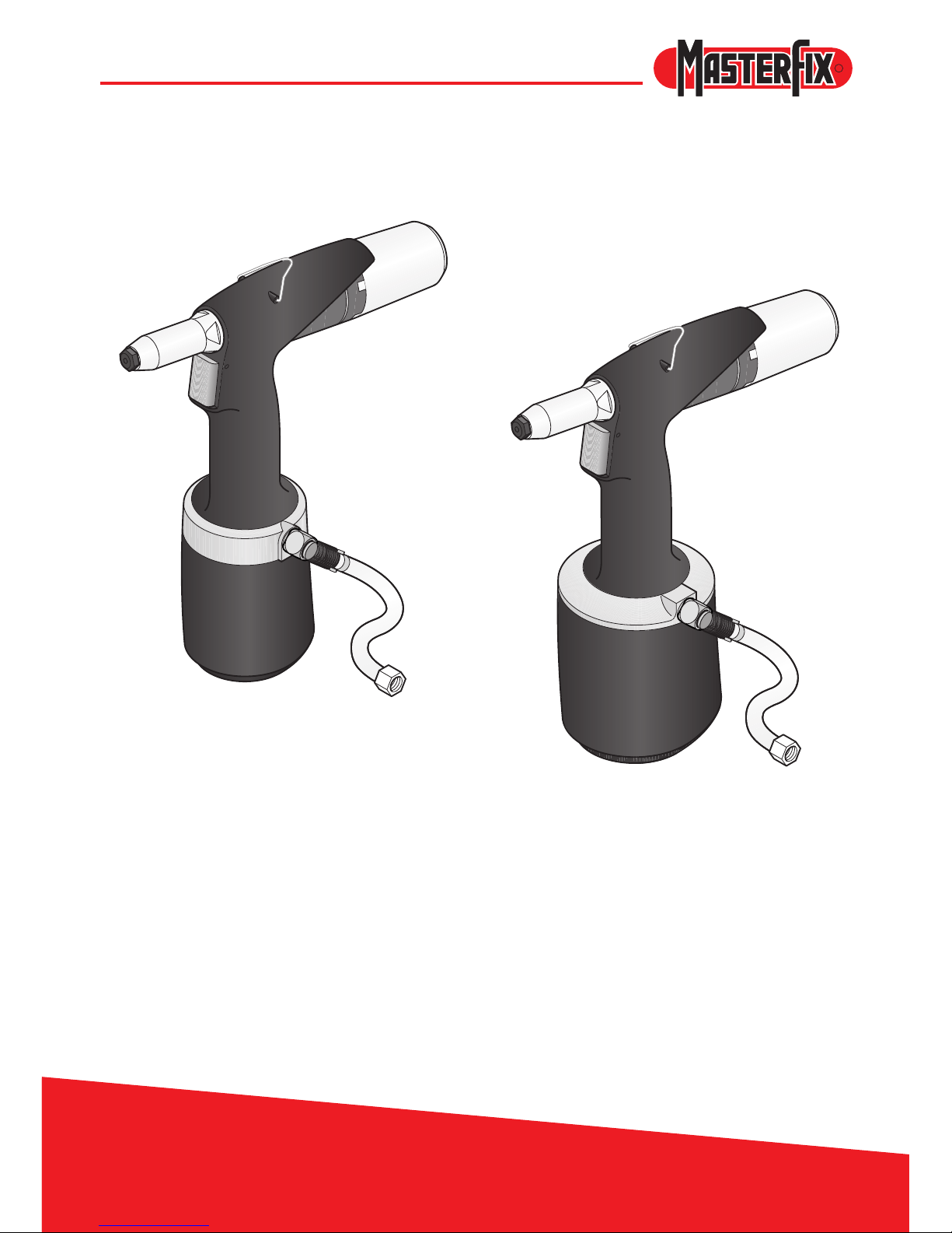
EZM1000 - 2000
R
Manual hydraulic / pneumatic
blind riveting tools
EZM1000
EZM2000
Page 2

EZM1000 - 2000
2
R
© 2008 Masterx Products bv
All rights reserved.
The information provided may not be reproduced and/or made public in any way and through any
means (electronically or mechanically) without prior explicit and written permission from
Masterx Products bv.
The information provided is based on the data known at the moment of the introduction of this product.
Masterx Products bv pursues a policy of continuous product improvement and therefore the products
may be subject to change.
The information provided is applicable to the product as delivered by Masterx Products bv.
Therefore, Masterx Products bv cannot be held liable for any damage resulting from deviations from
the original specications of the product.
The information available has been composed with the utmost care. However, Masterx Products
bv will not accept any liability with respect to any faults in the information nor for the consequences
thereof. Masterx Products bv will not accept any liability for damage resulting from activities carried
out by third parties.
The working names, trade names, registered trade marks, etc. used by Masterx Products bv should
not be considered as being free, pursuant to the legislation with respect to the protection of trade
marks.
Page 3

EZM1000 - 2000
3
R
Content
1 General .................................................................................... 4
1.1 This manual ...................................................................................................4
1.2. Icons in this manual .......................................................................................4
1.3 Discarding and the environment ....................................................................4
1.4 Service and maintenance .............................................................................. 4
1.5 Guarantee conditions .....................................................................................4
2 Safety ...................................................................................... 5
2.1 Safety instructions ......................................................................................... 5
2.2 Persons ..........................................................................................................5
2.3 Work environment ..........................................................................................6
2.4 Tools ..............................................................................................................6
2.5 Serial number ................................................................................................ 6
2.6 Type identifi cation .......................................................................................... 6
3 Main components .................................................................. 7
3.1 Components .................................................................................................. 7
3.2 Nose pieces ...................................................................................................7
4 Operation ................................................................................ 8
4.1 Controls .........................................................................................................8
4.2 Mandrel collector ........................................................................................... 9
4.3 Revolvable air outlet ...................................................................................... 9
4.4 360° Revolvable air supply unit .....................................................................9
5 Use ........................................................................................ 10
6 Maintenance ......................................................................... 12
6.1 Front sleeve .................................................................................................12
6.2 Clamping jaws .............................................................................................13
7 Trouble shooting .................................................................. 14
8 Technical data ...................................................................... 15
Page 4
EZM1000 - 2000
4
R
1 General
1.1 This manual
This manual describes the daily use of the tools. Carefully read this manual. Every user must be
acquainted with the contents of this manual. Strictly follow the instructions in this manual. Always carry
out the activities in the correct order. Keep this manual at a xed place. If the manual gets lost, you
can download it from www.masterx.com.
1.2. Icons in this manual
The following icons and symbols have been used in this manual:
CAUTION!
Procedures requiring extra attention.
Read the manual
Use safety goggles
Use hearing protection
Use safety gloves
Use spanner
25
2005
10015
Manometer
1.3 Discarding and the environment
Discarded tools are to be disposed of in accordance with the local regulations.
1.4 Service and maintenance
Masterx Products bv does not accept any liability for damage that results from non-observance of the
mentioned safety instructions (EEC directive 85/374).
1.5 Guarantee conditions
See the Masterx Products bv guarantee conditions attached.
Page 5
EZM1000 - 2000
5
R
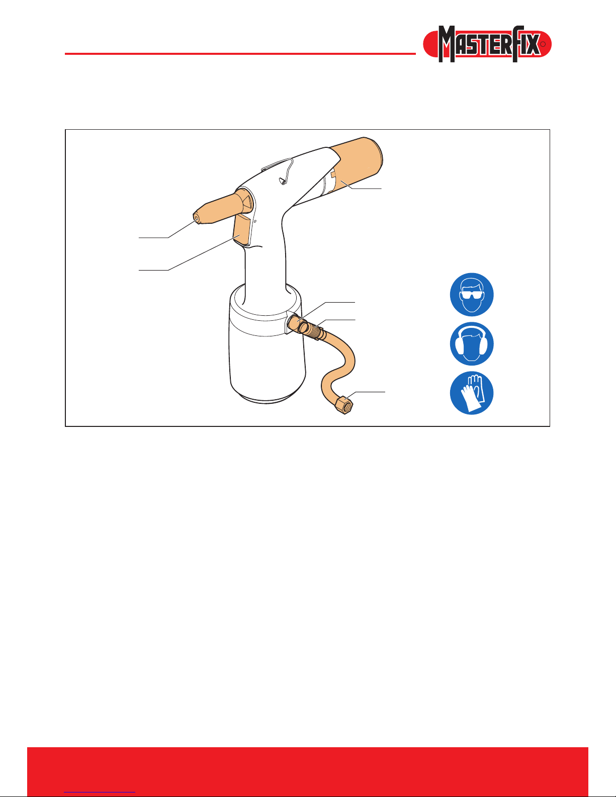
A Nose piece/front sleeve
B Mandrel collector
C Trigger
2 Safety
2.1 Safety instructions
D Safety valve
E Air supply closing valve
F Air connection
2.2 Persons
• Use safety goggles. This also applies to persons in the immediate surroundings.
• Use hearing protection when the sound level exceeds 85 dB(A).
• Use safety gloves, certain blind rivets can become very warm at some places.
• Keep your ngers away from the front when connecting the compressed air.
• Do not look straight into the tool (front and rear).
• Never direct the tool at persons.
F
B
D
E
A
C
Page 6
6
EZM1000 - 2000
R
2.3 Work environment
• Keep the work environment clean and neat.
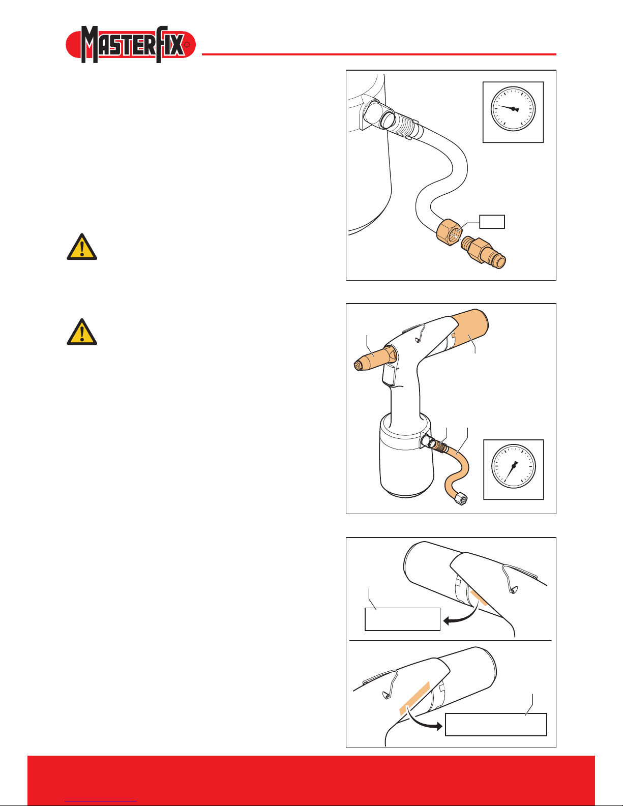
• Use dry, ltered and with anti-corrosive oil
lubricated air. If not available, put 0.1 ml
(approximately 5 drops) of anti-corrosive
lubricating oil in air connection of tool three
times each operating day.
• Work in a frost-free environment.
• The connection to the tools is G¼“.
A connection nipple has not been included.
Provide an appropriate solution yourself.
Set a constant air pressure to 5 - 7 bars
(maximum 7 bars).
2.4 Tools
Never use the tools
- when the nose piece/front sleeve (A) is
missing;
- when the mandrel collector (B) has not
been positioned
• Check the tools for damage before connecting
the air pressure.
• Keep the tools in an optimum condition.
• Switch off the closing valve (C) when the tools
are not used.
• Make sure that the exible connection hose (D)
is not pressurised when disconnecting.
• Do not modify the tools in any way.
• Only use the device for appropriate purposes.
2.5 Serial number
This is the place of the serial number (A) of the
tools.
2.6 Typeidentication
This is the place of the type identication (B) of
the tools.
25
0 bar
2005
10015
A
B
C D
G¼"
25
5-7 bar
2005
10015
XXXXX
EZM XXXX
A
B
Page 7
7
EZM1000 - 2000
R
3 Main components
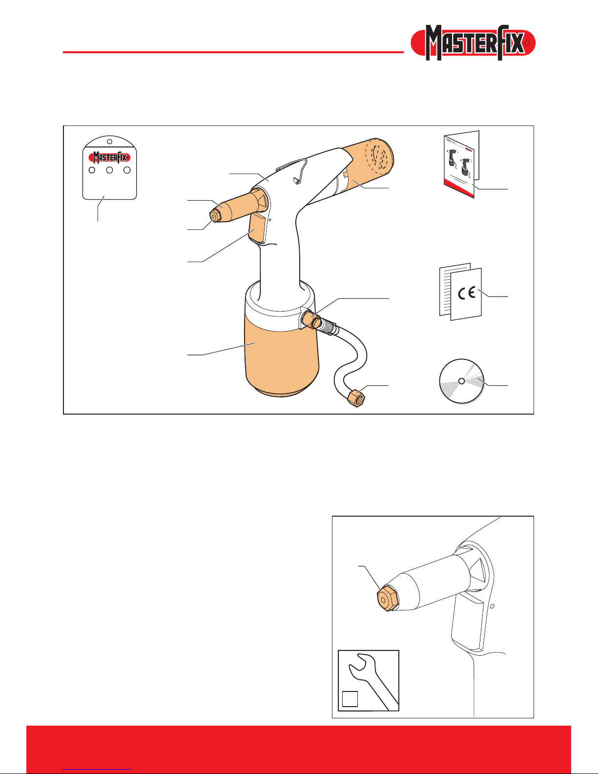
3.1 Components
A Nose pieces**
B Front sleeve
C Hydraulic body
D Mandrel collector
E Trigger
F Pneumatic body
G Safety valve
H Air connection
J Manual
K CE and guarantee form
L CD with manual in various languages
3.2 Nose pieces
The delivered box contains various nose pieces.
** EZM 1000: 3.0 – 5.0 mm
** EZM 2000: 4.0 – 6.4 mm
3,0/3,24,8/5,04,0
C
B
A
A
E
F
D
G
H
J
K
L
A
12
Page 8
EZM1000 - 2000
8
R
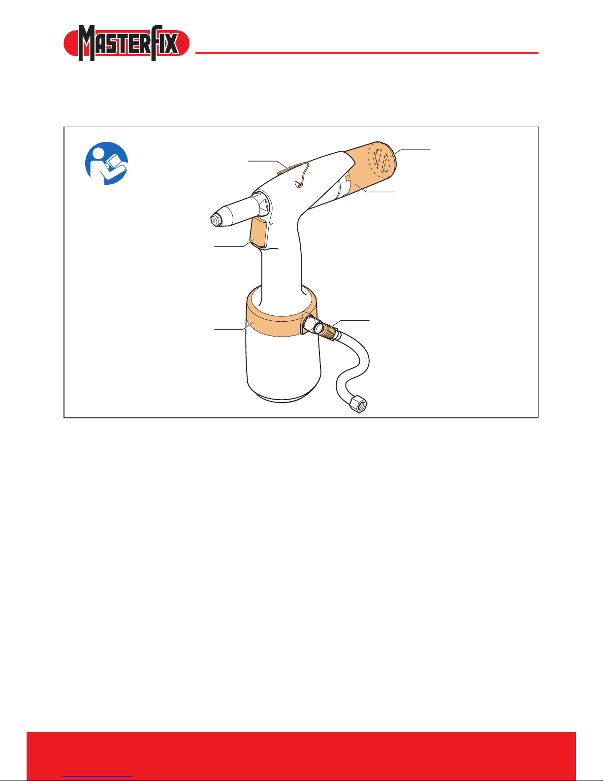
A Bracket
B Mandrel collector
C Air outlet
B
F
C
A
D
E
4 Operation
4.1 Controls
D Trigger
E 360° Revolvable air supply unit
F Air supply closing valve
Page 9
9
EZM1000 - 2000
R
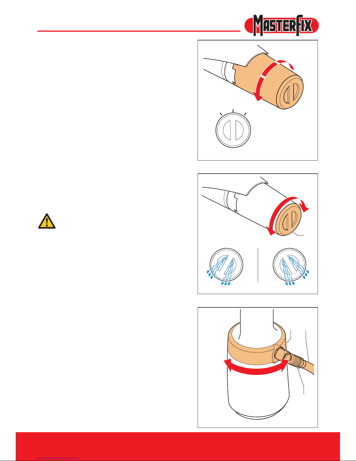
4.2 Mandrel collector
The purpose of the mandrel collector is to collect
the rest mandrel. The collector can be placed in
three positions.
A Position/remove.
B Lock – without extraction. Tilting the tools will
make sure that the mandrel will end up in the
collector.
C Lock – with extraction. The rest mandrel is
automatically blown into the collector.
4.3 Revolvable air outlet
The escaping airow can be set using the
revolvable air outlet (A) such, that people
experience a minimum of discomfort during work.
Do not remove this air outlet from the
mandrel collector.
4.4 360° Revolvable air supply unit
When the air hose (A) causes discomfort during
work, turn off closing valve (B). After this the
360º revolvable unit (C) can be turned into any
required position.
C
A
B
A
B
C
A
Page 10
EZM1000 - 2000
10
R
12
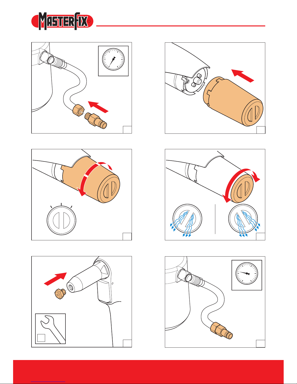
5 Use
A
B
C
25
0 bar
2005
10015
25
5-7 bar
2005
10015
1
3
2
4
5
6
Position the nipple (G1/4“).
Set the correct air pressure (see 2.3).
Position the mandrel collector.
Set the mandrel collector (see 4.2). Set the revolvable air outlet (see 4.3).
Mount the correct nose piece.
Page 11
EZM1000 - 2000
11
R
0
I
0
I
11
8
10
7
9
12
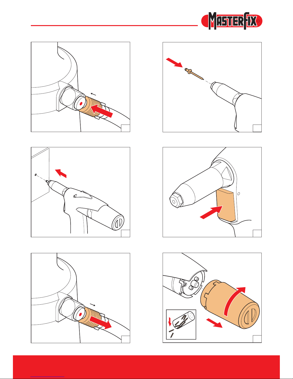
Turn on the closing valve.
Position the blind rivet.
Position the tools.
Turn off the closing valve.
Press the trigger.
Empty the mandrel collector after use.
Page 12
12
EZM1000 - 2000
R
23
A
B
6 Maintenance
Use safety goggles
Use hearing protection
Use safety gloves
6.1 Front sleeve
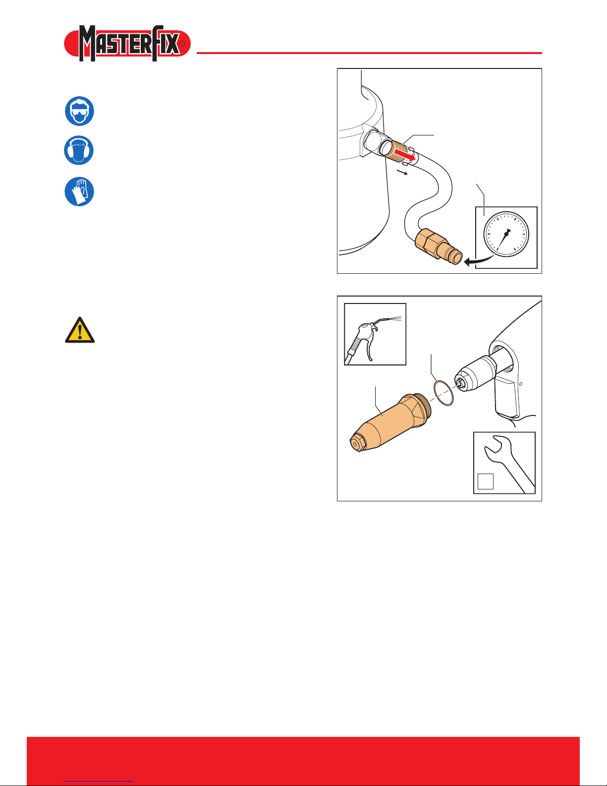
Turn off the closing valve (A) and disconnect the
air supply (B).
- Remove the front sleeve (A).
- Pay attention to the o-ring (B).
Clean the inside using an air blow gun.
25
0 bar
2005
10015
A
B
0
I
Page 13
13
EZM1000 - 2000
R
A
B
C
D
6.2 Clamping jaws
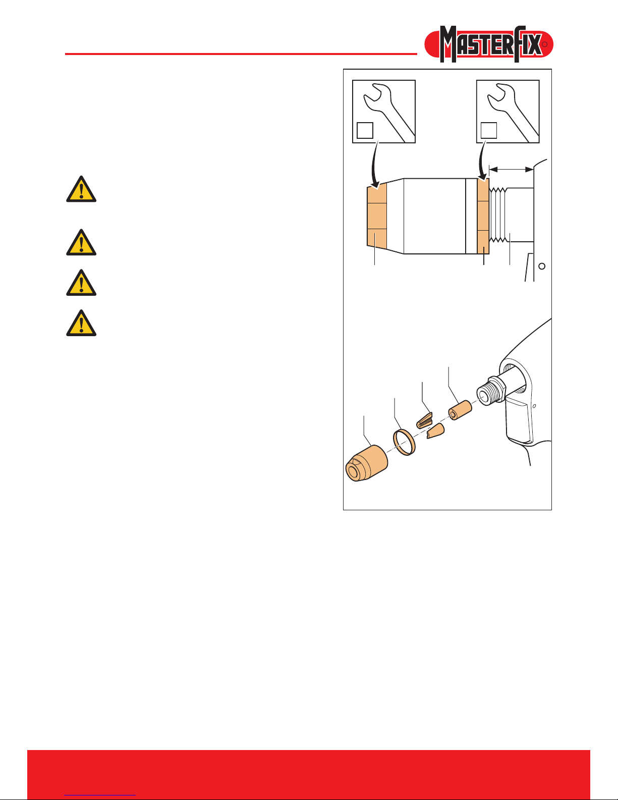
Remove the front sleeve, see 6.1.
Remove the clamping sleeve (A) and the Teon
ring (B), the 2 clamping jaws (C) and the jaw
pusher (D).
Clean the clamping jaws and the jaw pusher or
replace them.
Make sure that the spanner does not slip
off the locking nut (E). This may damage
the hydraulic piston rod (F).
Mounting is done in reverse order.
When mounting, lightly spray the inside of
the clamping sleeve with Teon spray.
Make sure that the locking nut is
positioned between 19-20 mm from the
hydraulic body.
15 17
19-20
FEA
Page 14
EZM1000 - 2000
14
R
7 Trouble shooting
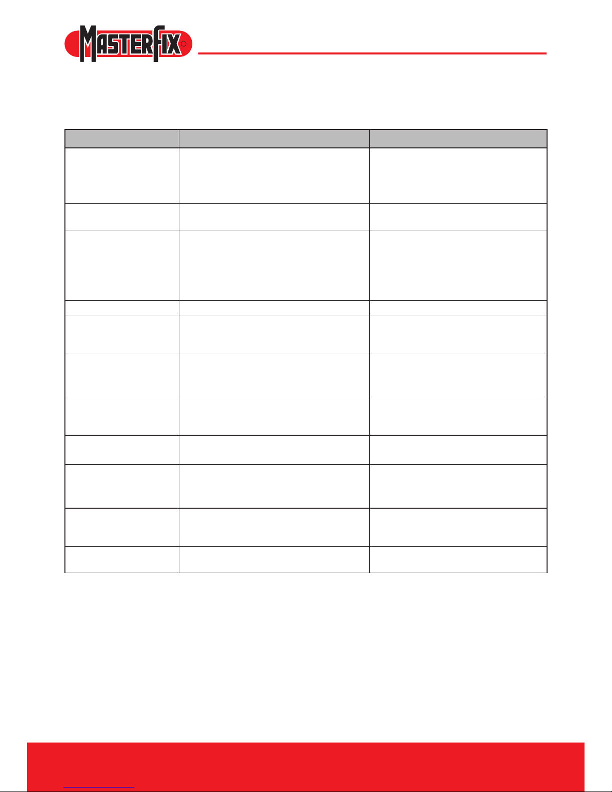
Problem Cause Corrective action
The tool does not work The tool has not been connected to the air
connection
The air supply closing valve is still closed
There is insufcient air pressure
Connect the tool to the air connection
Open the air supply closing valve
Use the correct air pressure 5-7 bar
Air is coming out of the
safety valve
The air pressure is too high Use the correct air pressure 5-7 bar
There is no or insufcient
extraction
The extraction has not been turned on
There is insufcient air pressure
The mandrel collector is full
The tool is blocked by rest mandrels
Check the position of the mandrel
collector
Use the correct air pressure 5-7 bar
Empty the mandrel collector
Remove the rest mandrel
The trigger does not work There is insufcient air pressure Use the correct air pressure 5-7 bar
The blind rivet cannot
be placed into the nose
piece
The incorrect nose piece has been mounted
The tool is blocked by rest mandrels
Mount the correct nose piece
Remove the rest mandrel
The blind rivet is not set
correctly
Contaminated or worn clamping jaws
There is insufcient air pressure
The capacity of the tool has been exceeded
Clear or replace the clamping jaws
Use the correct air pressure
Use the correct tool
The rest mandrel does
not release from the nose
piece
The incorrect nose piece has been mounted
The tool is blocked by rest mandrels
Mount the correct nose piece
Remove the rest mandrel
During setting the rivet
mandrel does not break
There is insufcient air pressure
The capacity of the tool has been exceeded
Use the correct air pressure
Use the correct tool
The rest mandrel is
not extracted into the
mandrel collector
The incorrect nose piece has been mounted
The tool is blocked by rest mandrels
The mandrel collector is full
Mount the correct nose piece
Remove the rest mandrel
Empty the mandrel collector
The air supply unit cannot
be turned 360°
The tool is still under air pressure Close the air supply closing valve and
depressurize the tool by turning on the
extraction or by operating the trigger
The tool does not perform
well consistently
Contact a service centre
Page 15
EZM1000 - 2000
15
R
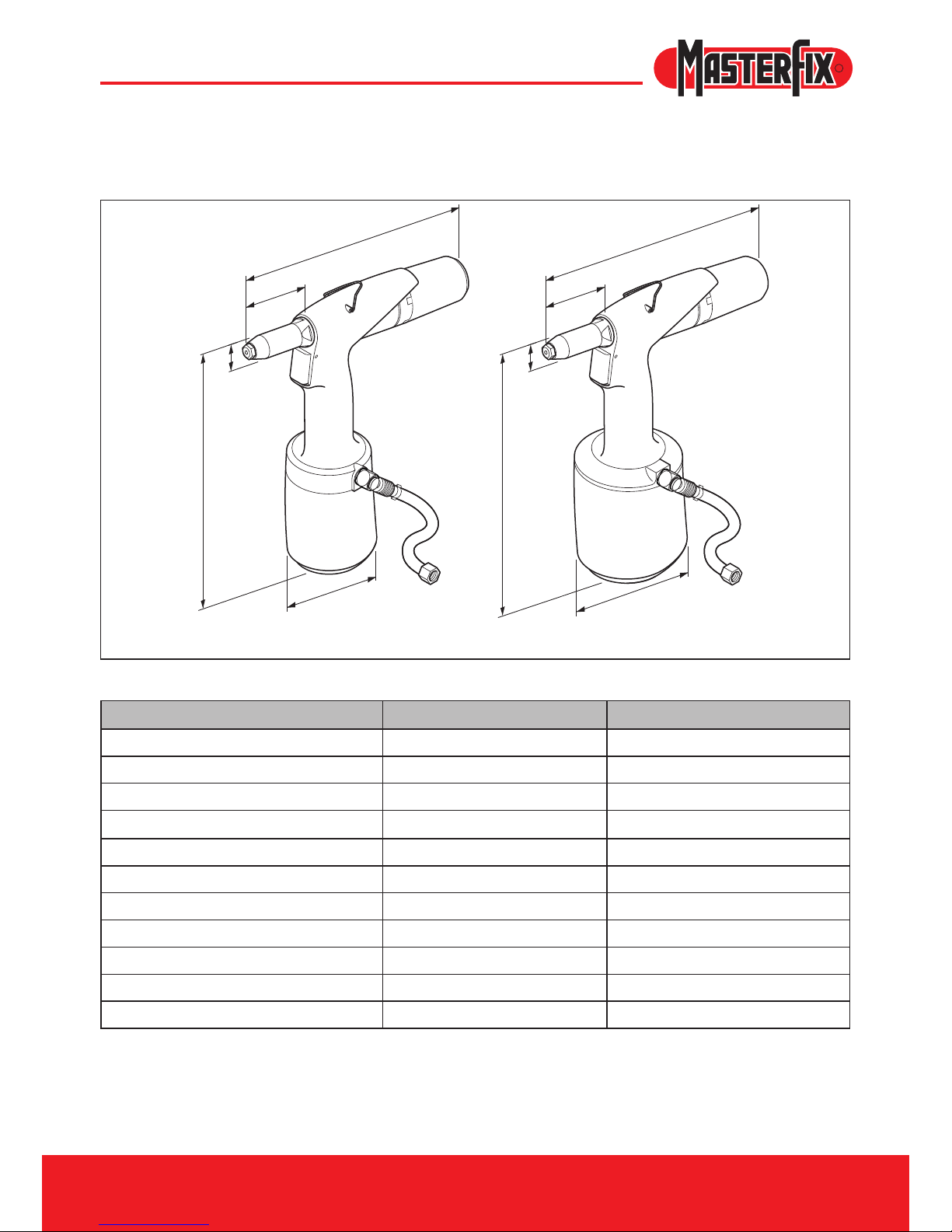
8 Technical data
H
S
L
P
D
P
H
S
L
D
EZM 1000 EZM 2000
EZM 1000 EZM 2000
H 264 mm 275 mm
L 272 mm 272 mm
ø D 102 mm 125 mm
P
70 mm 70 mm
ø S 23 mm 23 mm
Weight 1,25 kg 1,65 kg
Air pressure 5-7 bars 5-7 bars
Pull force (6 bars) 7.3 kN 12.5 kN
Air consumption (per stroke) 1.5 l 2.0 l
Stroke 17 mm 21 mm
Capacity (standard blind rivet) ø 3.0 – 5.0 mm (stainless steel) ø 4.0 – 6.4 mm (stainless steel)
Page 16

16
EZM1000 - 2000
R
TheNetherlands(HeadOfce)
Masterx Product b.v.
P.O. Box 21
6190 AA Beek
Phone: +31 (0)43 350 84 84
Fax: +31 (0)43 350 84 88
United Kingdom
Masterx Products UK Ltd.
Units 4a, b & d, Ring Road, Zone 2
Burntwood Business Park, Burntwood
Staffordshire, WS 3JQ
Phone: +44 (0) 1543 686 989
Fax: +44 (0) 1543 675 822
Spain
Black & Decker Ibérica, S.C.A.
Business Unit Masterx
Ctra. M-300, Km 29, 700
28802 Alcalá de Henares
Madrid
Phone: +34 (0)91 883 5730
Fax: +34 (0)91 880 8720
Poland
Masterfix Poland
ul. Daleka 16
60-124 Poznan
Phone: +48 (0)61 86 66 297/376
Fax : +48 (0)61 86 65 733
Website: www.masterfix.com
E-mail: [email protected]
 Loading...