

Page 1

28 Fr
Garantie de remplacement
Garantie de remplacement
Cet article Mastercraft comprend une garantie de réparation de trois (3) ans contre les
défauts de fabrication et de matériau(x). Mastercraft Canada consent, à sa discrétion, à
réparer ou à remplacer toute pièce défectueuse sans frais au cours de la période de garantie
convenue lorsque l'article, accompagné de la preuve d'achat, est retourné par l'acquéreur
initial. Exclusion : usure ou bris causés par un usage abusif ou inapproprié.
Cet article n'est pas garanti s'il est utilisé à des fins industrielles ou commerciales.
SERVICE D'ASSISTANCE TÉLÉPHONIQUE SANS FRAIS : 1 866 220-2097
Soudeuse à dévidage de fil-électrode
Please read and save these instructions. Read carefully before attempting to assemble, install, operate or maintain the product described.
Protect yourself and others by observing all safety information. Failure to comply with instructions could result in personal injury and/or
property damage! Retain instructions for future reference.
IN972900AV 2/05
Operating Instructions & Parts Manual WG2063, 58-8027-4
Wire Feed
Arc Welder
Description
This wire feed arc welder is designed to
be used on standard 115 V household
current. The welder is equipped with
infinite wire speed control to accurately
select the proper wire feed rate needed
for various welding conditions. Internal
components are thermostatically
protected.
This welding system is designed for use
with flux-core or MIG wires. As delivered
from the factory, this welder can weld
with .024” (.6 mm) to .030” (.8 mm)
diameter wire in MIG and .030” (.8 mm)
to .035” (.9 mm) diameter wire in fluxcore. A starter spool of .035” (.9 mm)
flux-core wire is included.
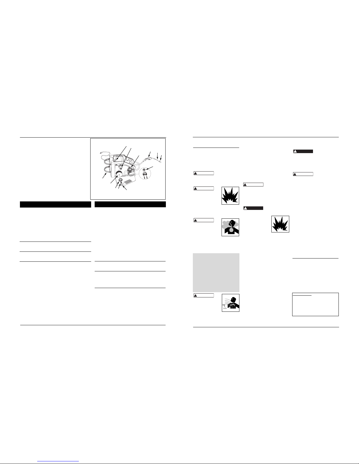
COMPONENTS AND CONTROLS
1. Work Clamp: connects to workpiece.
2. Torch with .035” tip.
3. Power Cord: plugs into 115 V outlet.
4. Light: illuminates if thermostat has
automatically shut welder off.
5. Infinite Wire Speed Control: turn
clockwise to increase wire speed and
counter-clockwise to decrease wire
speed.
6. Heat Selection Dial: selects welding
power and turns welder on. Four
selections are possible: 1 – 2 – 3 – 4.
7. MIG/Flux-core Polarity Selection Dial:
for changing to electrode positive or
negative polarity.
8. MIG Gas Hook-up
9. Wire Feed Compartment
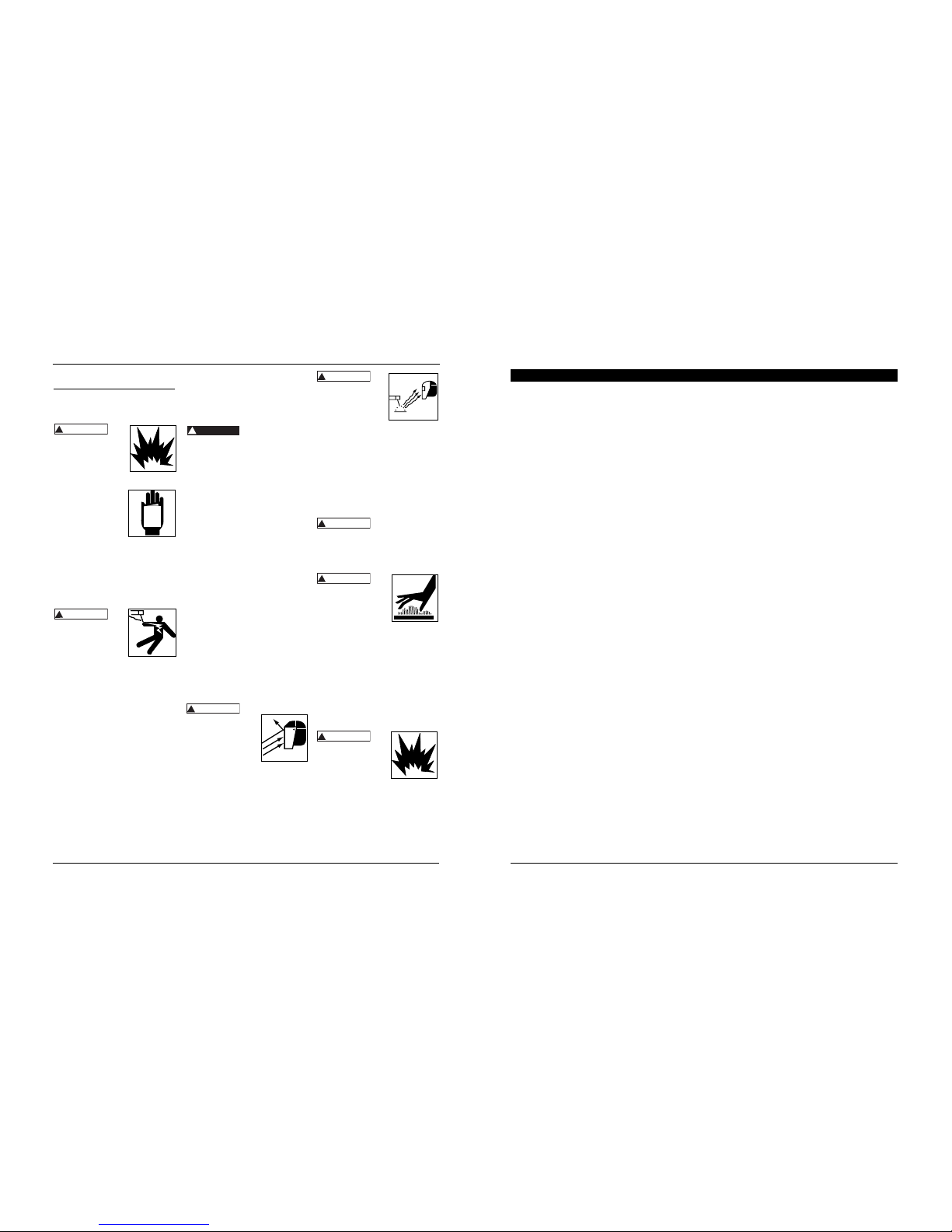
General Safety
Danger means a
hazard that will
cause death or serious injury if the
warning is ignored.
Warning means a
hazard that could
cause death or serious injury if the
warning is ignored.
Caution means a
hazard that may
cause minor or moderate injury if the
warning is ignored. It also may mean a
hazard that will only cause damage to
property.
!
CAUTION
!
WARNING
!
DANGE
R
See page 7 for supply cable
replacement instructions.
Unpacking
Welding accessories are packed inside
the wire feed compartment on the
side of the welder. When unpacking,
inspect carefully for any damage that may
have occurred during transit. Make sure
any loose fittings and screws, etc., are
tightened before putting unit into service.
Report any missing or damaged
items by calling 1-866-220-2097.
CIRCUIT REQUIREMENTS
This equipment
requires a dedicated
115 V circuit. Refer to the following chart
for correct circuit breaker or fuse rating.
Do not run other appliances, lights or
tools on this circuit while operating this
equipment. Extension cords are not
recommended. Blown fuses and tripped
circuit breakers can result from failure to
comply with this recommendation.
!
CAUTION
REMINDER: Keep your dated proof of purchase for warranty purposes! Attach it to this manual or file it for safekeeping.
Heat Circuit Breaker or
Selector Slow Blow Fuse
1-2-3 15 A
4 20 A
Fig. 1 - Welder Components and Controls
3
1
6
4
8
9
5
2
7
Page 2
27 Fr
CA ou courant alternatif : courant
électrique qui change de direction
périodiquement. Le courant à soixante
cycles voyage dans les deux directions
soixante fois par seconde.
Longueur de l’arc : la distance du bout
de l’électrode jusqu’au point où l’arc
contacte la surface de travail.
Métal commun : le matériel qui doit
être soudé.
Joint en bout : un joint entre deux
pièces qui sont alignées
approximativement dans le même plan.
Cratère : une flaque ou poche qui est
produite quand l’arc contacte le métal
commun.
CC ou courant continu : courant
électrique d’une direction seulement. La
polarité (+ ou -) détermine la direction
du courant.
CC polarité inversée : quand le porteélectrode est branché au pôle positif du
soudeur. La polarité inversée dirige plus
de chaleur dans l’électrode plutôt que
sur l’objet de travail pour l’utilisation sur
les matériaux plus minces.
CC polarité ordinaire : quand le porteélectrode est branché au pôle négatif du
soudeur. Plus de chaleur est dirigé vers
l’objet de travail pour une meilleure
pénétration des matériaux épais.
Électrode : un fil en métal enrobé
ayant approximativement la même
composition du matériel qui doit être
soudé.
Soudure en cordon : dimension
approx. d’un triangle, profil en travers,
qui uni les deux surfaces à angles droits
en soudure à recouvrement, en T ou en
coin.
Flux : un enduit qui produit un gaz
protecteur autour de l’endroit de
soudage. Ce gaz protège les métaux
contre les polluants dans l’air.
Soudure a l’arc fourré de flux
(FCAW) : ou sans-gaz est une méthode
de soudage utilisée avec une soudeuse à
arc à dévidage de fil électrode. Le fil de
soudeuse est tubulaire avec du flux à
l’intérieur pour protection.
Lexique de termes de soudage
Soudure à l’arc à gaz (GMAW) : ou
MIG est une méthode utilisée avec une
soudeuse à arc à dévidage de filélectrode. Le fil est solide et un gaz
inerte est utilisé pour protection.
Soudure à recouvrement : un joint
entre deux pièces en chevauchement.
Tension au repos : la tension entre
l’électrode et le collier de mise à la terre
quand il n’y a pas de flux de courant
(pas de soudage). Ceci détermine la
vitesse à laquelle l’arc est amorçé.
Chevauchement : se produit quand le
réglage d’intensité est trops bas. En ce
cas, le métal fondu tombe de l’électrode
sans se fondre dans le métal commun.
Porosité : des soufflures ou creux
formés pendant la solidification de la
soudure qui affaiblissent la soudure.
Pénétration : la profondeur que la
chaleur affecte l’objet pendant la
soudure. Une soudure de haute qualité
est celle qui atteint 100 % de
pénétration. C’est-à-dire que l’objet de
travail en entier a été chauffé et
solidifié à nouveau. Les endroits
chauffés devraient être visibles sur
l’inverse de la soudure.
Soudure à l’arc au métal enrobé
(SMAW) : est une méthode de soudage
qui utilise une électrode usable pour
soutenir un arc. L’enduit de flux fondu
sur l’électrode fournit la protection.
Scorie : une couche d’encrassement de
flux qui protège la soudure des oxydes
et autres polluants pendant le
refroidissement de la soudure. Enlever
la scorie après que la soudure s’est
refroidie.
Bavure : particules métalliques volantes
qui se refroidissent sur la surface de
travail. La bavure peut être diminuée si
vous utilisez un agent vaporisateur qui
résiste la bavure sur l’objet de travail
avant de souder.
Point de soudure : une soudure
utilisée pour tenir les pièces en
alignement jusqu’à ce que les soudures
actuelles soient complétées.
L’angle de déplacement : l’angle de
l’électrode dans la ligne de soudure.
Ceci varie entre 5º et 45º selon les
conditions.
Joint en T : placer le bord d’un
morceau de métal sur l’autre à un angle
de 90º.
Caniveau : une condition résultant
d’une intensité trop haute qui produit
une rainure dans le métal commun le
long des deux côtés du cordon de
soudure et sert à affaiblir la soudure.
Flaque de soudure : un volume de
métal fondu dans une soudure avant sa
soldification.
Cordon de soudage : une ou plusieurs
couches étroites de métal placé sur le
métal commun pendant que l’électrode
fond. La largeur du cordon de soudage
est typiquement deux fois le diamètre de
l’électrode.
Angle de travail : l’angle de l’électrode
de l’horizontal mésuré à angle droit de
la ligne de soudure.
WG2063, 58-8027-4
2
Wire Feed Arc Welder
General Safety
(Continued)
NOTE: Note means any additional
information pertaining to the product
or its proper usage.
Always keep a fire
extinguisher accessible
while performing arc
welding operations.
Before starting or
servicing any electric arc welder, read
and understand all
instructions. Failure
to follow safety
precautions or
instructions can
cause equipment
damage and/or serious personal
injury or death.
All installation, maintenance, repair
and operation of this equipment
should be performed by qualified
persons, only in accordance with
national, provincial and local codes.
Improper use of electric
arc welders can cause
electric shock, injury,
and death! Take all
precautions described in
this manual to reduce the possibility of
electric shock.
Verify all components of the arc
welder are clean and in good
condition prior to operating. Make
sure insulation is not damaged on
wire feed gun, power cord and
cables. Always repair or replace
damaged components before
operating the welder. Always keep
welder panels, shields, etc. in place
when operating welder.
Always wear dry, protective
clothing, welding gloves and
insulated footwear when operating
unit.
Always operate welder in a clean,
dry, well-ventilated area. Do not
operate welder in humid, wet, rainy
or poorly ventilated areas.
Make sure workpiece is properly
!
WARNING
!
WARNING
supported and grounded prior to
beginning any electric arc welding
operation.
Spread out coiled welding cable
before use to avoid overheating and
damage to insulation.
Never immerse
wire or wire feed
gun in water. If welder becomes wet for
any reason, be absolutely certain it is
completely clean and dry before use!
Always shut equipment off and
unplug power cord prior to moving
the unit.
Always attach the work lead first.
Verify workpiece is securely
grounded.
Always shut off electric arc welding
equipment when not in use and cut off
any excess wire from wire feed gun.
Never allow any part of the body to
touch flux-core wire and ground or
grounded workpiece at the same
time.
Awkward welding conditions and
positions can be electrically hazardous.
When crouching, kneeling or at
elevations, be sure to insulate all
conductive parts, wear appropriate
protective clothing and take
precautions to prevent injury from falls.
Never attempt to use this equipment
at current settings or duty cycles higher
than specified on equipment labels.
Never use an electric arc welder to
thaw frozen pipes.
Flying sparks and hot
metal can cause injury.
As welds cool, slag can
be thrown off. Take all
precautions described in
this manual to reduce
the possibility of injury from flying
sparks and hot metal.
Wear ANSI approved face shield or
safety glasses with side shield
protection when chipping or
grinding metal parts.
Wear ear plugs when welding
overhead to prevent spatter or slag
from falling into ears.
!
WARNING
!
DANGE
R
Electric arc welding
operations produce
intense light and heat
and ultraviolet (UV)
rays. This intense light
and UV rays can cause injury to eyes and
skin. Take all precautions described in
this manual to reduce the possibility of
injury to eyes and skin.
All persons operating this equipment
or in the area while equipment is in
use, must wear protective welding gear
including: welding helmet or shield
with at least shade #10 lens, flameresistant clothing, leather welding
gloves and full foot protection.
Never look at arc
welding operations
without eye protection as described
above. Never use a shade filter lens
that is cracked, broken, or rated below
number 10. Warn others in the area not
to look at the arc.
Electric arc welding
operations cause sparks
and heat metal to
temperatures that can
cause severe burns! Use
protective gloves and clothing when
performing any metal working
operation. Take all precautions described
in this manual to reduce the possibility
of skin and clothing burns.
Make sure all persons in welding
area are protected from heat, sparks
and ultraviolet rays. Use additional
face shields and flame-resistant
barriers as needed.
Never touch workpieces until
completely cooled.
Heat and sparks
produced during
electric arc welding and
other metal working
operations can ignite
flammable and explosive materials!
Take all precautions described in this
manual to reduce the possibility of
flames and explosions.
Remove all flammable materials
within 35’ (10.7 m) of welding arc. If
removal is not possible, tightly cover
flammable materials with fire-proof
covers.
!
WARNING
!
WARNING
!
WARNING
!
WARNING
MANUAL
Page 3
26 Fr
Soudeuse à dévidage de fil-électrode
1 Assemblage du chalumeau et
tuyau (MIG) WC403660AV 1
2 Pointe de contact - 0,035 po (0,9 mm) WT501400AV 1
Pointe de contact optionnelle 0,024 po (0,6 mm) paquet de 4 WT501200AJ †
Pointe de contact optionnelle 0,030 po (0,8 mm) paquet de 4 WT501300AJ †
Pointe de contact optionnelle -
0,035 po (0,9 mm) paquet de 4 WT501400AJ †
3 Buse WT502100AV 1
4 Rouleau entraîneur WC500805AV 1
5 Assemblage du tablier d'entraînement WC500800AJ 1
6 Broche et grille WC707018AV 1
7 Dispositif de retenue de bobine WC707024AV 1
8 Ressort de retenue de bobine WC707026AV 1
9 Anneau de retenue de bobine WC707023AV 1
10 Fil de soudure fourré - 0,030 po (0,8 mm)
2 lb (0,9 kg) Rouleau (E71T-GS) WE200001AV †
Fil de soudure fourré - 0,030 po (0,8 mm)
10 lb (4,5 kg) Rouleau (E71T-GS) WE201000AV †
Fil de soudure fourré - 0,035 po (0,9 mm)
2 lb (0,9 kg) Rouleau (E71T-GS) WE200501AV †
Fil de soudure fourré - 0,035 po (0,9 mm)
10 lb (4,5 kg) Rouleau (E71T-GS) WE201500AV †
Fil de soudure MIG - 0,024 po (0,6 mm)
2 lb (0,9 kg) Rouleau (ER70S6) WE300001AV †
No de
réf. Description No de pièce Qté.
Fil de soudure MIG - 0,024 po (0,6 mm)
11 lb (5 kg) Rouleau (ER70S6) WE301500AV †
Fil de soudure MIG - 0,030 po (0,8 mm)
2 lb (0,9 kg) Rouleau (ER70S6) WE300501AV †
Fil de soudure MIG - 0,030 po (0,8 mm)
11 lb (5 kg) Rouleau (ER70S6) WE302000AV †
Fil de soudure MIG - 0,035 po (0,9 mm)
2 lb (0,9 kg) Rouleau (ER70S6) WE301001AV †
Fil de soudure MIG - 0,035 po (0,9 mm)
11 lb (5 kg) Rouleau (ER70S6) WE302500AV †
Fil de soudure MIG - 0,030 po (0,8 mm)
1 lb (0,45 kg) Aluminium (ER5356) WE303001AV †
11 Dispositif de retenue de la bouteille
avec 4 vis WC302600AJ 1
12 Raccord de tuyau barbelé (externe) WC403900AV 1
Raccord rapide (interne) WC403901AV 1
13 Tuyau de gaz - 22 po (55,9 cm) WC403902AV 1
14 Collier de serrage de tuyau WC403903AV 2
15 Régulateur WC802500AV 1
16 Masque de soudage à main
(lentille non incluse) WC801700AV 1
17 Lentille ombragée
(pour masque de soudage à main) WC801100AV 1
18 Marteau/brosse de piquage WC803400AV 1
19 Décalque de sécurité DK688509AV 1
20 Trousse de barre-omnibus de polarité WC403128AV 1
Pas indiquée
† Accessoire optionnel
No de
réf. Description No de pièce Qté
3
4
1
8
9
2
11
10
7
12
6
5
Figure 15 - Pièces de rechange
Pour pièces de rechange ou
assistance technique, appeler
1 866 220-2097
S’il vous plaît fournir l’information suivante :
- Numéro de modèle
- Numéro de série (si applicable)
- Numéro et description de la pièce
Liste de pièces de rechange
General Safety
(Continued)
Do not operate electric arc welder in
areas where flammable or explosive
vapours may be present.
Take precautions to ensure flying
sparks and heat do not cause flames
in hidden areas, cracks, etc.
Fire hazard! Do not
weld on containers
or pipes that contain or have contained
flammable materials or gaseous or liquid
combustibles.
Arc welding closed
cylinders or containers
such as tanks or drums
can cause explosion if
not properly vented!
Verify that any cylinder or container to
be welded has an adequate ventilation
hole, so that expanding gases can be
released.
Do not breathe fumes
produced by arc
welding operation.
These fumes are
dangerous. If welding
area cannot be adequately ventilated,
be sure to use an air-supplied
respirator.
Keep head and face out of welding
fumes.
Extremely toxic fumes are created
when galvanized or cadmium-plated
metals or metals which contain zinc,
mercury or beryllium are heated.
Complete the following precautions
before performing electric arc
welding operations on these metals:
a. Remove coating from base metal.
b. Make sure welding area is well
ventilated.
c. Use an air-supplied respirator.
The electromagnetic field
generated during arc
welding may interfere
with the operation of
various electrical and
electronic devices such as cardiac
pacemakers. Persons using such devices
should consult with their physician prior
!
WARNING
!
WARNING
!
WARNING
!
WARNING
equipment, and CGA publication P-1
listed in Safety Standards.
Never use
flammable gasses
with MIG welders. Only inert or nonflammable gasses such as carbon
dioxide, argon, helium or mixtures of
one or more of these gasses are
suitable for MIG welding.
Never lift cylinders
off the ground by
their valves or caps or with chains or
slings.
ADDITIONAL SAFETY STANDARDS
ANSI Standard Z49.1 from American
Welding Society.
Safe Handling of Compressed Gases
in Cylinders
CGA Pamphlet P-1, from Compressed Gas
Association.
Code for Safety in Welding and
Cutting
CSA Standard W117.2, from Canadian
Standards Association.
Cutting And Welding Processes
NFPA Standard 51B, from National Fire
Protection Association.
Safe Practices For Occupational And
Educational Eye And Face Protection
ANSI Standard Z87.1, from American
National Standards Institute.
Installation
LOCATION
Selecting the proper location can
significantly increase performance,
reliability and the life of the arc welder.
For best results use welder in a clean
and dry environment. Dust and dirt
in the welder retains moisture and
increases the wear of moving parts.
!
WARNING
!
DANGE
R
3
to performing any electric arc welding
operations.
Route wire gun and work cables
together and secure with tape when
possible.
Never wrap arc welder cables around
the body.
Always position wire gun and work
leads on the same side of the body.
Exposure to electromagnetic fields
during welding may have other
health effects which are not known.
Always be sure
welding area is
secure and free of hazards (sparks,
flames, glowing metal or slag) prior to
leaving. Be sure equipment is turned off
and excess wire is cut off. Be sure cables
are loosely coiled and out of the way. Be
sure all metal and slag has cooled.
Cylinders can explode if damaged.
Shielding gas cylinders
contain gas under high
pressure. If damaged, a
cylinder can explode.
Since gas cylinders are
normally part of the
welding process, be
sure to treat them carefully.
Protect compressed gas cylinders
from excessive heat, mechanical
shocks and arcs.
Install and secure cylinders in an
upright position by chaining them
to stationary support or equipment
cylinder rack to prevent falling or
tipping.
Keep cylinders away from any
welding or other electrical circuits.
Never allow a welding electrode to
touch any cylinder.
Use only correct shielding gas
cylinders, regulators, hoses and
fittings designed for the specific
application; maintain all parts
properly.
Turn face away from valve outlet
when opening cylinder valve.
Keep protective cap in place over
valve except when cylinder is in use
or connected for use.
Read and follow instructions on
compressed gas cylinders, associated
!
DANGE
R
!
WARNING
WG2063, 58-8027-4
Specifications:
Power: 115 V, 15 or 20 A
Metal thickness: 24-gauge to 3/16”
Duty-cycle: 20% at 70 A
Output current: 40–70 A
Wire used: MIG 0.024, 0.030” or
flux-core 0.030, 0.035”
Page 4
25 Fr
WG2063, 58-8027-4
Guide de dépannage - soudures
Symptôme Cause(s) possible(s) Mesure corrective
Cordon de soudure trop
mince par intervalles.
Cordon de soudure trop
épais par intervalles.
Enfoncements en lambeaux
au bord de la soudure.
Le cordon de soudure ne
pénètre pas le métal
commun.
Le fil crache et se colle.
1. Vitesse de déplacement rapide
ou irrégulière.
2. Réglage de chaleur de sortie
trop bas.
1. Vitesse de déplacement lente
ou irrégulière.
2. Réglage de chaleur de sortie
trop élevé.
1. Vitesse de déplacement trop
rapide.
2. Vitesse de fil trop rapide.
3. Réglage de chaleur de sortie
trop élevé.
1. Vitesse de déplacement
irrégulière.
2. Réglage de chaleur de sortie
trop bas.
3. Manque de/niveau bas de gaz
protecteur.
4. Type de gaz incorrect
(aluminium).
5. Cordon prolongateur trop long.
6. Accumulation possible d’oxydes
sur la surface (aluminium).
1. Fil humide.
2. Vitesse de fil trop rapide.
3. Type de fil incorrect.
4. Manque de/niveau bas de gaz
protecteur.
1. Diminuer et maintenir une vitesse de déplacement
constante.
2. Augmenter le réglage de chaleur de sortie.
1. Augmenter et maintenir une vitesse de déplacement
constante.
2. Diminuer le réglage de chaleur de sortie.
1. Diminuer la vitesse de déplacement.
2. Diminuer la vitesse de fil.
3. Diminuer le réglage de chaleur de sortie.
1. Diminuer et maintenir une vitesse de déplacement
constante.
2. Augmenter le réglage de chaleur de sortie.
3. Utiliser le gaz pour la méthode MIG ou remplir la
bouteille.
4. Utiliser le gaz Argon 100 % seulement.
5. N’utilisez pas un cordon prolongateur de plus que 20 pi
de long.
6. Bien nettoyer la surface avec une brosse métallique
seulement.
1. Utiliser un fil sec et l’entreposer dans un endroit sec.
2. Diminuer la vitesse de fil.
3. Utilisez le fil fourré de flux si vous n’utilisez pas de gaz.
4. Utiliser le gaz pour la méthode MIG ou remplir la
bouteille.
Reassemble spindle cover, spring,
and spindle lock, turning knob 1/4
rotation clockwise to tighten.
4. Hold wire and cut the wire end from
spool. Do not allow wire to
unravel. Be sure end of wire is
straight and free of burrs.
5. Pull tension screw down on drive
mechanism. This allows initial
feeding of wire into gun liner by
hand.
6. Lift up swing arm. Feed wire through
feed guide tube, across roller and into
wire liner. Pull down swing arm. Pull up
on wire feed tension screw. Adjust
tension (do not over-tighten). Close
side panel.
7. Remove nozzle by turning counterclockwise, then unscrew contact tip
from end of welding torch (See
Figure 4). Plug welder into a proper
power supply receptacle.
8. Turn on welder and set wire speed
4
Wire Feed Arc Welder
Installation (Continued)
Place welder in an area with at the
least 12” (30.5 cm) of ventilation space
at both the front and rear of unit. Keep
all obstructions out of this ventilation
space.
Store welding wire in a clean, dry
location with low humidity to
prevent oxidation.
Use a properly grounded receptacle
for the welder and ensure welder is
the only load on power supply
circuit. Refer to chart on page 1 for
correct circuit capacity.
Use of an extension cord is not
recommended when using the arc
welder. Voltage drop in the extension
cord may significantly degrade
performance of the welder.
Assembly
BOTTLE RETAINER ASSEMBLY
Attach bottle retainer to welder as
shown (Fig. 2).
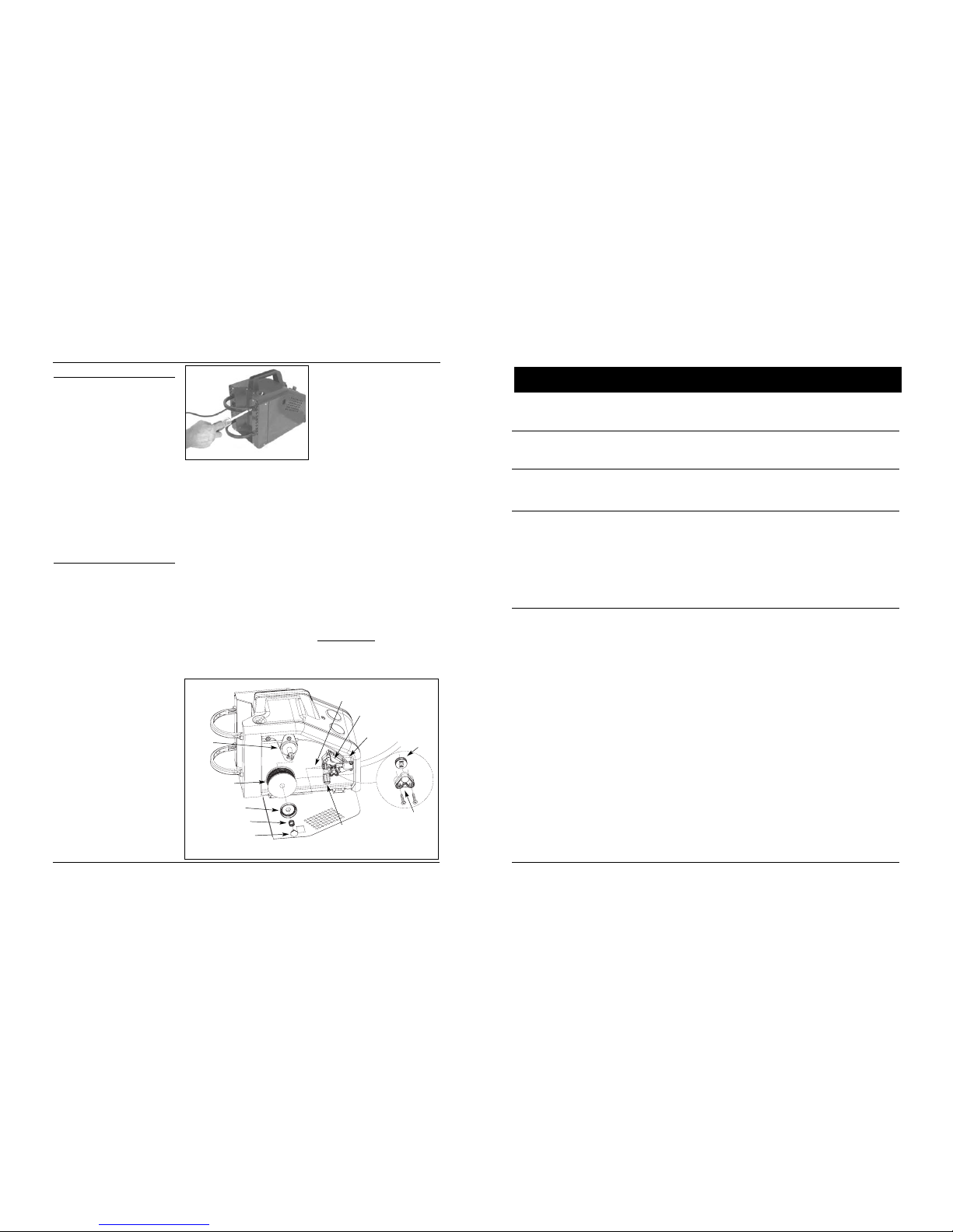
WIRE INSTALLATION
NOTE: Before installing welding wire,
be sure:
a. Diameter of welding wire matches
groove in drive roller on wire feed
mechanism (See Fig. 3). The drive
roller is marked with metric sizes:
.6 mm = .024”
.8 –.9 mm = .030–.035”
b. Wire matches contact tip in end of
gun. (See Fig. 4).
A mismatch on any item could cause the
wire to slip and bind.
NOTE: Always maintain control of loose
end of welding wire to prevent
unspooling.
1. Verify unit is off and open door
panel to expose wire feed
mechanism.
2. Remove the spindle lock by pushing
in and rotating 1/4 turn counterclockwise. Then remove spring and
spindle cover.
3. Install wire spool onto spindle so
wire will feed from bottom of spool.
Do not cut the wire loose yet.
rate to 10. Activate gun trigger until
wire feeds out 1 1/2” past the torch
end. Turn welder off.
9. Carefully slip contact tip over wire
and screw tip into torch end. Install
nozzle by turning clockwise (See
Figure 4). Cut wire off approximately
1/4" from nozzle end.
DUTY-CYCLE THERMAL/OVERLOAD
PROTECTION
The duty-cycle is the percentage of
actual arc welding time that can occur in
a ten minute interval. For example, at a
20% duty-cycle, actual welding can
occur for two minutes, then the welder
must cool for eight minutes.
Internal components of this welder are
protected from overheating with an
automatic thermal switch. A yellow
lamp is illuminated on the front
panel if the duty-cycle is exceeded.
Welding operations may continue when
the yellow lamp is no longer illuminated.
POLARITY SELECTION DIAL
A MIG wire requires electrode positive
electrical polarity. A flux-core wire
requires electrode negative electrical
polarity. The welder is factory set for
flux-core wire.
To Change Polarity
(See Figure 5a)
NOTE: The arrow on the Polarity Cover
points to the current polarity setting.
Fig. 2 - Bottle Retainer Assembly
Spindle
Welding wire
spool
Spindle cover
Spring
Spindle lock
Tension screw
Feed guide tube
Swing arm
Drive deck
Roller
support
Roller
Fig. 3 - Weld Wire Routing
Page 5
24 Fr
Soudeuse à dévidage de fil-électrode
Guide de dépannage - soudeuse à arc à dévidage de fil-électrode
Symptôme Cause(s) possible(s) Mesure corrective
Ligne d'assistance téléphonique sans frais : 1 866 220-2097
1. Facteur d’utilisation dépassé.
2. Raccord au collier de mise à la
terre insuffisant.
3. Interrupteur défectueux.
4. Disjoncteur ou fusible sauté.
1. Bout du pistolet de taille
incorrecte.
2. Chemise du pistolet obstruée
ou endommagée.
3. Bout du pistolet obstrué ou
endommagé.
4. Rouleau d’entraînement usé.
5. Tension insuffisante.
1. Scorie dans la buse du pistolet.
2. Anneau d'isolant fondu/expiré.
1. Raccordement insuffisant.
2. Utilisation d’un cordon
prolongateur trop long.
1. Permettre que le soudeur se refroidisse jusqu'à ce que la
lampe s'éteigne.
2. S’assurer que tous les raccordements soient sûrs et que la
surface d’attache soit propre.
3. Remplacer l’interrupteur.
4. Réduire la charge sur le circuit, rajuster le disjoncteur ou
remplacer le fusible.
1. Utiliser un bout de taille correcte.
2. Nettoyer ou remplacer la chemise du pistolet.
3. Nettoyer ou remplacer le bout du pistolet.
4. Remplacer.
5. Serrer la vis de tension.
1. Nettoyer la scorie de la buse du pistolet.
2. Remplacer la buse.
1. S’assurer que tous les raccordements soient sûrs et que la
surface d’attache soit propre.
2. N’utilisez pas un cordon prolongateur de plus que 20 pi
de longueur.
Manque de puissance.
Le fil s’emmêle au rouleau
d’entraînement.
La buse du pistolet arc à la
surface de travail.
Collier de mise à la terre
ou câble deviennent
chauds.
1. Fil étranglé.
2. Plus de fil.
3. Tension insuffisante.
4. Chemise de fil usée.
5. Fil débranché à l’intérieur.
6. Pointe de contact obstruée.
1. Vitesse de fil trop lente.
2. Vitesse de déplacement trop
lente ou chaleur trop élevée.
1. Réglage de vitesse du fil.
2. Taille de pointe de contact
trop large.
3. Polarité réglée incorrectement.
4. Rouleau entraîneur glisse.
5. Bouteille à gaz vide.
1. Recharger le fil.
2. Remplacer la bobine de fil.
3. Serrer la vis de tension si le fil patine.
4. Remplacer la chemise.
5. Appeler la ligne d’assistance sans frais.
6. Remplacer la pointe de contact.
1. Vitesse de fonctionnement entre 7 et 10.
2. Augmenter la vitesse de déplacement ou diminuer le
réglage de chaleur.
1. Mettre au point au bon réglage (1-5 acier doux; 5-10
aluminium).
2. Remplacer la pointe de contact.
3. Inverser la polarité.
4. Augmenter la tension.
5. Remplacer la bouteille à gaz.
Le fil ne s’avance pas.
Le fil (aluminium) brûle
dans la pointe ou le métal
(aluminium) produit des
bulles ou brûle à travers.
Soudure crache et colle.
5. Reinstall four nuts and tighten
securely.
6. Reinstall polarity cover and cover
screw.
7. Make sure arrow on polarity cover
points to desired setting.
Shielding Gas Preparation
Improper handling
and maintenance of
compressed gas cylinders and regulators
can result in serious injury or death!
Always secure gas cylinders to tank
bracket kit, a wall or other fixed support
to prevent cylinder from falling over.
Read, understand and follow all
compressed gas and equipment
warnings in the safety instructions.
NOTE: Shielding gas is not required if
flux-core wire is used.
!
DANGER
Assembly (Continued)
TOOLS NEEDED: screwdriver and 10
mm socket wrench.
1. Unplug power cord from socket.
2. Remove cover screw and polarity
cover.
3. Remove four nuts from polarity
studs.
4. Pull out polarity bus bar and rotate
it 90°. Reinsert aligning groove with
the correct rib in polarity box.
Upper right rib marks the MIG
position; lower right rib marks the
flux-core position. (See Figure 5b.)
GAS TYPES
There are 3 types of gas generally used
for gas metal arc welding: 100% argon,
a mixture of 75% argon and 25%
carbon dioxide (C25) or 100% carbon
dioxide.
Use ONLY the type
of gas recommended for your welder. Use ONLY an inert,
non-flammable type of gas. Failure to do
so will result in a very hazardous
situation.
NOTE: 100% carbon dioxide is not
recommended due to unsatisfactory
weld beads.
The 75/25 mixture is recommended for
general steel welding. For aluminum
welding, use 100% argon. Secure
cylinder on your arc welder (or other
support) to prevent the cylinder from
falling over.
REGULATOR
An adjustable regulator without gauges
is supplied with this arc welder. The
regulator provides a constant shielding
gas pressure and flow rate during arc
welding. Each regulator is designed to
be used with a specific gas or mixture of
gases. The argon and argon mixture use
the same type of thread. The 100%
carbon dioxide uses a different thread
type. Adaptors are available at welding
gas suppliers.
HOSE AND REGULATOR HOOKUP
PROCEDURE
Cylinder gas is under high pressure.
Point cylinder outlet away from
yourself and any bystanders before
opening.
1. With cylinder securely installed, stand
on side of cylinder opposite cylinder
outlet then remove cylinder cap and
open valve slightly by turning
counter-clockwise. When gas is
emitted from cylinder, close valve by
turning clockwise. This will blow out
dust or dirt that may have
accumulated around valve seat.
2. Install regulator onto cylinder valve.
Tighten stem nut securely to gas
valve.
!
WARNING
!
DANGE
R
5
WG2063, 58-8027-4
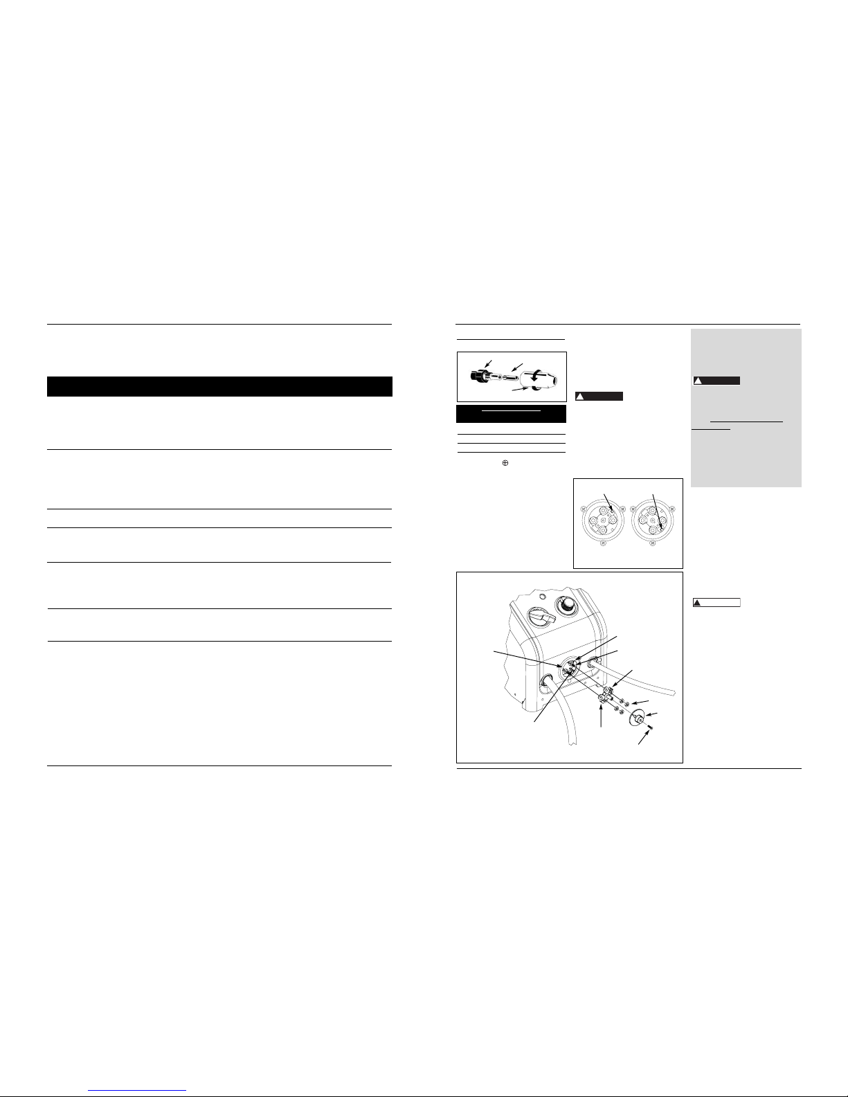
Figure 5a
Polarity box
Flux rib
Polarity bus bar
Nuts
Cover screw
Polarity
cover
Groove
Polarity studs
MIG rib
Fig. 5b
MIG position
Flux position
Upper right—
MIG rib
Lower right—
Flux rib
Contact Tip Markings
Mark Wire Size
0.6 mm .024"
0.8 mm .030"
0.9 mm .035"
Torch Diffuser
Contact Tip
Nozzle
Fig. 4 – Torch Nozzle
Page 6

doit être bien nettoyée avec une brosse
en acier inoxydable pour éliminer toute
oxydation sur la surface de soudure et de
mise à la terre. Pour souder l'aluminium,
il faut utiliser de l'argon à 100 %. Si
vous n'utilisez pas d'argon, la
pénétration du métal est peu probable.
Lorsque vous soudez de l’aluminium, il
est conseillé d’utiliser le nécessaire
WT2532 contenant un couvre-fil doublé
de PTFE, un rouleau d’entraînement à
rainure lisse et des tubes contact en
aluminium sont recommandés.
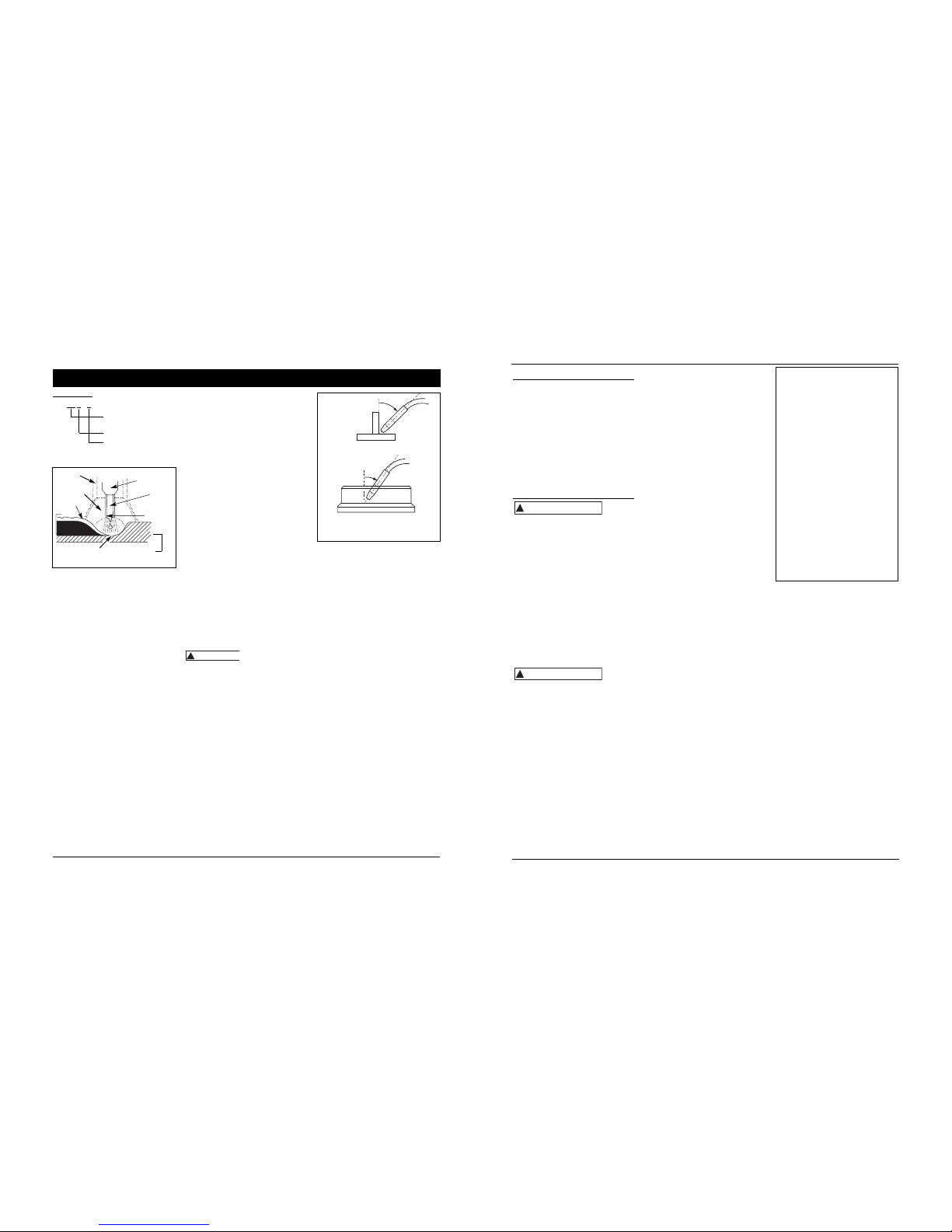
TECHNIQUE POUSSER VS TIRER
Le type et l’épaisseur de la pièce de
travail agissent sur la direction de la buse
du pistolet. Pour des matériaux minces,
(calibre 18 et plus) et tout aluminium, la
buse devrait être dirigée en avant de la
flaque de soudure et devrait pousser
la flaque à travers de l’objet de travail.
Pour de l’acier épais, la buse devrait
être dirigée dans la flaque de soudure
pour augmenter la pénétration de la
soudure. Ceci est la technique main-
arrière ou tirer (voir figure 14).
scorie. Le débris chaud et volant peut
causer des blessures aux personnes
dans l’endroit.
Après avoir complété la soudure,
attendre que les sections de soudage se
refroidissent. Une couche protectrice
appelée scorie couvre le cordon de
soudure et empêche la réaction du métal
fondu avec les polluants dans l’air. La
scorie peut être enlevée une fois que la
soudure s’est refroidie et n’est plus rouge.
Enlever la scorie avec un marteau à
buriner. Frapper la scorie légèrement
avec le marteau et la dégager du cordon
de soudure. Finir avec une brosse
métallique. Enlever la scorie avant
chacune des passes multiples.
POSITIONS DE SOUDAGE
Il y a quatre positions générales de
soudage : plate, horizontale, verticale et
aérienne. Le soudage dans une position
plate est la plus facile. La vitesse peut être
augmentée, le métal fondu coule moins,
une meilleure pénétration est possible et
le travail est moins fatiguant. Le soudage
est effectué avec le fil à un angle de
déplacement de 45º et un angle de travail
de 45º. Autres positions exigent autres
techniques telles que le tissage, passe
circulaire et le jogging. Un niveau de plus
grande compétence est exigé pour ces
soudures.
La soudure aérienne est la position plus
difficile et dangereuse. Le réglage de la
chaleur et la sélection du fil varient selon
la position.
Tout le travail devrait être effectué dans
la position plate si possible. Pour les
applications spécifiques, consulter un
manuel technique de soudage.
PASSES DE SOUDAGE
Quelques fois il est nécessaire d’utiliser
plus d’une passe pour remplir le joint. La
première passe est la passe de base, suivie
par la passe de remplissage et la passe de
finition. Si les pièces sont épaisses, il peut
être nécessaire de biseauter les bords qui
sont unis à un angle de 60º. Se rappeler
d'enlever la scorie avant chaque passe
pour le procédé FCAW.
SOUDURE D'ALUMINIUM
Toute la surface d'aluminium à souder
23 Fr
Figure 12 - Passes de soudures
Enduit
Matière de
remplissage
Base
POUSSER
TIRER
Figure 14
L’angle de travail est l’angle horizontal,
mesuré aux angles droits à la ligne de
soudage. Pour la plupart des
applications, un angle de déplacement
de 45º et un angle de travail de 45º sont
suffisants. Pour les usages spécifiques,
consulter un manuel de soudage à l’arc.
VITESSE DE FIL
La vitesse de fil est réglée par le bouton
sur le paneau supérieur. La vitesse doit
être “réglée” selon le taux auquel le fil
est fondu dans l’arc. Le réglage est une
des fonctions critiques du soudage
alimenté en fil. Le réglage devrait être
effectué sur un morceau de métal
d’essai qui est de même type et
d’épaisseur que celui qui doit être
soudé. Procéder avec la soudure avec
une main en “trainant” la buse du
pistolet à travers de la pièce d’essai en
réglant la vitesse avec l’autre main. Une
vitesse trop lente causera un
crachement et le fil se brûlera dans la
pointe de contact. Une vitesse trop
rapide peut aussi causer un bruit de
crachement et le fil s’enfoncera dans la
plaque avant de se fondre. Un bruit
constant de bourdonnement indique
que la vitesse de fil est réglée
correctement. Répéter le procédé de
réglage chaque fois qu’il y a un
changement de réglage de chaleur,
diamètre ou type de fil, type de matériel
ou épaisseur de l’objet de travail. Pour
l'aluminium, la vitesse du fil est
normalement réglée plus haute (gamme
de vitesses 7-9).
VITESSE DE DÉPLACEMENT
La vitesse de déplacement est la vitesse
à laquelle le chalumeau est dirigé le
long de la surface de soudage. Le
diamètre et le type de fil à soudage,
l’intensite, la position et l’épaisseur de
l’objet de travail ont tous un effet sur
la vitesse de déplacement et peuvent
avoir un effet sur la qualité de la
soudure (voir figure 11). Lorsque la
vitesse est trop rapide, le cordon est
étroit et les ondulations du cordon sont
pointues. Lorsque la vitesse est trop
lente, la soudure se tasse et le cordon
est haut et large. Pour l'aluminium, la
vitesse du fil est normalement réglée
plus haute.
ENLEVAGE DE SCORIE
(FIL FOURRÉ DE FLUX SEULEMENT)
Porter
des
lunettes protectrices approvées ANSI
(norme ANSI Z87.1) et des vêtements
protecteurs pendant l’enlevage de la
!
AVERTISSEMENT
Directives de soudage à arc (suite)
Figure 13 - Passes multiples
2. Turn welder off.
3. Verify surfaces of metals to be joined
are free from dirt, rust, paint, oil,
scale or other contaminants. These
contaminants make welding difficult
and cause poor welds.
All persons
operating this
equipment or in the area while
equipment is in use must wear
protective welding gear including:
welding shield with proper shade,
flame-resistant clothing, leather
welding gloves and full foot protection.
If heating, welding or
cutting galvanized, zinc
plated, lead, or cadmium
plated materials, refer to
the General Safety
Information Section for instructions.
Extremely toxic fumes are created when
these metals are heated.
4. Connect work clamp to workpiece or
workbench (if metal). Make sure
contact is secure. Avoid surfaces with
paint, varnish, corrosion or nonmetallic materials.
5. Rotate Wire Speed Control to setting
number 5 to start, then adjust as
needed after test.
6. Plug power cord into a proper
voltage receptacle with proper circuit
capacity (see circuit requirements on
front page).
!
WARNING
!
WARNING
Assembly (Continued)
3. Install one end of gas hose to fitting
on the top of the arc welder and other
end of hose to fitting on regulator
using hose clamps on each connection.
Make sure gas hose is not kinked or
twisted.
4. While standing opposite cylinder
outlet, slowly open cylinder valve.
Inspect for leaks in the connections.
5. Pull trigger on gun to allow gas to
flow. Adjust gas regulator to
maximum flow by rotating clockwise.
Release trigger.
6. Remember to close gas cylinder valve
when finished arc welding.
Welding Shield Assembly
1. Cut detachable handle away from
shield. Trim the excess plastic to
remove sharp edges (see Figure 7).
2. To attach the handle, place shield on
a flat surface and press handle into
place (see Figure 7).
3. Insert filter lens exactly as shown in
Figure 8.
NOTE: If you have never welded
before or have little experience, a
full-face helmet is recommended.
Both hands are needed to stabilize
and control the angle and arc length
of the torch.
Operation
1. Be sure to read,
understand and comply
with all precautions in
the General Safety
Information section. Be
sure to read entire
"Welding Guidelines" section before
using this equipment.
6
Wire Feed Arc Welder
7. Switch arc welder on to desired heat
setting per decal inside wire feed
compartment.
NOTE: These settings are general
guidelines only. Heat setting may vary
according to welding conditions and
materials.
8. Verify wire is extended 1/4” from
contact tip. If not, squeeze trigger to
feed additional wire, release trigger,
turn welder off, and cut wire to
proper length. Then, switch back on
to desired heat setting.
9. Position wire feed gun near workpiece,
lower welding helmet by nodding
head or positioning the hand shield,
and squeeze gun trigger. Adjust heat
setting and wire speed as needed.
10. When finished welding, turn welder
off and store properly.
Maintenance
Disconnect power
supply and turn
machine off before inspecting or
servicing any components. Keep wire
compartment cover closed at all times
unless wire needs to be changed.
BEFORE EVERY USE:
1. Check condition of arc welding cables
and immediately repair or replace any
cables with damaged insulation.
2. Check condition of power cord and
immediately repair or replace any
cord if damaged.
3. Inspect the condition of the gun tip
and nozzle. Remove any weld slag.
Replace gun tip or nozzle if damaged.
Do not operate this
arc welding machine
with cracked or missing insulation on arc
welding cables, wire feed gun or power
cord.
EVERY 3 MONTHS:
1. Replace any unreadable safety labels
on the welder.
2. Use compressed air to blow all dust
and lint from ventilation openings.
3. Clean wire groove on drive roller.
Remove wire from feed mechanism,
remove screws from drive roller
housing. Use a small wire brush to
clean drive roll. Replace if worn or
damaged
!
WARNING
!
WARNING
MANUAL
Fig. 6 - Hose and Regulator Hookup
Figure 7
Figure 8
WG2063, 58-8027-4
Page 7

Soudeuse à dévidage de fil-électrode
22 Fr
Directives de soudage à arc
Généralités
Cet appareil de soudure à arc peut
utiliser le procédé connu sous le nom de
soudage à arc avec fil fourré (Flux-Cored
Arc Welding FCAW) ou le procédé à
soudage à l’arc sous gaz avec fil plein
(Gas Metal Arc Welding GMAW). La
soudure doit être protégée (enrobée)
des contaminants dans l’air tandis qu'elle
est en fusion. Le procédé FCAW utilise
un fil tubulaire avec un enrobage à
l’intérieur. L’enrobage crée un gaz de
protection lorsqu'il est fondu. Le
procédé GMAW utilise un gaz inerte
pour protéger la soudure en fusion.
Quand le courant est produit par un
transformateur (soudeuse à arc) et passe
à travers du circuit à un fil de soudage,
un arc est produit entre le bout du fil à
soudage et l’objet de travail. Cet arc fond
le fil et l’objet. Le métal fondu du fil à
soudage s’écoule dans le cratère fondu
et produit une adhérence avec l’objet de
travail indiqué ci-dessous (figure 9).
Principes du soudage à l’arc
Les cinq techniques qui ont un effet sur
la qualité de la soudure sont : la sélection
du fil, le réglage de chaleur, l’angle de
soudure, la vitesse du fil et la vitesse de
déplacement. La compréhension de ces
méthodes est nécessaire afin d’atteindre
une soudure efficace.
RÉGLAGE DE CHALEUR
La chaleur correcte nécessite un
ajustement du soudeur à arc au réglage
exigé. La chaleur ou la tension est réglée
par un interrupteur sur le soudeur. Le
réglage de la chaleur utilisé dépend de la
taille (diamètre) et du type de fil, la
position de la soudure et l’épaisseur de
l’objet. Se référer aux spécifications
indiquées sur le soudeur. Il est
recommandé de vous pratiquer sur des
morceaux de métal afin d’ajuster les
réglages et de comparer les soudures
avec la figure 11.
TYPE ET TAILLE DE FILS
Le choix correct du fil comprend une
variété de facteurs tels que la position
de soudage, le matériel de l’objet de
travail, l’épaisseur et la condition de la
surface.
FIL FOURRÉ DE FLUX
E - 7 0 T- GS
AWS E71T-GS ou E71T-11 sont
recommandés pour ce soudeur.
FIL SOLIDE
ER - 70 S - 6
ER-70S6 est recommandé pour ce
soudeur.
ANGLE DE SOUDURE
L’angle de soudure est l’angle de la
buse pendant le soudage. L’utilisation
de l’angle correct assure la pénétration
et la formation du cordon de soudure
exigé. L’angle de soudure est très
important pour les positions de soudure
différentes afin de produire une bonne
soudure. L’angle de soudure comprend
deux positions : l’angle de déplacement
et l’angle de travail vertical. L’angle de
déplacement est l’angle situé dans la
ligne de la soudure et peut varier entre
5º et 45º selon les conditions de
soudage.
ANGLE DE DÉPLACEMENT
ANGLE DE SOUDURE
5º - 45º
5º - 45º
Figure – 10 - Angle de soudure
Chaleur,
vitesse de fil
et vitesse de
déplacement
ordinaires
Chaleur trop basse
Chaleur trop élevée
Vitesse de fil
trop rapide
Vitesse de fil trop lente
Vitesse de
déplacement trop
lente
Vitesse de
déplace-
ment trop
rapide
Métal
commun
Figure 11 - Apparence de la soudure
Rigidité de la soudure x
10 000 livres par pouce
carrés.
Positions de soudure
(0 pour plate ou
horizontale, 1 pour les
autres positions)
Fil fourré en flux tubulaire
Type de flux
Rigidité de la
soudure x
1000 lb/po
2
Fil solide
Composition du fil
Scorie
Fil
Flux (sans
gaz
seulement)
Objet de
travail
Gaz
protecteur
Pointe de
contact
Cratère
Buse
Figure 9 – Parties de soudage
Soudure
WIRE TYPE AND SIZE
The correct choice of wire type
involves a variety of factors, such as
welding position, workpiece material
type, thickness, and condition of
surface to be welded.
FLUX-CORE WIRE
E - 7 0 T- GS
Weld strength, times
10,000 pounds per
square inch
Welding positions (0
for flat or horizontal,
1 for any position)
Tubular flux-core wire
Flux-type
AWS E71T-GS or E71T-11 is
recommended for this welder.
7
Arc Welding Guidelines
WG2063, 58-8027-4
Supply Cable Replacement
1. Verify that arc welder is OFF and
power cord disconnected.
2. Remove arc welder side panel to
expose switches.
3. Disconnect the black power cord
wire connected to the switch
and the white cord wire from
the transformer windings.
4. Disconnect the green power
cord wire connected to arc
welder base.
5. Loosen the cord strain relief
screw(s) and pull cord out of
strain relief and wire post.
6. Install new cord in reverse order.
General
This arc welder can utilize the flux-core
arc welding (FCAW) process or the gas
metal arc welding (GMAW) process. The
weld must be protected (shielded) from
contaminants in the air while it is
molten. The FCAW process uses a tubular
wire with a flux material inside. The flux
creates a shielding gas when melted. The
GMAW process uses inert gas to shield
the weld while molten.
When current is produced by a
transformer (arc welder) and flows
through the circuit to the weld wire, an
arc is formed between the end of the
weld wire and the workpiece. This arc
melts the wire and the workpiece. The
melted metal of the weld wire flows into
the molten crater and forms a bond with
the workpiece as shown (Figure 8).
Arc Welding Basics
Five basic techniques affect weld quality.
These are: wire selection, heat setting,
weld angle, wire speed, and travel
speed. An understanding of these
techniques is necessary for effective arc
welding.
HEAT SETTING
The correct heat involves the adjustment
of the arc welder to the required setting.
Heat or voltage is regulated by a switch
on the arc welder. The heat setting used
depends on the size (diameter) and type
of wire, position of the weld, and the
thickness of the workpiece. Consult
specifications listed on the arc welder. It
is suggested that you practice with scrap
metal to adjust settings, and compare
welds with Figure 11.
Consumable and Wear Parts
The following parts require routine
maintenance:
• Wire feed drive roller
• Gun liner (replace if worn)
• Nozzle/contact tips
• Wire - This welder will accept either 4”
or 8” diameter spools. Flux-core wire
is susceptible to moisture and oxidizes
over time, so it is important to select a
spool size that will be used within
approximately 6 months.
CHANGING WIRE SIZES
This welder is setup for .035" (.9 mm)
wire. If a different wire size is used, the
wire feed drive roller and contact tip
may need changing. There are two
grooves in the drive roller. The small
groove is for .024" (.6 mm) wire and
the other is for .030 – .035" (.8 –.9 mm)
wire. Remove the roller cover and flip
the drive roller to choose the correct
groove (see parts breakdown). The
contact tip should also match the wire
diameter used. The tip diameter is
marked on the contact tip in inches or
millimeters.
Page 8
21 Fr
Fonctionnement (suite)
soudeur et couper le fil à la longueur
appropriée. Remettre l’appareil en
marche au réglage de chaleur voulu.
9. Placer le pistolet d’alimentation du fil
près du travail, abaisser le casque de
soudure en hochant la tête ou placer
le masque de soudage à main et
presser la gâchette. Ajuster le réglage
de chaleur et la vitesse du fil au
besoin.
10. À la fin de la soudure, éteindre le
soudeur et ranger correctement.
Entretien
Débran-
cher et
mettre la machine hors circuit avant de
vérifier ou de procéder à l’entretien de
n’importe quelle pièce détachée.
Toujours garder le couvercle du
compartiment de fil fermé sauf
pendant le changement du fil.
AVANT CHAQUE USAGE :
1. Vérifier la condition des câbles de
soudage à arc et réparer ou remplacer
immédiatement les câbles dont
l’isolation est endommagée.
2. Vérifier la condition du cordon
d’alimentation et le réparer ou le
remplacer immédiatement si
endommagé.
3. Inspecter la condition du bout du
pistolet et de la buse. Enlever la
scorie, si présente. Remplacer le bout
du pistolet ou la buse si endommagés.
Ne pas
utiliser
ce soudeur à arc si l’isolation sur les
câbles de soudage, le pistolet ou le
cordon d’alimentation est fendue ou
manquante.
CHAQUE TROIS MOIS :
1. Remplacer toutes étiquettes de
sécurité sur le soudeur qui ne sont
pas lisables.
2. Utiliser de l’air comprimé pour
souffler toute la poussière des
ouvertures de ventilation.
3. Nettoyer l’encoche de fil sur le
rouleau d’entraînement. Enlever le fil
du dispositif d’alimentation et les vis
du carter du rouleau d’entraînement.
Utiliser une petite brosse métallique
pour nettoyer le rouleau
d’entraînement. Remplacer si usé ou
endommagé.
!
AVERTISSEMENT
!
AVERTISSEMENT
WG2063, 58-8027-4
Pièces nondurables ou qui peuvent
s’user
Les pièces suivantes exigent de
l’entretien ordinaire :
• Rouleau d’entraînement
d’alimentation de fil
• Chemise du pistolet (remplacer si
usée)
• Buse/bouts de contact
• Fil – Ce soudeur acceptera les bobines
de diamètre 4 po ou 8 po (10,16 ou
20,32 cm). Le fil à âme en flux est
sensible à l’humidité et s’oxyde après
quelques temps. Il est important de
choisir une taille de bobine qui sera
utilisée dans une période de 6 mois.
CHANGEMENT DE TAILLE DE FILS
Ce soudeur est réglé pour le fil 0,035 po
(0,9 mm). Si une différente taille de fil
est utilisée, le rouleau d’entraînement et
la buse de contact auront peut-être
besoin d’être changés. Il y a deux
rainures dans le rouleau d’entraînement.
La petite rainure est pour le fil 0,024 po
(0,6 mm) et l’autre est pour le fil de
0,030–0,035 po (0,8–0,9 mm). Enlever le
couvercle du rouleau et tourner le
rouleau d’entraînement afin de choisir
la rainure correcte (voir la description de
pièces). La buse de contact devrait
correspondre au diamètre du fil utilisé.
Le diamètre de la buse est indiqué sur la
buse de contact en pouces ou en
millimètres.
Remplacement du câble
d’alimentation
1. Verifier que le soudeur à arc soit
hors circuit (OFF) et le cordon
d’alimentation soit débranché.
2. Retirer le panneau du côté
soudure pour exposer les
interrupteurs.
3. Débrancher le fil du cordon noir
branché à l’interrupteur et le fil
du cordon blanc aux
enroulements du transformateur.
4. Débrancher le fil du cordon vert
branché à la base du soudeur à
arc.
5. Desserrer la(les) vis du réducteur
de tension du cordon et sortir le
cordon du réducteur et de la
borne à fil.
6. Installer un nouveau cordon selon
l’ordre inverse.
Wire Feed Arc Welder
8
Arc Welding Guidelines (Continued)
SOLID WIRE
ER - 70 S - 6
Weld strength, times
1,000 PSI
Solid wire
Wire composition
ER-70S6 is recommended for this
welder.
WELD ANGLE
Weld angle is the angle at which the
nozzle is held during the welding
process. Using the correct angle ensures
proper penetration and bead formation.
As different welding positions and weld
joints become necessary, nozzle angle
becomes an increasingly important
factor in obtaining a satisfactory weld.
Weld angle involves two positions: travel
angle and work angle.
Travel angle is the vertical angle in the
line of welding and may vary from 5º to
45º, depending on welding conditions.
Work angle is the horizontal angle,
measured at right angles to the line of
welding. For most applications, a 45º
travel angle and 45º work angle is
sufficient. For specific applications,
consult an arc welding handbook.
WIRE SPEED
The wire speed is controlled by the
knob on the front panel. The speed
needs to be “tuned” to the rate at
which the wire is being melted in the
arc. Tuning is one of the most critical
functions of wire feed welding. Tuning
should be performed on a scrap piece
that is of metal the same type and
thickness as the actual workpiece.
Begin welding with one hand
“dragging” the gun nozzle across the
scrap piece while adjusting the wire
speed with the other hand. Too slow of
speed will cause sputtering and the
wire will burn up into the contact tip.
Too fast a speed will also cause a
sputtering sound and the wire will push
into the plate before melting. A
smooth buzzing sound indicates the
wire speed is properly tuned. Repeat
the tuning procedure each time there is
a change in heat setting, wire diameter
or type, or workpiece material type or
thickness. For aluminum, wire speed is
typically set higher (7–9 speed range).
TRAVEL SPEED
The travel speed is the rate at which the
torch is moved across the weld area.
Factors such as diameter and type of weld
wire, amperage, position, and workpiece
material thickness all affect the speed of
travel necessary for completing a good
weld (see Fig. 11). When the speed is too
fast, the bead is narrow and bead ripples
are pointed. When the speed is too slow,
the weld metal piles up and the bead is
high and wide. For aluminum, travel
speed is typically faster.
SLAG REMOVAL
(FLUX-CORE WIRE ONLY)
Wear ANSI
approved safety
glasses (ANSI Standard Z87.1) and
protective clothing when removing
slag. Hot, flying debris can cause
personal injury to anyone in the area.
After completing the weld, wait for the
welded sections to cool. A protective
coating called slag now covers the weld
bead which prevents contaminants in
the air from reacting with the molten
metal. Once the weld cools to the point
that it is no longer glowing red, the
slag can be removed. Removal is done
with a chipping hammer. Lightly tap
the slag with the hammer and break it
loose from the weld bead. The final
clean-up is done with a wire brush.
When making multiple weld passes,
remove the slag before each pass.
WELDING POSITIONS
Four basic welding positions can be used :
flat, horizontal, vertical, and overhead.
Welding in the flat position is easier than
!
WARNING
any of the others because welding speed
can be increased, the molten metal has less
tendency to run, greater penetration, and
the work is less fatiguing. Welding is
performed with the wire at a 45º travel
angle and 45º work angle.
Other positions require different
techniques such as a weaving pass,
circular pass, and jogging. A higher skill
level is required to complete these welds.
Overhead welding is the least desirable
position as it is the most difficult and
dangerous. Heat setting and wire selection
will vary depending upon the position.
All work should be performed in the
flat position, if possible. For specific
applications, consult an arc welding
technical manual.
WELD PASSES
Sometimes more then one pass is
necessary to fill the joint. The root pass
is first, followed by filler passes and the
cover pass. If the pieces are thick, it may
be necessary to bevel the edges that
are joined at a 60º angle. Remember to
remove the slag before each pass for
the FCAW process.
ALUMINUM WELDING
Any aluminum surface to be welded,
must be cleaned thoroughly with a
stainless steel brush to eliminate any
oxidation on the weld and grounding
surface. 100% Argon shielding gas must
be used when welding aluminum. If
TRAVEL ANGLE
WORK ANGLE
5º - 45º
5º - 45º
Fig. 10 - Weld Angle
Slag
Weld
Wire
Flux
(Gasless
only)
Workpiece
Shielding
Gas
Contact
Tip
Crater
Nozzle
Fig. 9 - Weld Components
Page 9

Montage (suite)
argon. Fixer la bouteille sur votre
soudeuse ou sur un autre support pour
éviter le basculage de la bouteille.
RÉGULATEUR
Un régulateur réglable sans jauge est
fourni avec ce soudeur à arc. Le
régulateur fournit une pression et un débit
constant de gaz pendant le soudage à arc .
Chaque régulateur est conçu pour
l’utilisation avec un type ou mélange de gaz
particulier. L’argon et les mélanges d’argon
utilisent le même type de filets. 100 % gaz
carbonique utilise un différent type de
filets. Des adaptateurs sont disponibles chez
votre fournisseur de gaz de soudure.
PROCÉDURE DE RACCORDEMENT DE
TUYAU ET DE RÉGULATEUR
Les bouteilles de gaz sont sous haute
pression. Diriger l’orifice
d’échappement à l’écart de soi-même
ou d’autres personnes avant de l’ouvrir.
1. Avec la bouteille bien installée, se
tenir au bord opposé de l’orifice
d’échappement, enlever le capuchon
de la bouteille et ouvrir la soupape un
peu en tournant au sens contraire des
aiguilles d’une montre. Quand le gaz
sort de la bouteille, fermer la soupape
en tournant au sens des aiguilles
d’une montre. Ceci sert à purger la
poussière qui peut s’accumuler autour
du siège de la soupape.
2. Installer le régulateur sur le robinet de
la bouteille. Bien resserrer l'écrou de la
tige sur la soupape de gaz.
3. Installer un bout du tuyau de gaz au
raccord situé sur le dessus du soudeur à
arc et l’autre bout du tuyau au raccord
du régulateur en utilisant des colliers de
serrage sur chaque raccordement.
S’assurer que le tuyau ne soit pas tortillé.
4. Se positionner encore au bord
opposé de l’orifice de sortie de la
bouteille et ouvrir la soupape
lentement. Inspecter pour des fuites
dans l’endroit des raccordements.
5. Tirer la gâchette du pistolet pour
laisser le gaz couler. Ajuster le
régulateur de gaz au débit maximum
en tournant dans le sens des aiguilles
d'une montre. Dégager la gâchette.
6. N’oubliez pas de fermer la soupape
de gaz lorsque vous avez fini de
souder à l'arc.
Montage du masque de soudeur
1. Éloigner la poignée amovible du
!
AVERTISSEMENT
masque. Tailler le surplus de plastique
pour retirer les bords tranchants (voir
la figure 7).
2. Pour fixer le manche, placer le
masque à main sur une surface
nivelée et appuyer sur le manche
jusqu’à ce qu’il soit en place (voir
figure 7).
3. Insérer la lentille du filtre exactement
tel qu’indiqué à la figure 8.
REMARQUE : Si vous n’avez jamais
utilisé un soudeur ou si vous avez peu
d’expérience, il est recommandé que
vous utilisez un masque qui couvre
complètement votre visage. Les deux
mains sont nécessaires pour stabiliser et
contrôler l’angle et la longeur de l’arc
de l’électrode.
Fonctionnement
1. Lire, comprendre et suivre
toutes les précautions dans
la section Généralités sur la
sécurité. Lire la section
entière de Directives de
soudage avant d’utiliser l’équipement.
2. Mettre le soudeur hors circuit.
3. Vérifier que les surfaces du métal
soient libres de saleté, rouille,
peinture, huile, écailles ou autres
polluants avant de les souder
ensemble. Ces polluants rendent la
20 Fr
Soudeuse à dévidage de fil-électrode
soudure difficile et peuvent causer de
mauvaises soudures.
Toutes
personnes
utilisant cet équipement ou qui sont
dans l’endroit pendant l’utilisation de
l’équipement doivent porter des
vêtements de soudage protecteurs y
compris: masque de soudeur avec
lentille correcte, vêtements
incombustibles, gants de soudeur en
cuir et protection complète pour les
pieds.
Pour le chauffage, soudage
ou coupage des matériaux
galvanisés, plaques en zinc,
plomb ou en cadmium, se référer à la
section Généralités sur la sécurité pour
plus d’instructions. Des vapeurs
extrêmement toxiques sont produites
pendant le chauffage de ces métaux.
4. Raccorder la pince de soudeur à
l’objet de travail ou à l’établi (si en
métal). S’assurer que le contact soit
sûr et nonpollué par la peinture, le
vernis, la corrosion ou autres
matériaux nonmétalliques.
5. Tourner la commande de vitesse de fil
jusqu’au numéro 5 pour commencer,
puis ajuster au besoin après le test.
6. Brancher le cordon d’alimentation
dans une prise de courant à la bonne
tension et à la bonne capacité de
circuit (voir les exigences de circuit à la
page avant).
7. Allumer le soudeur à arc au réglage
de chaleur voulu selon le décalque à
l’intérieur du compartiment
d'alimentation du fil.
REMARQUE : Ces réglages sont établis
comme guides généraux. Les réglages de
chaleur sont variables selon les conditions
de soudage et le matériel utilisé.
8. Vérifier que le fil sort de 0,635 cm
(1/4 po) de la pointe de contact. Sinon,
presser la gâchette pour ajouter du
fil, dégager la gâchette, éteindre le
!
AVERTISSEMENT
!
AVERTISSEMENT
Figure 7
Figure 8
Figure 6 – Raccordement de tuyau et de
régulateur
MANUAL
9
WG2063, 58-8027-4
100% Argon is not used, metal
penetration is unlikely. When welding
aluminum, it is recommended (Kit
WT2531) that a PTFE wire liner,
smooth-groove drive roller and
aluminum contact tips be used.
PUSH VS PULL TECHNIQUE
The type and thickness of the workpiece
dictates which way to point the gun
nozzle. For thin materials (18–gauge and
up) and all aluminum, the nozzle should
point out in front of the weld puddle
and push the puddle across the
workpiece. For thicker steel, the nozzle
should point into the puddle to increase
weld penetration. This is called backhand
or pull technique (See Figure 14).
Arc Welding Guidelines (Continued)
Fig. 12 - Weld Passes
Cover
Filler
Root
Fig. 13 - Multiple Weld Passes
PUSH
PULL
Fig. 14
Normal Heat,
Wire Speed,
Travel Speed
Heat Too Low
Heat Too High
Wire Speed
Too Fast
Wire Speed Too Slow
Travel Speed
Too Slow
Travel Speed
Too Fast
Base
Metal
Fig. 11 - Weld Appearance
Page 10

Montage (suite)
9. Glisser avec soin la pointe de contact
sur le fil et visser la pointe sur
l'extrémité du chalumeau. Installer
la buse en tournant dans le sens des
aiguilles d'une montre (voir figure
4). Couper le fil à environ 1/4 po
(0,635 cm) de l'extrémité de la buse.
FACTEUR D’UTILISATION/PROTECTION
CONTRE LES SURCHARGES THERMIQUES
Le facteur d’utilisation de soudage est
le pourcentage du temps de soudage à
l'arc actuel qui peut se faire dans un
intervalle de dix minutes. Par exemple,
à un cycle de service de 20 %, la
soudure réelle se fait pendant deux
minutes, puis le soudeur doit refroidir
pendant huit minutes.
Les pièces détachées internes de ce
soudeur sont protégées contre le
surchauffage avec un interrupteur
automatique thermique. Une lampe
jaune sur le panneau d’avant est
allumée si vous dépassez le facteur
d’utilisation. Continuer avec le soudage
quand la lampe n’est pas allumée.
COMMANDE DE POLARITÉ
Un fil MIG exige une polarité
électrique d'électrode positive. Un fil à
âme en flux exige une polarité
électrique d'électrode négative. Le
soudeur est réglé en usine pour un fil
de soudure fourré.
Pour changer la polarité
(voir la figure
5a)
REMARQUE : La flèche sur le couvercle
de polarité pointe vers le réglage de
polarité actuel.
OUTILS NÉCESSAIRES : Tournevis et
clé à douilles de 10 mm.
Préparation pour le gaz
protecteur
La
manipulation et l’entretien incorrects des
bouteilles de gaz comprimé et des
régulateurs peuvent résulter en
blessures graves ou perte de vie!
Toujours fixer les bouteilles de gaz au
nécessaire de support du réservoir, à un
mur ou autre support stationnaire afin
d’éviter le basculage. Lire, comprendre
et suivre tous les avertissements et
instructions de sécurité pour le gaz
comprimé et l’équipement.
REMARQUE : Le gaz n’est pas
nécessaire si le fil fourré de flux est
utilisé.
TYPES DE GAZ
Il y a trois types de gaz populaires pour
le soudage à l’arc avec gaz : 100 %
argon, un mélange de 75 % argon et
25 % gaz carbonique (C25) ou 100 %
gaz carbonique.
Utiliser
SEULEMENT le type de gaz recommandé
pour votre soudeur. Utiliser SEULEMENT
un gaz inerte ininflammable. Le nonrespect de ces indications mènera à une
situation très dangereuse.
REMARQUE : Le dioxyde de carbone à
100 % n'est pas recommandé à cause de
boudin de soudure insatisfaisant.
Pour le soudage d'acier générale un
mélange 75/25 est recommandé. Pour le
soudage d’aluminium, utiliser 100 %
!
DANGER
!
DANGER
1. Débrancher le cordon
d'alimentation de la prise.
2. Retirer la vis du couvercle et le
couvercle de polarité.
3. Retirer quatre écrous des goujons
de polarité.
4. Retirer la barre-omnibus de polarité
et tourner de 90°. Réinsérer en
alignant la rainure avec la bonne
nervure sur la boîte de polarité. La
nervure droite supérieure marque
la position MIG tandis que la
nervure droite infèrieure marque la
position d'âme en flux (voir la
figure 5b).
5. Réinstaller quatre écrous et bien
resserrer.
6. Réinstaller le couvercle de polarité
et la vis du couvercle.
7. S'assurer que la flèche sur le
couvercle de polarité pointe au
réglage voulu.
19 Fr
Figure 4 – Buse du
chalumeau
Pointe de contact
Buse
Chalumeau diffuseur
Marques de pointe de contact
Marque Taille de fil
0,6 mm 0,024 po
0,8 mm 0,030 po
0,9 mm 0,035 po
WG2063, 58-8027-4
Figure 5a
Boîte de
polarité
Nervure
de flux
Barre-omnibus
de polarité
Écrous
Vis du
couvercle
Couvercle
de
polarité
Rainure
Goujons de polarité
Nervure MIG
Figure 5b
Position MIG
Position flux
Position droite
supérieure-nervure
MIG
Position droite
inférieure-nervure flux
10
Wire Feed Arc Welder
Troubleshooting Chart - Wire Feed Arc Welder
Symptom Possible Cause(s) Corrective Action
Toll Free Helpline: 1-866-220-2097
Troubleshooting Chart - Welds
Symptom Possible Cause(s) Corrective Action
1. Duty-cycle exceeded.
2. Poor work clamp connection.
3. Defective power switch.
4. Blown breaker or fuse.
1. Wrong size gun tip.
2. Gun liner clogged or
damaged.
3. Gun tip clogged or damaged.
4. Feed roller worn.
5. Not enough tension.
1. Slag inside gun nozzle.
2. Insulation ring melted/expired.
1. Poor contact.
2. Using an extension cord with
excessive length.
1. Wire jammed.
2. Out of wire.
3. Not enough tension.
4. Wire liner worn.
5. Wire disconnected internally.
6. Contact tip clogged.
1. Wire speed too slow.
2. Travel speed too slow or heat
is too high.
1. Wire speed setting.
2. Contact tip size too large.
3. Polarity set incorrectly.
4. Drive roller slipping.
5. Gas bottle empty.
1. Allow welder to cool until lamp goes out.
2. Be sure all connections are secure, and attaching surface is
clean.
3. Replace switch.
4. Reduce circuit load, reset breaker or replace fuse.
1. Use proper size gun tip.
2. Clean or replace gun liner.
3. Clean or replace gun tip.
4. Replace.
5. Tighten tensioning screw.
1. Clean slag from gun nozzle.
2. Replace nozzle.
1. Be sure all connections are secure, and attaching surface is
clean.
2. Never use an extension cord longer than 20’.
1. Reload wire.
2. Replace wire spool.
3. Tighten tensioning screws, if wire is slipping.
4. Replace liner.
5. Call toll free helpline.
6. Replace contact tip.
1. Run speed in 7–10 range.
2. Increase the travel speed or reduce heat settings.
1. Tune in correct setting (1–5 mild steel; 5–10 aluminum).
2. Replace contact tip.
3. Reverse polarity.
4. Increase tension.
5. Replace gas bottle.
No output.
Wire tangles at drive roller.
Gun nozzle arcs to work
surface.
Work clamp and/or cable
gets hot.
Wire does not feed.
(Aluminum) Wire burns back
into tip or (Aluminum) Metal
bubbles or burns through.
Weld pops and sputters.
Bead is intermittently
too thin.
Bead is intermittently
too thick.
Ragged depressions at
edge of weld.
Weld bead does not
penetrate base metal.
Wire sputters and
sticks.
1. Inconsistent travel speed.
2. Output heat setting too low.
1. Slow and/or inconsistent travel speed.
2. Output heat setting too high.
1. Travel speed too fast.
2. Wire speed too fast.
3. Output heat setting too high.
1. Inconsistent travel speed.
2. Output heat setting too low.
3. No or low shielding gas.
4. Wrong shielding gas (aluminum).
5. Extension cord is too long.
6. (Aluminum) Possible oxide buid-up on
surface.
1. Damp wire.
2. Wire speed too fast.
3. Wrong type of wire.
4. No or low shielding gas.
1. Decrease and maintain constant travel speed.
2. Increase output heat setting.
1. Increase and maintain travel speed.
2. Reduce output heat setting.
1. Decrease travel speed.
2. Decrease wire speed.
3. Reduce output heat setting.
1. Decrease and maintain constant travel speed.
2. Increase output heat setting.
3. Use gas for MIG process or refill bottle.
4. Use only 100% Argon gas.
5. Never use an extension cord longer than 20’.
6. Clean surface thoroughly with a stainless steel brush only.
1. Use dry wire and store in dry location.
2. Reduce wire speed.
3. Use flux-core wire when not using gas.
4. Use gas for MIG process or refill bottle.
Page 11

INSTALLATION DE FILS
REMARQUE : Avant d’installer le fil à
soudage, s’assurer que :
a. Le diamètre du fil de soudure
s'agence à la rainure du rouleau
entraîneur sur le mécanisme
d'alimentation du fil (voir figure
3). Le rouleau entraîneur est
marqué en tailles métriques :
0,6 mm, 0,8 mm, 0,9 mm.
b. Le fil s'agence à la pointe de
contact sur l'extrémité du pistolet
(voir figure 4).
Des articles qui ne se correspondent pas
peuvent causer le patinage et le
coinçage du fil.
REMARQUE : Toujours maintenir le
contrôle de l'extrémité libre du fil de
soudure pour éviter le débobinage.
1. Vérifier que le modèle soit hors
circuit (OFF) et ouvrir le panneau sur
le soudeur afin d’exposer le
mécanisme d’alimentation de fil
2. Enlever le blocage de broche en
appuyant et tournant 1/4 de tour au
Soudeuse à dévidage de fil-électrode
Installation
ENDROIT
La sélection de l’endroit correct peut
améliorer de façon spectaculaire le
rendement, la fiabilité et la durée du
soudeur à l’arc.
Pour un meilleur résultat, utiliser le
soudeur dans un endroit propre et
sec. La poussière et la saleté dans le
soudeur conservent l’humidité et
augmentent l’usure des pièces
mobiles.
Placer le soudeur dans un endroit
avec au moins douze pouces
(30,5 cm) d’espace pour la
ventilation en avant et en arrière du
modèle. Garder cet espace libre
d’obstructions.
Ranger le fil de soudage dans un
endroit propre et sec à faible
humidité pour éviter l'oxydation.
Utiliser une prise de courant mise à
la terre correctement pour le
soudeur et s’assurer que le soudeur
soit le seul appareil de charge sur le
circuit d’alimentation. Se référer au
tableau sur la page 1 pour la
capacité correcte du circuit.
L’utilisation d’un cordon prolongateur
n’est pas recommandée pour la
soudeuse. Une perte de tension dans
le cordon prolongateur peut diminuer
de façon spectaculaire le rendement
du soudeur.
Montage
ASSEMBLAGE DU DISPOSITIF DE
RETENUE DE LA BOUTEILLE
Fixer le dispositif de retenue de la
bouteille au soudeur tel qu'illustré
(fig. 2).
sens inverse des aiguilles d’une
montre. Ensuite enlever le ressort et
le capuchon de broche.
3. Installer la bobine sur la broche afin
que le fil puisse sortir de la bobine
par le bas. Ne pas couper le fil tout
de suite. Installer le capuchon de
broche, le ressort et le blocage de
broche en tournant le bouton 1/4 de
tour au sens des aiguilles d’une
montre.
4. Tenir le fil et couper le fil du bout de
la bobine. Ne pas permettre que le
fil se démêle. S’assurer que le bout
du fil soit droit et sans ébarbures.
5. Rabattre la vis de tensionnement sur
le mécanisme d'entraînement. Ceci
permet l’acheminement initial du fil
dans la doublure du pistolet à main.
6. Soulever le bras pivotant. Faire passer
le fil dans le tube d'alimentation, dans
le rouleau et dans la gaine de fil.
Rabattre le bras pivotant. Tirer sur la vis
de tension de fil. Régler la tension
(éviter de trop serrer). Fermer le
panneau latéral.
7. Enlever la buse en la tournant au sens
contraire des aiguilles d’une montre.
Ensuite desserrer la pointe de contact
du bout du chalumeau de soudeur
(voir figure 4). Brancher le soudeur
dans une prise de courant
convenable.
8. Mettre le soudeur en marche et
régler la vitesse du fil à 10. Activer la
gâchette du pistolet jusqu'à ce que le
fil dépasse l'extrémité du chalumeau
de 1 1/2 po. Mettre le soudeur hors
circuit.
18 Fr
Figure 2 - Assemblage du dispositif de
retenue de la bouteille
Broche
Bobine de fil
de soudure
Capuchon de broche
Ressort
Blocage de broche
Vis de tension
Tube guide d'alimentation
Bras pivotant
Tablier
d’entraînement
Support
de
rouleau
Rouleau
Figure 3 - Acheminement du fil de soudure
11
WG2063, 58-8027-4
1 Torch Assembly & Hose (MIG) WC403660AV 1
2 Contact Tip – 0.035” (0.9 mm) WT501400AV 1
Optional Contact Tip – 0.024” (0.6 mm)
4 Pack WT501200AJ †
Optional Contact Tip – 0.030” (0.8 mm)
4 Pack WT501300AJ †
Optional Contact Tip – 0.035” (0.9 mm)
4 Pack WT501400AJ †
3 Nozzle WT502100AV 1
4 Drive Roller WC500805AV 1
5 Drive Deck Assembly WC500800AJ 1
6 Spindle & Grille WC707018AV 1
7 Spool Retainer WC707024AV 1
8 Spool Retainer Spring WC707026AV 1
9 Spool Retainer Ring WC707023AV 1
10 Flux Weld Wire – 0.030” (0.8 mm)
2 lb. Roll (E71T-GS) WE200001AV †
Flux Weld Wire – 0.030” (0.8 mm)
10 lb. Roll (E71T-GS) WE201000AV †
Flux Weld Wire – 0.035” (0.9 mm)
2 lb. Roll (E71T-GS) WE200501AV †
Flux Weld Wire – 0.035” (0.9 mm)
10 lb. Roll (E71T-GS) WE201500AV †
MIG Weld Wire – 0.024” (0.6 mm)
2 lb. Roll (ER70S6) WE300001AV †
MIG Weld Wire – 0.024” (0.6 mm)
11 lb. Roll (ER70S6) WE301500AV †
Ref. Part
No. Description Number Qty
MIG Weld Wire – 0.030” (0.8 mm)
2 lb. Roll (ER70S6) WE300501AV †
MIG Weld Wire – 0.030” (0.8 mm)
11 lb. Roll (ER70S6) WE302000AV †
MIG Weld Wire – 0.035” (0.9 mm)
2 lb. Roll (ER70S6) WE301001AV †
MIG Weld Wire – 0.035” (0.9 mm)
11 lb. Roll (ER70S6) WE302500AV †
MIG Weld Wire – 0.030” (0.8 mm)
1 lb. Aluminum (ER5356) WE303001AV †
11 Bottle Retainer with 4 Screws WC302600AJ 1
12 Barbed Hose Fitting (External) WC403900AV 1
Quick Connect Fitting (Internal) WC403901AV 1
13 Gas Hose – 22” WC403902AV 1
14 Hose Clamp WC403903AV 2
15 Regulator WC802500AV 1
16 Hand Shield (Lens not included) WC801700AV 1
17 Shaded Lens (For Hand Shield) WC801100AV 1
18 Chipping Hammer-Brush WC803400AV 1
19 Safety Decal DK688509AV 1
20 Polarity Bus Bar Kit WC403128AV 1
Not Shown
† Optional Accessory
Ref. Part
No. Description Number Qty
3
4
1
8
9
2
11
10
7
12
6
5
Fig. 15 – Replacement Parts
Please provide following information:
- Model number
- Serial number (if any)
- Part description and number as
shown in parts list
Replacement Parts List
For replacement parts or
technical assistance, call
1-866-220-2097
Fiche technique :
Puissance : 115 V, 15 ou 20 A
Épaisseur de métal : calibre 24 à
3/16 po
Facteur de marche : 20% à 70 A
Courant de sortie : 40 à 70 A
Fil utilisé : soudage sous gaz
inerte de 0,024,
0,030 po ou âme
en flux de 0,030,
0,035 po
Page 12

Généralités sur la
sécurité (suite)
n’importe quel travail de métal. Prenez
toutes précautions indiquées dans ce
manuel afin de réduire la possibilité de
brûlures de peau ou de vêtements.
S’assurer que toutes personnes dans
l’endroit de soudage soient protégées
contre la chaleur, les étincelles et les
rayons ultraviolets. Utiliser des écrans
de visage additionnels et des écrans
coupe-feu si nécessaire.
Ne jamais toucher les objets de travail
avant qu’ils soient complètement
refroidis.
La chaleur et les étincelles
qui sont produites pendant le
soudage à l’arc électrique et
autres travaux de métal peuvent
allumer les matériaux inflammables et
explosifs! Prenez toutes les précautions
indiquées dans ce manuel afin de
réduire la possibilité de flammes et
d’explosions.
Enlever tous les matériaux
inflammables à moins de 35 pieds
(10,7 m) de l’arc de soudage. Si
l’enlevage n’est pas possible, bien
couvrir les matériaux inflammables
avec des couvertures incombustibles.
Ne pas utiliser un soudeur à l’arc
électrique dans les endroits qui
contiennent des vapeurs
inflammables ou explosives.
Prenez précaution pour assurer que
les étincelles volantes et la chaleur
ne produisent pas de flammes dans
des endroits cachés, fentes, etc.
Risque
d’incendie! Ne pas souder les récipients ni les
tuyaux qui contiennent ou qui ont
contenu des matériaux inflammables
ou combustibles gazeux ou liquides.
Le soudage à l’arc des
bouteilles ou des récipients
fermés tels que les réservoirs
ou bidons peuvent causer une
explosion s’ils ne sont pas bien
ventilés! Vérifier qu’il y a un trou de
ventilation suffisant dans n’importe
quel récipient ou bouteille afin de
permettre la ventilation des gaz
pendant l’expansion.
!
AVERTISSEMENT
!
AVERTISSEMENT
!
AVERTISSEMENT
font partie du procédé de soudage, il est
nécessaire de les respecter.
Protéger les bouteilles de gaz
comprimé contre la chaleur excessive,
les chocs mécaniques et les arcs.
Installer et fixer les bouteilles dans
une position verticale en utilisant une
chaîne sur un support stationnaire ou
un support de bouteille afin d’éviter
le renversement ou le basculage.
Garder les bouteilles à l’écart du
soudage ou autres circuits électriques.
Ne jamais permettre que l’électrode
de soudage touche une bouteille.
Utiliser seulement les bouteilles
de gaz correctes, régulateurs,
tuyaux et raccords conçus pour
votre application et les tenir en
bon état de marche.
Tourner le visage à l’écart de la
soupape d’échappement en ouvrant
la soupape de la bouteille.
Garder le capuchon protecteur en
place sur la soupape sauf si la
bouteille est soi en service ou
branchée pour le service.
Lire et suivre les instructions pour les
bouteilles de gaz et autre
équipement, ainsi que la publication
CGA, P-1 indiquée dans les Normes
de sécurité.
Ne jamais
utiliser
les gaz inflammables avec les soudeurs
MIG. Seuls les gaz inertes ou
ininflammables tels que le bioxyde de
carbone, l’argon, l'hélium ou un
mélange d’un ou plus de ces gaz sont
convenables pour le soudage MIG.
Ne jamais
soulever
les bouteilles par leurs soupapes,
capuchons ni avec les chaînes ou élingues.
NORMES DE SÉCURITÉ ADDITIONNELLES
Normes ANSI Standard Z49.1 de la Société
American Welding Society.
Manipulation sûre des bouteilles de gaz
comprimé
Brochure CGA P-1, de l’Association
Compressed Gas Association.
Code pour la sécurité concernant le
soudage et le coupage
Norme CSA W117.2, de l’Association Canadian
Standards Association
Procédés de coupage et soudage
Norme NFPA 51B, le l’Association National Fire
Protection Association
Règlements professionnels et
d’éducation de sécurité pour la
protection des yeux et du visage
Norme ANSI Z87.1, de l’Institut American
National Standards Institute
!
AVERTISSEMENT
!
DANGER
17 Fr
Ne pas inspirer les vapeurs
qui sont produites par le
soudage à l’arc. Ces vapeurs
sont dangereuses. Utiliser un
respirateur fourni d’air si l’endroit de
soudage n’est pas bien ventilé.
Garder la tête et le visage hors des
vapeurs de soudage.
Des vapeurs extrêmement toxiques
sont produites pendant le chauffage
des métaux galvanisés, plaqués de
cadmium ou des métaux qui
contiennent le zinc, le mercure, ou le
beryllium. Compléter les précautions
suivantes avant d’exécuter le soudage
à l’arc électrique sur ces métaux :
a. Enlever l’enduit du métal commun.
b. S’assurer que l’endroit de soudage
soit bien ventilé.
c. Utiliser un respirateur fourni d’air.
Le champ électromagnétique
qui est produit pendant le
soudage à l’arc peut causer de
l’interférence avec le fonctionnement de
plusieurs appareils électriques tels que
les pacemakers cardiaques. Toutes
personnes utilisant ces appareils doivent
consulter leur médecin avant d’exécuter
le soudage à l’arc électrique.
Router le pistolet à fil et les câbles
ensembles et les fixer avec du ruban
adhésif si possible.
Ne jamais envelopper les câbles de
soudage à l’arc autour du corps.
Toujours situer le pistolet à fil et les
conducteurs de service sur le même
côté du corps.
L’exposition aux champs
électromagnétiques peut avoir
autres réactions inconnues
concernant la santé.
Avant de
laisser
l’endroit, s’assurer que l’endroit de
soudage est en état sûr et sans risques
(étincelles, flammes, métal chauffé au
rouge ou scorie). S’assurer que
l’équipement soit hors circuit et que
l’excès de fil soit taillé. S’assurer que
les câbles soient roulés (sans serrer) et
hors du chemin. S’assurer que tout
métal et scorie soient refroidis.
Les bouteilles peuvent
exploser si endommagées. Les
bouteilles de gaz contiennent
du gaz sous haute pression. Si
endommagée, une bouteille peut
exploser. Puisque les bouteilles de gaz
!
DANGER
!
AVERTISSEMENT
!
AVERTISSEMENT
!
AVERTISSEMENT
WG2063, 58-8027-4
12
Wire Feed Arc Welder
AC or Alternating Current: electric
current that reverses direction
periodically. Sixty cycle current travels
in both directions sixty times per
second.
Arc Length: the distance from the
end of the electrode to the point
where the arc makes contact with the
work surface.
Base Metal: the material to be
welded.
Butt Joint: a joint between two
members aligned approximately in the
same plane.
Crater: a pool, or pocket, that is
formed as the arc comes in contact
with the base metal.
DC or Direct Current: electric current
which flows only in one direction. The
polarity (+ or -) determines which
direction the current is flowing.
DC Reverse Polarity: occurs when
the electrode holder is connected to
the positive pole of the welding
machine. Reverse Polarity directs more
heat into melting the electrode rather
than the workpiece. It is used on
thinner material.
DC Straight Polarity: occurs when
the electrode holder is connected to
the negative pole of the welding
machine. With straight polarity more
heat is directed to the workpiece for
better penetration on thicker material.
Electrode: a coated metal wire having
approximately the same composition
as the material being welded.
Fillet Weld: approximately a triangle
in cross-section, joining two surfaces at
right angles to each other in a lap, T or
corner joint.
Flux: a coating, when heated, that
produces a shielding gas around the
welding area. This gas protects the
parent and filler metals from
impurities in the air.
Flux-Cored Arc Welding (FCAW):
also called Gasless, is a welding process
used with a wire feed arc welder. The
weld wire is tubular with flux material
contained inside for shielding.
Gas Metal Arc Welding (GMAW):
also called MIG, is a welding process
used with a wire feed arc welder. The
wire is solid and an inert gas is used for
shielding.
Lap Joint: a joint between two
overlapping members in parallel
planes.
Open Circuit Voltage (OCV): the
voltage between the electrode and the
work clamp of the welding machine
when no current is flowing (not
welding). The OCV determines how
quickly the arc is struck.
Overlap: occurs when the amperage is
set too low. In this instance, the
molten metal falls from the electrode
without actually fusing into the base
metal.
Porosity: gas pockets, or cavities,
formed during weld solidification.
They weaken the weld.
Penetration: the depth into the
workpiece that has been heat affected
by the arc during the welding process.
A good weld achieves 100%
penetration meaning that the entire
thickness of the workpiece has been
heated and resolidified. The heated
area should be easily seen on the
opposite side of the weld.
Shielded Metal Arc Welding
(SMAW): also called Stick, is a welding
process with uses a consumable
electrode to support the arc. Shielding
is achieved by the melting of the flux
coating on the electrode.
Slag: a layer of flux soot that protects
the weld from oxides and other
contaminants while the weld is
solidifying (cooling). Slag should be
removed after weld has cooled.
Spatter: metal particles thrown from
the weld which cool and harden on
the work surface. Spatter can be
minimized by using a spatter resistant
spray on the workpiece before
welding.
Tack Weld: weld made to hold parts
in proper alignment until final welds
are made.
Travel Angle: the angle of the
electrode in the line of welding. It
varies from 5º to 45º depending on
welding conditions.
T-joint: made by placing the edge of
one piece of metal on the surface of
the other piece at approximately a 90º
angle.
Undercut: a condition that results
when welding amperage is too high.
The excessive amperage leaves a
groove in the base metal along both
sides of the bead which reduces the
strength of the weld.
Weld Pool or Puddle: a volume of
molten metal in a weld prior to its
solidification as weld metal.
Weld Bead: a narrow layer or layers
of metal deposited on the base metal
as the electrode melts. Weld bead
width is typically twice the diameter of
the electrode.
Work Angle: the angle of the
electrode from horizontal, measured
at right angles to the line of welding.
Glossary of Welding Terms
Page 13
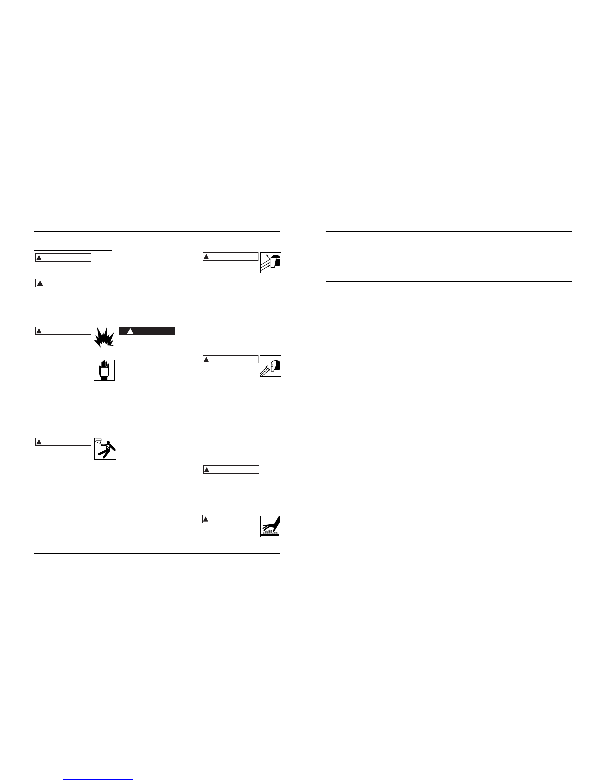
16 Fr
Soudeuse à dévidage de fil-électrode
Généralités sur la
sécurité (suite)
Avertis-
sement
indique : Manque de suivre cet
avertissement peut causer la perte de
vie ou des blessures graves.
Attention
indique :
Manque de suivre cet avertissement
peut causer des blessures de gravité
lègère ou moyenne ou des dommages
matériels.
REMARQUE : Remarque indique : des
renseignements additionnels
concernant le produit ou son utilisation.
Toujours avoir un extincteur
d’incendie disponible pendant
le soudage à l’arc.
Lire et comprendre toutes les
instructions avant de
mettre en marche ou de
procéder à l’entretien d’un
soudeur à l’arc électrique.
Manque de suivre les
précautions et les instructions peut
causer le dommage à l’équipement
ou blessures personnelles graves ou
la mort.
Toute installation, entretien,
réparation et utilisation de cet
équipement doit être effectué par
les personnes qualifiées
conformément aux codes nationaux,
provinciaux et locaux.
L’utilisation incorrecte des
soudeurs à l’arc électriques
peut avoir comme résultat,
secousse électrique, blessure et perte
de vie! Suivre toutes les précautions
indiquées dans ce manuel afin de
réduire le risque de secousse électrique.
Vérifier que toutes les pièces du
soudeur à l’arc soient propres et en
bon état avant de l’utiliser. S’assurer
que l’isolation sur tous câbles,
pistolets et cordons d’alimentation
n’est pas endommagé. Toujours
réparer ou remplacer les pièces
détachées endommagées avant
d’utiliser le soudeur. Toujours garder
les panneaux, les écrans de soudage,
etc, en place pendant le
fonctionnement du soudeur.
!
AVERTISSEMENT
!
AVERTISSEMENT
!
ATTENTION
!
AVERTISSEMENT
Toujours porter des vêtements
protecteurs et gants de soudage secs,
ainsi que des chaussures isolantes.
Toujours faire fonctionner le soudeur
dans un endroit propre, sec et bien
ventilé. Ne pas faire fonctionner le
soudeur dans un endroit humide,
trempe, pluvieux, ou malventilé.
S’assurer que l’objet sur lequel vous
travaillez soit bien fixé et mis à la
terre correctement avant de
commencer votre soudage à l’arc
électrique.
Le câble de soudage roulé devrait
être étendu avant l’utilisation afin
d’éviter le surchauffage et le
dommage à l’isolation.
Ne jamais
immerger
le fil ni le pistolet dans l’eau. Si le
soudeur devient trempe, il est
nécessaire qu’il soit complètement sec
et propre avant l’utilisation!
Toujours mettre l’équipement hors
circuit et le débrancher avant de le
déplacer.
Toujours brancher le conducteur de
travail en premier lieu.
Vérifier que l’objet sur lequel vous
travaillez soit mis à la terre
correctement.
Toujours mettre l’équipement de
soudage à l’arc électrique hors circuit
si hors usage et couper l’excès de fil
du pistolet.
Ne jamais permettre que votre corps
touche le fil fourré de flux et la terre
ou l’objet de travail mis à la terre en
même temps.
Les conditions et positions de
soudage difficiles peuvent poser des
risques électriques. Si vous êtes
accroupi, à genoux ou aux
élévations, s’assurer que toutes les
pièces conductrices soient isolées.
Porter des vêtements protecteurs
convenables et prendre ses
précautions contre les chutes.
Ne jamais essayer d’utiliser cet
équipement aux réglages de courant
ni aux facteurs d’utilisation plus haut
que ceux indiqués sur les étiquettes
de l’équipement.
!
DANGER
Ne jamais utiliser un soudeur à l’arc
électrique pour dégeler les tuyaux
congelés.
Les étincelles volantes et le
métal chaud peuvent causer
des blessures. La scorie peut
s’échapper quand les soudures se
refroidissent. Prenez toutes
précautions indiquées dans ce manuel
pour réduire la possibilité de blessure
par les étincelles volantes et le métal
chaud.
Porter un masque de soudure ou des
lunettes de sécurité avec écrans
protecteurs approuvés par ANSI
pendant le burinage ou l’ébarbage
des pièces en métal.
Utiliser des protège-tympans pour
le soudage aérien afin d’éviter que
la scorie ou la bavure tombe dans
vos oreilles.
Le soudage à l’arc électrique
produit une lumière intense
de la chaleur et les rayons
ultraviolets (UV). Cette lumière intense
et ces rayons UV peuvent causer des
blessures aux yeux et à la peau. Prenez
toutes précautions indiquées dans ce
manuel afin de réduire la possibilité des
blessures aux yeux et à la peau.
Toutes personnes qui utilisent cet
équipement ou qui sont dans
l’endroit pendant l’utilisation de
l’équipement doivent porter des
vêtements de soudage protecteurs y
compris : un masque ou un casque
de soudeur ou un écran avec un
filtre numéro 10 (au moins), des
vêtements incombustibles, des gants
de soudeur en cuir et la protection
complète pour les pieds.
Ne
jamais
observer le soudage à l’arc sans la
protection pour les yeux telle
qu’indiquée ci-dessus. Ne jamais
utiliser une lentille filtrante qui est
fendue, cassée ou classifiée moins que
le numéro 10. Avertir les autres
personnes dans l’endroit de ne pas
observer l’arc.
Le soudage à l’arc électrique
produit des étincelles et
chauffe le métal aux
températures qui peuvent causer des
brûlures graves! Utiliser des gants et
des vêtements protecteurs pendant
!
AVERTISSEMENT
!
AVERTISSEMENT
!
AVERTISSEMENT
!
AVERTISSEMENT
MANUAL
13
WG2063, 58-8027-4
Repair Warranty
Repair Warranty
This Mastercraft product carries a three (3) year repair warranty against defects in
workmanship and materials. At its discretion, Mastercraft Canada agrees to have any
defective part(s) repaired or replaced free of charge, within the stated warranty period,
when returned by the original purchaser with proof of purchase. This product is not
guaranteed against wear or breakage due to misuse and/or abuse.
This product is not guaranteed if used for industrial or commercial purposes.
TOLL FREE HELPLINE: 1-866-220-2097
Page 14
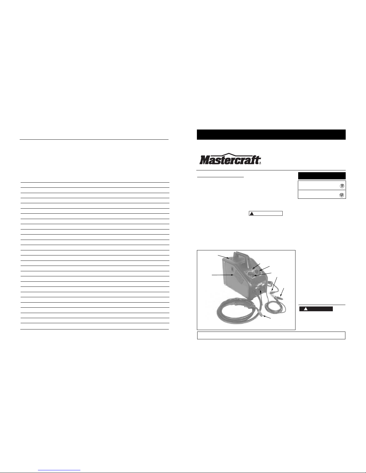
PIÈCES DÉTACHÉES ET COMMANDES
1. Pince de soudeur – s’attache à l’objet
de travail.
2. Torche à buse de 0,9 cm (0,035 po)
3. Cordon d’alimentation - se branche
dans une prise de courant de 115 V.
4. Voyant – le voyant s’active si le
thermostat éteint automatiquement
le soudeur.
5. Contrôle de vitesse de fil infini tourne au sens des aiguilles d’une
montre pour augmenter la vitesse et
au sens contraire des aiguilles d’une
montre pour diminuer la vitesse du fil.
6. Cadran de réglage de chaleur –
choisit le courant de soudure et met
l’appareil en marche. Quatre choix
possibles :
1 - 2 - 3 - 4.
7. Commande de polarité pour fil de
soudage sous gaz inerte ou à âme en
flux – pour changer à la polarité
d'électrode positive ou négative.
8. Branchement MIG de gaz
9. Compartiment d’alimentation du fil
Généralités sur la
Sécurité
Danger
indique :
Manque de suivre cet avertissement
causera la perte de vie ou des blessures
graves.
!
DANGER
S’il vous plaît lire et conserver ces instructions. Lire attentivement avant de monter, installer, utiliser ou de procéder à l’entretien du produit
décrit. Se protéger ainsi que les autres en observant toutes les instructions de sécurité, sinon, il y a risque de blessure ou dégâts matériels!
Conserver ces instructions comme référence.
15 Fr
IN972900AV 2/05
Soudeuse à dévidage
de fil-électrode
Description
Cette soudeuse à dévidage de filélectrode est conçue pour un courant
résidentiel standard de 115 V. Elle est
dotée d’un contrôle de vitesse de fil
continu pour choisir avec exactitude la
bonne vitesse d’alimentation du fil pour
les diverses conditions de soudage. Les
pièces internes sont protégées par un
thermostat.Ce système de soudure est
conçu pour être utilisé avec du fil de
soudage sous gaz inerte ou à âme en flux.
En sortant de l'usine, cette soudeuse peut
souder avec un fil de 0,024 po (0,6 mm) à
0,030 po (0,8 mm) de diamètre sous
protection gazeuse inerte (MIG) et de
0,030 po (0,8 mm) à 0,035 po (0,9 mm) de
diamètre dans le fil fourré. Un rouleau de
départ de fil fourré de 0,035 po (0,9 mm)
est inclus.
Déballage
Les accessoires de soudage pour le
soudeur se trouvent à l’intérieur du
Se référer à la page 21 pour les
instructions de remplacement du
cordon d’alimentation.
REMARQUE : gardez votre preuve d'achat datée jusqu'à la fin de la garantie !
Joignez-la à ce manuel ou classez-la dans un dossier pour plus de sécurité.
1-2-3 15 amp
4 20 amp
Sélecteur Disjoncteur ou
de chaleur fusible à retardement
Guide d’utilisation et de pièces de rechange WG2063, 58-8027-4
compartiment d'alimentation du fil
sur le côté de l’outil. Lors du
déballage, l’examiner soigneusement
pour rechercher toute trace de
dommage susceptible de s’être produit
en cours de transport. Assurer que tous
raccords, vis, etc., soient serrés avant de
mettre ce produit en service.
Rapportez tout article manquant ou
endommagé en composant le
1 866 220-2097.
EXIGENCES DE CIRCUIT
Cet
équipement requiert un circuit de 115 V unique.
Se référer au tableau suivant pour la
classificaton correcte de disjoncteur et de
fusible. Ne pas faire fonctionner autres
appareils, lampes ou outils sur ce circuit
pendant l’utilisation de cet équipement.
Les cordons prolongateurs ne sont pas
recommandés. Manque de suivre ces
recommandations peut résulter en
fusibles sautés et disjoncteurs déclenchés.
!
ATTENTION
Figure 1 - Commandes et pièces du soudeur
3
1
6
4
8
9
5
2
7
14
Wire Feed Arc Welder
Soudeuse à dévidage de fil-électrode
Notes
 Loading...