

Page 1
®
SAFETY & MAINTENANCE
MANUAL W/PARTS LIST
READ & FOLLOW ALL INSTRUCTIONS,
MTHC-20J-230
ULTI-PURPOSE
M
FLOOR SURFACING
MACHINE
AAddddrreessss
Parts and Service Center
777 South Street
Newburgh NY 12550-0606
PPhhoonnee
845/565/6623
FFaaxx
845/565/8894
ARNINGS & CAUTIONS
W
BEFORE USING THIS
FLOOR SURFACING MACHINE
This floor surfacing machine will afford you
many years of trouble free operating satisfaction if it is given proper care. All parts have
passed rigid quality control standards before
being assembled to produce the finished product. Prior to packaging, the units are again
inspected for assurance of flawless operation.
This floor surfacing machine was protectively
packed to prevent damage in shipment. We
recommend that upon delivery, remove the unit
from its carton and carefully inspect it for any
possible damage in transit. A warranty card is
affixed to the handle. It is your responsibility to
fill it out and send it to our office to register your
purchase and start your warranty. Failure to
send us this card in one week upon receipt of
the machine may void the warranty.
If damage is discovered, immediately notify the
transportation company that delivered your
floor machine. As a shipper, we are unable to
act upon any claim for concealed damage. You
must originate any claim within 5 days of the
delivery.
These instructions are for your protection and
information.
Failure to follow these precautions could result
in injury or discomfort.
Treat this floor surfacing machine as you would
any other high grade precision made product.
Throwing, dropping, unreasonable bumping
across thresholds and other misuse may result
in a damaged unit and invalidate the warranty.
PPLLEEAASSEE RREEAADD CCAARREEFFUULLLLYY!!
TThhiiss uunniitt iiss iinntteennddeedd ffoorr ccoommmmeerrcciiaall uussee..
PLEASE READ
CAREFULLY
BEFORE
OPERATING
SAVE THESE INSTRUCTIONS
PP
AAGGEE
11
PN 499676 Rev A - MTHC-20J-230 - Printed in USA 12/18/07
Page 2
IMPORTANT
WW
AARRNNIINNGG
::
SAFETY
INSTRUCTIONS
To reduce the risk of fire, electric shock or injury;
Read all instructions before using this floor machine.
11)) DDOO NNOOTT
plugged in when not in use. Unplug from the
outlet when not in use and/or before servicing.
22))
Electric shock could occur if exposed to rain.
Store indoors.
33))
This is
when used around or near children.
44))
Use only as described in this manual. Use
only the manufacturer's recommended attachments.
55)) DDOO NNOOTT
floor machine is not working as it should
because it has been dropped, damaged, left
outdoors, or dropped into water, contact the
manufacturer or authorized service center.
66)) DDOO NNOOTT
cord as a handle, close a door on cord, or pull
cord around sharp edges or corners.
run floor machine over the cord. Keep cord
away from heated surfaces.
77)) DDOO NNOOTT
hands.
88)) DDOO NNOOTT
leave the floor surfacing machine
NNOOTT
a toy. Close attention is necessary
use with damaged cord plug. If the
pull or carry by cord, use power
DDOO NNOOTT
handle the plug or operate with wet
put any object into motor openings.
99)) DDOO NNOOTT
unplug, grasp plug, not the power cord.
100))
1
Keep hair, loose clothing, fingers and all
parts of body away from moving parts.
1111)) DDOO NNOOTT
the manufacturer’s filters in place.
1122)) DDOO NNOOTT
oxygen are used.
1133)) DDOO NNOOTT
bustible liquids such as gasoline or use in areas
where they may be present.
1144)) DDOO NNOOTT
1155))
Replace damaged or worn parts immediately with genuine equipment parts to maintain
safety and protect your limited warranty.
1166))
Floor sanding can result in an explosive
mixture of fine dust and air. Use a floor sanding
machine only in a well ventilated area.
1177)) DDOO NNOOTT
when sander is not in use, this is a fire hazard.
This floor machine must be connected to a
properly grounded outlet only.
unplug by pulling on cord. To
use an optional vacuum without
operate where anesthetics and
use around flammable or com-
use an extension cord.
to leave sawdust in the filter bag
GROUNDING
INSTRUCTION
DD
AANNGGEERR
::
Improper use of the grounding plug can result in a risk of electrical shock.
This floor surfacing machine must be grounded. If it should malfunction or breakdown,
grounding provides a path of least resistance
for electrical current to reduce the risk of electric shock. This machine is equipped with a
Improper connection of the equipment-grounding conductor can result in a risk of
electrical shock. Check with a qualified electrician or service person if you are in doubt as
to whether the outlet is properly grounded. DO NOT modify the plug provided with the
machine. If it will not fit the outlet, have a proper outlet installed by a qualified electrician.
NNOOTTEE::
In Canada, the use of a temporary adaptor is not permitted by
the Canadian Electrical Code.
PP
AAGGEE
22
cord having an equipment-grounded plug. The
plug must be inserted into an appropriate outlet
that is properly installed and grounded in accordance with all local codes and ordinances
WW
AARRNNIINNGG
::
Page 3
CC
AAUUTTIIOONN
::
ATTACHMENT
When installing or changing the accessories, turn OFF the machine
and disconnect the power cord from the electrical outlet.
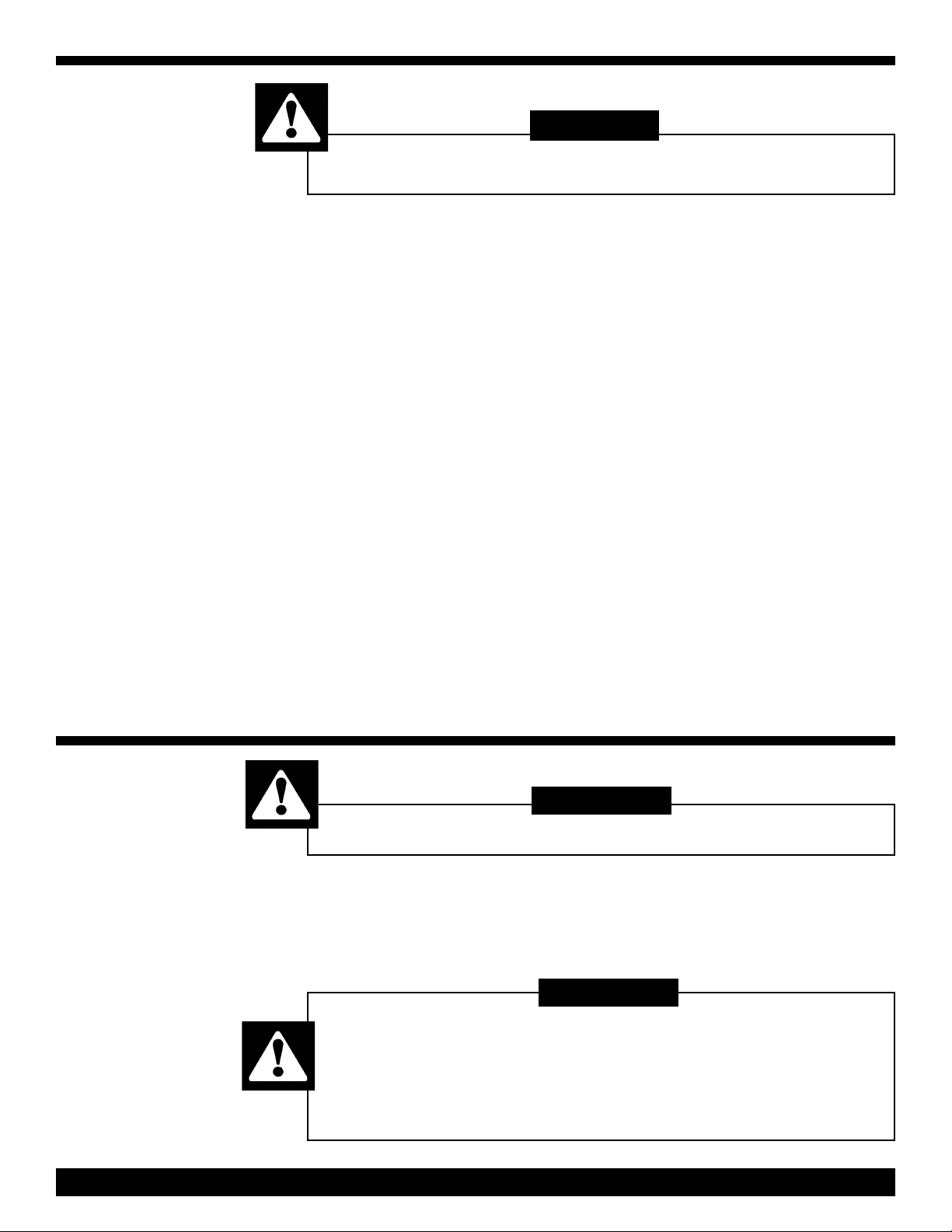
BBeeffoorree IInnssttaallllaattiioonn oorr CChhaannggiinngg ooff
AAttttaacchhmmeennttss::
1) Unplug the machine from the wall outlet.
2) Ensure handle is in the storage position
(straight up) and locked in place with the
quick release pin.
3) Tilt machine back by bracing it with your
foot until the handle is laying on the floor and
the three heads are fully exposed.
NNoottee::
It is recommended that a towel or pad is
placed under the machine to protect the floor.
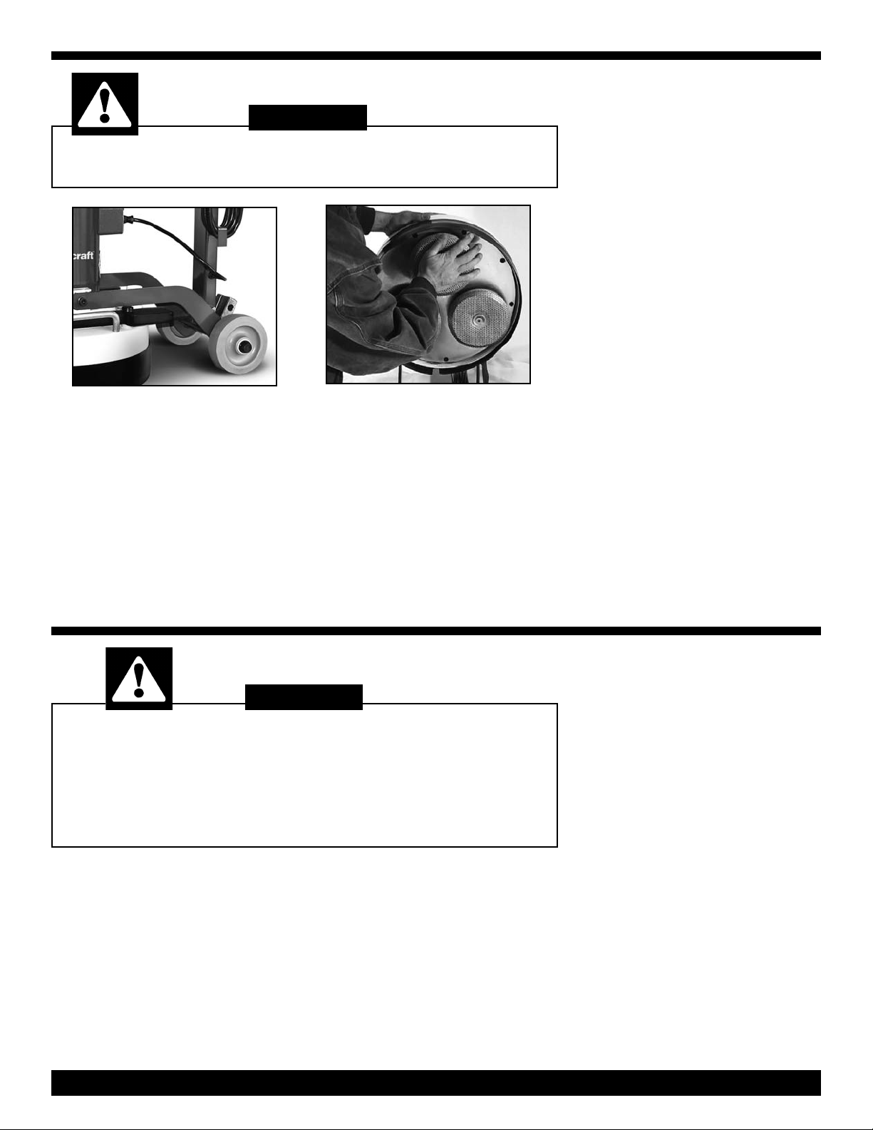
CChhaannggiinngg aanndd IInnssttaallllaattiioonn tthhee
AAttttaacchhmmeennttss::
1) Position the first attachment head at 12
o’clock.
2) Using both hands, reach beneath the
bottom side the attachment and pull up
towards yourself to free it from the sander.
3) Select the attachment required for the
job, and line up the holes on the attachment
with the four metal pins protruding from each
of the three heads.
INSTALLATION &
CHANGING
4) Push the attachments on by hand and if
necessary, carefully tap it into place with a
rubber mallet.
5) Repeat steps 1 thru 4 with the remaining
2 attachments.
6) Carefully raise the handle, supporting the
axle with your foot to control the head of the
machine as it is placed on the floor.
7) Since the attachments are different
heights you may need to adjust the dust skirt
to make sure it is level with the attachments.
This will ensure clean and virtually dust-free
operation.
9) To adjust skirt, align the skirt with the center of the machine and wrap it around.
10) Move the handle back to the operating
position and lock in place with the quick
release pin.
CC
AAUUTTIIOONN
DO NOT attempt to operate this unit if the
machine is not fully assembled.
When servicing or replacing an accessories turn OFF the
machine and disconnect from the power source.
Prior to operating the machine,
tilt machine back on transport wheels, turn ON the machine
and carefully lower the machine onto the working surface.
11))
Clear the floor of any materials or objects.
22))
Ensure handle is in the storage position
(straight up) and locked in place with the
quick release pin.
33))
Tilt the machine back until the handle is
laying on the floor and the three heads are
fully exposed.
44))
Select the accessory set required for the
job.
::
55))
Snap the accessory set onto the four
metal pins protruding from each of the three
heads.
66))
To replace, pull off the current accessory
set and replace with the new accessory set.
77))
Carefully raise the handle, supporting the
axle with your foot to control the machine
head as it is placed on the floor.
88))
Shift handle to the operating position and
lock in place with the quick release pin.
PP
AAGGEE
33
FLOOR SURFACING
MACHINE
OPERATING
INSTRUCTIONS
Page 4

MTHC-20J-230
ANDLE/BASE
H
ASSEMBLY
DRAWING &
ARTS LIST
P
______________________________________
RReeff PPaarrtt DDeessccrriippttiioonn QQttyy PPaarrtt
NNoo NNoo
______________________________________
1 Switch Box Plate 1 493481
2 Rubber Handle Grip 2 490180
3 Machine Switch 1 493074
4 Strain Relief Assembly 1 425427
5 50 Ft Power Cord w/Twist Lock 1 493163
6 Handle Assembly 1 498807
7 Quick Release Pin w/Cable 1 456896
8 Wire Retainer 1 456888
9 Motor Cord without Plug 1 490229
10 .37-16 X
11 Bronze Bushing 2 491055
12 Wheel Base Assembly 1 493708
13 6” X 2” Wheel 2 490903
14 Palnut 2 490881
______________________________________
1
/
2
” Shoulder Bolt 2 491063
PP
AAGGEE
44
Page 5

MTHC-20J-230
UTERBOWL ASSEMBLY
O
DRAWING
& PARTS L
IST
PP
____________________________________
RReeff PPaarrtt DDeessccrriippttiioonn QQttyy PPaarrtt
NNoo NNoo
____________________________________
1 3 HP Motor, 3450 RPM’s 1 491845
2 Pigtail 1 495786
3 Bowl Handle 2 490385
4
5 .38-16 X 1” Bolt 4 368830
6 20” Outer Bowl Assembly 1 496464
7 13/4” External Snap Ring 1 491292
8 Rubber Dust Skirt 1 491926
9 Velcro Strip 1 492019
10 28# Weight (Optional) 1 492442
11 Nyloc Nut 3 380784
12 Weight Knob 3 491632
13
14 Felt Gasket 1 493066
15 .37 Lockwasher 4 368849
____________________________________
55
AAGGEE
1
/
1
/
5
4
-20 X
/
8
” Screw 4 457310
4
-20 X .75” Screw 3 342831
Page 6

MTHC-20J-230
NNERBOWL
I
ASSEMBLY
DRAWING
& PARTS LIST
___________________________________
RReeff PPaarrtt DDeessccrriippttiioonn QQttyy PPaarrtt
NNoo NNoo
___________________________________
127/8Internal Snap Ring 1 490598
2 Bearing (6009-2RS) 2 490563
3 Large Bearing Spacer 1 490571
4 Outer Pulley Shaft 3 490547
5 20” Inner Bowl 1 491810
6 Center Cog Pulley 1 494836
7 Shaft Spacer 3 490555
81
9 Ball Bearing w/Seals 6 464910
10 Small Bearing Spacer 3 490474
11 Flange 1 490989
12 Low Profile Bolt 1 490997
13 3” ID x 6” OD Ring 3 222828
14 #10-32 x .5 Phillips Screw 9 377201
___________________________________
1
/2Internal Snap Ring 3 490466
___________________________________
RReeff PPaarrtt DDeessccrriippttiioonn QQttyy PPaarrtt
NNoo NNoo
___________________________________
15 Accessory Pins 12 490458
16 .62-11 Nylock Nut 3 490628
17 Washer 3 490636
18 Felt Gasket 3 491373
19 Aluminum Ring 3 490652
20 Pop Rivet 12 456918
21 .25-20 x .5 Phillips Screw 9 331740
22 #14, .43”OD Lockwasher 9 491012
23 Aluminum Cover Plate 1 491888
24 Belt
25 48 High Tooth Pulley 1 490512
26 48 Middle Tooth Pulley 1 490490
27 48 Low Tooth Pulley 1 490415
(240-L050) 3 491918
___________________________________
PP
AAGGEE
66
Page 7

WW
AARRNNIINNGG
IF THIS FLOOR MACHINE IS USED FOR SANDING,
DO NOT LEAVE SAWDUST IN THE FILTER BAG WHEN THE
MACHINE IS NOT IN USE. THIS IS A FIRE HAZARD.
::
VACUUM
OPERATING
INSTRUCTION
This machine can be used with a variety of
vacuums to pick up wood and concrete
dust.
Operation of the vacuum cleaner must be in
accordance with specific manufacturer’s
safety & operation instructions.
11))
Unplug the
motor power
cord from the
handle.
22))
Pull the speed pin from the handle and
remove the handle. Carefully set aside the
handle.
Recommend separate dedicated power
source for machine and vacuum.
The vacuum hose must be attached to the
1
/
2
” hose barb on the outer bowl of the
1
floor machine.
BELT CHANGING INSTRUCTIONS
33))
Turn sander chassis upside down on a
table resting on the motor cover.
44))
Remove pads/attachments (see page 3
for instructions.)
55))
Remove the 9 Flat head screws and
beveled washers from cover plate.
66))
Remove the cover plate from inner bowl.
During operation, periodically check the
vacuum. When the cloth or paper filter bag
is 3/4 full or dust is forming around the bottom of the machine, it MUST be emptied.
77))
Vacuum up the dust and debris from inner
bowl.
88))
Remove the old belt or belts by pulling
upwards and and roll off using a screwdriver
while turning the pulley.
99))
Roll new belt or belts back on the pulley.
1100))
Reassemble the machine reversing the
above steps.
CC
AAUUTTIIOONN
This machine is designed for surfacing concrete and sanding wood floors.
All operators and maintenance personnel should read and
understand the safety procedures with this floor machine.
11))
All personnel in the immediate work area
must wear safety glasses with side shields
whenever the machine is in operation.
Protective clothing is also recommended.
Long sleeve shirts and safety shoes should
be worn. Avoid wearing loose clothing.
11))
Unplug the machine.
22))
After each use, wipe off machine with a
clean cloth.
33))
Empty the vacuum you are using in
accordance with specific manufacturer’s
safety & operation instructions.
::
22)) DDOO NNOOTT
attachments while the machine is running or
connected to a power source.
33)) DDOO NNOOTT
or in areas where liquids could enter the
electrical components of the machine.
55))
Check for loose parts and fasteners.
66))
Check the power cord for any breaks in
the wire. Breaks will most likely occur near
the plug or switch. Repair or replace any
breaks immediately.
attempt to service or replace
operate this machine in the rain
GENERAL
SAFETY
PRECAUTIONS
44))
Keep the power cord away from the
revolving heads to avoid damage.
55))
Check the main power supply to assure
that you are connecting the equipment to a
proper dedicated service.
MACHINE
MAINTENANCE
PP
AAGGEE
77
Page 8

TROUBLE SHOOTING GUIDE
PROBLEM: Motor will not run.
Possible Cause Possible Solution
11))
Defective switch.
22))
Defective power cord or wiring.
33))
Defective motor.
44))
Blown fuse or tripped circuit breaker at wall panel.
55))
Power cord not plugged in properly or damaged.
PROBLEM: Machine bogs down and runs slow.
Possible Cause Possible Solution
11))
Defective capacitor or switch.
22))
Circuit may be overloaded with more than one appliance.
33))
Low line voltage in building.
ny.
PROBLEM: Motor runs, driver will not rotate.
Possible Cause Possible Solution
11))
Belts are broken.
11))
Check switch, replace if defective.
22))
Check and replace if defective.
33))
Have motor checked by an authorized service center.
44))
Replace fuse or reset circuit breaker. If this doesn't correct the
problem, have the sander checked by an authorized service center.
55))
Plug in power cord properly or replace power cord if damaged.
11))
Have machine checked by an authorized service center.
22))
Plug floor machine into a dedicated power outlet.If the problem still
exists there could be a short.Have the floor machine checked by an
authorized service center.
33))
If wiring is old in the building have voltage checked by the power compa-
11))
Contact the manufacturer or authorized service center.
PROBLEM: Noisy machine or vibration.
Possible Cause Possible Solution
11))
Defective motor.
22))
Attachment is not level or securely attached.
11))
Contact the manufacturer or authorized service center.
22))
Level attachment and make sure all fasteners are secure.
WARRANTY
This machine is warrantied against
defects in material and workmanship for 1
year, except for normal wear items listed
below, from the date of delivery to the
original purchaser. The warranty period is
subject to the conditions below:
Normal Wear Item
Warranted Up to 90 Days:
Normal wear items will be warranted from
manufacturing defects from date of purchase including but not limited to the following items:
Accessories; Attachments; Belts;
Bearings; Casters; Electric Cords;
Finishes; Filters; Pad Holder;
Switches; and the like.
Warranty is NULL and VOID for the
following:
1) Damage, defects, malfunctions or other
failures caused by not using the electric
current indicated on the spec plate.
2) Damage or defect caused by accident;
misuse; neglect; abuse; fire; etc.
4) Failure due to lack of proper maintenance and care (including cleaning).
5) Any unauthorized design alterations,
adjustments and/or repairs performed on
this machine.
6) Use of parts not approved by the
machines manufacturer will void all warranties.
7) Damage in transit.
Stated Warranties
This Warranty is in lieu of and excludes all
other warranties expressed or implied. Any
statutory implied warranties, including the
warranty of merchantability or fitness for a
particular purpose, are expressly excluded.
We will not be liable for any other damage
including but not limited to indirect or spe
cial consequential damages arising out of
or in connection with the furnishing, performance, use or inability to use the
machine. This remedy shall be the exclusive remedy of the buyer. The warranty is
limited to the warranty.
Warranty Claim Procedure
If a difficulty develops during the warranty
period, contact the authorized distributor
form whom the unit was purchased. The
Warrantor may elect to require the return
of the machine or components to validate
the claim. any defective part to be
returned must be properly packed and
shipped freight pre-paid to an Authorized
Distributor/Service Center.
Note: Because this machine is intended
for commercial and/or industrial use the
warranty is limited and not applicable to
persons purchasing or using this equipment for personal, family or household use
in which case the 90 day rule applies.
PN 499676 Rev A - MTHC-20J-230 - Printed in USA 12/18/07
PP
AAGGEE
88
 Loading...