

Page 1
READ AND FOLLOW ALL
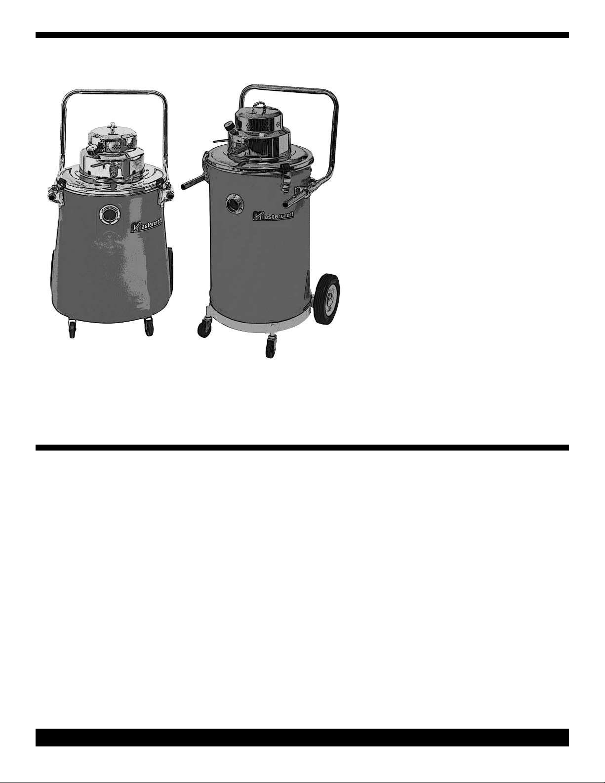
COMPRESSED
AIR-OPERATED
ACUUM CLEANERS
V
SAFETY,
PERATION &
O
AINTENANCE
M
MANUAL
This unit is intended for commercial use.
INSTRUCTIONS, WARNINGS & CAUTIONS
BEFORE USING THIS VACUUM.
This vacuum will afford you many years of
trouble-free operating satisfaction, provided
it is given proper care. All parts have passed
rigid quality control standards prior to being
assembled to produce the finished product.
Prior to packaging, this vacuum was again
inspected for assurance of flawless assembly.
This vacuum is protectively packed to prevent damage in shipment. We recommend
that upon delivery, unpack the unit and
inspect it for any possible damage. Only a
visual examination will reveal damage that
may have occurred.
If damage is discovered, immediately notify
the transportation company that delivered
your vacuum. As a shipper, we are unable to
report any claim for damage. You must originate any claim within 5 days of delivery.
This manual is for you protection and information. PLEASE READ CAREFULLY since
failure to follow precautions could result in
discomfort or injury. Read this manual completely before operating this vacuum. It is
important to follow instructions in this manual to prevent the possibility of injury or damage to the user and/or vacuum.
Treat this vacuum as you would any other
high grade precision made product.
Dropping, unreasonable bumping across
thresholds and other misuses may result in
a damaged unit which will not be covered by
the warranty.
PLEASE READ
CAREFULLY
EFORE
B
PERATION
O
SAVE THESE INSTRUCTIONS
PAGE 1
Air Vacuum Manual - PN 313491 Rev B - Printed in USA 04/26/05
Page 2
IMPORTANT
SAFETY
INSTRUCTIONS
VACUUM
SSEMBLY
A
1. Air supply should not exceed 150 PSI.
2. Use compressed air line rated for 200
PSI or better.
3. Water separator must be used on compressed air line.
4. DO NOT used to pickup flammable
and/or combustible materials.
6. Air control valve must be OFF before connecting to compressed air line, than open
valve slowly making sure not exceed the 150
PSI rated pressure.
5. When the unit is ON, never allow hair,
fingers, or loose clothing to come near
intake, suction ports or nozzle.
7. The cloth filter must be in place for dry
pick-up to prevent clogging and contamination to venturi and exhaust filter. When use
for liquid pick-up a wet adaptor must be
used.
8. Replace damaged or worn parts immediately with genuine original equipment parts
to maintain safety and to protect your limited
warranty.
CAUTION:
The air supply must be turned OFF when the vacuum action is stopped.
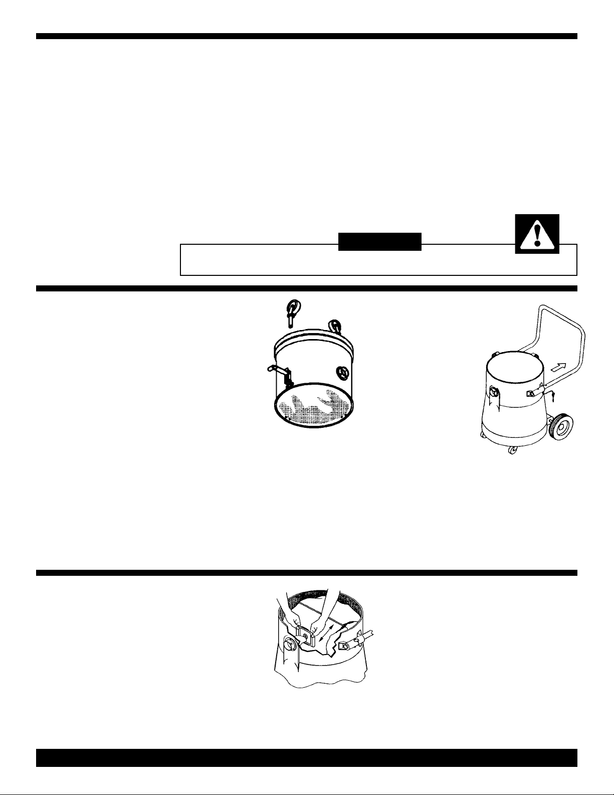
4-Caster
Tanks
Glidemobile
Style
w/Handle
FILTER
INSTALLATION
This vacuum
requires some
assembly.
1] Carefully remove and set aside motor
head and filter assembly
2] Turn tank upside down.
Poly Tanks: Press caster into plastic socket
until bottom of stem fits flush against plastic
socket.
Steel Tanks: Insert casters into caster
mount assemblies.
Cloth and
Paper Bag
Filter:
1) Disengage the
holdown clamps.
2) Remove the air head and set aside.
This vacuum is
shipped with the
handle in the storage
position and it must
be moved to the
operating position.
1) Firmly grasp the speed pins on each side
of handle and pull up and out.
2) Pulling the handle slowly away from tank,
align front handle holes with the holes in the
handle bracket.
3) Insert speed pins through holes on both
sides, locking handle in position.
4) Expand filter bag pleats, then grasp
scored ends of the cardboard and pull forward completely onto inlet tube as close to
tank wall as possible.
5) Position cloth filter assembly on the tank,
then place motor head on tank and close
clamps.
3) Empty filters, hose and other attachments that may be packed in the tank.
PAGE 2
Page 3

Paper Filter
Bag Removal:
DRY FILTER
REMOVAL &
MAINTENANCE
Dry Filter Assembly
Maintenance
In order to maintain maximum efficiency of
the vacuum cleaner it is important to clean
the cloth filter each time the tank is emptied. To clean the cloth filter, shake off loose
particles and brush exposed surface with a
soft bristle brush
NOTE: DO NOT WASH, shrinkage to the
cloth and damage to the gasket can occur.
This air vacuum is designed for wet or dry
pick-up. In order to use this vacuum for wet
pickup you must order the optional wet pickup adaptor.
1) Remove the motor head
and cloth filter assembly.
Set aside.
2) Lay vacuum tank on its side with inlet
tube on top.
3) Pull the bag out of tank, using care not to
puncture bag with inlet tube.
4) Reseal the cardboard flap that covered filter bag opening.
Install a new paper filter bag.
Removal of Liquid From
Vacuum Tank:
Tank Without Drains
1) Disengage the holdown clamps on tank.
2) Remove air head and wet pickup adaptor,
carefully place to one side.
ET
W
OPERATION
Wet Pick-Up
Adaptor Installation:
The safety float located in the protective
frame of the wet adaptor stops the vacuum
action of air head when maximum recovery
of liquid is reached.
1) Disengage the holdown clamps. Remove
air head, dry filter assembly and disposable
paper filter bag.
2) Set wet adaptor on tank, replace air head
and snap down clamps.
Wet Pickup
Maintenance:
DO NOT store the vacuum with any liquid
inside the tank. Before storing or converting
over for dry pickup, run the emptied vacuum
for approximately five minutes to eliminate
moisture in the tank, hose and attachments.
3) Pour liquid from tank into suitable drain.
Tanks w/Drain Valves
1) Center the drain valve over a drain in the
floor.
2) Open drain valve by turning valve counterclockwise and continue turning until the
desired flow is reached.
3) After tank is drained, and before closing
the drain valve check for any obstruction
that will prevent valve from sealing. Turn the
valve clockwise until it is fully closed and
sealed.
Tanks w/Gate Valves
1) Center the tank's gate valve over a floor
drain.
2) Pull up on the gate valve handle to empty
the tank.
PAGE 3
Page 4

TOOLS & ATTACHMENT ASSEMBLY
Hose & Swivel
Connector
The hose and swivel connector are preassembled at the factory. To attach the
swivel connector to intake fitting on vacuum tank:
1) Line up the slots in the swivel connector with retaining rivets on the intake.
2) Insert swivel connector and twist
clockwise until rivets reset against slot
end.
Wand
TROUBLE
PROBLEM:
SHOOTING
GUIDE
Assembly
1) Align the button lock of the upper
wand section with the opening for button
lock in the lower wand section.
2) Push sections together, until the lock
is accomplished.
3) To attach hose to wand, slide free
end of hose onto the grooved end of
upper wand.
Assembly
1) Turn the wand nut counterclockwise
approximately four (4) complete turns.
2) Insert the tool into wand and coupling.
3) While holding the tool in place, turn
nut clockwise until wand nut is fully
locked.
Tool
Loss of vacuum.
CAUSE: SOLUTION:
1. Full paper filter bag. 1. Replace the paper filter bag.
2. Dry filter assembly clogged. 2. Clean the cloth filter.
3. Clogged hose, wand, or air supply. 3. Remove obstruction.
4. Tank rim damaged. 4. Replace the tank.
5. Air supply stops. 5. Check for a blockage and remove.
6. Loss of air supply. 6. Check to see if there is a minimum
operating pressure of 90 PSI.
7. Gasket worn. 7. Replace the gasket.
8. Float not functioning. 8. Check to see if the ball on the rod
moves freely or tank is fill.
PROBLEM:
CAUSE: SOLUTION:
1. Full paper filter bag. 1. Replace the paper filter bag.
Address:
777 South Street
Newburgh, NY 12550-0606
TEL:
(800) 835-7812
(845) 565-8850
FAX:
(800) 752-6883
(845) 565-9392
URL:
www.mastercraftusa.com
E-Mail:
techsupport@mastercraftusa.com
Air Vacuum Manual - PN 313491 Rev B - Printed in USA 04/26/05
2. Paper filter bag not installed 2. Reinstall or replace the paper filter
properly or off the inlet tube. bag properly.
3. Cloth filter is dirty. 3. Clean cloth filter.
4. Cloth filter or paper filter bag is torn. 4. Replace damaged filter.
5. Paper filter bag is not installed. 5. Install paper filter bag.
PROBLEM:
CAUSE: SOLUTION:
1. Tank is full of liquid. 1. Empty the tank.
2. Foamy liquid is being picked up. 2. Add defoamer to the tank.
Dust blowing from vacuum when running.
Water blowing from vacuum when running.
PAGE 4
 Loading...