

Page 1
INSTRUCTION MANUAL
MIG/FLUX-CORE WIRE FEED
WELDER KIT
058-8195-2
Page 2

Quick Start Guide
If any parts are
missing or damaged,
or if you have any
questions, please call
1-800-689-9928.
Read and understand this instruction manual
thoroughly before using the product. It contains
important information for your safety as well as
operating and maintenance advice.
Keep this instruction manual for future use. Should
this product be passed on to a third party, then this
instruction manual must be included.
MIG/FLUX-CORE WIRE FEED WELDER KIT 058-8195-2
Page 3
QUICK START GUIDE
MIG/FLUX-CORE WIRE FEED WELDER KIT 058-8195-2
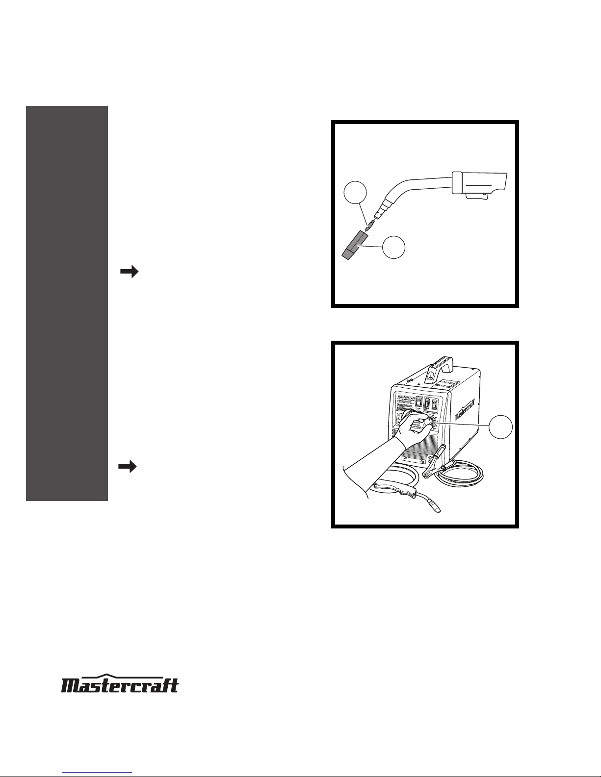
STEP 1
Installing the wire
Remove the nozzle (1) and contact tip (2) from
the end of the torch assembly. Identify the
leading end of the wire secured on the edge of
the wire spool. Place the spool on the hub with
the wire passing from the bottom of spool into
the drive mechanism.
pages 16-17, steps 1-4
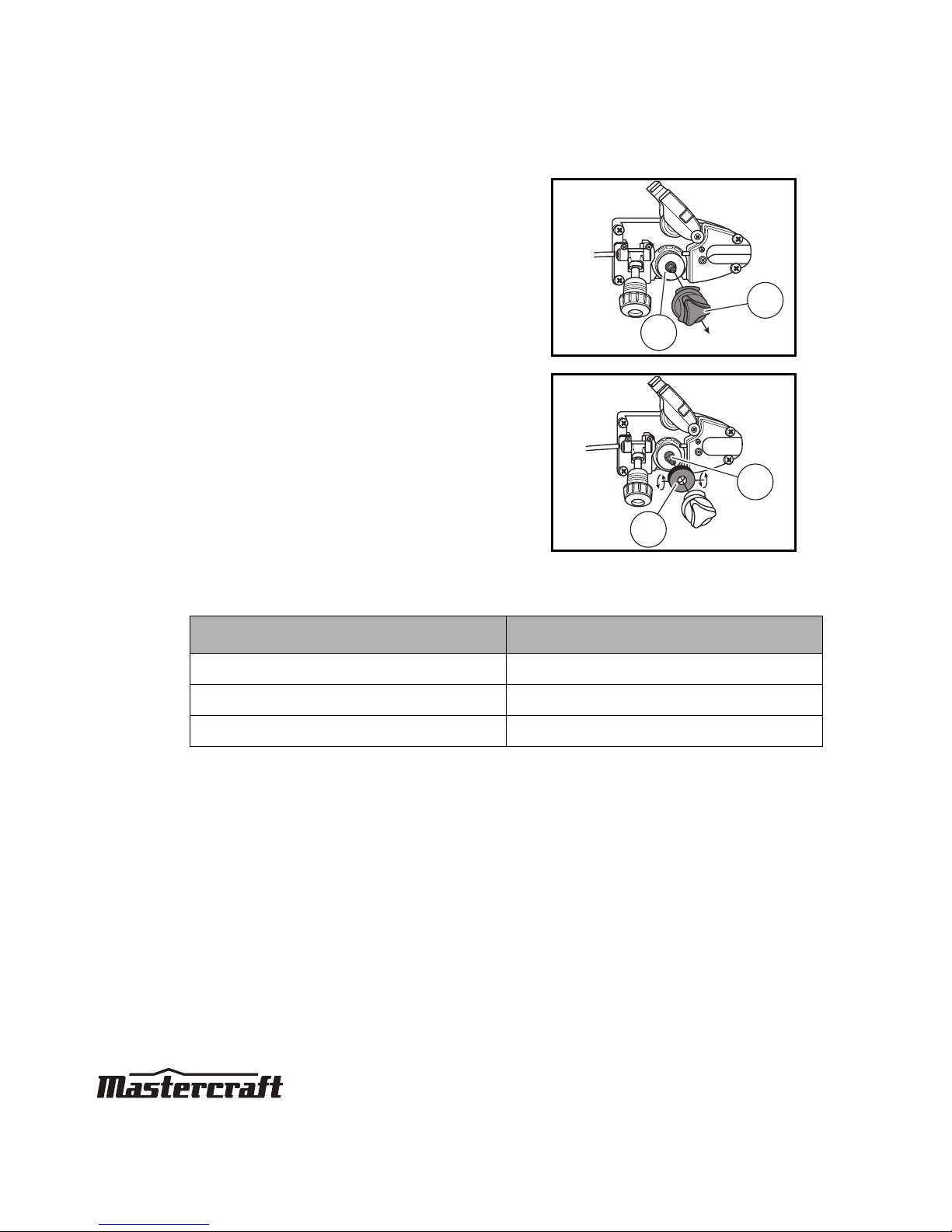
STEP 2
Setting the wire tension
Press the trigger on the gun. Turn the drive
tension adjustment knob (1) clockwise, and
increase the drive tension until the wire seems
to feed smoothly without slipping.
page 18, steps 1-2
MC-588195-06
1
2
MC-588195-24
1
Page 4
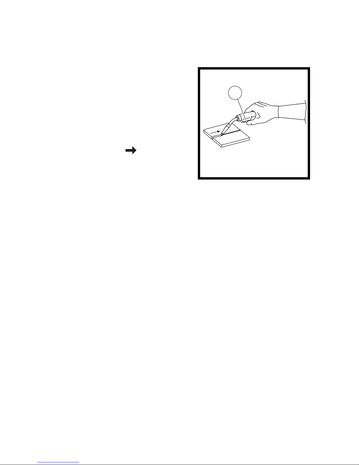
STEP 3
Operation
Hold the torch in one hand and turn the wire
speed dial with the other hand to its maximum
position. Pull the trigger (1) on the torch to
start an arc. Drag the torch toward the user
while simultaneously turning the wire speed
dial counterclockwise. page 20,
steps 4-5
(Please see page 21 for welding techniques if
needed.)
MC-588195-25
1
Page 5

TABLE OF CONTENTS
MIG/FLUX-CORE WIRE FEED WELDER KIT 058-8195-2
2
QUICK START GUIDE
TECHNICAL SPECIFICATIONS 3
SAFETY GUIDELINES 4–8
KEY PARTS DIAGRAM 9
IMPORTANT INFORMATION 10–13
ASSEMBLY INSTRUCTIONS 14–18
OPERATING INSTRUCTIONS 19–27
MAINTENANCE 28
TROUBLESHOOTING 29–30
MAIN CIRCUIT CHART 31
EXPLODED VIEW 32
PARTS LIST 33
WARRANTY 34–35
Page 6
TECHNICAL SPECIFICATIONS
3
MIG/FLUX-CORE WIRE FEED WELDER KIT 058-8195-2
POWER SUPPLY single-phase, 120 V, 60 Hz
NO-LOAD VOLTAGE 30V
OUTPUT CURRENT 35-80 A (Peak 130 A)
DUTY CYCLE 20% @ 80 A
WIRE USED MIG and flux-core wire
WIRE DIAMETER 0.023", 0.030", 0.035"
DIMENSIONS (L x W x H) 17.6" x 9.4" x 14.5"
WEIGHT 62 lb 10 oz
(28.42 kg)
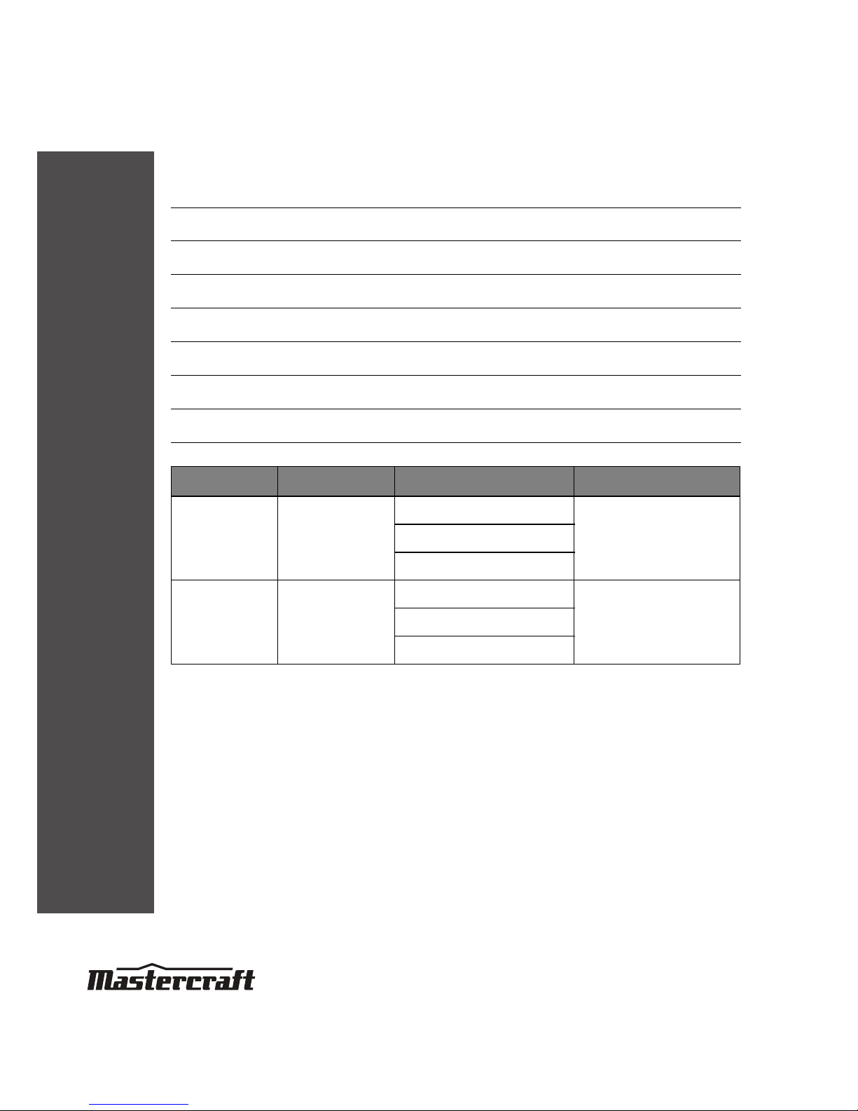
Welding mode Materials For metal thickness Use wire size
Flux core Steel
20-gauge-5/32"
0.03" (1/32") 0.8 mm
0.035" (5/128") 0.9 mm
5/128-5/32"
1.0-4.0 mm
MIG Steel, Stainless steel
20-gauge-1/8"
0.03" (1/32") 0.8 mm
0.023" (3/128") 0.6 mm
5/128-1/8"
1.0-3.0 mm
Page 7

SAFETY GUIDELINES
4
MIG/FLUX-CORE WIRE FEED WELDER KIT 058-8195-2
This manual contains information that relates to PROTECTING PERSONAL SAFETY and PREVENTING
EQUIPMENT PROBLEMS. It is very important to read this manual carefully and understand it
thoroughly before using the product. The symbols listed below are used to indicate this information.
Note- The word “Note” is used to inform the
reader of something he/she needs to know about
the tool.
PERSONAL SAFETY
These precautions are intended for the personal safety of the user and others working with the user.
Please take time to read and understand them.
DANGER!
Potential hazard that will result in serious
injury or loss of life.
WARNING!
Potential hazard that could result in
serious injury or loss of life.
CAUTION!
Potential hazard that may result in
moderate injury or damage to equipment.
Page 8
SAFETY GUIDELINES
5
MIG/FLUX-CORE WIRE FEED WELDER KIT 058-8195-2
DANGER!
Potential hazard that will result in serious injury or loss of life.
• Keep children or other personnel away from the work area while welding. Do
not allow children to handle the welder.
• Do not use the welder in the presence of flammable liquids or gases. Sparks
that are created during use may ignite gases.
• Do not operate the welder in humid, wet, or poorly ventilated areas.
• Use appropriate shield to prevent other personnel from being affected by
harmful rays.
• Always ensure that a fire extinguisher is available in adequate distance
within the welding environment.
• Do not repair or maintain the welder while the power is on.
• Risk of electric shock: Do not touch electrical live parts or metal
components connected to the welding wire, as doing so may cause fatal
shock and severe burns. Secure the ground lead before welding. Wear dry
protective apparel like coat, shirt, gloves, and insulated footwear.
• Risk for breathing: Never directly inhale the emission of harmful fumes when
welding on coated materials like galvanized, cadmium plated or contacting
zinc, mercury, or barium.
• Risk of fire: Do not weld on containers or pipes that contain flammable,
gaseous, or liquid combustibles. Remove all flammable materials within 35
feet of the welding arc or tightly cover the flammabe materials with fireproof
covers. To prevent any unintended arcs after welding, cut off the excess wire
that extends past the end of the nozzle more than ¼".
• Risk of burns: Do not touch the welded materials with bare hands, as the
welded materials are hot and can cause severe burns
.
Page 9

SAFETY GUIDELINES
6
MIG/FLUX-CORE WIRE FEED WELDER KIT 058-8195-2
• Risk of explosion: Keep high pressure shielding gas cylinder away from
welding or electrical circuits. Do not touch the cylinder with MIG gun and do
not weld on the cylinder. Use proper regulators, gas hoses, and fittings for
the specific application.
• Do not expose the welder to rain.
• Risk of UV and IR arc rays: Do not look at the welding arc without proper eye
protection, as the welding arc produces ultraviolet (UV) and infrared (IR) rays.
Use screens or other barriers to protect other personnel from the rays.
Page 10

SAFETY GUIDELINES
7
MIG/FLUX-CORE WIRE FEED WELDER KIT 058-8195-2
WARNING!
Potential hazard that could result in serious injury or loss of life.
•
Do not allow unskilled or untrained individuals to install and operate this
welder.
• Before operating the welder, check the insulation of the ground cable, power
cord, and welding cable for damage. Replace or repair the damaged
components before using the welder.
• Keep hands and fingers away from moving parts and stay away from the
drive rolls while the welder is in use.
• Do not allow any body part of the user to come in contact with the welding
wire while holding the welding gun.
• Do not allow the user to drape cables over or around the body.
• Do not point MIG gun toward the user or other personnel.
• Do not allow a person to use electronic devices such as pacemakers in the
welding area.
• Consult a doctor before using any electric arc welder or cutting device.
Page 11
SAFETY GUIDELINES
8
MIG/FLUX-CORE WIRE FEED WELDER KIT 058-8195-2
Note: Recycle the unwanted materials rather than disposing of it as waste. Sort the tools, hoses, and
packaging in specific categories and take to the local recycling center or dispose of it in an
environmentally safe way.
CAUTION!
Potential hazard that may result in moderate injury or damage to
equipment.
• Do not operate the welder if the output cable electrode, MIG gun, wire or
wire feed system is wet. All the components and the welder must be
completely dry before attempting to use the welder.
• Keep the welder in the OFF position when it is not in use.
• Do not wear watches, rings, bracelets, or loose clothing when using the
welder.
• Maintain a correct position while using the welder. Mount the welder on a
secure bench or cart to prevent if from tipping over or falling.
• Connect the ground lead as close to the area being welded to ensure proper
ground connection.
• Wear a full covered helmet, proper gloves, and protective clothing such as
leather shirt, coat, pant, and insulated footwear to prevent the skin from
being exposed to hot metals while welding.
• Do not overload the welder to prevent it from being heated. Allow proper
cooling time between duty cycles.
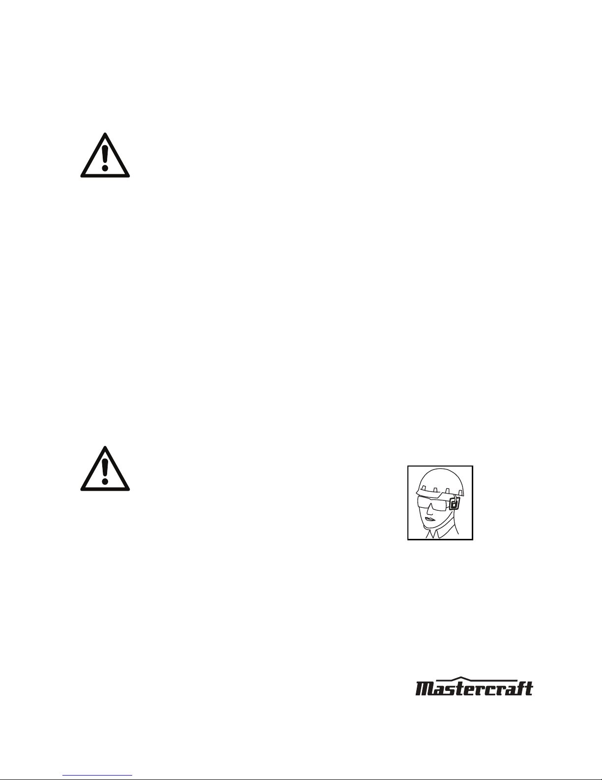
• Use safety goggles and ear protection:
Wear safety glasses with side shields when operating the
tool and verify that others in the work area are also wearing
safety glasses. Safety glasses must conform to American
National Standards Institute (ANSI Z87.1) requirements and
must provide protection from flying particles from the front
and the sides.
Always wear ear protection to help prevent hearing damage
and loss. Failure to comply may result in moderate injury.
MC-OM-01
Page 12
KEY PARTS DIAGRAM
9
MIG/FLUX-CORE WIRE FEED WELDER KIT 058-8195-2
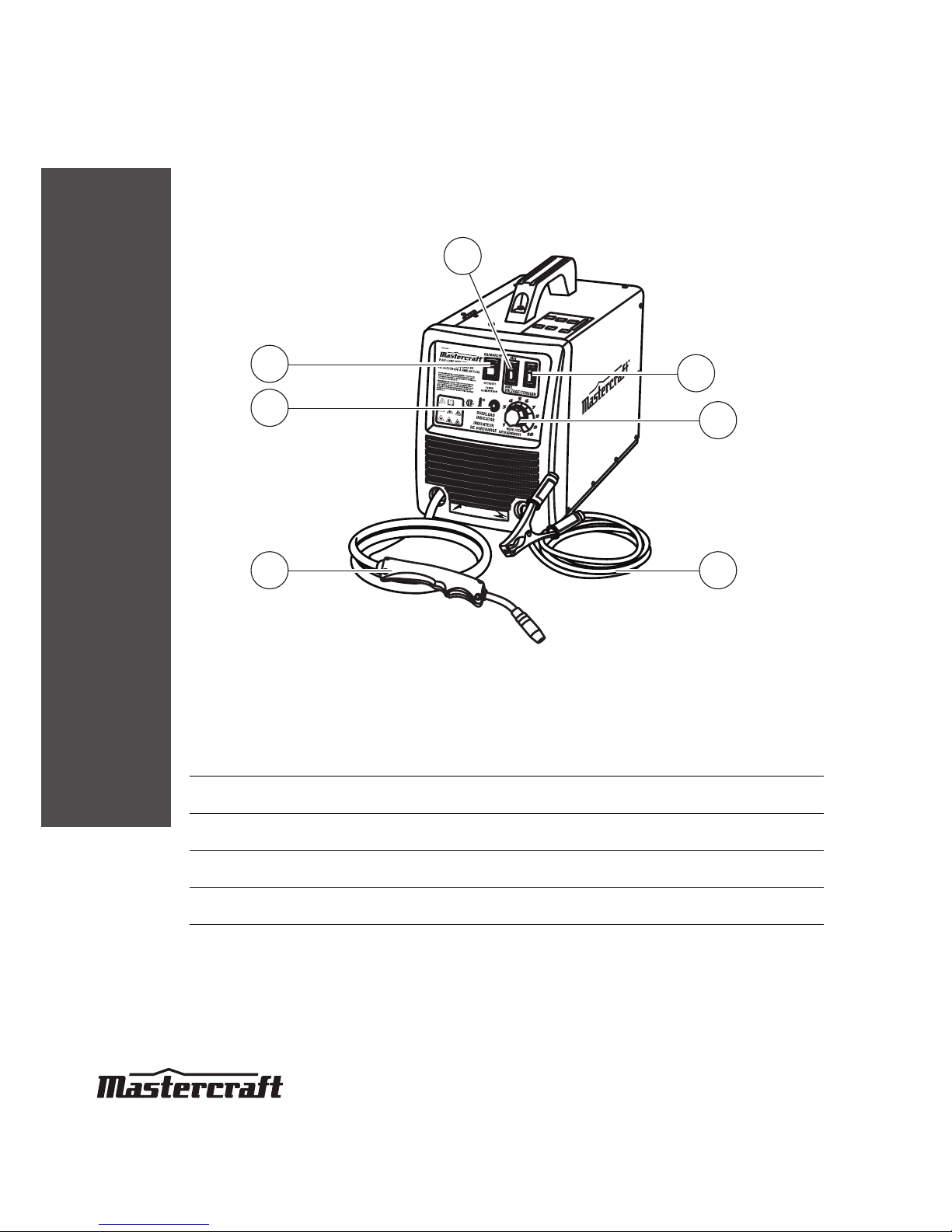
No. Description No. Description
1 MIN/MAX voltage setting 5 MIG torch
2 1/2 voltage setting 6 Thermal overload indicator
3 Wire feed setting 7 ON/OFF switch
4 Ground cable and clamp
1
6
7
2
3
4
MC-588195-01
5
Page 13

IMPORTANT INFORMATION
10
MIG/FLUX-CORE WIRE FEED WELDER KIT 058-8195-2
General usage description
The Mastercraft® portable and gasless MIG/Flux-Core Wire Feed Welder Kit uses AC single phase
120V, 60 Hz/20A with a time delayed fuse or circuit breaker. The kit provides two heat settings,
infinite wire speed control, overload and thermal protection. The welder kit can be used for welding
mild steel 20 gauge to 1/8" using flux core wire only in light industrial applications.
Guidelines for proper usage and description
REMOVING FROM CARTON
1. Remove cartons, bags, or styrofoam containing the welder and accessories.
2. Check the contents with the packaging list below.
After unpacking the welder unit, inspect for any damage that may have occurred during transit.
Check for loose, missing, or damaged parts. A shipping damage claim must be filled with carrier.
ON/OFF switch
This switch is used to turn the power supply of the welder kit ON and OFF through the main
transformer and control circuit.
MIN/MAX 1/2 voltage setting
Two adjustment switches are provided on the front panel of the welder kit, for setting the minimum
and maximum values of votage and tension. Refer to the set up chart for initial adjustment of the
voltage setting.
ITEM QTY.
Portable MIG welder 1 unit
Contact tip, 0.023" 0.030" 0.035" 1 pc
Sample spool flux core wire, 0.030" 1 LBS
Sample spool solid wire, 0.023" 1/2 LBS
Welding mask 1 pc
Chipping hammer/wire brush 1 pc
Instruction manual 1 manual
Handle 1 pc
Page 14
IMPORTANT INFORMATION
11
MIG/FLUX-CORE WIRE FEED WELDER KIT 058-8195-2
Wire feed setting
This setting adjusts the wire feed speed.
Ground cable and clamp
The ground cable and the clamp are attached to the workpiece to form a closed circuit which allows
the flow of current needed to weld.
Welding Cable and MIG gun/torch
The welding wire is driven through the welding cable and the MIG gun/torch to the workpiece. It is
attached to the drive system and the gun trigger activates the drive motor.
Thermal Indicator
If the duty cycle of the welder kit exceeds the maximum level, the internal temperature of the welder
kit will exceed the allowable operating range, which in turn makes the thermal overload light glow
and the welder kit to be shut down automatically. Allow the welder kit to cool down for 20 minutes
until the thermal overload light turns OFF automatically. The temperature of the welder kit is then
within the allowable operating range.
Power cord
The power cord connects the welder to the 120 V power supply. Connect the 15 A plug into a
120 V/20 A receptacle to supply power to the welder.
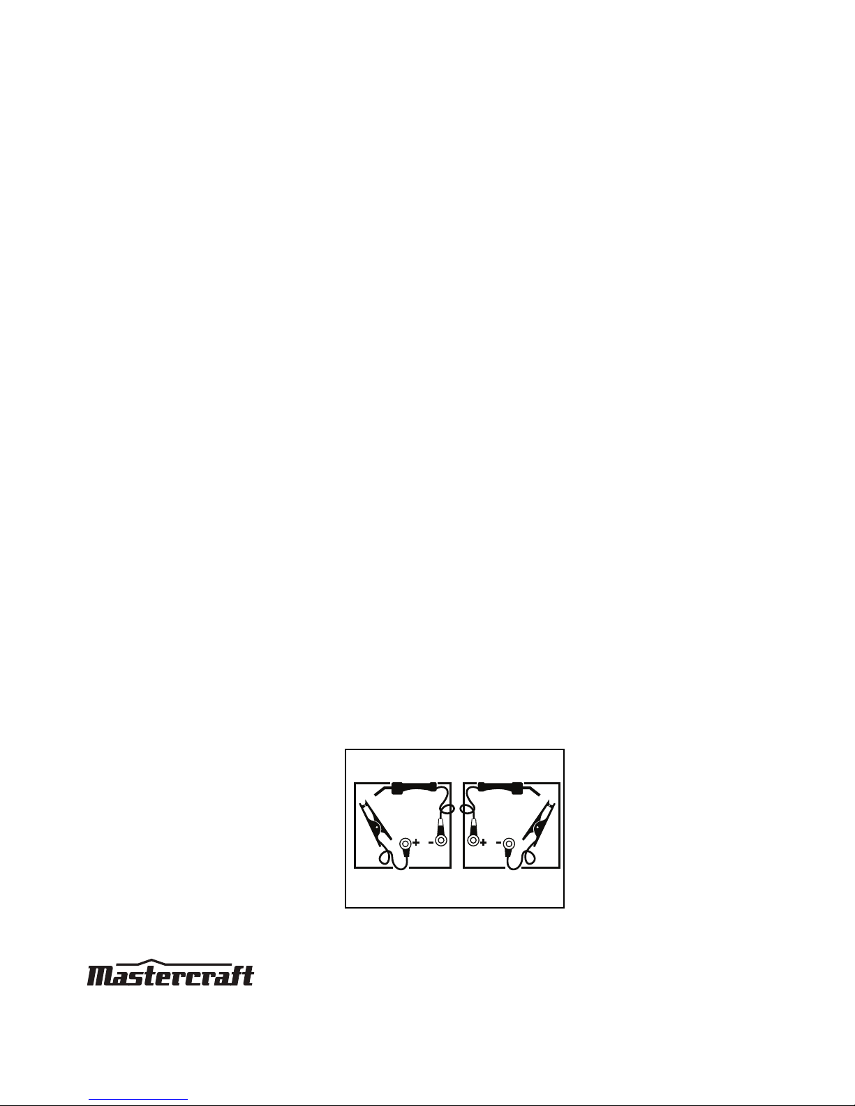
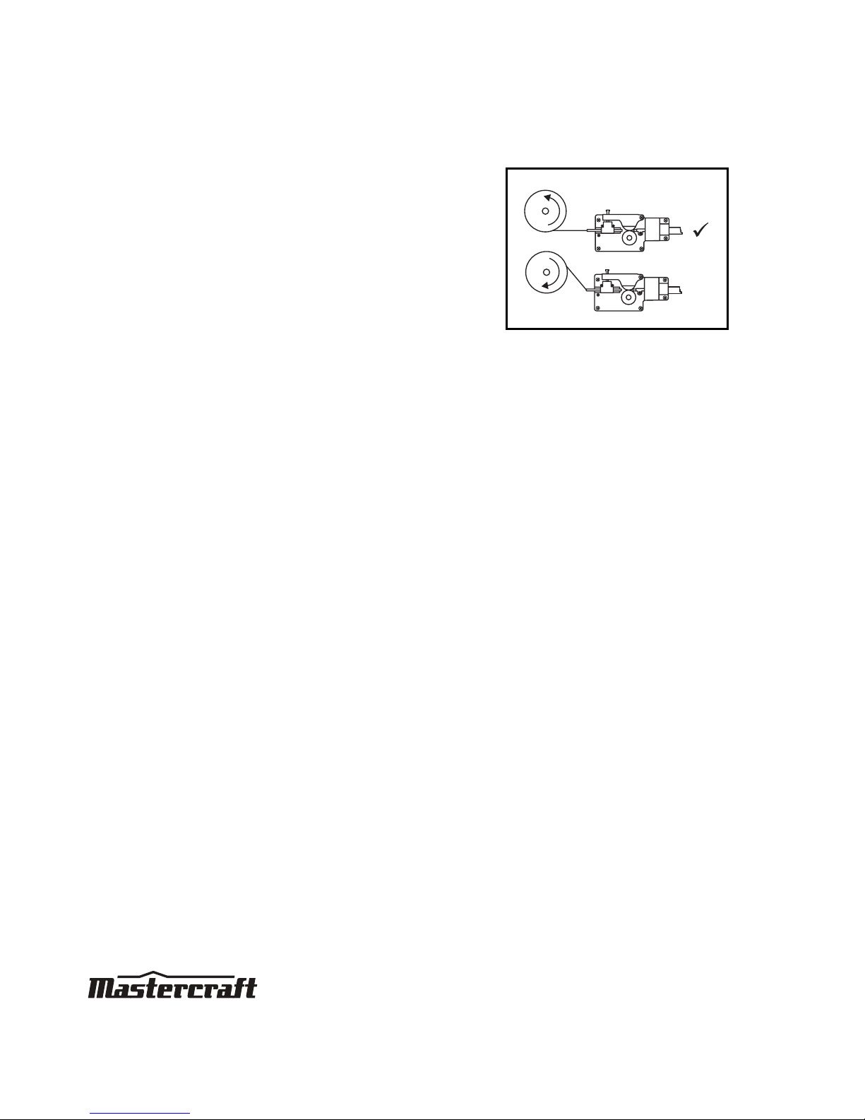
Polarity changing
Factory polarity setting (electrode negative) is for flux core welding (no shielding gas is required). In
this process the RED gun lead is connected to negative ("-") polarity terminal and the ground cable
is connected to the positive ("+") terminal.
For MIG welding (solid wire) using shielding gas, the RED gun lead is connected to positive ("+") and
the ground cable is connected to negative ("-").
NO
GAS
GAS
MC-588195-22
Page 15

IMPORTANT INFORMATION
12
MIG/FLUX-CORE WIRE FEED WELDER KIT 058-8195-2
Gas hoses, regulator and gas cylinder connections
• Connect the gas hose to the gas solenoid valve on the back panel of the welder.
• Connect the other end to the regulator connected to the shielding gas cylinder.
• Slowly open the cylinder valve by turning it counterclockwise until the cylinder pressure gauge
fixes the cylinder pressure.
• Slowly turn the adjustment knob clockwise to increase gas flow to 20 cfm. Turn it
counterclockwise to reduce the gas flow.
• Gas flow can be heard at the end of the gun when the trigger is activated.
Note: If there is no gas flow, harsh arc with excessive spatter will be found and a smooth weld bead
will not be obtained.
Gas selection
Different materials require different shielding gas when MIG welding. Refer to the set up chart inside
the wire drive compartment.
Mild steel: Use 75% Argon and 25% for reduced spatter and reduced penetration for thinner
materials. Use CO
2
for deeper penetration and increased spatter.
Note: Do not use argon gas concentrations higher than 75% on steel. The result will be extremely
poor penetration, porosity, and brittleness of weld.
Stainless steel: Use a mixed gas consisting of Helium, Argon, and CO
2
.
Aluminum or bronze: Use 100% Argon feed compartment.
No. Description No. Description
1 Gas cylinder 5 Regulator
2 Cylinder valve 6 Adjustment knob
3 Cylinder pressure gauge 7 Gas hose
4 Gas flow gauge
Regulator
1
23456 7
MC-588195-23
MACHINE
Page 16

IMPORTANT INFORMATION
13
MIG/FLUX-CORE WIRE FEED WELDER KIT 058-8195-2
Wire drive compartment
The wire drive compartment has wire feed components (1) such as wire feeder and spool hub, and a
set up chart (2).
1 2 3
4 56
MC-588195-25
1
2
Page 17

ASSEMBLY INSTRUCTIONS
14
MIG/FLUX-CORE WIRE FEED WELDER KIT 058-8195-2
Assembly Instructions
Installing the handle:
1. Line up the holes in the handle with the
holes on the top of the welder.
2. Place a lock washer (1) and a washer (2)
onto the welder handle screws.
3. Insert a screw with the washers through
the holes on the handle and into the top
of the welder, and tighten the screw
(fig A)
.
Installing the wire roller:
1. Open the wire drive compartment.
2. Remove the drive tension by loosening
the drive tension adjusting knob (1) and
lifting the drive tension adjustor and
drive tension arm (2) away from the
drive roller
(fig B)
.
3. Put an end of the wire into the hole on
outside edges of the wire spool and
bend it over to hold the wire in place.
Remove the wire spool from the wire
drive compartment.
Note: If the wire is already installed in the welder, roll the wire back onto the wire spool by manually
rotating the wire spool clockwise. Do not allow the wire to come out of rear end of the inlet guide
tube.
2
3
MC-588195-02
fig A
1
fig B
2
1
MC-588195-03
Page 18
ASSEMBLY INSTRUCTIONS
15
MIG/FLUX-CORE WIRE FEED WELDER KIT 058-8195-2
4. Rotate the drive roller cap (1)
counterclockwise and remove it from the
drive roller (2)
(fig C)
.
5. Pull the drive roller (1) from the drive
roller shaft (2)
(fig D)
.
Based on the wire diameter, select the correct groove using the following table:
Note: When installing the drive roller, the number stamped on the drive roller should face the user.
Push the drive roller onto the drive roller shaft.
6. Reinstall the drive roller cap and lock in place by turning it clockwise. Close the wire drive
compartment.
0.6
fig C
1
2
MC-588195-04
1
2
fig D
MC-588195-05
Wire Diameter
Roller Groove
0.023" 0.023"
0.030" 0.030"
0.035" 0.035"
Page 19

ASSEMBLY INSTRUCTIONS
16
MIG/FLUX-CORE WIRE FEED WELDER KIT 058-8195-2
Installing the wire:
Select the type of wire using the following table:
1. Remove the nozzle (1) and contact tip (2)
from the end of the torch assembly
(fig E)
.
2. Ensure proper groove on the drive roller
is in place for the wire to be installed.
3. Remove the packaging from the wire
spool and identify the leading end of the
wire secured on the edge of the spool.
Do not unhook it at this time.
WARNING!
Potential hazard that could result in serious injury or loss of life.
• Always switch off the power and unplug the power cord from the AC power
source before installing the wire.
• Remove any wire or wire spool that is rusty.
• Do not weld metal thinner than 18 gauge, as doing so may burn the metal.
• Before installing, remove any old wire from the MIG gun assembly to prevent
the wire from being jammed inside the gun liner.
• Use extreme caution when removing the welding nozzle, as the contact tip
on the welder is live whenever the torch trigger is pulled.
Wire Type
Availability
0.23" MIG wire Yes
0.30" MIG wire Yes
Flux Core wire 0.030" Yes
Flux Core wire 0.035" Yes
fig E
1
2
MC-588195-06
Page 20
ASSEMBLY INSTRUCTIONS
17
MIG/FLUX-CORE WIRE FEED WELDER KIT 058-8195-2
4. Place the spool on the hub with the
wire passing from the bottom of spool
into the drive mechanism
(fig F)
.
Note: The welder can use either 4" or 8"
spool. The 8" spool requires an adaptor. The
wing nut controls the tension on the spool.
5. Setting the wire spool tension:
a. Turn the wire spool with one hand.
b. Increase the spool tension by tightening the wing nut while turning the spool. Turn the
spool until it slows down.
c. Stop tightening the wing nut. Repeat these steps until proper spool tension is achieved.
Note: If high tension is applied to the wire spool, the wire slips on the drive roller or will not be able
to feed. If less tension is applied, the wire spool unspools itself when the trigger is released.
Readjust the spool tension using the wing nut if the tension is high or low.
6. Disconnect the welder from the power source, and remove the leading end of the wire from
the spool.
7. Cut off any bent portion of the wire using a wire cutter.
8. Loosen the tension adjusting knob holding the drive tension arm in place and lift the tension
arm up off the drive roller.
9. Insert the wire into the inlet guide tube, and feed it of about six inches across the drive roller
and into the torch assembly.
10. Line up the wire with the correct groove in the drive roller.
11. Place the drive tension arm back above the drive roller.
12. Tighten the drive tension adjusting knob until the tension roller is applying enough force on
the wire to prevent it from slipping in the drive roller.
13. Plug in and turn the welder ON. Set the voltage switch to the voltage setting recommended for
the gauge of metal that is to be welded. Refer to the set up chart on the back side of the wire
drive compartment.
14. Set the wire speed control
. Straighten the MIG gun cable and pull the trigger in the gun
handle to feed the wire through the torch assembly
.
X
fig F
MC-588195-07
Page 21

ASSEMBLY INSTRUCTIONS
18
MIG/FLUX-CORE WIRE FEED WELDER KIT 058-8195-2
15. Turn the power switch to the OFF position. Select a contact tip having the diameter same as
the wire being used
.
Note: Due to inherent variances in flux cored welding wire, it is necessary to use a contact tip of size
larger than the wire.
16. Slide the contact tip over the wire, thread the contact tip into the end of the gun and tighten
securely.
17. Install the nozzle on the gun assembly, and cut off excess wire that extends past the end of
the nozzle.
Setting the wire tension:
1. Press the trigger on the gun.
2. Turn the drive tension adjustment knob
(1) clockwise, and increase the drive
tension until the wire seems to feed
smoothly without slipping
(fig G)
.
WARNING!
Potential hazard that could result in serious injury or loss of life.
• Ensure that wire passing out of the end of the torch does not contact with
the workpiece, ground clamp or any grounded material during the drive
tension setting process, as doing so may reduce the risk of arc flash.
MC-588195-24
fig G
1
Page 22

OPERATING INSTRUCTIONS
19
MIG/FLUX-CORE WIRE FEED WELDER KIT 058-8195-2
Operation
Holding the torch (MIG gun):
• While using the welder, experiment holding the torch in different positions until finding a
suitable position.
Distance from the workpiece:
• If the nozzle is held off the workpiece, the distance between the nozzle and the workpiece
should be kept constant and should not exceed ¼".
Tuning in the wire speed:
This is one of the most important parts of the MIG welder operation and must be done before
starting each welding job or whenever any of the following variables are changed: heat setting, wire
diameter, or wire type.
1. Connect the ground clamp to a scrap piece of the same type of the material to be welded.
Note: The thickness of the scrap piece should be equal to or greater than the thickness of the actual
workpiece, and free of oil, paint, and rust.
2. Select the heat setting.
3. Hold the torch in one hand, and allow the nozzle to rest on the edge of the workpiece farther
from the user and at an angle similar to that which will be used when welding.
There are two angles of the torch nozzle in relation to the workpiece that must be considered
when welding.
WARNING!
Potential hazard that could result in serious injury or loss of life.
• Prolonged exposure to the welding arc can cause blindness and burns.
• Never strike the arc or start welding until the user is adequately protected.
• Wear flameproof welding gloves, heavy long sleeved shirt, trousers with out
cuffs, high topped shoes, and welding helmet.
Page 23

OPERATING INSTRUCTIONS
20
MIG/FLUX-CORE WIRE FEED WELDER KIT 058-8195-2
4. Turn the wire speed dial with the other hand to its maximum position and continue to hold
onto the knob.
5. Pull the trigger (1) on the torch to start an arc. Drag the torch toward the user while
simultaneously turning the wire speed dial counterclockwise
(fig J)
.
6. When the wire speed decreases, the sound that the arc makes will change from a sputtering
sound to a high-pitched buzzing sound. The correct setting is the point where the high-pitched
buzzing sound is achieved.
Use the wire feed control to slightly increase or decrease the heat and penetration by
selecting higher or lower wire feed settings. Repeat this tune-in procedure if a new heat
setting, a different diameter wire, or a different type of welding wire is selected.
Angle A Angle B
• Angle A can be varied, but in most
cases the optimum angle will be 60
degrees (the point at which the torch
handle is parallel to the workpiece). If
angle A is increased, penetration will
increase, and if it is decreased
penetration will decrease
(fig H)
.
• Angle B can be varied to improve the
visibility of the arc in relation to the weld
puddle and to direct the force of the arc
(fig I)
.
60
fig H
MC-588195-09
30
45
fig I
MC-588195-10
MC-588195-25
1
fig J
Page 24

OPERATING INSTRUCTIONS
21
MIG/FLUX-CORE WIRE FEED WELDER KIT 058-8195-2
Welding techniques:
• Torch travel: The movement of the torch along the weld joint. For a solid weld bead, the
welding torch should be moved steadily and at the right speed along the weld joint. Moving
the torch too fast, too slow, or erratically prevents proper fusion or creates a lumpy, uneven
bead.
• Travel direction: The direction of the torch moving along the weld joint in relation to the weld
puddle. The torch is either pushed into the weld puddle or pulled away from the weld puddle.
For most welding jobs, pull the torch along the weld joint for greater weld puddle visibility
(fig K)
.
• Travel speed: The rate at which the torch is being pushed or pulled along the weld joint. For a
fixed heat setting, if the travel speed is faster, the penetration will be low and the finished
weld bead will be low and narrow. Likewise, if the travel speed is slow, the penetration will be
deep and the finished weld bead will be high and wide.
WARNING!
Potential hazard that could result in serious injury or loss of life.
• Prolonged exposure to the welding arc can cause blindness and burns.
• Do not perform any welding while standing, kneeling, or lying on the grounded
area. Failure to comply could result in serious injury or loss of life.
fig K
MC-588195-12
Page 25

OPERATING INSTRUCTIONS
22
MIG/FLUX-CORE WIRE FEED WELDER KIT 058-8195-2
Types of welding beads:
Stringer bead Weave bead
• The stringer bead is formed by
travelling with the torch in a straight
line while keeping the wire and nozzle
centered over the weld joint
(fig L)
.
• The weave bead is made by weaving the
wire from side to side while moving with
the torch
(fig M)
.
fig L
MC-588195-13
fig M
MC-588195-14
Page 26
OPERATING INSTRUCTIONS
23
MIG/FLUX-CORE WIRE FEED WELDER KIT 058-8195-2
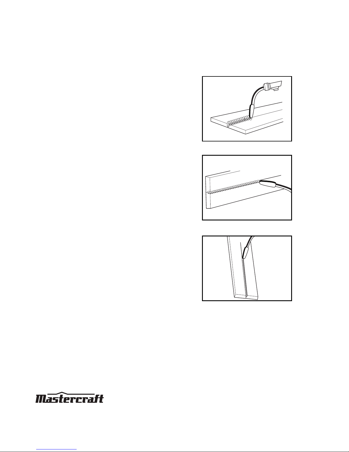
Welding position:
1. Flat position: This position is easiest and
most commonly used. It is best to weld
in the flat position to achieve good
results
(fig N)
.
2. Horizontal position: This position
prevents the weld puddle from running
downward while allowing slow and
enough travel speed. For this position,
angle B should be about 30 degrees
downward from being perpendicular to
the workpiece
(fig O)
.
3. Vertical position: The torch can be easily
pulled from top to bottom in this
position, though it is difficult to prevent
the puddle from running downward.
Pushing the torch from bottom to top
provides better puddle control and
allows slower rates of travel speed to
achieve deeper penetration. For this
position, angle B should be zero and
angle A will vary from 45 to 60 degrees
to provide better puddle control
(fig P)
.
fig N
MC-588195-15
fig O
MC-588195-16
fig P
MC-588195-17
Page 27

OPERATING INSTRUCTIONS
24
MIG/FLUX-CORE WIRE FEED WELDER KIT 058-8195-2
4. Overhead position: This is the most
difficult welding position. For this
position, angle A should be maintained
at 60 degrees
. Maintaining this angle
will reduce falling of molten metal into
the nozzle
(fig Q)
.
Angle B should be zero degrees so that
the wire is aiming directly into the weld
joint. If excessive dripping of the weld
puddle occurs, select a lower heat
setting.
fig Q
MC-588195-18
Page 28

OPERATING INSTRUCTIONS
25
MIG/FLUX-CORE WIRE FEED WELDER KIT 058-8195-2
Multiple pass welding:
• Butt weld joint: When butt welding
thicker materials, prepare the edges of
the material to be joined by grinding a
bevel on the edges of the metal pieces
being joined. When it is done, a "V" is
created between the two metal pieces.
In most cases, more than one pass or
bead will need to be laid into the joint to
close the "V"
(fig R)
.
Note: When using self-shielding flux core wire,
it is necessary to thoroughly chip and brush the
slag off each completed weld bead before
making another pass.
• Fillet weld joint: Most fillet weld joints on
metals of moderate to heavy thickness
will require multiple pass welds to
produce strong joint. The sequence of
lying multiple pass beads into a T fillet
joint and a lap fillet joint is shown
(fig S)
.
fig R
1
2
1
1
23
First or
Root Pass
Second
Pass
Third
Pass
MC-588195-19
Finished
Weld
fig S
1
1
2
3
2
3
Lap Joint Welded
In Three Passes
T Join in
Three Passes
MC-588195-20
Page 29

OPERATING INSTRUCTIONS
26
MIG/FLUX-CORE WIRE FEED WELDER KIT 058-8195-2
Spot welding:
There are three methods of spot welding:
1. Burn-through method: In this method,
two overlapped metal pieces are welded
together by burning through the top
piece and into the bottom piece. The
wire suitable for this method is 0.035
inch self-shielding, flux core wire.
Always select the high heat setting for
this method and tune in the wire speed
prior to making a spot weld
(fig T)
.
Note: Do not use 0.030 inch self-shielding flux
core wires when using this method unless the
metal is very thin or excessive filler metal and
minimal penetration is acceptable.
2. Punch and fill method: This method
produces a weld with the most finished
appearance. In this method, a hole is
punched or drilled into the top piece of
metal and the arc is directed through the
hole to penetrate into the bottom piece.
The puddle is allowed to fill up the hole
leaving a spot weld that is smooth and
flush with the surface of the top piece
(fig U)
.
3. Lap spot method: The welding arc is
directed to penetrate the bottom and top
pieces at the same time, and along each
side of the lap joint seam. Select the
wire diameter, heat setting, and tune in
the wire speed in such a way suitable
for welding the material with a
continuous bead
(fig V)
.
fig T
MC-588195-21
fig U
MC-588195-22
fig V
MC-588195-23
Page 30

OPERATING INSTRUCTIONS
27
MIG/FLUX-CORE WIRE FEED WELDER KIT 058-8195-2
Instructions to be followed for the spot welding methods:
1. Select the wire diameter and heat setting recommended above for the intended method of
spot welding.
2. Tune in the wire speed as if a continuous weld is to be performed.
3. Hold the nozzle piece completely perpendicular to and about ¼ inch off the workpiece.
4. Pull the trigger on the torch and release it when the desired penetration is achieved.
5. Make practice spot welds on scrap metal and vary the duration of time of holding the trigger
until a desired spot weld is made.
6. Make spot welds on the actual workpiece at desired locations.
Page 31

MAINTENANCE
28
MIG/FLUX-CORE WIRE FEED WELDER KIT 058-8195-2
Maintenance
The welder needs regular maintenance as following:
• Clean the dust, dirt, and grease periodically from the welder.
• Every six months, remove the front panel from the welder to clear the accumulated dust and
dirt.
• Replace power cord, ground cable, ground clamp, or electrode assembly when damaged or
worn.
• Repairs must be performed by a qualified service technician only.
Storage
• Store the welder in a clean and dry location away from corrosive gas and excess dust at a
temperature of 10°F
-120°F and relative humidity of less than 90%.
• It is recommended to repack the welder when transporting or storing the welder after use.
• Cleaning is required before storage.
WARNING!
Potential hazard that could result in serious injury or loss of life.
• Unplug the welder before performing any maintenance or service.
• Only use the welder after replacing or repairing any damaged parts or
accessories.
• Use only recommended and properly rated replacement parts. Failure to
comply could lead to serious injury or loss of life.
MAINTENANCE
REQUIRED
DESCRIPTION
TOOLS OR
MATERIALS
REQUIRED
MAXIMUM SERVICE INTERVAL
Each Use or
every 2 Hrs
Monthly
As
Needed
In-depth inspection
Worn or broken
parts
X X
Replace worn or
broken parts
X
Page 32

TROUBLESHOOTING
29
MIG/FLUX-CORE WIRE FEED WELDER KIT 058-8195-2
Troubleshooting
The following chart lists common issues and solutions. Please read it carefully and follow all
instructions closely.
WARNING!
Potential hazard that could result in serious injury or loss of life.
• If any of the following symptoms appears while the welder is in use, turn it off
and disconnect it from the power supply immediately. Failure to heed this
warning will result in serious personal injury or loss of life.
• Repairs must be performed by a qualified service technician only.
PROBLEM POSSIBLE CAUSES SOLUTIONS
The welder does not
work when the main
switch is turned on.
1. No power input.
2. Power cord or power plug is
broken.
3. Main switch is broken.
4. Transformer is broken.
1. Check the circuit or fuse of the power supply.
2. Replace the power cord.
3. Replace the main switch.
4. Replace the transformer.
The welder does not
weld.
1. Incorrect power input.
2. Inadequate current at the output.
3. Poor connection of output cable.
4. Dirty surfaces.
5. Wrong welding wire.
1. Check the power source.
2. Check for proper grounding to the workpiece.
3. Check the output connection.
4. Clean the surfaces.
5. Use the correct wire.
If the problem persists, send it for servicing or
return back to the store.
Blown fuse or
tripped circuit
breaker.
Inadequate fuse or circuit breaker. Check whether the fuse in power supply is 20 A.
If the problem persists, send it for servicing or
return back to the store.
Arc is hard to start.
1. Wrong welding wire.
2. Base metal not grounded
properly.
1. Use the correct wire.
2. Make sure the connection is good.
If the problem persists, send it for servicing or
return back to the store.
Page 33

TROUBLESHOOTING
30
MIG/FLUX-CORE WIRE FEED WELDER KIT 058-8195-2
Note: For further repair information, please call 1-800-689-9928.
Inconsistent arc or
wire feed.
1. Not enough drive roller pressure.
2. Spool hub tension too tight or
loose.
3. Contact tip worn or wrong size.
4. Rusty or corroded wire.
1. Tighten the drive tension adjustor on wire
feeder.
2. Adjust the wing nut on the spool holder.
3. Replace the contact tip.
4. Replace the wire.
PROBLEM POSSIBLE CAUSES SOLUTIONS
Page 34
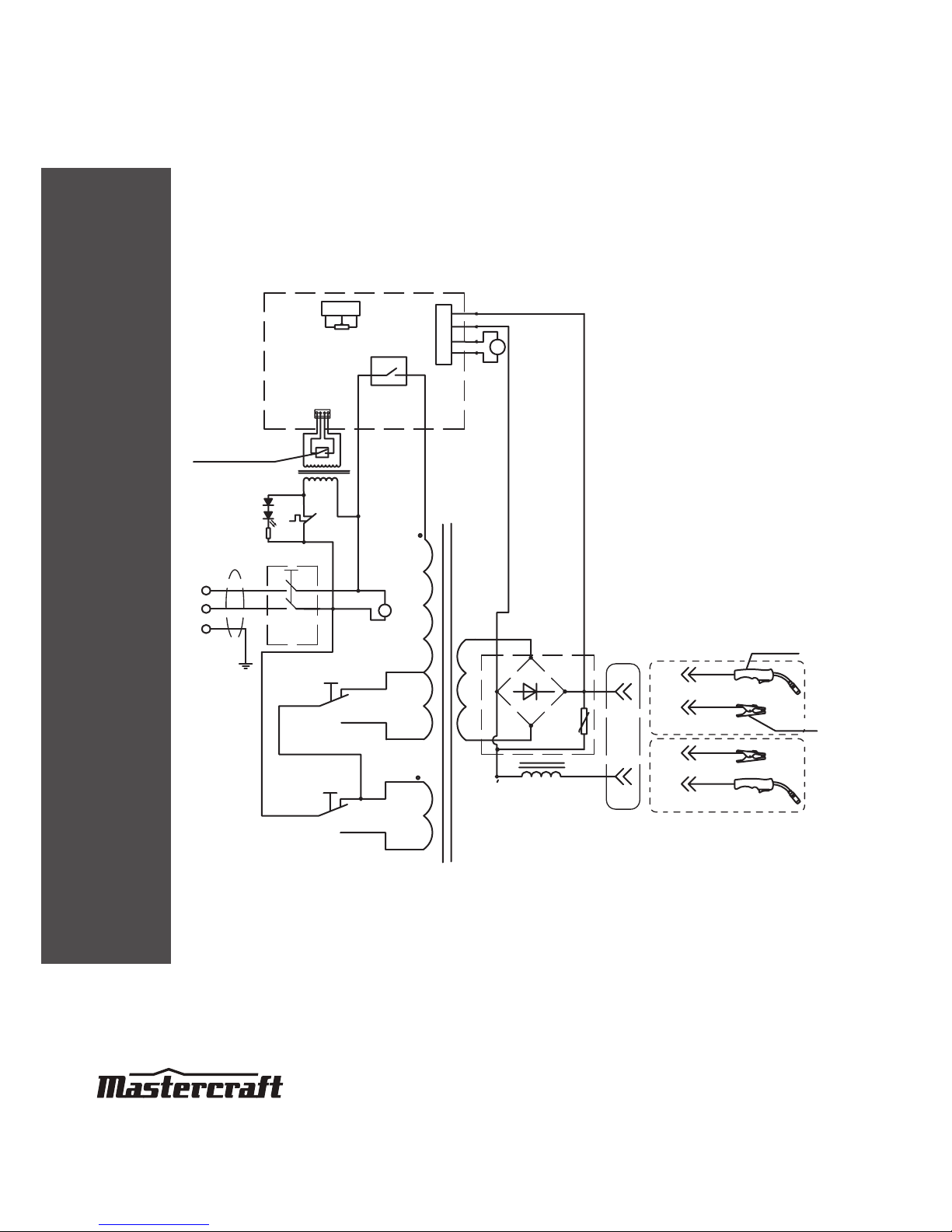
MAIN CIRCUIT CHART
31
MIG/FLUX-CORE WIRE FEED WELDER KIT 058-8195-2
Welding gun switch
Welding gun
2
3
4
5
2
1
2
1
+
_
_
+
+
+
_
_
223
34
1
1
S1
T1
J
G
L
S2
S3
PCB
MAX
fan
TR1
24V
MIN
+
_
NO GAS
GAS
Earth champ
MC-588195-24
Page 35

EXPLODED VIEW
32
MIG/FLUX-CORE WIRE FEED WELDER KIT 058-8195-2
28
1
4
8
9
6
7
31
12
34
37
27
26
25
22
21
20
19
24
23
10
29
32
33
35
36
2
3 5
11
13
14
18
15
16
17
30
MC-588195-25
Page 36

PARTS LIST
33
MIG/FLUX-CORE WIRE FEED WELDER KIT 058-8195-2
If any parts are missing or damaged, or if you have any questions, please call 1-800-689-9928.
No. Description Qty. No. Description Qty.
1 Ground cable and clamp 1 20 Cable holder 1
2 Wire feed setting knob 1 21 Back panel 1
3 Torch cable holder 1 22 Gas hose connector 1
4 Cable holder 1 23 Rectifier 1
5 Front panel 1 24 Rectifier bracket 1
6 PCB support 1 25 Vertical middle panel 1
7 PCB 1 26 Spool holder 1
8 Bottom 1 27 Plastic hinge 2
9 Feet 1 28 Left panel 1
10 Control transformer 4 29 Fuse 1
11 Thermal relay 1 30 Red terminal 1
12 Circuit breaker 1 31 Black terminal 1
13 Main transformer 1 32 Door bolt 1
14 Fan bracket 1 33 Wire feeder 1
15 Fan 2 34 MIN/MAX 1/2 voltage switch 2
16 Fan blade 1 35 ON/OFF switch 1
17 Handle 1 36 Overload indicator 1
18 Right panel 1 37 MIG torch 1
19 Power cord 1
Page 37

WARRANTY
34
MIG/FLUX-CORE WIRE FEED WELDER KIT 058-8195-2
Mastercraft® limited warranty
This warranty is subject to the following conditions and limitations:
a. A bill of sale verifying the purchase and purchase date must be provided.
b. This warranty will not apply to any product or part thereof which is worn or broken or which
has become inoperative due to abuse, misuse, accidental damage, neglect, or lack of proper
installation, operation, or maintenance (as outlined in the applicable instruction manual or
operating instructions), or which is being used for industrial, professional, commercial, or
rental purposes.
c. This warranty will not apply to normal wear and tear or to expendable parts or accessories
that may be supplied with the product which are expected to become inoperative or unusable
after a reasonable period of use.
d. This warranty will not apply to routine maintenance and consumable items such as, but not
limited to, fuel, lubricants, vacuum bags, blades, belts, sandpaper, bits, fluids, tune-ups, or
adjustments.
e. This warranty will not apply where damage is caused by repairs made or attempted by others
(i.e., persons not authorized by the manufacturer).
f. This warranty will not apply to any product that was sold to the original purchaser as a
reconditioned or refurbished product (unless otherwise specified in writing).
g. This warranty will not apply to any product or part thereof if any part from another
manufacturer is installed therein or any repairs or alterations have been made or attempted by
unauthorized persons.
This Mastercraft
®
product is guaranteed for a period of
three (3) years from the date of original retail purchase
against defects in workmanship and materials.
Subject to the conditions and limitations described below,
this product, if returned to us with proof of purchase within
the stated warranty period and if covered under this
warranty, will be repaired or replaced (with the same model,
or one of equal value or specification), at our option. We will
bear the cost of any repair or replacement and any costs of
labor relating thereto.
Page 38

WARRANTY
35
MIG/FLUX-CORE WIRE FEED WELDER KIT 058-8195-2
h. This warranty will not apply to normal deterioration of the exterior finish, such as, but not
limited to, scratches, dents, paint chips, or to any corrosion or discoloring by heat, or abrasive
and chemical cleaners.
i. This warranty will not apply to component parts sold by and identified as the product of
another company, which shall be covered under the product manufacturer’s warranty, if any.
Additional limitations
This warranty applies only to the original purchaser and may not be transferred. Neither the retailer
nor the manufacturer shall be liable for any other expense, loss, or damage, including, without
limitation, any indirect, incidental, consequential, or exemplary damages arising in connection with
the sale, use, or inability to use this product.
Notice to consumer
This warranty gives you specific legal rights, and you may have other rights, which may vary from
province to province. The provisions contained in this warranty are not intended to limit, modify, take
away from, disclaim, or exclude any statutory warranties set forth in any applicable provincial or
federal legislation.
 Loading...