

Page 1
Please read and save these instructions. Read carefully before attempting to assemble, install, operate or maintain the product described.
Protect yourself and others by observing all safety information. Failure to comply with instructions could result in personal injury and/or
property damage! Retain instructions for future reference.
Operating Instructions and Parts Manual WS0973, 58-8023-2
Arc Welder
Description
This Mastercraft Arc Welder is designed to
be used on standard 115 V household
current. It is equipped with an output
control to accurately select the proper
current needed for various welding
conditions. Internal components are
thermostatically protected.
This welder can weld up to 1/8” steel in a
single pass. Recommended electrode size
is 1/16” diameter for 15 A circuits, up to
5/64” diameter for 20 A circuits. For
replacement electrodes, call 1-866-2202097 for the nearest authorized service
centre.
Unpacking
When unpacking, inspect carefully for any
damage that may have occurred during
transit. Report any damaged or missing
items by calling 1-866-220-2097.
Circuit Requirements
This equipment
requires a
dedicated 115 V circuit. Refer to the
following chart for the correct circuit
breaker or fuse rating. Do not run other
appliances, lights, or tools on this
circuit while operating this equipment.
Extension cords are not recommended.
Blown fuses or tripped circuit breakers
can result from failure to comply with
this recommendation.
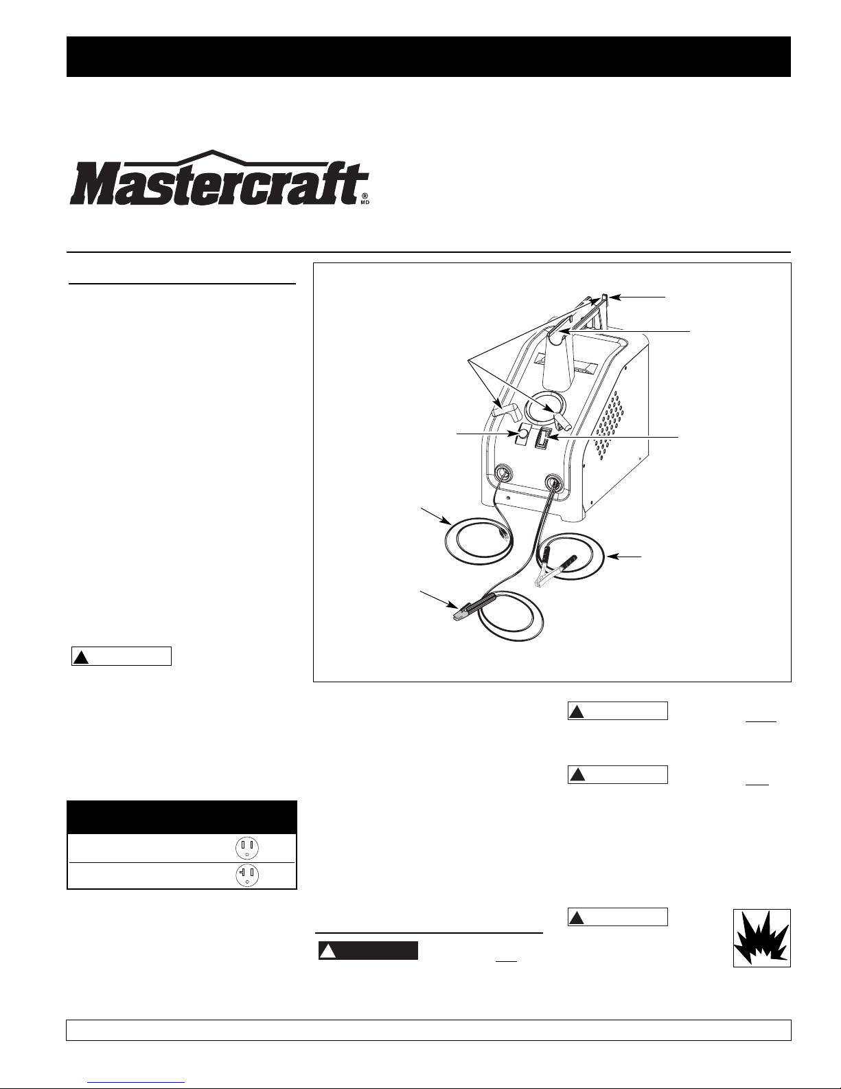
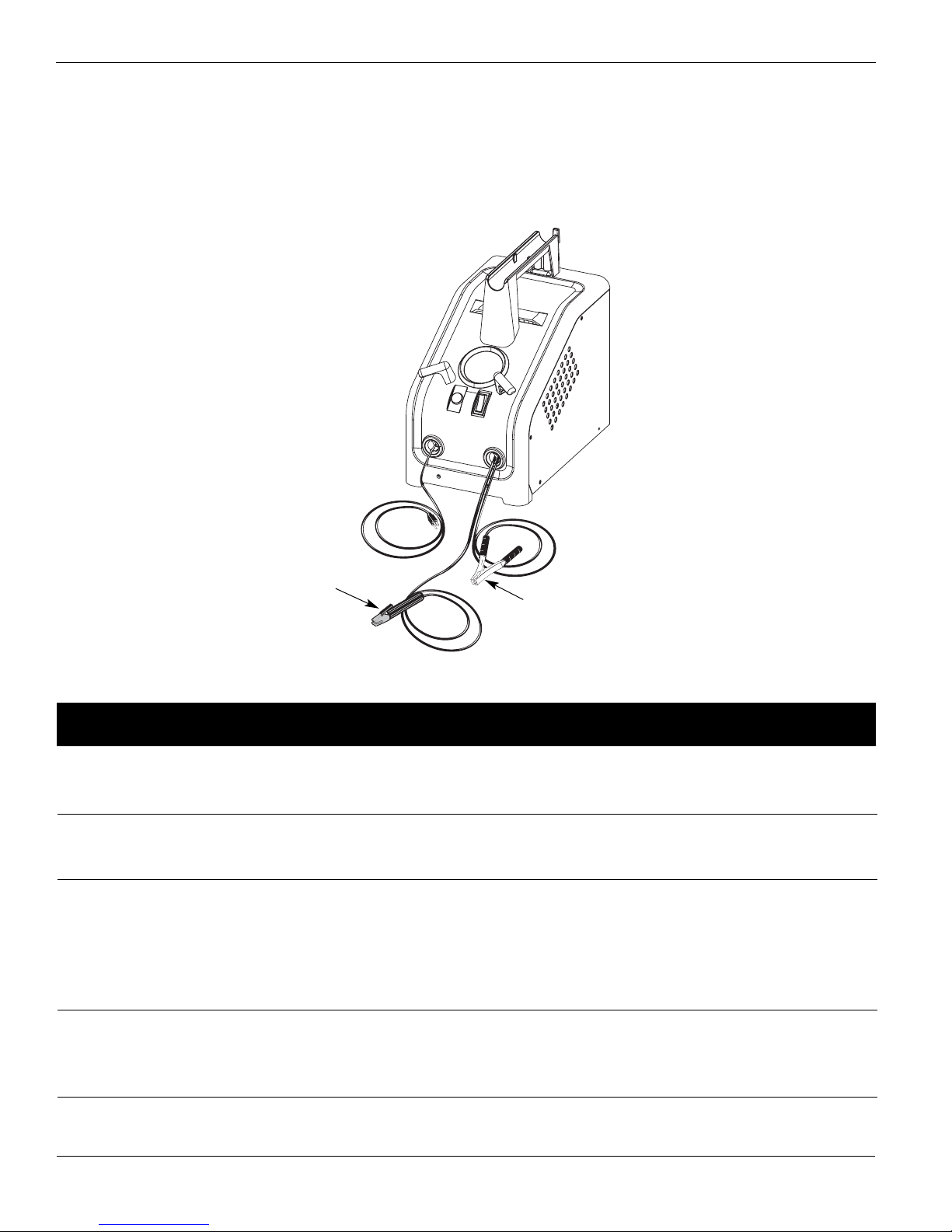
Components and Controls
1. Work Clamp- connect to workpiece
2. Electrode Holder - holds electrode
welding rod
3. Power Cord - plug into 115 V outlet.
4. Power Switch - High/Off/Low.
5. Indicator Light - light activates if
thermostat has automatically shut unit
off.
6. Hand-shield hook - for hanging the
hand-shield for storage and transport.
7. Cable Keepers - for wrapping the
cables during storage and transport.
8. Storage Pocket - for storing the
chipping hammer/brush. Also can be
used for storing a tube of welding
rods.
General Safety
Danger means a
hazard that will
cause death or serious injury if the
warning is ignored.
Warning means a
hazard that could
cause death or serious injury if the
warning is ignored.
Caution means a
hazard that may
cause minor or moderate injury if the
warning is ignored. It also may mean a
hazard that will only cause damage to
property.
NOTE: Note means any additional
information pertaining to the product
or its proper usage.
Always keep a fire
extinguisher accessible
while performing arc
welding operations.
Figure 1 - Welder Components and Controls
IN972300AV 7/04
Low 15 A
High 20 A
Heat Circuit Breaker or
Setting Slow Blow Fuse
1
2
3
4
5
6
7
REMINDER: Keep your dated proof of purchase for warranty purposes! Attach it to this manual or file it for safekeeping.
8
!
CAUTION
!
DANGER
!
WARNING
!
CAUTION
!
WARNING
Page 2
2
Arc Welder
General Safety
(Continued)
Before starting or servicing any
electric arc welder, read and
understand all instructions. Failure
to follow safety precautions or
instructions can cause equipment
damage and or serious personal
injury or death.
All installation, maintenance, repair
and operation of this equipment
should be performed by qualified
persons only in accordance with
national, provincial, and local codes.
Improper use of electric arc
welders can cause electric
shock, injury, and death!
Take all precautions
described in this manual to reduce the
possibility of electric shock.
Verify that all components of the
arc welder are clean and in good
condition prior to operating the
welder. Be sure that the insulation
on all cables, electrode holders, and
power cords is not damaged.
Always repair or replace damaged
components before operating the
welder. Always keep welder panels,
shields, etc. in place when operating
the welder.
Always wear dry protective clothing
and welding gloves, and insulated
footwear.
Always operate the welder in a
clean, dry, well-ventilated area. Do
not operate the welder in humid,
wet, rainy, or poorly ventilated
areas.
Be sure that the workpiece is
properly supported and grounded
prior to beginning any electric arc
welding operation.
Coiled welding cable should be spread
out before use to avoid overheating
and damage to insulation.
Never immerse the
electrode or
electrode holder in water. If the welder
becomes wet for any reason, be
absolutely certain that it is completely
clean and dry prior to attempting use!
Always shut the equipment off and
unplug the power prior to moving
the unit.
Always attach the work lead first.
Verify that the workpiece is securely
grounded.
Always shut off electric arc welding
equipment when not in use and
remove the electrode from the holder.
Never allow any part of the body to
touch the electrode and ground or
grounded workpiece at the same time.
Awkward welding conditions and
positions can be electrically hazardous.
When crouching, kneeling or at
elevations, be sure to insulate all
conductive parts, wear appropriate
protective clothing, and take
precautions to prevent injury from falls.
Never attempt to use this
equipment at current settings or
duty-cycles higher than those
specified on the equipment labels.
Never use an electric arc welder to
thaw frozen pipes.
Flying sparks and hot metal
can cause injury. As welds
cool, slag can be thrown off.
Take all precautions described in this
manual to reduce the possibility of
injury from flying sparks and hot metal.
Wear ANSI approved face shield or
safety glasses with side shield
protection when chipping or
grinding metal parts.
Wear ear plugs when welding
overhead to prevent spatter or slag
from falling into ears.
Electric arc welding
operations produce intense
light and heat and ultraviolet
(UV) rays. This intense light and UV rays
can cause injury to eyes and skin. Take
all precautions described in this manual
to reduce the possibility of injury to
eyes and skin.
All persons operating this
equipment or in the area while
equipment is in use must wear
protective welding gear including:
welding helmet or shield with at
least shade 10, flame resistant
clothing, leather welding gloves,
and full foot protection.
Never look at arc
welding operations
without eye protection as described
above. Never use a shade filter lens
that is cracked, broken, or rated below
number 10. Warn others in the area not
to look at the arc.
Electric arc welding
operations cause sparks and
heat metal to temperatures
that can cause severe burns! Use
protective gloves and clothing when
performing any metal working
operation. Take all precautions
described in this manual to reduce the
possibility of skin and clothing burns.
Make sure that all persons in the
welding area are protected from
heat, sparks, and ultraviolet rays.
Use additional face shields and
flame resistant barriers as needed.
Never touch workpieces until
completely cooled.
Heat and sparks produced
during electric arc welding
and other metal working
operations can ignite
flammable and explosive materials!
Take all precautions described in this
manual to reduce the possibility of
flames and explosions.
Remove all flammable materials
within 35 feet (10.7 metres) of
welding arc. If removal is not
possible, tightly cover flammable
materials with fire proof covers.
Do not operate any electric arc
welder in areas where flammable or
explosive vapours may be present.
Take precautions to be sure that
flying sparks and heat do not cause
flames in hidden areas, cracks,
behind bulkheads, etc.
Fire hazard! Do not weld on
containers or pipes that
contain or have contained
flammable materials or gaseous or
liquid combustibles.
Arc welding closed cylinders
or containers such as tanks
or drums can cause
!
WARNING
!
DANGER
!
WARNING
!
WARNING
!
WARNING
!
WARNING
!
WARNING
!
WARNING
!
WARNING
Page 3
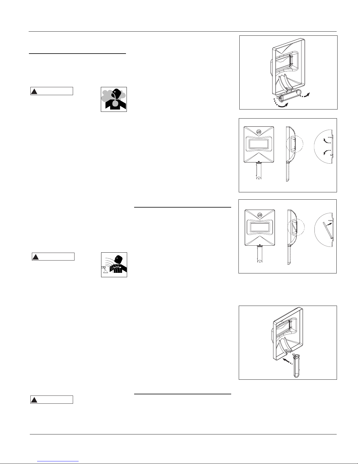
2. Insert filter lens.
3. To attach the handle, place shield on
a flat surface and press handle into
place (See Figure 5).
NOTE: If you have never welded before
or have little experience, a full face
helmet is recommended. Both hands
are needed to stabilize and control the
angle and arc length of the electrode.
General Safety
(Continued)
explosion if not properly vented!
Verify that any cylinder or container to
be welded has an adequate ventilation
hole, so that expanding gases can be
released.
Do not breathe fumes that
are produced by the arc
welding operation. These
fumes are dangerous. If the welding
area cannot be adequately ventilated,
be sure to use an air-supplied
respirator.
Keep the head and face out of the
welding fumes.
Do not perform electric arc welding
operations on metals that are
galvanized or cadmium plated, or
contain zinc, mercury, or beryllium
without completing the following
precautions:
a. Remove the coating from the
base metal.
b. Make sure that the welding area
is well-ventilated.
c. Use an air-supplied respirator.
Extremely toxic fumes are created
when these metals are heated.
The electromagnetic field
that is generated during arc
welding may interfere with
the operation of various electrical and
electronic devices such as cardiac
pacemakers. Persons using such devices
should consult with their physician
prior to performing any electric arc
welding operations.
Route the electrode and work
cables together and secure with
tape when possible.
Never wrap arc welder cables
around the body.
Always position the electrode and
work leads so that they are on the
same side of the body.
Exposure to electromagnetic fields
during welding may have other
health effects which are not known.
Always be sure
that the welding
area is secure and free of hazards
(sparks, flames, glowing metal or slag)
prior to leaving. Be sure that
3
WS0973, 58-8023-2
equipment is turned off and electrode
is removed. Be sure that cables are
loosely coiled and out of the way. Be
sure that all metal and slag has cooled.
ADDITIONAL SAFETY STANDARDS
Code for Safety in Welding and
Cutting
CSA Standard W117.2, from Canadian
Standards Association, Standards Sales,
178 Rexdale Boulevard, Rexdale,
Ontario, Canada M9W 1R3
ANSI Standard Z49.1 from American
Welding Society, 550 N.W. LeJune Rd.
Miami, FL 33126
Safe Practices For Occupational And
Educational Eye And Face
Protection
ANSI Standard Z87.1, from American
National Standards Institute, 1430
Broadway, New York, NY 10018
Refer to the Material Safety Data
Sheets and the manufacturers
instructions for metals, electrodes,
coatings and cleaners.
Installation
Location
Selecting the proper location can
significantly increase performance,
reliability and life of the arc welder.
For best results locate the welder in
an environment that is clean and
dry. Dust and dirt in the welder
retain moisture and increase wear
of moving parts.
Store electrodes in a clean, dry
location with low humidity to
preserve the flux coating.
The receptacle used for the welder
must be properly grounded and the
welder must be the only load on the
power supply circuit. Refer to the
Circuit Amperage chart on page 1
for correct circuit capacity.
The use of an extension cord is not
recommended for arc welding
machines. Extension cord use will
significantly degrade the
performance of the welder.
Assembly
HANDSHIELD
1. Cut detachable handle away from
shield. Trim the excess plastic to
remove sharp edges.
Figure 2
Figure 3
Figure 4
Figure 5
!
WARNING
!
WARNING
!
WARNING
Page 4

The electrode
holder and rod are
electrically “live” (current potential)
when the welder is on.
Grounding against
any metallic
surface may produce an arc which could
cause sparks and damage eyesight.
6. Hold the electrode away from the
grounded workpiece or workbench.
Turn on the welder to either High
or Low. Refer to the following chart
for proper output setting.
7. Position the electrode to begin
weld, lower the welding helmet or
position the hand shield, and strike
an arc. Adjust output setting as
needed.
8. When finished welding, turn welder
off and store properly.
DUTY-CYCLE / THERMOSTATIC
PROTECTION
Welder duty-cycle is the percentage of
actual weld time that can occur in a
ten minute interval. For example, at a
10% duty-cycle, actual welding can
occur for one minute, then the welder
must cool for nine minutes.
Internal components of this welder are
protected from overheating with an
automatic thermal switch. A yellow
lamp is illuminated on the front panel
if the duty-cycle is exceeded. Welding
operations may continue when the
yellow lamp is no longer illuminated.
4
Arc Welder
Operation
1. Be sure to read,
understand, and comply
with all precautions in the
General Safety
Information section. Be sure to read
the entire section entitled Welding
Guidelines prior to using this
equipment.
2. Turn welder off and plug into
appropriate receptacle:
115 V 15 A - Low
115 V 20 A - High
3. Verify that the surfaces of metals to
be joined are free from dirt, rust,
paint, oil, scale or other contaminants.
These contaminants make welding
difficult and cause poor welds.
All persons
operating this
equipment or in the area while
equipment is in use must wear
protective welding gear including: eye
protection with minimum shade 10
lens, flame resistant clothing, leather
welding gloves, and full foot
protection.
If heating, welding, or
cutting materials that are
galvanized, zinc plated, lead, or
cadmium plated refer to the General
Safety Information Section for
instructions. Extremely toxic fumes are
created when these metals are heated.
4. Connect the work clamp to the
workpiece. Make sure the contact is
on bare metal and not obstructed
by paint, varnish, corrosion, or nonmetallic materials.
5. Insert the exposed part of the
electrode rod (the end with no flux)
into the jaws of the electrode
holder.
Maintenance
Disconnect power
supply and turn
machine off before inspecting or
servicing any components.
Before every use:
1. Check condition of weld cables and
immediately repair or replace any
cables with damaged insulation.
2. Check condition of power cord and
immediately repair or replace any
cord if damaged.
3. Check condition of electrode holder
insulating pieces and immediately
replace cracked or missing
insulators. Verify that all fasteners
are tight and insulated.
Do not operate this
welding machine
with cracked or missing insulation on
welding cables, electrode holder, or
power cord.
Every 3 months:
Replace any unreadable labels on the
welder. Use compressed air to blow all
dust and lint from the ventilation
openings.
Electrode Output
Diameter Setting
1/16" (1.6 mm) Low
5/64" (2 mm) High
!
WARNING
!
WARNING
MANUAL
!
WARNING
!
WARNING
!
WARNING
!
WARNING
Page 5
5
Welding Guidelines
General
This welding machine utilizes a process
known as Shielded Metal-Arc Welding
(SMAW). This process is used to bond
metals by heating them with an electric
arc created between the electrode and
the workpiece.
Electrodes used for shielded metal arc
welding have two parts. The inner core is
a metal rod or wire that should be similar
in composition to the base metal. The
outer coating is called flux. Various types
of flux exist. Each coating is used for a
particular welding situation.
While the metal is molten, it can be
contaminated by elements in the air. This
contamination could weaken the weld.
The flux coating creates a protective
barrier called slag that protects the
molten metal from contaminants.
When current (amperage) flows through
the circuit to the electrode, an arc is
formed between the end of the electrode
and the workpiece. The arc melts the
electrode and the workpiece. The melted
metal of the electrode flows into the
molten crater and forms a bond with the
workpiece as shown in Figure 6.
NOTE: Discontinue using and discard
electrodes that burn down to 1 to 2
inches from the electrode holder.
STRIKING AN ARC
Attach work clamp to workpiece. The
jaws of the work clamp must make good
contact with clean bare metal of the
workpiece for good welding results.
Place the bare end of the electrode in the
holder. Grip the holder lightly to reduce
tiring of the hand and arm.
NOTE: Always keep the jaws of the
holder clean to ensure good electrical
contact with the electrode.
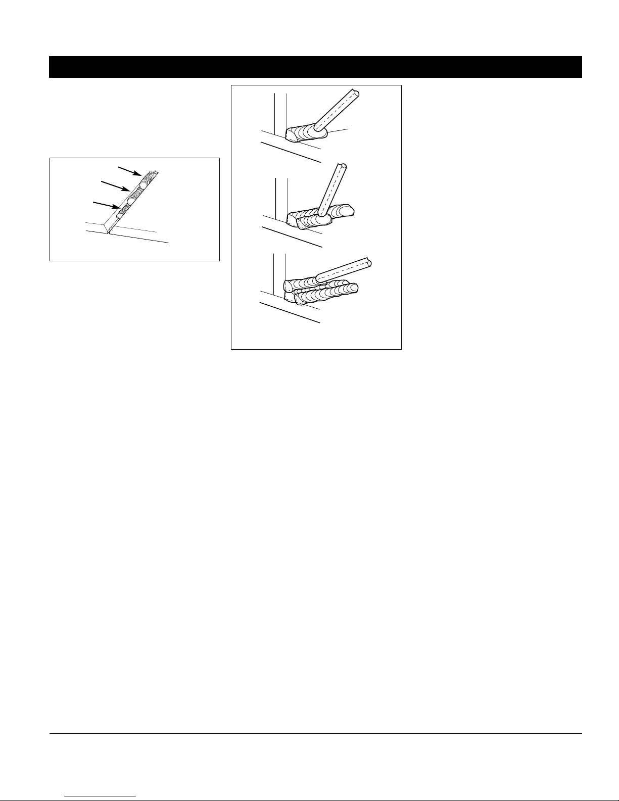
Be careful not to
touch the workpiece
or welding bench with the electrode as
this causes arc flashes.
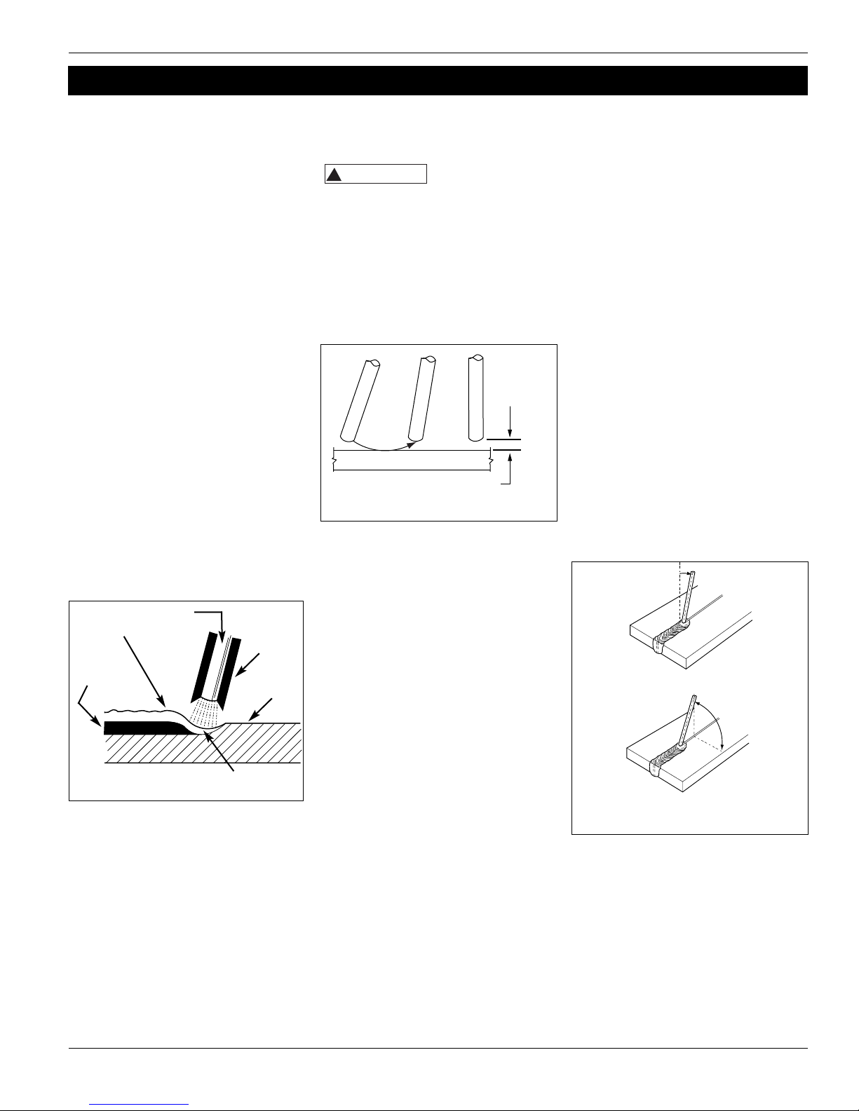
The best method of striking an arc is the
scratching method. Drag the electrode at
an angle along the surface much like
striking a match. Upon contact with the
plate, lift the electrode approximately
1/16” off the surface or it will stick (See
Figure 7).
NOTE: Should the electrode stick to the
workpiece, break it loose by quickly
twisting or bending at the holder while
pulling upward. If the electrode does not
break loose, disengage the electrode by
releasing it from the holder.
ELECTRODE TYPE AND SIZE
Two types of electrodes are
recommended for this welder. The
electrodes are designated as follows:
1. E-6013 GENERAL PURPOSE
• All position, smooth deposit rod with
low spatter.
• For all mild steel and general purpose
work.
2. E-7014 FAST FILL
• Smooth bead and fast deposition
• Ideal for joints with poor fitup and
general repair work
NOTE: E-6011 and E-7018 are not
recommended for use with these
welders. Recommended electrode
diameter is 1/16” or 5/64”. Call
1-866-220-2097 for availability.
Arc Welding Basics
Four basic techniques affect weld
quality. These are: amperage setting,
weld angle, arc length, and travel
speed. Proper use of these techniques is
necessary for good weld quality.
AMPERAGE SETTING
The correct amperage involves the
adjustment of the welding machine to
the required amperage setting. This is
regulated by selecting the appropriate
high or low setting. The amperage
required depends on the size
(diameter) of electrode used and the
thickness of the workpiece.
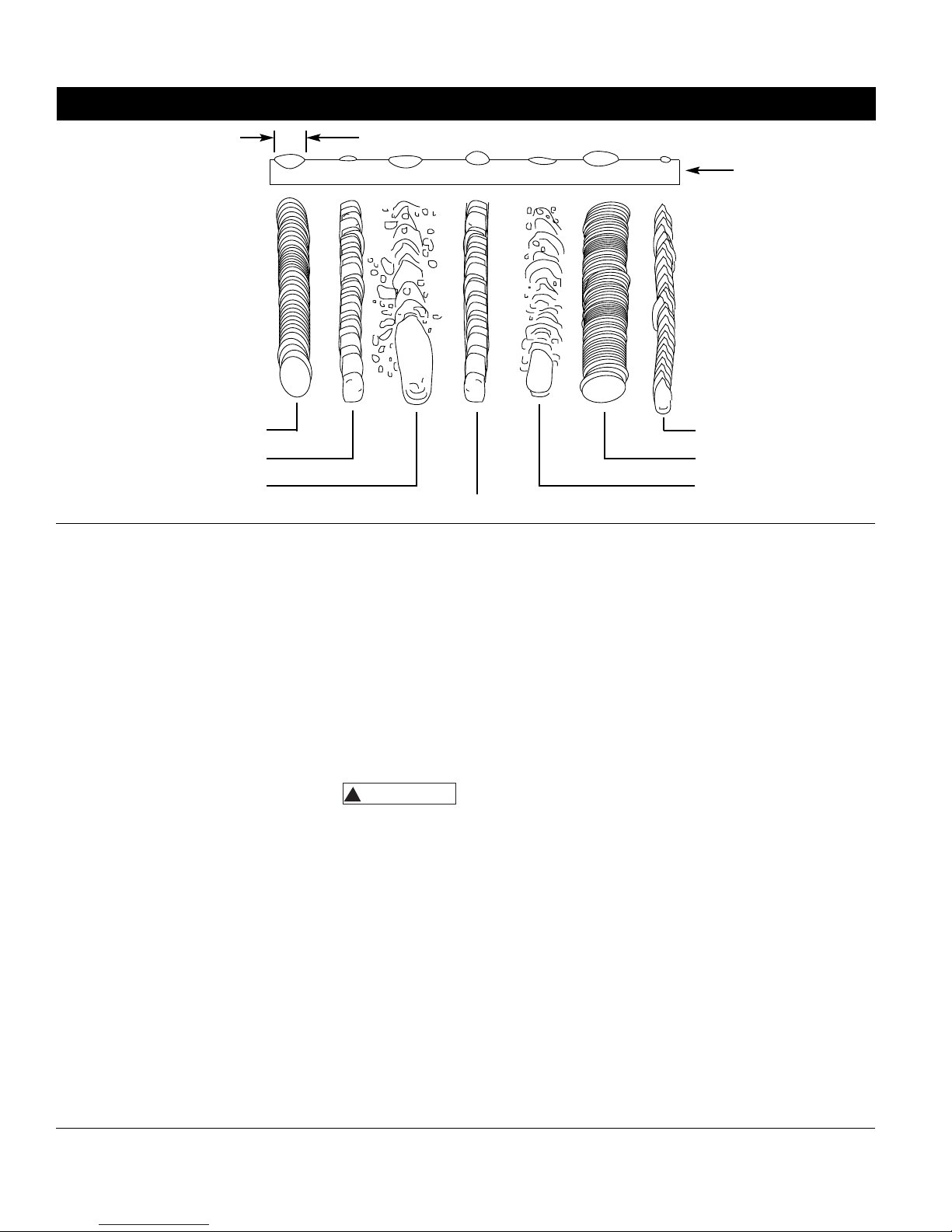
Excessive currents burn through light
metals and the weld bead is flat and
porous (See Figure 9). The bead
appears high and irregular if the
current is too low.
WELD ANGLE
Weld angle is the angle at which the
electrode is held during the welding
process. Using the correct angle ensures
proper penetration and bead formation.
Electrode angle involves two positions travel angle and work angle (See Figure
8).
Travel angle is the angle in the line of
welding and may vary from 5º to 45º
from the vertical, depending on
welding conditions.
Work angle is the angle from
horizontal, measured at right angles to
the line of welding.
For most applications, a 45º travel
angle and 45º work angle is sufficient.
For specific applications, consult an arc
welding handbook.
Slag
Weld
Wire
Flux
Workpiece
Crater
Figure 6 - Weld Components
Same as Electrode Diameter
Figure 7 - Scratching Method
WS0973, 58-8023-2
Figure 8 - Weld Angle
5o - 45
o
Travel Angle
Work Angle
!
WARNING
1/16"
Page 6
6
Arc Welder
NOTE: Right handed welders should
weld from left to right. Left handed
welders should weld from right to left.
The electrode should always point into
the weld puddle as shown.
ARC LENGTH
Arc length is the distance from the
workpiece to the tip of the electrode,
the distance which the arc must travel.
A proper arc length is essential to
generate the heat needed for welding
(See Figure 9). An arc that is too long
produces an unstable arc, reduces
penetration, increases spatter, and
causes flat and wide beads. Too short
an arc does not create enough heat to
melt the workpiece, the electrode has a
tendency to stick, penetration will be
poor, and uneven beads with irregular
ripples result. A proper arc should be
no longer than the diameter of the rod.
The sound of a proper arc is a steady,
crisp sizzle, similar to bacon frying.
TRAVEL SPEED
The travel speed is the rate at which
the electrode is moved across the weld
area (See Figure 9). When the speed is
too fast, the bead is narrow and bead
ripples are pointed as shown. When the
speed is too slow, the weld metal piles
up and the bead is high and wide. To
control travel speed, watch the width
of the weld bead (not the arc) when
welding. The weld bead is the orange,
molten metal behind the arc. The width
should be approximately twice the
diameter of the welding rod. Control
travel speed to obtain a consistent
bead width.
SLAG REMOVAL
Wear ANSI
approved safety
glasses (ANSI Standard Z87.1) and
protective clothing when removing
slag. Hot, flying debris can cause
personal injury to anyone in the area.
After completing the weld, wait for the
welded sections to cool. A protective
coating called slag now covers the weld
bead which prevents contaminants in
the air from reacting with the molten
metal. Once the weld cools to the point
that it is no longer glowing red, the
slag can be removed. Removal is done
with a chipping hammer. Lightly tap
the slag with the hammer and break it
loose from the weld bead. The final
clean-up is done with a wire brush.
When making multiple weld passes,
remove the slag between each pass.
WELDING POSITIONS
Four basic welding positions can be used;
flat, horizontal, vertical, and overhead.
Welding in the flat position is easier than
any of the others because welding speed
can be increased, the molten metal has
less tendency to run, better penetration
can be achieved, and the work is less
fatiguing.
Other positions require different
techniques such as a weaving pass,
circular pass, and jogging. A higher skill
level is required to complete these welds.
All work should be performed in the
flat position if possible. For specific
applications, consult an arc welding
handbook.
WELD PASSES
Sometimes more then one pass is
necessary to fill the joint. The root pass
is first, followed by filler passes and the
Welding Guidelines (Continued)
Normal Amperage,
Arc Length, Speed
Amperage Too Low
Amperage Too High
Arc Length Too Short
Arc Length Too Long
Speed Too Slow
Speed Too Fast
Workpiece
NOTE: Weld bead width (W)
should be approximately
twice the diameter fo the
electrode rod used.
W
Figure 9 - Weld Appearance
!
WARNING
Page 7
7
Welding Guidelines (Continued)
cover pass (See Figure 10). If the pieces
are thick, it may be necessary to bevel
the edges that are joined at a 60º
angle. Remember to remove the slag
between each pass.
Figure 10 - Weld Passes
Cover
Filler
Root
Figure 11 - Multiple Weld Passes
WS0973, 58-8023-2
Page 8

8
Troubleshooting Chart - Welder
Symptom Possible Cause(s) Corrective Action
1. No power at receptacle
2. Broken or damaged power
cable
1. Inadequate current at electrode
2. Poor connections at welder
1. Accidental contact with
workpiece
2. Current leakage caused by
moist clothing or work area
1. Use of extension cord
2. Electrode diameter too large
3. Overloaded circuit
1. Wrong type of electrode
2. Electrode diameter too large
3. Workpiece not properly
grounded
4. Heavy loads making power line
voltage low
For Information About This Product, Call 1-866-220-2097
1. Check circuit fuse or circuit breaker
2. Power cable requires service
1. Check work clamp, cable and connection to workpiece.
Check electrode cable and clamp
2. Check all welder external connections
1. Avoid contact with workpiece
2. Make sure clothing and work area are dry
1. If possible, relocate welder to avoid use of extension cord. If
relocation of welder is not possible, use thicker (lower gauge
number) extension cord
2. Use smaller diameter electrode
3. Welder requires a dedicated 115 V circuit
1. Verify that electrode is for alternating current (AC) use
2. Use smaller diameter electrode
3. Verify proper grounding. (No paint, varnish or corrosion)
4. Run welder on dedicated 115 V circuit
Welder does not hum when
turned on
Welder hums but does not
weld
Welder gives trickle shocks
Welder overheats - blows
fuses, trips circuit breaker
Arc difficult to strike
Bead is intermittently too
thin or too thick
Ragged depressions at edge
of weld
Weld bead does not
penetrate workpiece
Electrode sticks to
workpiece
Electrodes sputter and stick
1. Inconsistent travel speed
2. Output amperage setting
incorrect
1. Travel speed too fast
2. Arc length too short
3. Output amperage setting too
high
1. Inconsistent travel speed
2. Output amperage setting too
low
3. Electrode diameter too large
1. Arc length short
2. Amperage setting low
Damp electrodes
Troubleshooting Chart - Welds
Symptom Possible Cause(s) Corrective Action
1. Carefully watch and control the width of the molten weld
bead
2. Adjust output amperage setting or change to smaller
diameter electrode
1. Watch orange molten weld puddle and control bead width
2. Practice running electrode across workpiece with welder
OFF
3. Reduce output amperage setting
1. Decrease and maintain constant travel speed
2. Increase output amperage setting or change to smaller
diameter electrode
3. Recommend either 1/16” or 5/64” diameter electrodes
1. Lift electrode to correct arc length as soon as arc is struck
2. Increase amperage setting or change to smaller diameter
electrode
Use dry electrodes and store in dry location
Arc Welder
Page 9

9
Limited Warranty
This Mastercraft product carries a three (3) year replacement warranty against defects in workmanship and materials.
Mastercraft Canada agrees to replace the defective product free of charge within the stated warranty period, when returned
by the original purchaser with proof of purchase. This product is not guaranteed against wear or breakage due to misuse
and/or abuse. Accessories carry a one (1) year warranty against defects in workmanship and materials.
WS0973, 58-8023-2
Page 10
10
For Replacement Parts, call 1-866-220-2097
Please provide following information:
- Model number
- Serial number (if any)
- Part description and number as
shown in parts list
2
1
Arc Welder
1 Electrode holder assembly – cord not included WC200000AV 1
2 Work clamperage – cord not included WC100000AV 1
3 Safety decal (not shown) DK687500AV 1
4 Chipping hammer/brush (not shown) WC803000AV 1
5 Hand shield (not shown) WC801700AV 1
6 Hand shield lens (not shown) WC801100AV 1
7 Welding electrodes (not shown)
1/16” E6013 (8 oz. tube) WE103501AV +
5/64” E6013 (8 oz. tube) WE103001AV +
1/16” E7014 (8 oz. tube) WE105501AV +
5/64” E7014 (8 oz. tube) WE105001AV +
1/16” Autostrike (5 oz. tube) WE110001AV +
8 Welding helmet (not shown)
2” x 4 1/4” Viewing area WT100500AV +
4 1/2” x 5 1/4” Viewing area WT101000AV +
Auto-darkening WT100600AV +
+ Optional accessories (not included with welder)
Ref
No. Description Part Number Qty
Replacement Parts List - WS0973, 58-8023-2
Page 11

11
WS0973, 58-8023-2
Notes
Page 12

12
Arc Welder WS0973, 58-8023-2
Glossary of Welding Terms
AC or Alternating Current - electric
current that reverses direction
periodically. Sixty cycle current travels
in both directions sixty times per
second.
Arc Length - the distance from the end
of the electrode to the point where the
arc makes contact with the work
surface.
Base Metal - the material to be
welded.
Butt Joint - a joint between two
members aligned approximately in the
same plane.
Crater - a pool, or pocket, that is
formed as the arc comes in contact with
the base metal.
DC or Direct Current - electric current
which flows only in one direction. The
polarity (+ or -) determines which
direction the current is flowing.
DC Reverse Polarity - occurs when
the electrode holder is connected to
the positive pole of the welding
machine. Reverse Polarity directs more
heat into melting the electrode rather
then the workpiece. It is used on
thinner material.
DC Straight Polarity - occurs when
the electrode holder is connected to
the negative pole of the welding
machine. With straight polarity more
heat is directed to the workpiece for
better penetration on thicker material.
Electrode - a coated metal wire having
approximately the same composition as
the material being welded.
Fillet Weld - approximately a triangle
in cross-section, joining two surfaces at
right angles to each other in a lap, T or
corner joint.
Flux - the coating on arc-welding rods
and in flux-cored welding wire that is
consumed in the arc to produce a
shielding gas. This gas displaces air and
impurities from around the weld.
Flux Cored Arc Welding (FCAW) also called Gasless, is a welding process
used with a wire-feed welding
machine. The weld wire is tubular with
flux material contained inside for
shielding.
Gas Metal Arc Welding (GMAW) also called MIG, is a welding process
used with a wire feed welding
machine. The wire is solid and an inert
gas is used for shielding.
Gas Tungsten Arc Welding (GTAW) also called TIG, is a welding process
used with welding equipment with a
high frequency generator. The arc is
created between a non-consumable
tungsten electrode and the workpiece.
Filler metal may or may not be used.
Lap Joint - a joint between two
overlapping members in parallel
planes.
Open Circuit Voltage (OCV) - the
voltage between the electrode and the
work clamperageof the welding
machine when no current is flowing
(not welding). The OCV determines
how quickly the arc is struck.
Overlap - occurs when the amperage is
set too low. In this instance, the molten
metal falls from the electrode without
actually fusing into the base metal.
Porosity - gas pockets, or cavities,
formed during weld solidification. They
weaken the weld.
Penetration - the depth into the
workpiece that has been heat effected
by the arc during the welding process.
A good weld achieves 100%
penetration meaning that the entire
thickness of the workpiece has been
heated and resolidified. The heat
effected area should be easily seen on
the opposite side of the weld.
Shielded Metal Arc Welding
(SMAW) - also called Stick, is a welding
process which uses a consumable
electrode to support the arc. Shielding
is achieved by the melting of the flux
coating on the electrode.
Slag - a layer of flux soot that protects
the weld from oxides and other
contaminants while the weld is
solidifying (cooling). Slag should be
removed after weld has cooled.
Spatter - metal particles thrown from
the weld which cool and harden on the
work surface. Spatter can be minimized
by using a spatter resistant spray on the
workpiece before welding.
Tack Weld - weld made to hold parts
in proper alignment until final welds
are made.
Travel Angle - the angle of the
electrode in the line of welding. It
varies from 5º to 45º depending on
welding conditions.
T Joint - made by placing the edge of
one piece of metal on the surface of
the other piece at approximately a 90º
angle.
Undercut - a condition that results
when welding amperage is too high.
The excessive amperage leaves a
groove in the base metal along both
sides of the bead which reduces the
strength of the weld.
Weld Pool or Puddle - a volume of
molten metal in a weld prior to its
solidification as weld metal.
Weld Bead - a narrow layer or layers of
metal deposited on the base metal as
the electrode melts. Weld bead width is
typically twice the diameter of the
electrode.
Work Angle - the angle of the
electrode from horizontal, measured at
right angles to the line of welding.
Page 13

Description
Ce soudeur à arc Mastercraft est conçu
pour un courant résidentiel standard de
115 V. Il est doté d'un contrôle de sortie
pour choisir avec exactitude le bon
courant nécessaire pour diverses
conditions de soudage. Les pièces
internes sont protégées par un
thermostat.
Ce soudeur peut souder de l’acier jusqu’à
3,2 mm (1/8 po) en une passe. La taille
d’électrode recommandée est 1,6 mm
(1/16 po) de diamètre pour un circuit de
15 A, jusqu’à 1,98 mm (5/64 po) de
diamètre pour les circuits de 20 A. Pour
des électrodes de rechange, composer le
1-866-220-2097 pour le centre de service
après-vente autorisé dans votre région.
Déballage
Lors du déballage, l’examiner soignusement pour rechercher toute trace de
dommage susceptible de s’être produit
en cours de transport. Rapporter tout
dommage ou pièces manquantes en
composant le 1-866-220-2097.
Exigences de circuit
Cet équipe- ment requiert un circuit de
115 V unique. Se reporter au tableau
suivant pour le disjoncteur ou la
classification de fusible correcte. Ne pas
faire fonctionner autres appareils,
lampes, ou outils sur ce circuit pendant
l’utilisation de cet équipement. Les
cordons prolongateurs ne sont pas
recommandés. Le non-respect de ces
recommandations peut avoir comme
résultat fusibles sautés et disjoncteurs
déclenchés.
8. Pochette d'entreposage - pour ranger
le marteau/brosse de piquage. Peut
aussi servir pour ranger un tube de
baguettes de soudure.
Généralités sur la
sécurité
Le non-respect de cet avertissement de
danger causera perte de vie ou
blessures graves.
Le non-respect de cet avertissement
peut causer perte de vie ou blessures
graves.
13 Fr
IN972300AV 7/04
Figure 1 - Piéces détachées et commandes du soudeur
Pièces détachées et
commandes
1. Collier de mise à la terre - fixer à
l’objet de travail.
2. Porte-électrode - tient l’électrode.
3. Cordon d’alimentation - brancher dans
une prise de courant de 115 V.
4. Interrupteur - High/Off/Low
(élevé/arrêt/bas).
5. Voyant - le voyant s'active si le
thermostat éteint automatiquement
l'appareil.
6. Crochet de masque de soudage à
main - pour suspendre le masque de
soudage à main pour le ranger et le
transporter.
7. Porte-câbles - pour enrouler les câbles
pendant l'entreposage et le transport.
Guide d’utilisation et des pièces WS0973, 58-8023-2
Poste de
soudage à l’arc
Réglage Disjoncteur ou
de chaleur fusible à retardement
S’il vous plaît lire et conserver ces instructions. Lire attentivement avant de monter, installer, utiliser ou de procéder à l’entretien du produit
décrit. Se protéger ainsi que les autres en observant toutes les instructions de sécurité, sinon, il y a risque de blessure ou dégâts matériels!
Conserver ces instructions comme référence.
Bas 15 A
Élevé 20 A
1
2
3
4
5
6
7
REMARQUE: Gardez votre preuve d'achat datée jusqu’à la fin de la garantie!
Joignez-la à ce manuel ou classez-la dans un dossier pour plus de sécurité.
8
!
ATTENTION
!
DANGER
!
AVERTISSEMENT
Page 14

Généralités sur la
sécurité (suite)
Le non-respect de cet avertissement
d’attention peut causer des blessures
(petites ou moyennes) ou du dommage
matériel.
REMARQUE : Remarque indique de
l’information additionnelle concernant
le produit ou son utilisation.
Toujours avoir un extincteur
d’incendie disponible
pendant le soudage à arc.
Lire et comprendre toutes les
instructions avant de démarrer un
soudeur à l’arc électrique ou de
procéder à son entretien.
Le non-respect des précautions et
instructions de sécurité peut avoir
comme résultat : blessures graves,
perte de vie ou dommage à
l’équipement.
Tout installation, entretien,
réparation et utilisation de cet
équipement doit être effectué par
les personnes qualifiées
conformément aux codes
nationaux, provinciaux et locaux.
L’utilisation incorrecte des
soudeurs à l’arc peut avoir
comme résultat secousse
électrique, blessure et perte de vie!
Suivre toutes les précautions indiquées
dans ce manuel afin de réduire le
risque de secousse électrique.
S’assurer que toutes les pièces
détachées du soudeur à l’arc sont
propres et en bon état avant
d’utiliser le soudeur. S’assurer que
l’isolation sur tous câbles, porteélectrodes et cordons d’alimentation
n’est pas endommagée. Toujours
réparer ou remplacer les pièces
détachées endommagées avant
d’utiliser le soudeur. Toujours garder
les panneaux et couvercles de
soudage en place pendant le
fonctionnement du soudeur.
Toujours porter des vêtements
protecteurs, gants de soudage secs
et chaussures isolantes.
Toujours utiliser le soudeur dans un
endroit propre, sec et bien ventilé.
Ne jamais utiliser un soudeur dans
un endroit humide, trempe,
pluvieux ou mal ventilé.
S’assurer que l’objet sur lequel vous
travaillez est bien fixé et mis à la
terre correctement avant de
commencer votre soudage
électrique à l’arc.
Le câble de soudage roulé devrait
être étendu avant l’utilisation afin
d’éviter la surchauffe et le
dommage à l’isolation.
Ne jamais immerger l’électrode ou le
porte-électrode dans l’eau. Si le
soudeur devient trempe, il est
nécessaire qu’il soit complètement sec
et propre avant l’utilisation!
Toujours mettre l’équipement hors
circuit (off) et le débrancher avant
de le déplacer.
Toujours brancher le conducteur de
travail en premier lieu.
Vérifier que l’objet de travail est mis
à la terre correctement.
Toujours mettre l’équipement de
soudage électrique à l’arc hors
circuit s’il n’est pas en usage et
enlever l’électrode du porteélectrode.
Ne jamais permettre que votre
corps touche l’électrode et le
contact à la terre, ni l’objet de
travail mis à la terre simultanément.
Les conditions et positions de
soudage difficiles peuvent poser des
hasards électriques. Si vous êtes
accroupis, à genoux ou situé à
élévation, s’assurer que toutes les
pièces conductrices sont isolées.
Porter des vêtements protecteurs
convenables et prendre ses
précautions contre les chutes.
Ne jamais essayer d’utiliser cet
équipement aux réglages de
courant ou facteurs d’utilisation
plus élevés que ceux indiqués sur les
étiquettes de l’équipement.
Ne jamais utiliser un soudeur
électrique à l’arc pour dégeler les
tuyaux congelés.
Les étincelles volantes et le
métal chaud peuvent causer
des blessures. La scorie peut
s’échapper pendant le refroidissement des
soudures. Suivre toutes les directives et
précautions indiquées dans ce manuel pour
réduire la possibilité de blessures causées
par les étincelles volantes et le métal
chaud.
Porter un masque de soudure
approuvé par ANSI ou des lunettes
protectrices avec écrans protecteurs de
bords pendant le burinage ou
l’ébarbage des pièces en métal.
Utiliser des protège-tympans pour le
soudage aérien afin d’éviter que la scorie
ou la bavure tombe dans les oreilles.
Le soudage électrique à l’arc
produit de la lumière et de la
chaleur intense ainsi que des
rayons ultraviolets (UV). Cette lumière
intense et ces rayons UV peuvent causer des
blessures aux yeux et à la peau. Prenez
toutes les précautions indiquées dans ce
manuel afin de réduire la possibilité de
blessures aux yeux et à la peau.
Toute personne qui utilise cet
équipement ou qui est présente là où
l’équipement est utilisé doi porter des
vêtements de soudage protecteurs y
compris : masque ou casque de
soudeur ou écran avec lentille filtrante
de classification d’au moins 10,
vêtements incombustibles, gants de
soudeur en cuir et protection
complète pour les pieds.
Ne jamais observer le soudage sans
protection pour les yeux indiqué cidessus. Ne jamais utiliser une lentille
filtrante qui est fendue, cassée, ou
classifiée moins que le numéro 10. Avertir
les personnes présentes de ne pas
observer l’arc.
Le soudage électrique à l’arc
produit des étincelles et chauffe
le métal aux tempéra-tures qui
peuvent causer des brûlures sévères! Utiliser
des gants et vêtements protecteurs pendant
n’importe quel travail de métal. Prenez toutes
les précautions indiquées dans ce manuel afin
de réduire la possibilité de brûlures de peau
ou de vêtements.
14 Fr
Poste de soudage à l’arc
!
ATTENTION
!
AVERTISSEMENT
!
AVERTISSEMENT
!
DANGER
!
AVERTISSEMENT
!
AVERTISSEMENT
!
AVERTISSEMENT
!
AVERTISSEMENT
Page 15

Généralités sur la
sécurité (suite)
S’assurer que toute personne dans
l’endroit de soudage est protégée
contre la chaleur, les étincelles et les
rayons ultraviolets. Utiliser des
écrans de visage additionnels et
écrans coupe-feu là où nécessaire.
Ne jamais toucher les objets de travail
avant qu’ils se refroidissent
complètement.
La chaleur et les étincelles qui
sont produits pendant le
soudage électrique à l’arc et autres
travaux de métal peuvent allumer les
matériaux inflammables et explosifs!
Prenez toutes les précautions indiquées
dans ce manuel afin de réduire la
possibilité de flammes et d’explosions.
Enlever tous les matériaux
inflammables à moins de 35 pieds
(10,7 mètres) de l’arc de soudage. Si
cela n’est pas possible, couvrir les
matériaux inflammables avec des
couvertures incombustibles.
Ne pas utiliser un soudeur
électrique à l’arc dans les endroits
qui contiennent des vapeurs
inflammables ou explosives.
Prenez toutes les précautions pour
s’assurer que les étincelles volantes
et la chaleur ne produisent pas de
flammes dans des endroits cachés,
fentes, a l’arrière des cloisons, etc.
Risque d’incendie! Ne pas
souder les récipients ni les
tuyaux qui contiennent ou ont
contenu des matériaux inflammables
ou combustibles gazeux ou liquides.
Le soudage à l’arc des
cylindres ou récipients fermés
tels que les réservoirs ou
bidons peuvent causer une explosion
s’ils ne sont pas bien ventilés! Vérifier
qu’il y a un trou de ventilation
suffisant dans n’importe quel cylindre
ou récipient pour permettre la
ventilation des gaz en expansion.
Ne pas inspirer les vapeurs
qui sont produites par le
soudage à l’arc. Ces vapeurs
sont dangereuses. Utiliser un
respirateur si l’endroit de soudage
n’est pas bien ventilé.
Garder la tête et le visage hors des
vapeurs de soudage.
Ne pas exécuter le soudage
électrique à l’arc sur les métaux qui
sont galvanisés ou plaqués en
cadmium, ou qui contiennent zinc,
mercure, ou beryllium sans suivre
les précautions suivantes :
a. Enlever l’enduit du métal
commun.
b. S’assurer que l’endroit de
soudage est bien ventilé.
c. Utiliser le respirateur à air fourni.
Des vapeurs extrèmement toxiques
sont produites pendant le
chauffage de ces métaux.
Le mperageélectromagnétique
qui est produit pendant le
soudage à l’arc peut causer de
l’interférence avec le fonctionnement de
plusieurs appareils électriques tels que
les pacemakers cardiaques. Toute
personne qui utilise ces appareils doit
consulter son médecin avant d’exécuter
le soudage électrique à l’arc.
Router l’électrode et les câbles
ensemble et les fixer avec du ruban
adhésif là où possible.
Ne jamais envelopper les câbles de
soudage à l’arc autour de votre
corps.
Toujours situer l’électrode et les
conducteurs de terre afin qu’ils
soient sur le même côté de votre
corps.
L’exposition aux champerage
électromagnétiques peut avoir
d’autres réactions inconnues
concernant la santé.
Toujours s’assu-rer que l’endroit de
soudage est en état sûr et sans risque
(étincelles, flammes, métal chauffé au
rouge ou scorie) avant de partir.
S’assurer que l’équipement est hors
circuit et que l’électrode est enlevée.
S’assurer que les câbles soient roulés
(sans serrer) et hors du chemin.
S’assurer que tout métal et scorie sont
refroidis.
NORMES DE SÉCURITÉ ADDITIONNELLES
Norme ANSI Z49.1 de l’American
Welding Society, 550 N.W. LeJune Rd.
Miami, FL 33126
Code for Safety in Welding and
Cutting (Code de sécurité pour le
soudage et le coupage)
Norme CSA W117.2, de la Canadian
Standards Association, Standards Sales,
178 Rexdale Boulevard, Rexdale,
Ontario, Canada M9W 1R3
Safe Practices For Occupational
And Educational Eye And Face
Protection (Règlements
professionnels et d’éducation de
sécurité pour la protection des
yeux et du visage)
Norme ANSI Z87.1, de l’American
National Standards Institute, 1430
Broadway, New York, NY 10018
Se reporter aux Material Safety Data
Sheets (fiches signalétiques) et aux
instructions du fabricant pour métaux,
électrodes, enduits et produits pour le
nettoyage.
Installation
ENDROIT
La sélection d’un bon endroit peut
augmenter rendement, sûreté de
fonctionnement et vie du soudeur à
arc.
Pour un meilleur résultat, situer le
soudeur dans un endroit propre et
sec. La poussière et la saleté dans le
soudeur conservent l’humidité et
augmentent l’usure des pièces
mobiles.
Entreposer les électrodes dans un
endroit propre et sec avec humidité
basse pour conserver le fini du flux.
Le récipient utilisé pour le soudeur
doit être mis à la terre correctement
et le soudeur doit être le seul
appareil de charge sur le circuit. Se
reporter au tableau d’intensité de
circuit à la page 1 pour la capacité
correcte du circuit.
L’usage d’un cordon prolongateur
n’est pas recommandé pour les
15 Fr
WS0973, 58-8023-2
!
AVERTISSEMENT
!
AVERTISSEMENT
!
AVERTISSEMENT
!
AVERTISSEMENT
!
AVERTISSEMENT
!
AVERTISSEMENT
Page 16

REMARQUE : Si vous n’avez jamais
utilisé un soudeur ou si vous avez peu
d’expérience, il est recommandé que
vous utilisiez un masque qui couvre
complètement votre visage. Les deux
mains sont nécessaires pour stabiliser et
contrôler l’angle et la longeur de l’arc
de l’électrode.
Fonctionnement
1. Lire, comprendre et
suivre toutes les
précautions dans la
section Généralités sur
la sécurité de ce
manuel. Lire la section Directives de
soudage dans ce manuel avant
d’utiliser l’équipement.
2. Couper la puissance au soudeur et le
brancher dans la prise approprié :
115 V 15 A - Bas
115 V 20 A - Élevé
3. Vérifier que les surfaces du métal
sont libres de saleté, rouille,
peinture, huile, écailles ou autres
polluants avant de les souder
ensemble. Ces polluants peuvent
causer de mauvaises soudures.
Toutes les personnes utilisant cet
équipement ou près de l'équipement en
marche doivent porter une protection
pour la soudure y compris une protection
oculaire avec lentille ombre teinte 10 au
moins, des vêtements ignifuges, des
gants de soudure de cuir et une
protection complète pour les pieds.
Pour le chauffage, soudage
ou coupage des matériaux
galvanisés, plaqué en zinc,
plomb, ou en cadmium, se reporter à la
Installation (suite)
soudeurs électriques à l’arc. La perte
de tension dans le cordon
prolongateur peut réduire le
rendement du soudeur.
Montage
MASQUE À MAIN
1. Éloigner la poignée amovible du
masque. Couper l’excès de plastique
pour enlever les bords tranchants.
2. Introduire la lentille filtrante.
3. Pour fixer le manche, placer le
masque à main sur une surface
nivelée et appuyer sur le manche
jusqu’à ce qu’il soit en place (voir
figure 5).
16 Fr
Poste de soudage à l’arc
section Généralités sur la sécurité pour
plus d’information. Les vapeurs
extrêmement toxiques sont produites
pendant le chauffage de ces métaux.
4. Raccorder la pince de soudeur à
l’objet de travail. S’assurer que le
contact est au métal nu, non pollué
par la peinture, le vernis, la
corrosion ou autres matériaux non
métalliques.
5. Loger la pièce exposée de
l’électrode (le bout sans flux) dans
les mâchoires du porte-électrode.
Le porte-électrode et l’éctrode sont
maintenant “chauds” (courant actif)
quand le soudeur est en marche.
La mise à la terre contre n’importe
quelle surface métallique peut produire
un arc qui peut causer des étincelles et
endommager les yeux.
6. Tenir l'électrode loin de l'établi et
de la pièce de travail mise à la terre.
Mettre le soudeur à Élevé ou Bas. Se
reporter au tableau suivant pour le
réglage de sortie approprié.
7. Tenir l’électrode en position de
soudage, baisser le casque de
soudeur ou mettre le masque à
main en position et amorcer un
arc. Ajuster le réglage de sortie au
besoin.
8. Mettre le soudeur hors circuit et
l’entreposer correctement lorsque
vous avez fini de souder.
FACTEUR D’UTILISATION /
PROTECTION THERMOSTATIQUE
Le facteur d’utilisation de soudage est le
pourcentage du temps de soudage actuel
qui peut se passer dans un intervalle de dix
minutes. Par exemple, le soudage actuel
peut se produire pour une minute à un
facteur d’utilisation de 10 %, et ensuite, le
soudeur doit se refroidir pour neuf minutes.
Les pièces détachées internes de ce soudeur
Figure 2
Figure 3
Figure 4
Figure 5
Diamètre Réglage
d’électrode de sortie
1/16 po (1,6 mm) Bas
5/64 po (2 mm) Élevé
!
AVERTISSEMENT
!
AVERTISSEMENT
MANUEL
!
AVERTISSEMENT
!
AVERTISSEMENT
Page 17

Fonctionnement
(suite)
sont protégées contre la surchauffe avec un
interrupteur automatique thermique. Un
voyant jaune s'allume sur le panneau
avant si le cycle de service est dépassé.
Continuer avec le soudage quand la lampe
n’est pas allumée.
Entretien
Débrancher et mettre la machine hors
circuit avant de vérifier ou de
procéder à l’entretien de n’importe
quelle pièce détachée
Avant chaque usage :
1. Vérifier la condition des câbles de
soudage et réparer ou remplacer
immédiatement les câbles qui ont
de l’isolation endommagée.
mâchoires de la pince doivent être en
contact avec le métal nu propre de la
pièce à travailler pour de bons résultats
de soudure.
Placer le bout nu de l’électrode dans le
porte-électrode. Tenir le porteélectrode légèrement afin de réduire la
fatigue à votre main et bras.
REMARQUE : Toujours tenir les
mâchoires du porte-électrode propres
pour assurer un bon contact électrique
avec l’électrode.
Prendre soin de ne pas toucher l’atelier
de soudage ni l’objet de travail avec
l’électrode. Cela peut causer des
étincelles.
La meilleure méthode d’amorcer un arc
est la méthode d’égratignure. Tirer
l’électrode à un angle le long de la
surface comme vous frotteriez une
allumette pour l’allumer. Lorsque vous
contactez la plaque, soulevez
l’électrode d’environ 1,6 mm (1/16 po)
17 Fr
2. Vérifier la condition du cordon
d’alimentation et le réparer ou
remplacer immédiatement si
endommagée.
3. Vérifier la condition des pièces
isolantes du porte-électrode et
remplacer les isolateurs fendus ou
manquants immédiatement.
S’assurer que toutes les attaches
sont serrées et isolées.
Ne pas utiliser ce soudeur si l’isolation
sur les câbles de soudage, le porteélectrode ou le cordon d’alimentation
est fendue ou manquante.
Chaque 3 mois :
Remplacer toutes étiquettes qui ne
sont pas lisibles sur le soudeur. Utiliser
de l’air comprimé pour souffler toute la
poussière des ouvertures de
ventilation.
Quand le courant (intensité) passe du
circuit à l’électrode, un arc est produit
entre le bout de l’électrode et l’objet de
travail. L’arc fond l’électrode et la pièce
de travail. Le métal fondu de l’électrode
s’écoule dans le cratère fondu et
produit un adhérence à l’objet comme
indiqué dans la figure 6.
REMARQUE : N’utiliser pas et mettre
au rebut les électrodes qui se sont
brûlées 1 à 2 pouces du porte-électrode
AMORÇAGE D’UN ARC
Fixer la pince de travail à la pièce. Les
Généralités
Cet appareil de soudage utilise une
procédure connue sous le nom de
soudage avec électrodes enrobées
(Shielded Metal-Arc Welding SMAW). Ce
procédé est utilisé pour unir des
métaux en les rechauffant d’un arc
électrique crée entre une électrode et
l’objet sur lequel vous travaillez.
Les électrodes utilisées pour le soudage
à l’arc au métal couvert ont deux
pièces. Le centre est une baguette en
métal ou un fil qui devrait être
semblable en composition au métal
commun. L’enrobage extérieur est
appelé le flux. Une variété de flux peut
être utilisée selon la situation.
Une fois fondu, le métal peut devenir
contaminé par les éléments dans l’air.
Cette contamination peut afaiblir la
soudure. L’enrobage de flux crée une
barrière protectrice appelée scorie qui
protège le métal fondu contre les
polluants.
Directives de soudage
Scorie
Soudure
Flux
Objet de
travail
Cratère
Fil
Figure 6 - Composantes de la soudure
WS0973, 58-8023-2
!
AVERTISSEMENT
!
AVERTISSEMENT
!
AVERTISSEMENT
Page 18

l’électrode utilisée et de l’épaisseur de
l’objet de travail.
Des courants excessifs brûlent les
métaux légers et le boudin de soudure
est plat et poreux (voir la figure 9). Le
boudin semble haut et irrégulier si le
courant est trop faible.
ANGLE DE SOUDURE
L’angle de soudure est l’angle de
l’électrode pendant le soudage.
L’utilisation de l’angle correct assure la
pénétration et la formation du cordon
de soudure exigé. L’angle de l’électrode
comprend deux positions - l’angle de
18 Fr
Intensité, longueur de l’arc et vitesse
normaux
Intensité trop basse
Intensité trop élevée
Longueur d’arc trop courte
Longueur d’arc trop longe
Vitesse trop lente
Vitesse trop rapide
Objet de travail
REMARQUE : La largeur du
cordon de soudure (W) devrait
être environ deux fois le
diamètre de la baguette de
l’électrode utilisée.
W
Figure 9 - Apparance de la soudure
de la surface, sinon elle se collera (voir
figure 7).
REMARQUE : Si l’électrode se colle à
l’objet de travail, la dégager en
tortillant rapidement ou en pliant et
levant à l’endroit du porte-électrode. Si
l’électrode ne se dégage pas, la
débrayer en la lâchant du porteélectrode.
TYPE ET TAILLE D’ÉLECTRODE
Deux types d’électrodes sont
recommandés pour l’usage avec ce
soudeur :
1. E-6013 TOUT USAGE
• Pour toutes positions, dépôt lisse et
peu d’éclaboussures
• Pour tous types d’acier doux et pour
les travaux généraux.
2. E-7014 REMPLISSAGE RAPIDE
• Cordon de soudure lisse et dépôt
rapide
• Idéal là où les joints ne se
rencontrent pas parfaitement et
pour les réparations générales.
REMARQUE : E-6011 et E-7018 ne sont
pas recommandés pour l’usage avec ces
soudeurs. Le diamètre d’électrode
recommandé est 1,6 mm (1/16 po) ou
1,98 mm (5/64 po). Composer le
1-866-220-2097 pour leur disponibilité.
Généralités de soudage à
l’arc
Il y a quatre techniques de base qui
agissent sur la qualité de soudure :
réglage de l’intensité, angle de
soudure, longueur de l’arc et vitesse de
déplacement. De bonnes techniques
sont nécessaires pour des soudures de
bonne qualité.
RÉGLAGE D’INTENSITÉ
L’intensité correcte implique l’ajustement
du soudeur au réglage en ampères
requis. Pour ce faire choisir le réglage
approprié (bas ou élevé). L’intensité
dépend de la taille (diamètre) de
Directives de soudage (suite)
Figure 8 Angle de
soudure
5o - 45
o
Angle de déplacement
Angle de travail
Poste de soudage à l’arc
Égal au diamétre de l’électrode
Figure 7 - Méthode d’égratignure
Page 19

PASSES DE SOUDAGE
Quelques fois il est nécessaire d’utiliser
plus d’une passe pour remplir le joint. La
première passe est la passe de base, suivie
par la passe de remplissage et la passe de
finition (voir figure 10). Si les morceaux
sont épais, il peut être nécessaire de
biseauter les bords qui sont joints à un
angle de 60º. Se rappeler d'enlever les
scories entre chaque passe.
Figure 10 - Passes de soudage
Finition
Remplissage
Base
Figure 11 - Passes multiples de
soudage
déplacement et l’angle de travail (voir
figure 8).
L’angle de déplacement est l’angle
situé dans la ligne de la soudure et
peut varier entre 5º à 45º du vertical
selon les conditions de soudage.
L’angle de travail est l’angle de
l’horizontal, mesuré aux angles droits à
la ligne de soudage.
Un angle de travail de 45º et un angle
de déplacement de 45º sont suffisant
pour la plupart des applications. Pour
les usages spécifiques, consulter un
manuel d’enseignement de soudage.
REMARQUE : Les soudeurs droitiers
devraient souder de la gauche à la
droite. Les soudeurs gauchers
devraient souder de la droite à la
gauche. L’électrode devrait toujours
être dirigée vers la flaque de la
soudure comme indiqué.
LONGUEUR DE L’ARC
La longueur de l’arc est la distance de
l’objet de travail jusqu’au bout de
l’électrode; la distance de voyage de
l’arc. Une longueur d’arc correcte est
nécessaire pour la production de la
chaleur exigée pour le soudage (voir
figure 9). Un arc qui est trop long
produit un arc instable, réduit la
pénétration, augmente l’éclaboussage
et produit des cordons de soudure
plats et larges. Un arc trop court ne
produit pas assez de chaleur pour
fondre l’objet de travail, l’électrode se
colle facilement, la pénétration n’est
pas suffisante et les cordons de
soudure sont inégaux avec des
ondulations irrégulières. L’arc ne
devrait pas être plus large que le
diamètre de la baguette de l’électrode et
son bruit devrait être un grésillement
constant comme le grésillement du bacon.
VITESSE DE DÉPLACEMENT
La vitesse de déplacement indique la
vitesse que l’électrode est dirigée au
long de la surface de soudage (voir
figure 9). Si la vitesse est trop rapide, le
cordon est étroit et les ondulations du
cordon sont pointues comme indiqué.
Si la vitesse est trop lente, la soudure se
tasse et le cordon est haut et large.
Pour régler la vitesse de déplacement,
observer la largeur du cordon de
soudure (et non l’arc) pendant la
soudure. Le cordon de soudure est le
métal fondu orange derrière l’arc. Il
devrait être deux fois le diamètre de la
baguette d’électrode. Régler la vitesse de
déplacement afin d’obtenir un cordon de
largeur uniforme.
ENLEVAGE DE SCORIE
Porter des lunettes protectrices
approuvées ANSI (ANSI Standard Z87.1)
et des vêtements protecteurs pendant
l’enlevage de la scorie chaude. Le débris
chaud et volant peut causer des blessures
aux personnes présentes.
Après avoir complété la soudure,
attendre que les sections de soudage se
refroidissent. Une couche protectrice
appelée scorie couvre le cordon de
soudure qui empêche la réaction du
métal fondu avec les polluants dans l’air.
La scorie peut être enlevée une fois que
la soudure s’est refroidie jusqu’à ce
qu’elle ne soit plus rouge. Enlever la
scorie avec un marteau à buriner. Frapper
la scorie légèrement avec le marteau et la
dégager du cordon de soudure. Finir avec
une brosse métallique. Pour plusieurs
passes de soudure, retirer les scories
entre chaque passe.
POSITIONS DE SOUDAGE
Il y a quatre positions générales de
soudage : plate, horizontale, verticale et
aérienne. Le soudage dans une position
plate est le plus facile car la vitesse peut
être augmentée, le métal fondu coule
moins, une meilleure pénétration est
possible et le travail est moins fatiguant.
D’autres positions exigent d’autres
techniques teles que tissage, passe
circulaire et jogging. Un niveau élevé
de compétence est exigé pour ces
soudures.
Tout travail devrait être effectué dans
la position plate, si possible. Pour des
applications particulières, consulter un
guide de soudure à l’arc.
Directives de soudage (suite)
19 Fr
WS0973, 58-8023-2
!
AVERTISSEMENT
Page 20

Le cordon de soudure est
trop mince ou trop épais
par intervalles.
Enfoncements en lambeaux
au bord de la soudure.
Le cordon de soudure ne
pénètre pas l’objet de
travail.
L’électrode se colle à
l’objet de travail.
Les électrodes crachent et
se collent.
1. Vitesse de déplacement
irrégulière
2. Réglage incorrect d’intensité de
sortie
1. Vitesse de déplacement trop
rapide
2. L’arc est trop court.
3. Réglage de l’intensité de sortie
trop haut
1.Vitesse de déplacement
irrégulière
2. Réglage de l’intensité de sortie
trop bas
3. Diamètre d’électrode trop large
1. Arc trop court
2. Intensité trop basse
Électrodes humides
1. Observer avec attention et contrôler la largeur du
cordon de soudure.
2. Régler l’intensité de sortie ou utiliser une électrode
ayant un diamètre plus petit.
1. Observer le dépôt de soudure en fusion orange et
contrôler la largeur du cordon de soudure.
2. Se pratiquer en passant l’électrode sur l’objet de travail
lorsque le soudeur est hors circuit (OFF).
3. Réduire le réglage de l’intensité de sortie.
1. Diminuer et conserver une vitesse de déplacement
constante.
2. Augmenter le réglage d’intensité de sortie ou changer à
une électrode de diamètre plus petit.
3. Électrodes recommandées d'un diamètre de 1/16 po ou
5/64 po.
1. Soulever l’électrode pour corriger la longueur de l’arc
aussitôt que l’arc se colle.
2. Augmenter le réglage d’intensité ou changer à une
électrode de diamètre plus petit.
Utiliser des électrodes sèches et les entreposer dans un
endroit sec.
1. Manque de puissance à la prise
de courant
2. Cordon d’alimentation
endommagé
1. Courant insuffisant à l’électrode
2. Mauvais raccordements au
soudeur
1. Contact accidentel avec l’objet
de travail
2. Perte de courant causé par les
vêtements ou endroit de travail
humides
1. Utilisation d’un cordon
prolongateur
2. Diamètre d’électrode trop large
3. Circuit surchargé
1. Électrode incorrecte
2. Diamètre d’électrode trop large
3. Objet de travail pas mis à la
terre correctement
4. Basse tension causée par la
surcharge
1. Vérifier le fusible de circuit ou le disjoncteur.
2. Faire réparer le cordon d’alimentation.
1. Vérifier le collier de mise à la terre, le câble et son
raccordement à l’objet de travail. Vérifier le câble
d’électrode et le collier.
2. Vérifier tous les raccordements externes du soudeur.
1. Éviter le contact avec l’objet de travail.
2. S’assurer que vos vêtements et l’endroit de travail sont
secs.
1. Déplacer le soudeur si possible afin d’éviter l’usage d’un
cordon prolongateur, sinon, utiliser un cordon
prolongateur plus épais (nº de calibre plus bas).
2. Utiliser une électrode de diamètre plus petit.
3. Le soudeur requiert un circuit unique de 115 V.
1. Vérifier que l’électrode est fabriquée pour l’usage avec
un courant alternatif (c.a.).
2. Utiliser une électrode de diamètre plus petit.
3. Vérifier la mise à la terre correcte (pas de peinture,
vernis ou corrosion).
4. Faire fonctionner le soudeur sur un circuit unique de
115 V.
Le soudeur ne ronronne
pas quand il est mis en
marche.
Le soudeur ronronne, mais
ne soude pas.
Le soudeur donne des
chocs à goutte.
Le soudeur surchauffe fait sauter les fusibles,
déclenche le disjoncteur.
Arc difficile à amorcer.
20 Fr
Guide de dépannage - soudeur
Symptôme Cause(s) possible(s) Mesures correctives
Pour plus d’informations, composer 1-866-220-2097
Guide de dépannage - soudures
Symptôme Cause(s) possible(s) Mesures correctives
Poste de soudage à l’arc
Page 21

21 Fr
WS0973, 58-8023-2
Garantie Limitée
Cet article Mastercraft comporte une garantie de remplacement de trois (3) ans contre les défauts de fabrication et de
matériau(x). Mastercraft Canada consent à remplacer l'article défectueux sans frais lorsqu'il est retourné, accompagné de la
preuve d'achat, par l'acquéreur initial. Exclusion : usure ou bris causés par un usage abusif ou inapproprié. Les accessoires
sont garanties pour un (1) an contre les défauts de fabrication et de matériau(x).
Page 22

2
1
Pour pièces de rechange, composer 1-866-220-2097
S’il vous plaît fournir l’information
suivante :
- Numéro de modèle
- Numéro de série (si applicable)
- Numéro et description de la pièce
22 Fr
Poste de soudage à l’arc
1 Montage de porte-électrode – cordon non compris WC200000AV 1
2 Pince de soudeur – cordon non compris WC100000AV 1
3 Décalcomanie de sécurité (non illustré) DK687500AV 1
4 Marteau/brosse de piquage (non illustré) WC803000AV 1
5 Masque de soudage à main (non illustré) WC801700AV 1
6 Lentille de masque de soudage à main (non illustré) WC801100AV 1
7 Électrodes de soudure (non illustré)
1/16 po E6013 (tube de 8 oz) WE103501AV +
5/64 po E6013 (tube de 8 oz) WE103001AV +
1/16 po E7014 (tube de 8 oz) WE105501AV +
5/64 po E7014 (tube de 8 oz) WE105001AV +
1/16 po autoamorçage (tube de 5 oz) WE110001AV +
8 Casque de soudure (non illustré)
2 po x 4 1/4 po, zone d'observation WT100500AV +
4 1/2 po x 5 1/4 po, zone d'observation WT101000AV +
Auto noircissement WT100600AV +
+ Accessoires optionnels (non inclus avec le soudeur)
Nº de
réf. Description Nº de pièce Qté
Liste de pièces de rechange - WS0973, 58-8023-2
Page 23

WS0973, 58-8023-2
23 Fr
Notes
Page 24

24 Fr
c.a. ou courant alternatif - courant
électrique qui change de direction
périodiquement. Le courant à soixante
cycles voyage dans les deux directions
soixante fois par seconde.
Longueur de l’arc - la distance du
bout de l’électrode jusqu’au point où
l’arc contacte la surface de travail.
Métal commun - le matériau qui doit
être soudé.
Joint en bout - un joint entre deux
pièces qui sont alignées
approximativement dans le même plan.
Cratère - une flaque ou poche qui est
produite quand l’arc contacte le métal
commun.
c.c. ou courant continu - courant
électrique d’une direction seulement.
La polarité (+ ou -) détermine la
direction du courant.
Polarité inversée (c.c.) - quand le
porte-électrode est branché au pôle
positif du soudeur. La polarité inversée
dirige plus de chaleur dans l’électrode
plutôt que sur l’objet de travail pour
l’utilisation sur les matériaux plus
minces.
Polarité ordinaire (c.c.) - quand le
porte-électrode est branché au pôle
négatif du soudeur. Plus de chaleur est
dirigée vers l’objet de travail pour une
meilleure pénétration des matériaux
épais.
Électrode - un fil en métal enrobé
ayant approximativement la même
composition que le matériau qui doit
être soudé.
Soudure en cordon - dimension
approx. d’un triangle, profil en travers,
qui uni les deux surfaces à angles droits
en soudure à recouvrement, en T ou en
coin.
Flux - l’enduit sur les électrodes de
soudage à l’arc et sur le fil de soudage
fourré en flux qui est consommé dans
l’arc afin de produire un gaz
protecteur. Ce gaz déplace l’air et les
polluants autour de la soudure et sert à
protéger la soudure.
Soudure à l’arc fourré de flux
(FCAW) - ou sans-gaz est une méthode
de soudage utilisée avec un soudeur à
alimentation en fil. Le fil de soudage
est tubulaire avec du flux à l’intérieur
pour protection.
Soudure à l’arc MIG (GMAW) - est
une méthode utilisée avec un soudeur à
alimentation en fil. Le fil est solide et
un gaz inerte est utilisé pour
protection.
Soudure à l’arc tungstène au
chalumeau (TIG) (GTAW) - est une
méthode de soudage utilisée avec de
l’équipement de soudage qui a une
génératrice à haute fréquence. L’arc est
crée entre une électrode tungstène
non-usable et l’objet de travail. Un
bouche-pores peut être utilisé.
Soudure à recouvrement - un joint
entre deux pièces en chevauchement.
Tension au repos (OCV) - la tension
entre l’électrode et le collier de mise à
la terre quand il n’y a pas de flux de
courant (pas de soudage). Cela
détermine la vitesse à la quelle l’arc est
amorçé.
Chevauchement - se produit quand le
réglage d’intensité est trops bas. En ce
cas, le métal fondu tombe de
l’électrode sans se fondre dans le métal
commun.
Porosité - des soufflures ou creux
formés pendant la solidification de la
soudure qui affaiblissent la soudure.
Pénétration - la profondeur d’entrée
de la chaleur pendant la soudure. Une
soudure de haute qualité est celle qui
atteint 100 % de pénétration. C’est à
dire que l’objet de travail en entier a
été chauffé et solidifié à nouveau. Les
endroits affectés par la chaleur
devraient être visibles sur l’endos de la
soudure.
Soudure à l’arc au métal enrobé
(SMAW) - est une méthode de soudage
qui utilise une électrode usable pour
soutenir un arc. L’enduit de flux fondu
sur l’électrode fournit la protection.
Scorie - une couche d’encrassement de
flux qui protège la soudure des oxydes
et autres polluants pendant le
refroidissement de la soudure. Enlever
la scorie après que la soudure s’est
refroidie.
Bavure - particules métalliques
volantes qui se refroidissent sur la
surface de travail. La bavure peut être
diminuée si vous utilisez un agent
vaporisateur qui résiste à la bavure sur
l’objet de travail avant de souder.
Point de soudure - une soudure
utilisée pour tenir les pièces en
alignement jusqu’à ce que les soudures
actuelles soient complétées.
Angle de déplacement - l’angle de
l’électrode dans la ligne de soudure.
Cela varie entre 5º et 45º selon les
conditions.
Joint en T - placer le bord d’un
morceau de métal sur l’autre à un
angle de 90º.
Caniveau - une condition résultant
d’une intensité trop haute qui produit
une rainure dans le métal commun le
long des deux côtés du cordon de
soudure et sert à affaiblir la soudure.
Flaque de soudure - un volume de
métal fondu dans une soudure avant sa
solidification.
Cordon de soudage - une couche
étroite de métal placée sur le métal
commun pendant que l’électrode fond.
Le cordon de soudage est typiquement
deux fois le diamètre de l’électrode.
Angle de travail - l’angle de
l’électrode à angle droit de la ligne de
soudure.
Lexique de termes de soudage
Poste de soudage à l’arc
 Loading...