

Page 1

Belt & Disc Sander
55-3559-4
Owner’s Manual
Parts Missing or Damaged? Questions? Toll-Free Helpline: 1-800-689-9928
Page 2

SPECIFICATIONS ------------------------------------------------------------------------------------ 2
SAFETY RULES----------------------------------------------------------------------------------------3
BELT & DISC SANDER FEATURES---------------------------------------------------------------4
BEFORE YOU START-----------------------------------------------------------------------------5-13
OPERATING INSTRUCTIONS----------------------------------------------------------------14-16
MAINTENANCE---------------------------------------------------------------------------------------17
TROUBLESHOOTING -------------------------------------------------------------------------18-19
PARTS SCHEMATIC AND PARTS LIST---------------------------------------------------------20
WARRANTY ------------------------------------------------------------------------------------------21
Specifi cations
Model # 55-3359-4
Motor Type: Induction
Motor Ratings: 120 V AC, 4.3 A, 60 Hz, 1/2 HP
Motor Speed: 3400 RPM (no load)
Disc Diameter: 6” (15 cm)
Disc Specifi cations: A80 psa type (Pressure Sensitive Adhesive)
Belt Size: 4 x 36” (10 x 91.4 cm)
Belt speed: 1900 SFM
Belt Tilt: 0 - 90º
Belt Grit: A80
Net Weight: 41 lb (18.6 kg)
2
Table of Contents
Page 3

Important Safety Rules
DANGER!! Failure to observe any of the following instructions could result in severe personal
injury to tool user and bystanders or cause damage to tool and property!
WARNING! – Read, understand and observe all instructions in this manual
before using or operating the tool for which it is written and supplied. Ensure
that anyone who is to use the tool has read and understood the instructions
provided.
• Always wear eye protection that complies with a recognized standard (CSA or ANSI).
• Wear a mask or respirator when dust is generated.
• Some dust created by power sanding contains chemicals that may cause cancer, birth defects
or other harm. Some examples of these chemicals are: lead from lead-based paint, and
arsenic and chromium from chemically treated lumber. To reduce exposure to these chemicals,
work in a well-ventilated area; use approved safety equipment; and use dust masks that are
specially designed to lter out microscopic particles.
• Keep bystanders out of the work area while operating the tool.
• WARNING! Always ensure that the work area is clear of any ammable
materials, liquids or gasses, because the use of this tool may create
sparks.
• Keep guards in place and working properly.
• Keep hands clear of sanding areas.
• Ensure sanding belt runs in the proper direction. Sanding belt must travel down at the front of
the machine.
• Ensure sanding belt is tracking properly so that it does not come off the pulleys.
• Unplug from power supply before adjusting or servicing.
• To avoid electric shock, DO NOT use in damp conditions or expose to rain.
• Use only accessories that are recommended by the manufacturer for your model.
• Grounded tools must be plugged into an outlet that has been properly installed and grounded
in accordance with all local codes and ordinances. Never remove the grounding prong from
the plug or modify it in any way. Do not use adaptor plugs. If in doubt as to whether the outlet
is properly grounded, consult a qualied electrician.
• Do not use the tool when tired or under the inuence of drugs, alcohol or medication.
• Do not wear loose clothing or jewellery. Keep hair tied back.
• Ensure the power switch is off prior to plugging in the tool.
• Ensure sanding belt or disc is not torn or loose.
• Hold workpiece rmly while sanding.
• Firmly support workpiece with mitre gage, backstop, jig or worktable when sanding with the
belt.
• AVOID kickback by sanding in accordance with directional arrows. Sand on downward side
of disc only!
• DO NOT attempt to hold pieces of material that are too small to be safely supported by hand.
Utilize special jigs or hand tools.
• Remove scrap pieces and other loose objects from the belt and disc tables before turning the
machine on.
• When sanding metal, move the metal across the belt or disc and cool it when it becomes hot.
• WARNING! Do not operate your belt & disc sander until it is completely assembled and
installed according to the instructions.
• Service on these tools should only be performed by an authorized, qualied technician.
• SAVE THESE INSTRUCTIONS.
3
Page 4
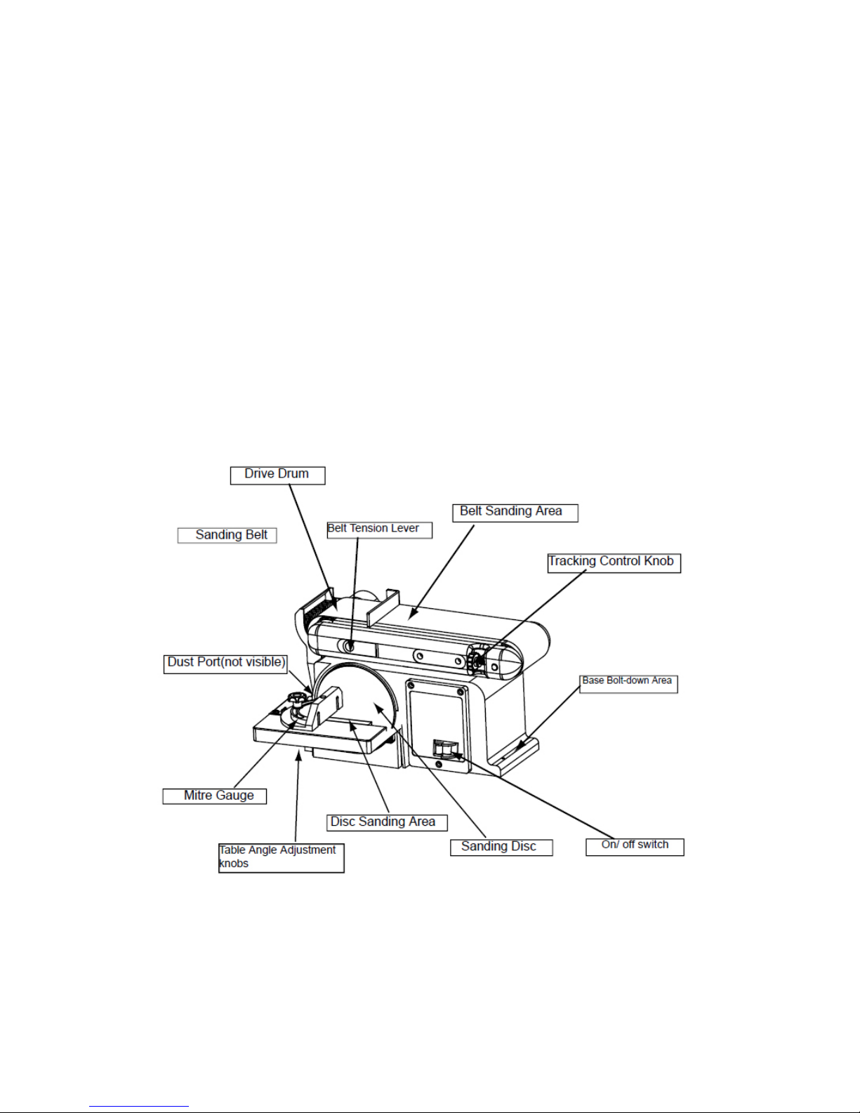
Know Your Belt & Disc Sander
Insert line drawing and show: (minimally)
• On/off switch
• Sanding disc
• Belt sanding area
• Disc Sanding Area
• Table angle adjustment knobs
• Dust port
• Mitre gauge
• Base – bolt-down area
• Tracking control knob
4
Page 5
Operating Instructions
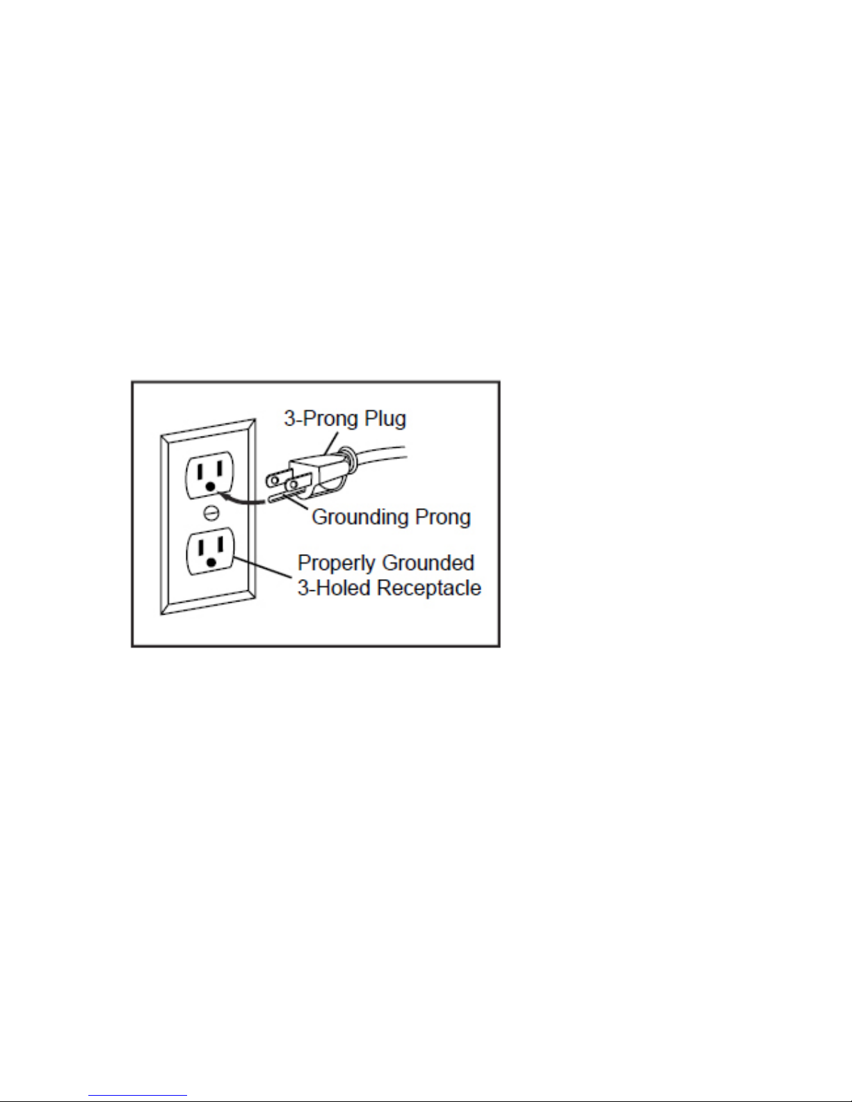
Before You Start – Electrical
In the event of a malfunction or short circuit, grounding provides the path of least resistance for
electrical current and reduces the risk of electric shock for the operator. This tool is equipped with an
electric cord that has an equipment grounding conductor and a grounding plug. The plug MUST be
plugged into a matching outlet that is properly installed and grounded in accordance with ALL local
codes and ordinances.
DO NOT MODIFY THE PLUG PROVIDED. If it will not t the outlet, have the proper outlet installed by
an electrician.
Figure 2
IMPROPER CONNECTION of the equipment grounding conductor can result in increased risk of
electric shock. The conductor with the green insulation (with or without yellow stripes) is the equipment
grounding conductor. If repair or replacement of the electric cord or plug is necessary, DO NOT
connect the equipment grounding conductor to a live terminal.
CHECK with a qualied electrician or service personnel if you do not completely understand the
grounding instructions, or if you are not sure if the tool is properly grounded.
This tool is intended for use on a circuit that has an outlet that looks like the one illustrated. The
original tool has a grounding plug that looks like the plug illustrated (Figure 2).
5
Page 6

Use of Extension Cords
USE ONLY THREE-WIRED EXTENSION CORDS that have 3-prong plugs and 3-holed outlets that
accept the tool’s plug. Repair or replace damaged or worn cords immediately.
Be sure your extension cord is properly wired and in good condition. Do not use damaged extension
cords. Always replace a damaged extension cord.
When using an extension cord, be sure to use one heavy enough to carry the current your product will
draw. An undersized cord will cause a drop in line voltage, resulting in loss of power and overheating.
The table below shows the correct size to use according to the cord length and the amperage draw
of the tool (specied on the nameplate). When in doubt, use the next heavier gauge. The smaller the
gauge number, the heavier the cord. (AWG = American Wire Gauge).
Minimum Gauge for Extension Cords (AWG)
(when using 120 volts only)
Ampere Rating Total Length of Cord in Feet (meters)
More Than Not more Than 25’ (7.6m) 50’ (15m) 100’ (30.4m) 150’
(45.7m)
0 6 18 16 16 14
6 10 18 16 14 12
10 12 16 16 14 12
12 16 14 12 Not Recommended
Use a separate electrical circuit for your tools. This circuit should not be less than a #12 gauge wire,
and should be protected with a 15 A time-lag fuse or breaker. Before connecting the motor to the
power line, ensure the switch is in the OFF position and the electric current is rated the same as the
current stamped on the motor’s nameplate. Running at a lower voltage will damage the motor and this
damage is not covered by warranty.
6
Page 7
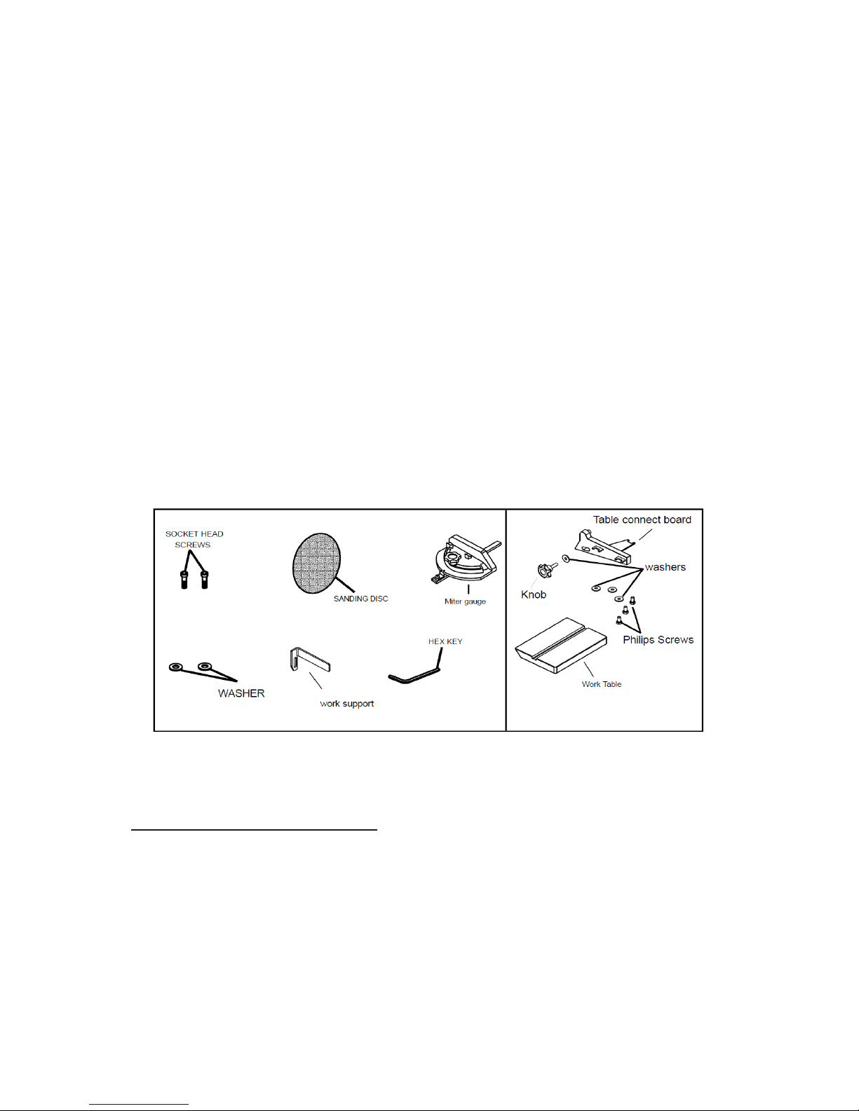
Before You Start - Unpacking
Your Mastercraft belt & disc sander has been shipped completely assembled with the exception of: the
sanding disc, disc guard, mitre gauge, work support and worktable.
Carefully remove all parts from the shipping carton. Do not discard the packing material until you have
carefully inspected the belt & disc sander, identied and located all parts, and satisfactorily operated
your new tool. If all parts are present, proceed to assembly.
Examine all parts to ensure no breakage has occurred during shipping. Missing or damaged parts
should be replaced before use. Should you discover or suspect that parts are missing or damaged, do
not return to the store. Call (Toll-Free) the number on the front of this Owner’s Manual.
Parts & Accessories List
1. Socket head screws
2. Sanding disc
3. Mitre gauge
4. Washers
5. Work support
6. Hex key 15/64” (6 mm?)
7. Worktable
8. Adjustment knob
9. Table connection bracket
10. Phillips screws
Before You Start – Assembly and Installation
WARNING! Always ensure the sander is unplugged prior to attempting any assembly,
installation or changing of parts and accessories.
Mounting the Sander to the Workbench
CAUTION: If during operation there is any tendency for the sander to tip over, slide or walk on
the supporting surface, the sander should be properly mounted to a workbench or stand.
1. Position the sander on the workbench where you expect/intend to use it.
2. Mark the workbench through the mounting holes located in the sander base. Drill holes in the
workbench at the marks.
3. Using long bolts, washers, locking washers and nuts, as shown (not supplied), secure the
sander to the workbench. Note: All bolts should be inserted from the top. Washers and hex
nuts should be fastened from the underside of the workbench.
7
Page 8

Installation of Sanding Disc and Guard
1. Peel backing away from sanding disc.
2. Align perimeter of disc with plate, and press disc firmly into position on plate, leaving no loose
edges.
3. Position disc guard against lower 1/3 of disc, aligning holes as shown.
4. Use a screwdriver to fasten the provided screws and washers securely.
8
Page 9

Installation of Disc-Sander Table Assembly
1. Locate table support and (3) hex head screws, washers and locking washers in loose parts
bag.
2. Place table top-down on a at surface.
3. Position table support against table bottom, aligning holes on support with pre-drilled holes in
table.
4. Fasten table support to table using the hex head screws, washers and locking washers, as
shown.
Mounting of Table Assembly
1. Locate table-lock knob and washer in parts bag.
2. Position table-support bracket so that “index pin” ts into corresponding hole on sander frame
and semi-circular hole aligns with threaded hole in frame.
3. Place washer on threaded shaft of table-lock knob, insert through semi-circular slot, and
tighten into threaded hole.
4. Adjust table to level or to angle desired for sanding.
9
Page 10

Installation of Belt-Sander work support
1. Locate work support and hex screw, washer and locking washer.
2. Hold work support in position and fasten as shown. Do not overtighten.
10
Page 11

Installing or Changing Accessories – Sanding Belts
WARNING! Turn the power off and remove the plug from the outlet before changing the
accessories.
Removal:
1. Slide tension lever to the right to release the belt tension.
2. Slide the used sanding belt off of the rotational mechanism.
Installation:
1. Slide new belt over the belt rotational mechanism – sanding drums. Ensure the belt is centred
on both drums (ends of mechanism).
2. Slide the tension lever to the left to apply tension to the belt.
3. Before using, check belt tracking as described in “Belt Tracking” section, and adjust as
necessary.
Belt Tracking
The belt-tracking adjustment is set at the factory so that the abrasive belt will run true on the drums.
If, however, the belt should track to one side or the other, an adjustment can be made by turning the
tracking knob, which is located on the front right-hand side of the machine. Turning the knob clockwise
will cause the belt to track to the right (towards the disc sander mechanism). Turning the knob counterclockwise will cause the belt to track to the left side of the machine.
11
Page 12

To properly track the sanding belt:
1. Plug in the sander.
2. Turn power switch ON, then immediately OFF, noting whether the belt tends to slide off its
track, and to which side (front or back) of the sander.
3. If the sanding disc did not tend to either side, it is tracking properly.
4. If the sanding belt moves toward the disc (the front side of the sander), turn the tracking knob
clockwise ¼ turn.
5. If the sanding belt moves away from the disc (towards the back side of the sander), turn the
tracking knob counter clockwise ¼ turn.
6. Turn power switch ON, then immediately OFF again, again taking note of any belt movement.
7. Readjust tracking knob another ¼ turn, as necessary.
Installing or Changing Accessories – Sanding Discs
WARNING! Turn the power off and remove the plug from the outlet before changing the
accessories.
Note: Hook & Loop sanding discs cannot be used with this type of sander!
Removal:
1. Remove and set aside mitre gauge.
2. Completely remove the disc-sanding table.
Sanding discs are adhered to the plate using a “pressure-sensitive adhesive”. Remove
sanding disc from disc plate.
12
Page 13

Installation
1. Ensure disc-plate is clean.
2. Peel backing from new sanding disc.
3. Press new sanding disc rmly onto disc-plate.
Note: Hook & Loop sanding discs cannot be used with this type of sander!
Replace the sanding table and handles that were removed in step 2 (above).
Dust Chute/Port – Operation
Sanding operations are inherently dusty. To help minimize the amount of dust that escapes into the
surrounding air, this Mastercraft sander is equipped with a 2 1/4” (57 mm) dust chute (aka: port) that
can be easily connected to a dust-collection system. It is strongly recommended that users employ a
dust-collection system when using this belt & disc sander.
Use of a mask or respirator is still recommended even when a dust-collection system is in use.
13
Page 14

Operating Instructions
Safety - Locking ON/OFF Switch
The rocker ON/OFF power switch is located on the front of the sander, and incorporates a removable
safety switch.
1. Press the side marked ON to turn the sander on.
2. Press the side marked OFF to turn the sander off.
In situations where the sander may be left unattended, the operator has the option of removing the
“yellow” safety portion of the ON/OFF switch to render the sander inoperable. When the operator is
ready to use the machine again, the “yellow” safety portion of the switch may be reinstalled simply by
inserting it into the opening in the switch and pushing it in until it “seats”.
Operating Instructions – Belt Sander – Horizontal and Vertical Sanding
Your Mastercraft belt & disc sander – belt station can sand vertically as well as horizontally. Depending
on operator needs and the workpiece, the work-support can be used with either the horizontal or
vertical position.
To change from one position to the other:
1. Locate the 15/64” (6 mm) hex wrench
2. Loosen the bed-locking hex-socket screw by turning it counter-clockwise.
3. Manually move the work support station into the vertical or horizontal position, as required.
4. Retighten the bed-locking hex-socket screw by turning it clockwise (using the 15/64” (6 mm)
hex wrench).
Operational Note: Sand long workpieces with the sanding belt in the vertical position by moving the
work evenly across the sanding belt.
14
Page 15

Surface Sanding on the Sanding Belt
When sanding at, broad surfaces on the belt sander, hold the workpiece rmly but lightly onto the
surface of the belt and against the work support (work rest), keeping ngers away from the sanding
belt. Consider using a push or hold-down stick.
Note: Use extra caution when sanding very thin pieces, and when sanding extra long pieces, remove
the work support.
Apply only enough pressure to allow the sanding belt to remove material.
Sanding Curved Pieces
When sanding inside-curves on the belt-sander, always sand on the idler drum end of the worksupport station (right side of the machine as shown in diagram).
Hold the workpiece rmly, keeping ngers away from the sanding belt. Keep the curve pressed rmly
against the idler drum, moving the work evenly back and forth across the drum.
Note: Use extra caution when sanding very thin pieces, and apply only enough pressure to allow the
sanding belt to remove the material.
15
Page 16

Sanding Disc Station - Sanding Outside Curves
Always sand outside curves using the sanding disc and moving the workpiece from the left side of
centre, as shown. Keep the curve pressed rmly against the sanding disc, moving the work evenly
from the left side of the sanding disc. Be sure to hold the workpiece rmly onto the surface of the
sanding-disc table.
Mitre Gauge – Disc Sander
A mitre-gauge is supplied with your sander, and can be used on the disc table, as shown. The mitre
gauge head can be set anywhere up to 60º (right or left) by loosening the lock-knob, setting the mitre
gauge head to the desired angle, and retightening the lock-knob.
Sanding Small End Grain and other small surfaces using the Mitre Gauge
Use of the mitre gauge is recommended for sanding small end surfaces on the sanding disc. Note:
Always move the workpiece across the sanding disc from the left side towards the right side, and be
sure to hold the workpiece down tightly onto the table surface.
16
Page 17

Maintenance
WARNING! Turn the power switch “OFF” and disconnect the plug from the outlet prior
to adjusting or maintaining the sander. DO NOT attempt to repair or maintain the electrical
components of the motor. Take the sander to a qualied service technician for this type of
maintenance.
Maintenance Required Frequency
1. Check power cord Before each use.
2. Check sanding belts and discs for damage Before each use.
3. Check moving parts for alignment and binding issues Before each use.
4. Dress sanding surfaces As needed
5. Replace sanding belts or discs (see manual section for specics) As needed.
6. Clean and vacuum dust from the motor housing and other sander parts As needed.
7. Ball Bearings in this tool are lubricated and sealed. They require no further lubrication.
Service beyond recommended maintenance on these tools should only be performed by
an authorized, qualied technician.
17
Page 18

Troubleshooting
Service on these tools should only be performed by an authorized, qualified technician.
SYMPTOM
PROBABLE CAUSE CORRECTIVE ACTION
Sanding Grains easily
rub off belt or discs.
1. Sanding belt/disc has
been stored in an incorrect
environment.
2. Sanding belt/disc has been
damaged or folded.
1. Ensure sanding
accessories are stored
away from extremely hot
or dry temperatures.
2. Store sanding accessories
flat – not bent or folded.
Deep sanding grooves
or scars in workpiece.
1. Sanding belt/disc grit is
too coarse for the desired
finish.
2. Workpiece sanded across
the grain.
3. Too much sanding force on
the workpiece.
4. Workpiece held still against
the belt-disc for too long.
1. Use a finer-grit sanding
accessory.
2. Sand with the grain of the
wood.
3. Reduce pressure on
workpiece while sanding.
4. Keep workpiece moving
while sanding on the
sanding accessory.
Sanding surface clogs
quickly.
1. Too much pressure against
belt/disc.
2. Sanding softwood.
1. Reduce pressure on
workpiece while sanding.
2. Use different stock,
different sanding
accessories, or accept that
this will happen and plan
on cleaning or replacing
belts/discs frequently.
Burns on workpiece. 1. Using a sanding grit that is
too fine.
2. Using too much pressure.
3. Work held still for too long.
1. Use a coarser-grit sanding
accessory.
2. Reduce pressure on
workpiece while sanding.
3. Do not keep workpiece in
one place for too long.
Motor will not start. 4. Low voltage.
5. Open circuit in motor or
loose connections.
6. Blown fuse or breaker.
4. Check power source for
proper voltage.
5. Inspect all lead
connections on motor for
loose or open connections.
(Send for Servicing)
6. Short circuit. (Send for
Servicing.)
7. Improper match between
tool and circuit, fuse or
breaker.
Motor will not start –
fuses or circuit breakers
tripping or blowing.
1. Short circuit in line, cord or
plug.
2. Short circuit in motor or
loose connections.
3. Incorrect fuses or circuit
breakers in power line.
1. Inspect cord or plug for
damaged insulation and
shorted wires.
2. Inspect all connections on
motor for loose or shorted
terminals and/or worn
insulation.
3. Install correct fuses or
circuit breakers or switch
tool to an appropriately
sized circuit.
18
Page 19

Motor overheats. 1. Motor overloaded.
2. Extension cord too
long and of insufficient
gauge (weight).
1. Reduce load on motor
(pressure on object being
sanded).
2. Utilize an extension cord of
appropriate gauge and length
or plug tool directly into outlet.
Motor stalls (resulting in
blown fuses or tripped
circuit).
1. Short circuit in motor
or loose connections.
2. Low voltage.
3. Incorrect fuses or
circuit breakers in
power line.
4. Motor overload.
1. Inspect connections on motor
for loose or shorted terminals
or worn insulations. (Send for
Servicing.)
2. Correct low voltage conditions
(for example: improper
extension cord length and/or
gauge).
3. Install CORRECT fuses or
circuit breakers or plug tool
into an appropriate circuit,
matched to an appropriate
fuse or breaker.
4. Reduce the load on the motor.
Machine slows when
operating.
1. Feed rate too
great.
2. Undersized
circuit or use
of undersized
extension cord.
1. Reduce the rate at which
the workpiece is fed into the
working area of the tool.
2. Ensure circuit wires or
extension cords are proper
gauge, or eliminate use of
extension cords.
Machine vibrates
excessively.
1. Incorrect motor
mounting.
2. Incorrect sanding-belt
tension.
3. Weak or broken
tension spring.
4. Idler roller is too loose.
5. Broken/defective
sanding accessories.
1. Have motor mountings
inspected by service
technician.
2. Adjust tension adjustment
knob. Follow belt-tensioning/
tracking instructions in this
manual.
3. Have tension spring replaced
by service technician.
4. Have service technician
adjust idler roller.
5. Replace sanding belt/disc.
Workpiece frequently
gets pulled out of
operator’s hands.
1. Not supporting the
workpiece against the
stop.
2. Attempting to sand
(unaided) a workpiece
that is too small.
1. Use the platen (backstop) or
mitre gauge to support the
workpiece.
2. Use another hand tool or jig to
grasp or hold the workpiece.
Workpiece lifts up from
the sanding disc/table.
1. Sanding on the “up”
side of the wheel.
1. Sand on right side of sanding
disc (as operator faces the
disc).
19
Page 20

Parts Schematic
20
Page 21

Parts List
21
Item
Number
Descriptions QTY
Item
Number
Descriptions QTY
1
Phillips Screw M4X6
4
45
Idler Drum
1
2
Flat Washer D4
4
46
Idler Shaft
1
3 Base Cover
1
47
Phillips Screw M5X20
2
4
Phillips Screw ST4.2X10
2
49
Screw Bushing
1
5
Toothed Lock Washer D4
2
50
Draw Extend Spring
Ⅰ
1
6
Disc Cover
1
51
Belt Tension Knob
1
7
Disc Paper 80#
1
52
Big Flat Washer D5
1
8
Hex Socket Round Head Screw M6X16
1
53
Hex Nut,Type I M6
3
9
Toothed Lock Washer D6
2
54
Phillips Screw M5X16
1
10
Disc
1
55
Adjust Knob
1
11
Wheel Box
1
56
Flat Washer D6
4
12
Phillips Screw M5X8
4
57 Rubber Washer
1
13
Spring Washer D5
1
58
Adjust Spring 1
14
Flat Washer D5
1
59 Belt Support
1
15
Toothed Lock Washer D5
2
60
Work Rest
1
17
Base
1
61
Driving Pulley
1
18
Phillips Screw ST4.2X20
3
62
Hex Flat Lock Washer M8X12
2
19
Wire Connection Box Cover
1
63
Driving Pulley
1
20
Phillips Screw ST2.9X28
1
64
Bearing Cap
1
21
Relay
1
65
Support Cover 1
22
Wire Connection Box
1
66
Phillips Screw
M5X10
1
23
Phillips Screw M5X10
7
67
Cog Belt Guard Cover
1
24
Electromagnetism Power Switch
1
68
Phillips Screw M5X16l
2
25
Phillips Screw M6X8
1
69 Special Locked Washer
2
26
Spring Washer D6
4
70
Cog Belt
1
27
Hex Nut,Type I M5
1
71
Driven Pulley
1
28
Capacitor
1
72
Phillips Screw M5X25
1
29
Capacitor Support
1
73
Bearing Base
1
30
Phillips Screw M5X12
1
74
Phillips Screw M6X25
1
31
Hex Bolt M6X12
3
75
Hex Socket Round Head Screw M8X25
1
32
Big Flat Washer D6
5
76
Cog Belt Guard Cover
1
33
Work Table Support Angle Plate
1
77
Square Nut
1
34
Miter Gauge Knob
2
78
Driving Pulley
1
35
Work Table
1
79
Phillips Screw M4X6
4
36
Miter Gauge Bar
1
81 Motor Assy
1
37
Point of Miter Gauge
1
82
Cord & Plug
1
38
Miter Gauge of Work Table
1
83
Dust Collect
1
39
Pulley Guard Plate
2
85
Support cushion
1
40
Tension Sping 1
86
Belt frame support
1
41
Bushing
2
87
Belt 100#
1
42
Belt Tension Support
1
88
Switch protect cover
1
43
Spring Retaining Ring for Shaft D12
4
89
Phillips Screw
2
44
Bearing101Z
4
90
Flat Washer D8
2
91
Hex Socket Round Head Screw M8X16
2
Page 22

Mastercraft Warranty
This Mastercraft® product is guaranteed for 3 years from the date of original retail
purchase (Proof of purchase required) against defects in materials or workmanship
subject to the following exclusions:
a) Any part that has become inoperative due to abuse, misuse, lack of proper
maintenance as outlined in the Owners Manual, professional or commercial use or
accidental damage.
b) Normal wear and tear parts, such as (but not limited to) spark plugs, air lters,
starter cords, carbon brushes, etc.
c) Routine maintenance and consumable items, such as fuel, lubricants, vacuum
bags, blades, belts, sandpaper, bits, uids, etc., tune-ups or adjustments.
d) Where damage is caused by repairs made or attempted by others (persons not
authorized by the manufacturer [or retailer]).
Exclusively at our option, we will repair or replace warrantable products at no charge
to the original owner. This warranty gives you specic legal rights, and you may have
other rights that vary in certain provinces.
Additional Limitations
Neither the retailer nor the manufacturer shall be liable for any other expense, loss or
damage, whether direct, incidental, consequential or exemplary, arising in connection
with the sale or use or inability to use this product.
This guarantee applies only to the original owner, and may not be transferred.
Notice to Consumer
The provisions contained in this written guarantee are not intended to limit, modify,
take away from, disclaim or exclude any warranties set forth in, or the operation of,
any applicable provincial or federal legislation.
22
 Loading...