

Page 1
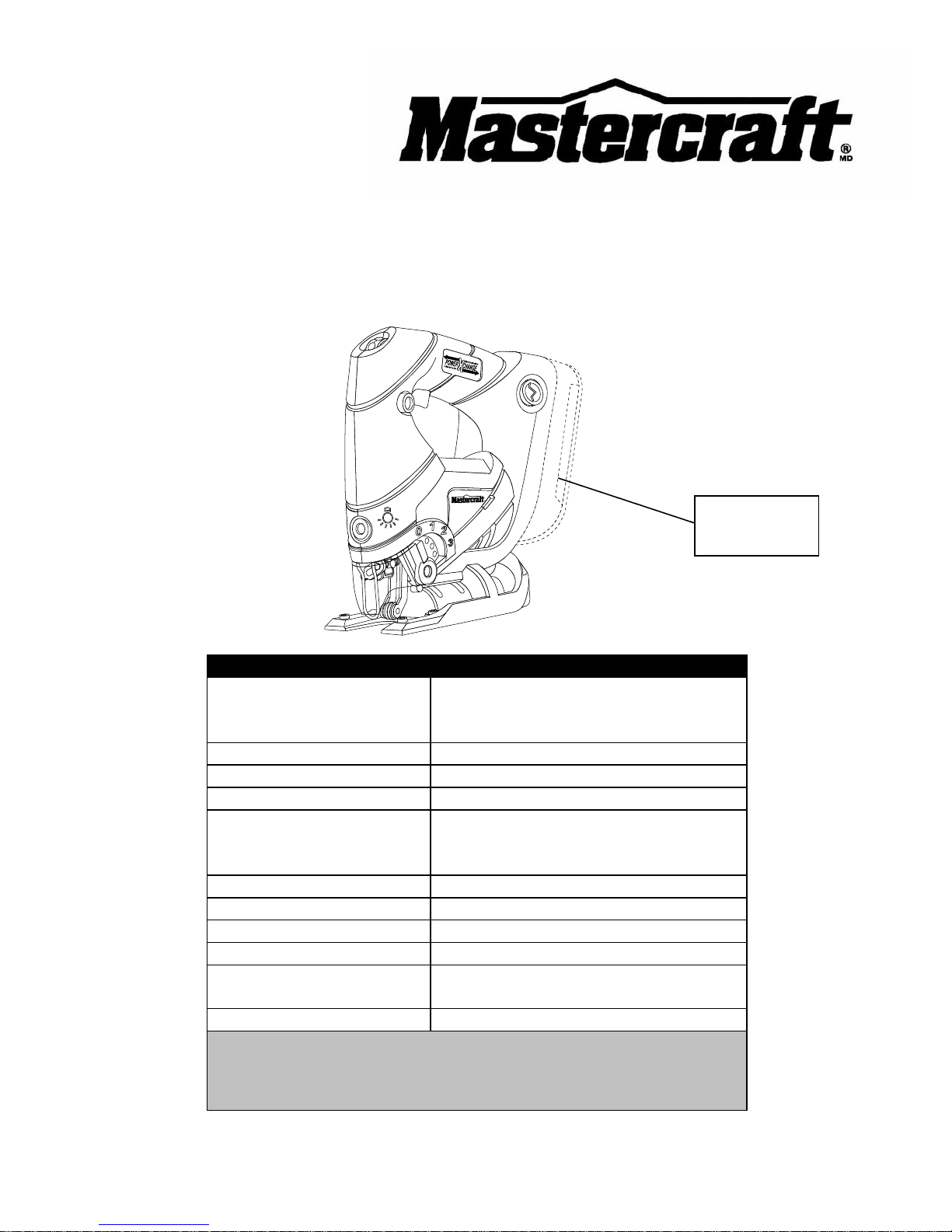
18 V CORDLESS ORBITAL JIGSAW
(Battery & Charger Not Included)
54-8110-2
Owner’s Manual
PRODUCT SPECIFICATIONS
Battery:
18 V
Ni-Cd (54-3102-2; sold separately)
Li-ion (54-3100-6; sold separately)
Variable speed:
800–2800 SPM (no load)
Blade change system:
Tool free
Stroke length:
11/16" (18 mm)
Cutting capacity @ 90°:
Wood: 2 1/2" (63.5 mm)
Aluminum: 3/8" (9.5 mm)
Steel: 5/32" (4 mm)
Blade types:
U- and T- shank
Base plate tilt:
45°
Pendulum positions:
4 (including neutral)
Worklights:
Single LED
Chargers:
1-hour, diagnostic (54-3103-0 or
54-3101-4; both sold separately)
Weight:
3 lb 15 oz (1.8 kg) without battery
NEED ASSISTANCE?
Call us on our toll-free Customer Support Line:
1-800-689-9928
Imported by Mastercraft Canada Toronto, Canada M4S 2B8
Battery not
included
Page 2

2
Product specifications ………….…………………………………………………….
1
Table of contents ……………………………………………………………………...
2
General safety warnings ……………………………………………………………..
3–4
Eye, ear & lung protection ……………………………………………………………
3–4
Electrical safety ……………………………………………………………………….
4
Power tool safety ……………………………………………………………………...
5–7
General safety rules …………………………………………………………………..
5
Work area ………………………………………………………………….…………..
5
Electrical safety ……………………………………………………………………….
5
Personal safety ………………………………………………………………………..
5–6
Use and care of power tools .………………………………………………………..
6
Service …………………………………………………………………………………
6–7
Specific safety rules …………………………………………………………………..
7–8
Battery and charger safety …………………………………………………………..
8
Symbols ………………………………………………………………………………..
9
Know your cordless jigsaw …………………………………………………………..
10
Accessories and contents ……………………………………………………………
11–12
Available accessories ………………………………………………………………...
11
Contents ……………………………………………………………………………….
11–12
Assembly and operation ……………………………………………………………..
13–21
Installing a battery in the jigsaw ……………………………………………………..
13
Installing a blade ………………………………………………………………………
13–14
Removing a blade …………………………………………………………………….
14
Hex key storage ……………………………………………………………………….
14
Setting the bevel cutting angle ………………………………………………………
14–15
Setting the orbital cutting angle ……………………………………………………..
15
LED worklight ………………………………………………………………………….
16
Blade storage ………………………………………………………………………….
16
Variable speed control ………………………………………………………..
16
Lock-off button ………………………………………………………………………...
16
Trigger switch ………………………………………………………………………….
16–17
Materials you can cut …………………………………………………………………
17
General cutting ………………………………………………………………………..
18–19
Bevel cutting …………………………………………………………………………..
19–20
Plunge cutting …………………………………………………………………………
20–21
Metal cutting …………………………………………………………………………...
21
Maintenance …………………………………………………………………………..
22
Exploded view …………………………………………………………………………
23
Parts list ………………………………………………………………………………..
24–25
Warranty ……………………………………………………………………….………
26–27
TABLE OF CONTENTS
Page 3
3
EYE, EAR & LUNG PROTECTION
This instruction manual includes the following:
General Safety Rules
Specific Safety Rules and Symbols
Functional Description
Assembly
Operation
Maintenance
Accessories
!
ALWAYS WEAR EYE PROTECTION THAT CONFORMS WITH CSA
REQUIREMENTS or ANSI SAFETY STANDARD Z87.1
FLYING DEBRIS can cause permanent eye damage. Prescription
eyeglasses ARE NOT a replacement for proper eye protection.
WARNING: Non-compliant eyewear can cause serious injury if
broken during the operation of a power tool.
SAVE THESE INSTRUCTIONS FOR REFERENCE
WARNING: Use hearing protection, particularly during extended
periods of operation of the tool, or if the operation is noisy.
!
GENERAL SAFETY WARNINGS
CAUTION: Before using this tool or any of its accessories, read this
manual and follow all Safety Rules and Operating Instructions.
!
Page 4
4
ELECTRICAL SAFETY
WARNING: To avoid electrical hazards, fire hazards or damage to the
tool, use proper circuit protection.
This tool is wired at the factory for 110–120 V operation. It must be
connected to a 110–120 V, 15 A circuit that is protected by a time-delayed
fuse or circuit breaker. To avoid shock or fire, replace power cord
immediately if it is worn, cut or damaged in any way.
GENERAL SAFETY WARNINGS
WEAR A DUST MASK THAT IS DESIGNED TO BE USED WHEN
OPERATING A POWER TOOL IN A DUSTY ENVIRONMENT.
WARNING: Dust that is created by power sanding, sawing, grinding,
drilling, and other construction activities may contain chemicals that are
known to cause cancer, birth defects, or other genetic abnormalities. These
chemicals include:
Lead from lead-based paints
Crystalline silica from bricks, cement, and other masonry products
Arsenic and chromium from chemically treated lumber
The level of risk from exposure to these chemicals varies, according to how
often this type of work is performed. In order to reduce exposure to these
chemicals, work in a well-ventilated area, and use approved safety
equipment, such as a dust mask that is specifically designed to filter out
microscopic particles.
!
Page 5

5
GENERAL SAFETY RULES
WARNING: Read and understand
all instructions. Failure to follow all
instructions listed below may result in
electric shock, fire and/or serious personal
injury.
WORK AREA
Keep your work area clean and well lit.
Cluttered benches and dark areas invite
accidents.
Do not operate power tools in potentially
explosive environments, such as in the
presence of flammable liquids, gas or dust.
Power tools create sparks that may ignite
dust or fumes.
Keep bystanders, children and visitors
away while operating the tool. Distractions
can cause the operator to lose control.
ELECTRICAL SAFETY
Double insulated tools are equipped with a
polarized plug (one blade is wider than the
other). This plug will only fit into a
polarized plug one way.
If the plug does not fit into the outlet
properly, reverse the plug. If it still does not
fit, contact a qualified electrician to install a
polarized outlet. Do not alter the plug in
any way. Double insulation eliminates the
need for the three-pronged grounded
power cord and grounded power supply
system.
Avoid contact between the operator's body
and grounded surfaces such as pipes,
radiators, ranges, and refrigerators. There
is an increased risk of electric shock if the
operator's body is grounded.
Do not expose power tools to rain or wet
conditions. Water entering the power tool
will increase the risk of electric shock.
Do not abuse the cord. Do not use the
power cord to carry the tool or to pull the
plug out of the outlet. Keep the power cord
away from heat, oil, sharp edges, and
moving parts. Replace a damaged power
cord immediately. A damaged power cord
increases the risk of electric shock.
When operating a power tool outdoors,
use an outdoor-rated extension cord type
“W-A” or “W”. These cords are rated for
outdoor use and they reduce the risk of
electric shock.
PERSONAL SAFETY
Stay alert, be aware of the surroundings,
and use common sense when operating a
power tool. Do not use a power tool while
tired or under the influence of drugs,
alcohol, or medication. A moment of
inattention while operating a power tool
may result in serious personal injury.
Dress properly. Do not wear loose clothing
or jewellery.
Contain long hair. Keep hair, clothing, and
gloves away from moving parts. Loose
clothing, jewellery, or long hair can get
caught in moving parts.
!
POWER TOOL SAFETY
Page 6

6
PERSONAL SAFETY – cont’d
Avoid accidental start-ups. Verify that the
switch is in the OFF position before
plugging in the tool. Carrying a power tool
with a finger on the switch or plugging in a
tool that has the switch in the ON position
invites accidents.
Remove adjusting keys and wrenches
before turning the tool ON. A wrench or
key that is left attached to a rotating part of
the tool may result in personal injury.
Do not overreach. Keep proper footing and
balance at all times. Proper footing and
balance allows the operator to maintain
better control of the tool in unexpected
situations.
Use safety equipment. Always wear eye
protection.
Use a dust mask, non-skid safety shoes, a
hardhat, or hearing protection when
appropriate.
USE AND CARE OF POWER TOOLS
Use clamps or another practical means to
secure and support the workpiece to a
stable platform. Holding the work in a hand
or against the body is not stable, and may
lead to loss of control.
Do not force the tool. Use the correct tool
for the application. The correct tool will do
the job better and safer when used at the
rate that it was designed to work at.
Do not use a power tool if it cannot be
turned ON or OFF using the power switch.
A tool that cannot be controlled using the
switch is dangerous, and must be repaired.
Disconnect the plug from the outlet before
making any adjustments, changing
accessories, or storing the tool. Such
preventive safety measures reduce the risk
of accidental start-ups.
When power tools are not in use, store
them out of the reach of children or
untrained persons. Tools are dangerous in
the hands of untrained users.
Maintain tools with care. Keep cutting tools
sharp and clean. Properly maintained
cutting tools with sharp cutting edges are
less likely to bind, and are easier to
control.
Inspect the tool for misalignment or binding
of moving parts, broken parts, and any
other condition that may affect the
operation of the tool. If it is damaged, have
the tool serviced before using it. Many
accidents are caused by poorly maintained
tools.
Use only accessories that are
recommended by the manufacturer for this
model. Accessories that are suitable for
one tool may become hazardous when
used with another tool.
SERVICE
Tool servicing must be performed by
qualified personnel. Service or
maintenance performed by non-qualified
personnel could result in a risk of injury.
POWER TOOL SAFETY
Page 7

7
SERVICE – cont’d
When servicing a tool, use only identical
replacement parts. Follow the instructions
in the Maintenance section of this Manual.
The use of unauthorized parts or failure to
follow the instructions in the Maintenance
section of this Manual may create a risk of
electric shock or injury.
WARNING: Know your cordless
jigsaw. Do not plug in the charger or
install the battery in the tool until you
have read and understand this
Instruction Manual. Learn the tool’s
applications and limitations, as well as
the specific potential hazards related to
this tool. Following this rule will reduce the
risk of electric shock, fire, or serious injury.
Always wear eye protection. Any power
tool can throw foreign objects
into your eyes and cause
permanent eye damage.
ALWAYS wear safety goggles
(not glasses) that comply with ANSI safety
standard Z87.1. Everyday glasses have
only impact resistant lenses. They ARE
NOT safety glasses.
WARNING: Glasses or goggles
not in compliance with ANSI Z87.1
could cause serious injury when they
break.
Always wear safety goggles, hearing
protection and a dust mask. Use only in
well-ventilated areas. Using personal
safety devices and working in a safe
environment reduces the risk of injury.
Hold the tool by insulated gripping
surfaces when performing an operation
where the saw blade may contact hidden
wiring or its own cord. Contact with a “live”
wire will make exposed metal parts of the
tool “live” and shock the operator.
Always make sure the work surface is free
of nails and other foreign objects. Cutting
into a nail can cause the blade and the tool
to jump and damage the blade.
Never hold the workpiece in one hand and
the tool in the other hand when sawing.
Never place your hands near or below the
cutting surface. Clamping the material and
guiding the tool with both hands is much
safer.
Never lay the workpiece on hard surfaces
like concrete, stone, etc. The protruding
blade may cause the tool to jump.
DANGER: Always remove the
battery when changing the blade and when
making adjustments.
Use only U- or T- shank blades that are
designed specifically for jigsaw use. Never
use a broken blade, as it will not be
securely held in the tool.
SPECIFIC SAFETY
RULES
! ! !
POWER TOOL SAFETY
Page 8

8
After changing a blade, make sure the
blade is securely held in the blade holder.
Loose blades will be violently thrown.
Never touch the blade during or
immediately after use. After use, the blade
is too hot to be touched by bare hands.
Never use dull or damaged blades. Sharp
blades must be handled with care.
Damaged blades can snap during use.
Dull blades require more force to cut the
workpiece, possibly causing the blade to
break.
Always use the straight reciprocating
action when cutting metal. Blades will last
longer and will be less likely to break.
Battery packs and chargers must be
purchased separately.
This jigsaw has been designed to be
powered by one of the following battery
packs:
● 18 V Nickel-Cadmium #54-3102-2
● 18 V Lithium-ion #54-3100-6
WARNING: Only use the battery
packs listed above to power this tool.
Using any other battery pack could
cause serious injury or damage the
tool.
Both battery packs can be charged using
one of the following chargers:
● 14.4 V / 18 V LED Diagnostic Battery
Charger #54-3103-0
● 14.4 V / 18 V LCD Diagnostic Battery
Charger with LCD Status Display
#54-3101-4
WARNING: Only use the battery
chargers listed above. Charging any
other batteries may damage the charger
and possibly cause serious injury.
WARNING: Follow all safety rules
and warnings included with the battery
pack and charger purchased for use
with this tool. Failure to follow those
safety rules and warnings may result in
serious injury or damage to the charger
and battery pack.
Never dispose of defective batteries with
your household waste. Always recycle
defective batteries in accordance with your
local municipal policies.
BATTERY AND
CHARGER SAFETY
!
!
SPECIFIC SAFETY RULES
!
Page 9
9
V
Volts
A
Amperes
Hz
Hertz
W
Watts
kW
Kilowatts
Microfarads
L
Litres
kg
Kilograms
H
Hours
N/cm2
Newtons per square
centimetre
Pa
Pascals
Min
Minutes
S
Seconds
Alternating current
Three-phase alternating
current
Three-phase alternating
current with neutral
Direct current
No load speed
Alternating or direct
current
Class II construction
Splash-proof
construction
Watertight construction
Protective grounding at
grounding terminal,
Class I tools
Revolutions or
reciprocations per
minute
Diameter
Off position
Arrow
Warning symbol
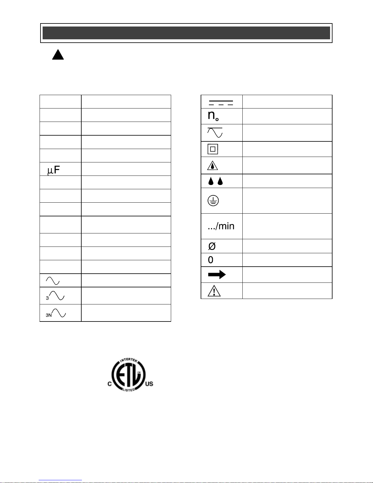
SYMBOLS
WARNING: Some of the following symbols may appear on the cordless
jigsaw. Study these symbols and learn their meaning. Proper interpretation of
these symbols will allow for more efficient and safer operation of this tool.
!
This symbol designates that this tool is
listed with Canadian requirements by ETL
Testing Laboratories, Inc.
Conforms to UL STD. 73
Certified to CAN/CSA STD. C22.2 No. 12
3042597
HOMOLOGUÉ
Page 10

10
KNOW YOUR CORDLESS JIGSAW
Battery release
button
Trigger
switch
Lock-off
button
Blade holder
LED worklight
switch
Blade guide
roller
Chip guard
Tilting sole
plate
Motor vents
Hex key holder
(inside battery
cavity)
Cutting action
lever
Bevel angle
scale
Blade storage
cover
Speed control
wheel
Battery not
included
Page 11

11
AVAILABLE ACCESSORIES
WARNING: Use only saw blades
that are recommended for this cordless
jigsaw. Follow the instructions that
accompany the saw blades. The use of
improper saw blades may result in
injury to the operator or damage to the
jigsaw.
Before using any accessory, carefully read
the instructions or the owner’s manual for
the accessory.
U- or T-shank jigsaw blades
WARNING: If any part is missing or
damaged, do not install a battery in the
tool until the missing or damaged part is
replaced.
CONTENTS
Carefully unpack the cordless jigsaw.
Compare the contents against the
“JIGSAW COMPONENTS” chart below.
NOTE: See illustration of the cordless
jigsaw and components on Page 12.
Battery packs and chargers must be
purchased separately.
● This jigsaw has been designed to be
powered by one of the following
battery packs:
● 18 V Nickel-Cadmium #54-3102-2
● 18 V Lithium-ion #54-3100-6
WARNING: Only use the battery
packs listed above to power this tool.
Using any other battery pack could
cause serious injury or damage the
tool.
Both battery packs can be charged using
one of the following chargers:
● 14.4 V / 18 V LED Diagnostic Battery
Charger #54-3103-0
● 14.4 V / 18 V LCD Diagnostic Battery
Charger with LCD Status Display
#54-3101-4
WARNING: Only use the battery
chargers listed above. Charging any
other batteries may damage the charger
and possibly cause serious injury.
WARNING: Follow all safety rules
and warnings included with the battery
pack and charger purchased for use
with this tool. Failure to follow those
safety rules and warnings may result in
serious injury or damage to the charger
and battery pack.
ACCESSORIES AND CONTENTS
!
!
JIGSAW COMPONENTS
KEY
DESCRIPTION
QTY
A
Jigsaw assembly
1
B
1/8" (3 mm) hex key
1
C
General purpose
blade
1
Owner’s Manual
1
! ! !
!
Page 12

12
CONTENTS
Page 13

13
INSTALLING A BATTERY IN THE
JIGSAW
1. Remove the discharged battery (1)
from the tool by pressing on one the
battery release buttons (2) on the
sides of the handle (Fig. 1).
NOTE: There is one battery release button
on each side of the handle. It is only
necessary to press one of the buttons to
release the battery.
2. Pull the battery out of the tool handle
(3).
3. Slide the fully charged battery into the
matching cavity in the tool handle
where the discharged battery has
been removed.
NOTE: Make sure the battery is fully
engaged with the mounting slots in the tool
handle. The battery release buttons will
“click” into place when the battery is fully
installed.
WARNING: Do not immerse the
battery pack in water. Sudden cooling
could cause the hot battery to explode or
leak.
INSTALLING A BLADE
WARNING: Always remove the
battery before installing or removing a
blade or adjusting the jigsaw in any
way.
1. To install a blade in the jigsaw,
remove the chip guard by carefully
pulling outward on the chip guard
mounting points (1) on each side of
the jigsaw (Fig. 2).
ASSEMBLY AND OPERATING
Fig. 1
!
!
Fig. 2
Page 14

14
INSTALLING A BLADE – cont’d
2. Push upward on the blade locking
lever (2) (Fig. 3).
3. Insert the appropriate blade (3) into
the blade slot (4) as far as it will go.
NOTE: Make sure the rear edge of the
blade is nested in the blade guide roller
(5).
4. Release the blade-locking lever.
NOTE: The blade will automatically be
locked into the blade holder. Pull outward
on the blade to ensure it is properly locked
into the blade holder.
REMOVING A BLADE
To remove a blade, simply push upward
on the blade locking lever and remove the
blade from the blade holder.
HEX KEY STORAGE
The 1/8” (3 mm) hex key (1) for adjusting
the bevel cutting angle is stored in the
lower part of the battery cavity (2) (Fig. 4).
SETTING THE BEVEL CUTTING ANGLE
Bevel cutting angles may be adjusted from
0° to 45° either left or right. To adjust the
bevel angle:
1. Loosen both base pivot screws (1)
until the base (2) can be rotated
(Fig. 5).
NOTE: Use 1/8" (3 mm) hex key supplied.
ASSEMBLY AND OPERATING
Fig. 3
Fig. 5
Fig. 4
Page 15

15
SETTING THE BEVEL CUTTING ANGLE –
cont’d
2. Bevel angles (3) are marked on a
scale located on the rear of the base
(Fig. 6).
3. Align the bevel angle index mark (4)
with the desired bevel angle on the
rear of the base.
NOTE: Use a protractor to check the bevel
angle between the blade and the base.
4. Once desired bevel angle is obtained,
lock the base by tightening base pivot
screws.
5. Make a test cut in a scrap piece of
material and measure the bevel angle.
Adjust bevel angle if necessary.
SETTING THE ORBITAL CUTTING
ANGLE
The variable orbital cutting action allows
you to select one of four different blade
angles.
To set the orbital cutting angle, move the
orbital cutting button forward or backward
to the desired setting number (1) (Fig. 7).
NOTE: The orbital setting button will “click”
at each of the four positions. Slide the
orbital button slightly forward or backward
until it locks into place.
Fig. 6
ASSEMBLY AND OPERATING
Position
Angle
Material
0
Neutral
Metal
1
Small
Hard wood
2
Medium
Medium
hard wood
3
Full
Soft wood
Fig. 7
Page 16

16
LED WORKLIGHT
The LED worklight (1) is located in the
front of the saw housing (Fig. 8).
To turn the worklight ON, press the
worklight switch (2) once. To turn the
worklight OFF, press the worklight switch a
second time.
BLADE STORAGE
To access the blade storage, pull the blade
storage cover (1) back from the sole plate
(Fig. 9).
VARIABLE SPEED CONTROL
Set the jigsaw speed by rotating the
variable speed control wheel (1) to the
appropriate speed (Fig. 10). Position the
speed control dial at “1” for the slowest
speed, “3” for medium speed and at “6” for
the highest speed.
LOCK-OFF BUTTON
The lock-off button (1) is a safety device
designed to reduce the possibility of a user
accidentally starting the jigsaw (Fig. 11).
This button must be pressed before the
trigger switch (2) can be squeezed.
NOTE: The lock-off button can be pressed
from either the left or right side of the
handle.
TRIGGER SWITCH
The trigger switch turns the jigsaw ON and
OFF.
ASSEMBLY AND OPERATING
Fig. 9
Fig. 8
Fig. 10
Page 17

17
TRIGGER SWITCH – cont’d
1. To turn the jigsaw ON, press the lockoff button (1) with your thumb.
2. While holding the lock-off button in the
pressed position, squeeze the trigger
switch (2) to start the jigsaw.
3. Once the jigsaw starts, release the
lock-off button. The jigsaw will remain
running until the trigger switch is
released.
4. To turn the jigsaw OFF, release the
trigger switch.
NOTE: To re-start the jigsaw, the lock-off
button must be pressed again before the
trigger switch is pressed.
MATERIALS YOU CAN CUT
This jigsaw is a versatile tool that allows
you to cut many different types of
materials. Some of these materials
include:
● Wood products such as lumber,
hardwood, plywood, composite board,
and panelling
● Drywall
● Fibre board and plastic
● Metals such as pipe, steel rods, sheet
steel, aluminum, brass, and copper.
NOTE: There are many different types of
blades available. Generally, there are
metal cutting blades (fine teeth) and wood
cutting blades (coarse teeth). Use the
correct blade for your application. The
packaging on the blade will indicate the
type of materials each blade is designed to
cut.
ASSEMBLY AND OPERATING
Fig. 11
Page 18

18
GENERAL CUTTING
1. Clearly mark the workpiece to locate
the position of the cut.
2. Hold smaller workpieces with a vise.
Clamp larger workpieces to a
workbench or table.
DANGER: Any workpiece that is
not adequately clamped in place may
come loose and cause serious injury.
Never hold the workpiece with your
hand.
For safety reasons, the operator
must read the sections of this
Owner’s Manual entitled “GENERAL
SAFETY WARNINGS”, “POWER
TOOL SAFETY”, “SPECIFIC SAFETY
RULES”, “BATTERY AND CHARGER
SAFETY” and “SYMBOLS” before
using this cordless jigsaw.
Verify the following every time the
cordless jigsaw is used:
1. The blade is sharp and in good
condition.
2. The blade is firmly clamped into
the blade holder.
3. The workpiece is properly
secured.
4. Safety glasses and hearing
protection are being worn.
Failure to observe these safety rules
will significantly increase the risk of
injury.
WARNING
!
ASSEMBLY AND OPERATING
!
Page 19

19
GENERAL CUTTING – cont’d
WARNING: Keep hands and
fingers away from between the motor
housing and blade holder. Do not reach
underneath workpiece while jigsaw is
running.
3. Rest the front of the jigsaw base on
the workpiece and align cutting edge
of the blade with the cutting line on
your workpiece (Fig. 12). Make sure
the power cord is out of your way and
not in the path the blade will follow.
4. While firmly gripping the jigsaw, and
with the blade NOT in contact with the
surface to be cut, start the jigsaw by
pressing the lock-off button and
squeezing the trigger switch.
5. Once the jigsaw has reached the
desired speed, gradually bring the
moving blade into contact with the
workpiece at the appropriate location.
NOTE: Apply enough downward pressure
to keep the jigsaw steady and only enough
forward pressure to keep the blade cutting
freely.
CAUTION: Do not force the
jigsaw. Use only enough force to keep
the blade cutting. Excessive pressure
on the blade will cause it to bend and
twist, which may result in breaking the
blade.
BEVEL CUTTING
Bevel cutting angles may be adjusted from
0° to 45° either left or right. To adjust the
bevel angle, refer to Fig. 5.
!
Fig. 12
!
ASSEMBLY AND OPERATING
Page 20

20
BEVEL CUTTING - cont’d
Once the cutting angle has been verified,
proceed with the cutting activity as outlined
in “GENERAL CUTTING” above.
PLUNGE CUTTING
WARNING: To avoid loss of
control, broken blades or damage to the
workpiece, always use extreme caution
when making plunge cuts. It is not
recommended to plunge cut any
material other than wood. Wherever
possible, drill a pilot hole 3/8" (9.5 mm)
or larger in the area to be cut out and
start cutting with the blade in the pilot
hole. This will avoid the need to plunge
cut.
NOTE: Use only blades with 7 teeth per
inch for plunge cutting.
1. To plunge cut an inside hole, clearly
mark the cutting line on the workpiece.
2. Set the bevel angle at 0°, and then
lock the base plate.
3. Tilt the jigsaw forward so it rests on
the front edge of the base plate and in
a position where the blade will NOT
touch the workpiece when the switch
is turned ON (Fig. 13).
NOTE: Make sure the saw blade is inside
the area to be cut.
4. Start the jigsaw and slowly lower the
blade onto the workpiece while
making sure the front of the saw base
remains in contact with the workpiece.
Allow the blade to slowly cut through
the wood.
ASSEMBLY AND OPERATING
!
Fig. 13
Page 21

21
PLUNGE CUTTING – cont’d
5. Continue lowering the blade into the
workpiece until the jigsaw base rests
flat on the workpiece. Continue
sawing toward the cutting line and
complete the cut as required.
METAL CUTTING
Many types of metal can be cut with your
jigsaw. When cutting any kind of material,
be careful not to twist or bend the blades.
Do not force the blade. If the blade
chatters or vibrates excessively, use a
finer toothed blade. If the blade heats
excessively, reduce the speed of cutting. If
the blade teeth become clogged when
cutting soft metals, such as aluminum, use
a coarser blade with fewer teeth per inch.
Use kerosene when cutting soft metals
and oil when cutting steel to keep the
blade cool and to extend the blade life.
Clamp all work firmly and jigsaw as close
as possible to the clamping point to
eliminate any vibration of the work being
cut.
When cutting conduit, pipe or angle iron,
clamp work in a vise if possible and saw
close to the vise. To cut thin sheet
materials, “sandwich” the material between
hardboard or plywood and clamp the
layers to eliminate material vibration and
tearing. By doing this, the material will be
cut smoothly. Lay out your pattern or
cutting lines on top of the “sandwich”.
ASSEMBLY AND OPERATING
Page 22

22
GENERAL
WARNING: When servicing this
tool, use only identical replacement
parts. The use of any other part may
create a hazard or cause product
damage.
DO NOT use solvents when cleaning
plastic parts. Plastics are susceptible to
damage from various types of commercial
solvents and may be damaged by their
use. Use a clean cloth to remove dirt, dust,
oil, grease etc.
WARNING: Do not allow brake
fluids, gasoline, petroleum-based
products, penetrating oils, etc. to come
into contact with plastic parts. They
contain chemicals that can damage,
weaken or destroy plastic.
DO NOT abuse power tools. Abusive
practices can damage the tool and the
workpiece.
WARNING: DO NOT attempt to
modify tools or create accessories. Any
such alteration or modification is
misuse and could result in a hazardous
condition leading to possible serious
injury. It will also void the warranty.
It has been found that electric tools are
subjected to accelerated wear and
possible premature failure when they are
used on fibreglass boats and sports cars,
wallboard, spackling compounds or
plaster. The chips and grindings from
these materials are highly abrasive to
electric tool parts such as bearings,
brushes, commutators, etc. Consequently,
it is not recommended that this tool be
used for extended work on any fibreglass
material, wallboard, spackling compounds
or plaster. During any use on these
materials it is extremely important that the
tool is cleaned frequently by blowing the
accumulated debris out with an air jet.
WARNING: Always wear safety
goggles or safety glasses with side
shields during all cutting operations. It
is critical that you wear safety goggles
or safety glasses with side shields and
a dust mask while blowing dust out of
the jigsaw with an air jet. Failure to take
these safety precautions could result in
permanent eye or lung damage.
LUBRICATION
All of the bearings in this tool are
lubricated with a sufficient amount of highgrade lubricant for the life of the unit under
normal conditions. Therefore, no further
lubrication is required.
MAINTENANCE
! ! ! ! !
Page 23

23
EXPLODED VIEW
Page 24

24
WARNING: When servicing, use only Mastercraft
®
replacement parts. The use of
any other parts may create a safety hazard or cause damage to the jigsaw.
Any attempt to repair or replace electrical parts on this jigsaw may create a safety hazard
unless repairs are performed by a qualified technician. For more information, call the Tollfree Helpline, at 1-800-689-9928.
Always order by PART NUMBER, not by key number.
Key #
Part #
Part Name
Quantity
1
6597393413
Torx screw ST3.9x34
2
2
6597391603
Torx screw ST3.9x16
10
3
4301310101
Right housing
1
4
5201400101
Right decorative plate
1
5
3300071001
Switch 1 6
3400900101
Variable speed PCB
1
7
4407150101
Lock-on lever
1
8
5501050101
Spring
1
9
5201410101
Heat sink
1
10
3400890101
LED PCB
1
11
4407180101
LED button
1
12
5402860101
Protection wire
1
13
5402950101
Rolling ring
1
14
6900120101
Pin 1 15
5101630101
Big gear
1
16
6613060003
Retaining ringΦ6
1
17
5402890101
Washer
1
18
5101620101
Counterbalance
1
19
6900110101
Gear axle
1
20
5101610101
Motor gear
1
21
6802050101
Needle bearing
1
22
5201450101
Pendulum plate
1
23
6801170101
Bearing 6900
1
24
5201440101
Flat washer
1
25
5402880101
Bearing seat
1
PARTS LIST
!
Page 25

25
Key #
Part #
Part Name
Quantity
26
3800570101
Stator 1 27
3700570101
Rotor
1
28
3602570101
Pendulum knob
1
29
5402920101
Retaining ring
1
30
5201460101
Flat washer
1
31
5501070101
Torsion spring
1
32
5402910101
Eccentric wheel
1
33
6900120301
Pin
1
34
6900120201
Guiding roller axle
1
35
6100680101
Guiding roller
1
36
5402900101
Square nut
2
37
6515401413
Socket hex screwM4x14
2
38
6801180101
Bearing 605
1
39
5623220101
Carbon brush
1
40
3601820101
Battery lock assembly
1
41
2000060101
Blade guard
1
42
4407160101
Left decorative plate
1
43
5201390101
Left housing
1
44
4301300101
Bevel indicator
1
45
4407170101
Plunger
1
46
3602560101
Back plunger support
1
47
5201420101
Front plunger support
1
48
5201430101
Guiding roller support
1
49
3602550101
Connecting plate
1
50
5402870101
Sole plate
1
51
8600060101
Hex key 3mm
1
52
3500420101
LCD assembly
1
53
3400480101
LCD PCB assembly
1
PARTS LIST
Page 26

26
3-Year Limited Warranty
This Mastercraft product is guaranteed for a period of 3 years from the date of
original retail purchase against defects in workmanship and materials, except for the
following components:
a) Component A: Batteries, chargers and carrying cases, which are
guaranteed for a period of 2 years from the date of original retail purchase
against defects in workmanship and materials;
b) Component B: Accessories which are guaranteed for a period of 1 year
from the date of original retail purchase against defects in workmanship
and materials.
Subject to the conditions and limitations described below, this product, if returned to
us with proof of purchase within the stated warranty period and if covered under this
warranty, will be repaired or replaced (with the same model, or one of equal value or
specification),at our option. We will bear the cost of any repair or replacement and
any costs of labour relating thereto.
These warranties are subject to the following conditions and limitations:
a) A bill of sale verifying the purchase and purchase date must be provided;
b) This warranty will not apply to any product or part thereof that is worn or
broken or that has become inoperative due to abuse, misuse, accidental
damage, neglect or lack of proper installation, operation or maintenance
(as outlined in the applicable owner’s manual or operating instructions) or
that is being used for industrial, professional, commercial or rental
purposes;
c) This warranty will not apply to normal wear and tear or to expendable parts
or accessories that may be supplied with the product that are expected to
become inoperative or unusable after a reasonable period of use;
d) This warranty will not apply to routine maintenance and consumable items,
including but not limited to fuel, lubricants, vacuum bags, blades, belts,
sandpaper, bits, fluids, tune-ups or adjustments;
e) This warranty will not apply where damage is caused by repairs made or
attempted by others (i.e.: persons not authorized by the manufacturer);
f) This warranty will not apply to any product that was sold to the original
purchaser as a reconditioned or refurbished product (unless otherwise
specified in writing);
Page 1 of 2
Page 27

27
Rev 1.5 13/07/2008
3-Year Limited Warranty – cont’d
These warranties are subject to the following conditions and limitations:
g) This warranty will not apply to any product or part thereof if any part
from another manufacturer is installed therein or any repairs or
alterations have been made or attempted by unauthorized persons;
h) This warranty will not apply to normal deterioration of the exterior
finish including but not limited to scratches, dents, paint chips, or to
any corrosion or discolouring by heat, abrasive and chemical cleaners;
and
i) This warranty will not apply to component parts sold by and identified
as the product of another company, which shall be covered under the
product manufacturer’s warranty, if any.
Additional Limitations
This warranty applies only to the original purchaser, and cannot be transferred.
Neither the retailer nor the manufacturer shall be liable for any other expense, loss
or damage, including but not limited to any indirect, incidental, consequential or
exemplary damages arising in connection with the sale, use or inability to use this
product.
Notice to Consumer
This warranty gives you specific legal rights, and you may have other rights, which
may vary from province to province. The provisions contained in this warranty are
not intended to limit, modify, take away from, disclaim or exclude any statutory
warranties set forth in any applicable provincial or federal legislation.
Mastercraft is a superior line of products selected for their workmanship and
materials. These products are designed to meet rigorous quality and performance
standards, and are approved by our Quality Assurance laboratory.
TOLL-FREE HELPLINE: 1-800-689-9928
Page 2 of 2
 Loading...