

Page 1
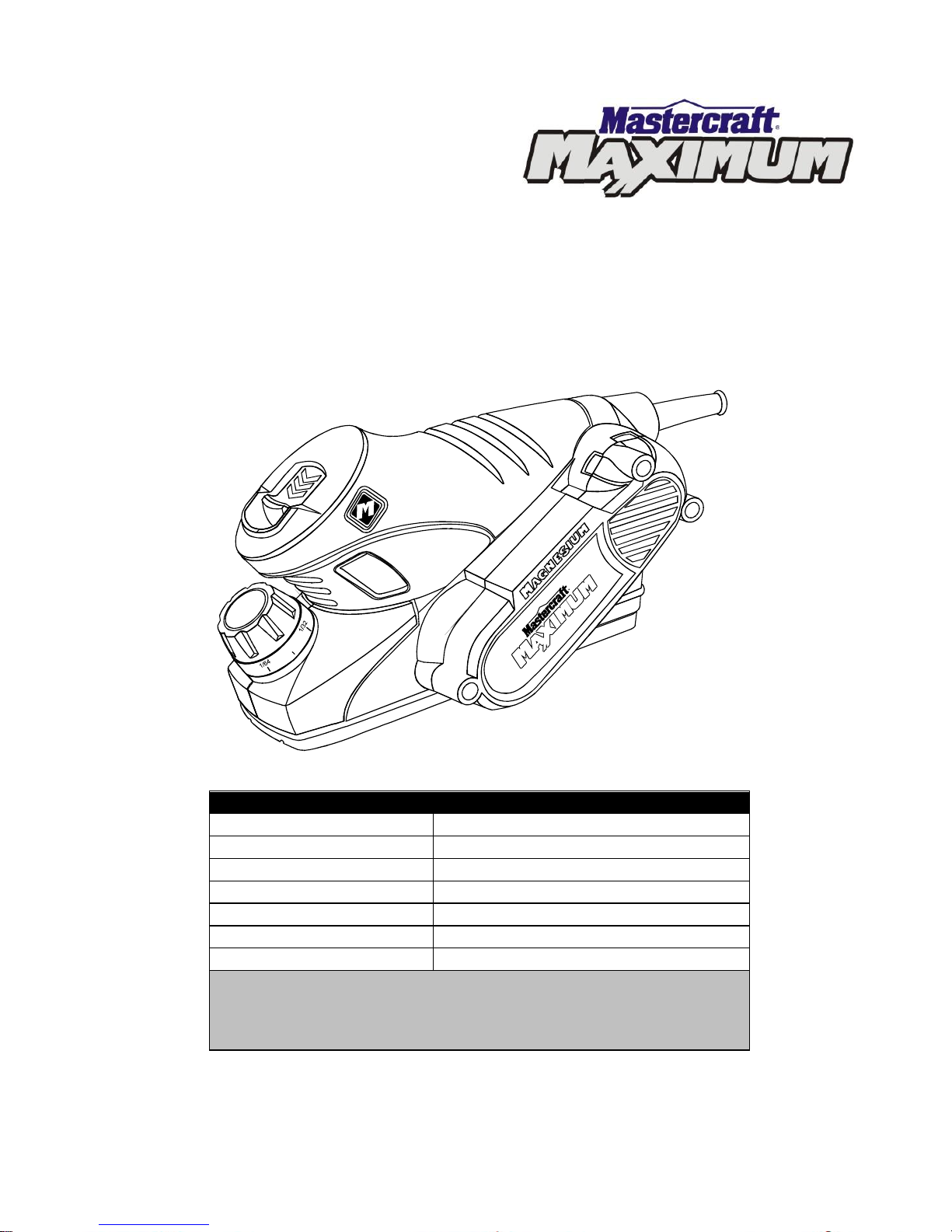
PALM PLANER
54-6621-8
Owner’s Manual
PRODUCT SPECIFICATIONS
Rating:
120 V 60 Hz AC
Amperes:
3.5 A
Blade speed:
13,000 RPM (no load)
Planing width:
2 3/8” (60 mm) maximum
Planing depth:
1/64" (.40 mm) to 1/16" (1.5 mm)
Blade type:
Reversible
Weight:
5 lb (2.3 kg)
NEED ASSISTANCE?
Call us on our toll-free Customer Support Line:
1-800-689-9928
Imported by Mastercraft Canada Toronto, Canada M4S 2B8
Page 2

2
Product specifications ………….…………………………………………………….
1
Table of contents ……………………………………………………………………...
2
General safety warnings ……………………………………………………………..
3–4
Eye, ear & lung protection ……………………………………………………………
3–4
Electrical safety ……………………………………………………………………….
4
Power tool safety ……………………………………………………………………...
5–6
General safety rules …………………………………………………………………..
5
Work area ………………………………………………………………….…………..
5
Electrical safety ……………………………………………………………………….
5
Personal safety ………………………………………………………………………..
5–6
Use and care of power tools .………………………………………………………..
6
Service …………………………………………………………………………………
6
Specific safety rules …………………………………………………………………..
7
Extension cord safety ………………………………………………………….……..
8
Symbols ………………………………………………………………………………..
9
Know your palm planer ……………………………………………………………….
10
Accessories ……………………………………………………………………………
10
Contents ……………………………………………………………………………….
11–12
Assembly and operating ……………………………………………………………..
13–22
Adjusting the depth of cut ……………………………………………………………
13
ON/OFF switch with lock-off …………………………………………………………
13–14
Planing …………………………………………………………………………………
15–16
Blade protection foot ………………………………………………………………….
16
Chamfering ………..…………………………………………………………………..
16
Rabbeting ……………………………………………………………………………...
17
Vacuum adaptor ………………………………………………………………………
17
Changing the drive belt ………………………………………………………………
17–19
Replacing the cutting blades ………………………………………………………...
19–22
Maintenance …………………………………………………………………………..
23
Exploded view …………………………………………………………………………
24
Parts list ………………………………………………………………………………..
25–26
Warranty ……………………………………………………………………….………
27–28
TABLE OF CONTENTS
Page 3
3
EYE, EAR & LUNG PROTECTION
This instruction manual includes the following:
General Safety Rules
Specific Safety Rules and Symbols
Functional Description
Assembly
Operation
Maintenance
Accessories
!
ALWAYS WEAR EYE PROTECTION THAT CONFORMS WITH CSA
REQUIREMENTS or ANSI SAFETY STANDARD Z87.1
FLYING DEBRIS can cause permanent eye damage. Prescription
eyeglasses ARE NOT a replacement for proper eye protection.
WARNING: Non-compliant eyewear can cause serious injury if
broken during the operation of a power tool.
SAVE THESE INSTRUCTIONS FOR REFERENCE
WARNING: Use hearing protection, particularly during extended
periods of operation of the tool, or if the operation is noisy.
!
GENERAL SAFETY WARNINGS
CAUTION: Before using this tool or any of its accessories, read this
manual and follow all Safety Rules and Operating Instructions.
!
Page 4

4
ELECTRICAL SAFETY
WARNING: To avoid electrical hazards, fire hazards or damage to the
tool, use proper circuit protection.
This tool is wired at the factory for 110–120 V operation. It must be
connected to a 110–120 V, 15-A circuit that is protected by a time-delayed
fuse or circuit breaker. To avoid shock or fire, replace power cord
immediately if it is worn, cut or damaged in any way.
GENERAL SAFETY WARNINGS
WEAR A DUST MASK THAT IS DESIGNED TO BE USED WHEN
OPERATING A POWER TOOL IN A DUSTY ENVIRONMENT.
WARNING: Dust that is created by power sanding, sawing, grinding,
drilling, and other construction activities may contain chemicals that are
known to cause cancer, birth defects, or other genetic abnormalities. These
chemicals include:
Lead from lead-based paints
Crystalline silica from bricks, cement, and other masonry products
Arsenic and chromium from chemically treated lumber
The level of risk from exposure to these chemicals varies, according to how
often this type of work is performed. In order to reduce exposure to these
chemicals, work in a well-ventilated area, and use approved safety
equipment, such as a dust mask that is specifically designed to filter out
microscopic particles.
!
Page 5

5
GENERAL SAFETY RULES
WARNING: Read and understand
all instructions. Failure to follow all
instructions listed below may result in
electric shock, fire and/or serious personal
injury.
WORK AREA
Keep your work area clean and well lit.
Cluttered benches and dark areas invite
accidents.
Do not operate power tools in potentially
explosive environments, such as in the
presence of flammable liquids, gas or dust.
Power tools create sparks that may ignite
dust or fumes.
Keep bystanders, children and visitors
away while operating the tool. Distractions
can cause the operator to lose control.
ELECTRICAL SAFETY
Double insulated tools are equipped with a
polarized plug (one blade is wider than the
other). This plug will only fit into a
polarized plug one way.
If the plug does not fit into the outlet
properly, reverse the plug. If it still does not
fit, contact a qualified electrician to install a
polarized outlet. Do not alter the plug in
any way. Double insulation eliminates the
need for the three-pronged grounded
power cord and grounded power supply
system.
Avoid contact between the operator's body
and grounded surfaces such as pipes,
radiators, ranges, and refrigerators. There
is an increased risk of electric shock if the
operator's body is grounded.
Do not expose power tools to rain or wet
conditions. Water entering the power tool
will increase the risk of electric shock.
Do not abuse the cord. Do not use the
power cord to carry the tool or to pull the
plug out of the outlet. Keep the power cord
away from heat, oil, sharp edges, and
moving parts. Replace a damaged power
cord immediately. A damaged power cord
increases the risk of electric shock.
When operating a power tool outdoors,
use an outdoor-rated extension cord type
“W-A” or “W”. These cords are rated for
outdoor use and they reduce the risk of
electric shock.
PERSONAL SAFETY
Stay alert, be aware of the surroundings,
and use common sense when operating a
power tool. Do not use a power tool while
tired or under the influence of drugs,
alcohol, or medication. A moment of
inattention while operating a power tool
may result in serious personal injury.
Dress properly. Do not wear loose clothing
or jewellery.
Contain long hair. Keep hair, clothing, and
gloves away from moving parts. Loose
clothing, jewellery, or long hair can get
caught in moving parts.
!
POWER TOOL SAFETY
Page 6

6
PERSONAL SAFETY – cont’d
Avoid accidental start-ups. Verify that the
switch is in the OFF position before
plugging in the tool. Carrying a power tool
with a finger on the switch or plugging in a
tool that has the switch in the ON position
invites accidents.
Remove adjusting keys and wrenches
before turning the tool ON. A wrench or
key that is left attached to a rotating part of
the tool may result in personal injury.
Do not overreach. Keep proper footing and
balance at all times. Proper footing and
balance allows the operator to maintain
better control of the tool in unexpected
situations.
Use safety equipment. Always wear eye
protection.
Use a dust mask, non-skid safety shoes, a
hardhat, or hearing protection when
appropriate.
USE AND CARE OF POWER TOOLS
Use clamps or another practical means to
secure and support the workpiece to a
stable platform. Holding the work in a hand
or against the body is not stable, and may
lead to loss of control.
Do not force the tool. Use the correct tool
for the application. The correct tool will do
the job better and safer when used at the
rate that it was designed to work at.
Do not use a power tool if it cannot be
turned ON or OFF using the power switch.
A tool that cannot be controlled using the
switch is dangerous, and must be repaired.
Disconnect the plug from the outlet before
making any adjustments, changing
accessories, or storing the tool. Such
preventive safety measures reduce the risk
of accidental start-ups.
When power tools are not in use, store
them out of the reach of children or
untrained persons. Tools are dangerous in
the hands of untrained users.
Maintain tools with care. Keep cutting tools
sharp and clean. Properly maintained
cutting tools with sharp cutting edges are
less likely to bind, and are easier to
control.
Inspect the tool for misalignment or binding
of moving parts, broken parts, and any
other condition that may affect the
operation of the tool. If it is damaged, have
the tool serviced before using it. Many
accidents are caused by poorly maintained
tools.
Use only accessories that are
recommended by the manufacturer for this
model. Accessories that are suitable for
one tool may become hazardous when
used with another tool.
SERVICE
Tools servicing must be performed by
qualified personnel. Service or
maintenance performed by non-qualified
personnel could result in a risk of injury.
When servicing a tool, use only identical
replacement parts. Follow the instructions
in the Maintenance section of this Manual.
The use of unauthorized parts or failure to
follow the instructions in the Maintenance
section of this Manual may create a risk of
electric shock or injury.
POWER TOOL SAFETY
Page 7

7
WARNING: Know your palm
planer. Read the Instruction Manual
carefully. Learn the tool’s applications
and limitations, as well as the specific
potential hazards related to this tool.
Following this rule will reduce the risk of
electric shock, fire or serious injury.
Always wear eye protection. Any power
tool can throw foreign objects
into your eyes and cause
permanent eye damage.
ALWAYS wear safety goggles
(not glasses) that comply with ANSI safety
standard Z87.1. Everyday glasses have
only impact resistant lenses. They ARE
NOT safety glasses.
WARNING: Glasses or goggles
not in compliance with ANSI Z87.1
could cause serious injury when they
break.
Always wear hearing protection and a dust
mask. Use only in a well-ventilated area.
Using personal safety devices and working
in a safe environment reduces the risk of
injury.
DANGER: Always unplug the tool
from the power source before making
any adjustments or removing the
blades.
DANGER: Be extremely careful
when handling the cutting blades. They
are extremely sharp and can cause
serious injury.
DANGER: Always make sure the
blade clamping screws are correctly
tightened before using the planer.
DANGER: Use only Mastercraft®
replacement cutting blades. Any other
cutting blades may not be clamped
properly in the cylinder and could be
violently thrown, causing serious injury
to the operator.
DANGER: When turning the
planer ON, watch for excessive
vibration which could be caused by
loose or improperly installed cutting
blades.
Never use dull or damaged cutting blades.
Dull or damaged cutting blades require
more power to operate and could result in
overheating the motor. They will also result
in poor cutting action and a rough finish.
Always replace both blades at the same
time to maintain proper cylinder balance
and smooth cutting action.
Always make sure the work surface is free
of nails and other foreign objects. Cutting
into a nail can cause the tool to jump. It will
also damage the cutting blades.
Always use a safe method to secure the
workpiece. Use both hands to guide the
tool wherever possible. Never place hands
near the cutting blades.
Never lay the workpiece on hard surfaces
such as concrete, stone, etc. The tool may
jump if the cutting blades contact the hard
surface. The blades will also be damaged.
Make sure all rags, cords, string etc. are
removed from the work area. Any of these
items could be caught in the cutting blades
and cause loss of control over the tool.
Never operate the palm planer while
covering the air vents with your hands. The
motor will overheat.
SPECIFIC SAFETY RULES
! ! !
!
!
!
!
Page 8

8
When turning the switch ON, make sure
the cutting blades are not touching
anything, including the workpiece.
Always allow the motor to come up to its
full speed before attempting to use the
planer.
Do not allow your face to get too close to
the workpiece when operating the tool.
Wood chips can fly onto your face and
eyes.
Turn the tool OFF and wait for the cutting
blades to stop before setting the tool down.
Never take deep cuts or move the planer
into the workpiece too quickly. Either
action will reduce the motor speed and
cause the motor to overheat and produce
rough cutting action.
When setting tool down, either lay it on its
side or in its upright position with the blade
protection foot resting on a flat surface.
Use the dust extraction system wherever
practical to avoid creating excessive dust.
Never use your finger to remove wood
chips and saw dust from the chip chute. If
chips and saw dust from damp wood
become jammed in the chip chute, turn the
tool OFF, unplug it from the power source
and use a wooden stick to clean out the
chip chute.
WARNING: Keep the extension
cord clear of the work area. Position the
cord so it will not get caught on the
workpiece, a tool, or any other obstruction
while the power tool is in use.
If an extension cord is used with this palm
planer, verify that it is in good condition.
When using an extension cord, be sure to
use one that is heavy enough to carry the
current that the tool will draw. An
undersized cord will cause a drop in line
voltage, which will result in a loss of power
and overheating.
The following table shows the correct size
to use according to cord length and the
amperage rating that is listed on the tool's
nameplate. When in doubt, use the next
heavier gauge. The smaller the gauge
number, the heavier the cord.
Verify that the extension cord is properly
wired and in good condition. Replace a
damaged extension cord immediately, or
have it repaired by a qualified electrician
before using it. Keep the extension cord
away from sharp objects, excessive heat,
and damp or wet areas.
Use a separate electrical circuit for power
tools. This circuit must consist of not less
than 14 gauge wire and should be
protected by either a 15 A time-delayed
fuse or a circuit breaker. Before connecting
the power tool to the outlet, verify that the
switch is in the OFF position, and that the
voltage of the power source is the same as
the voltage that is indicated on the tool's
nameplate. Running this palm planer at
lower voltage will damage the motor.
SPECIFIC SAFETY RULES
EXTENSION CORD
SAFETY
MINIMUM GAUGE (AWG) EXTENSION
CORDS
(120 V use only)
Ampere Rating
Total length in feet
More
Than
Not
More
Than
25’ 50’ 100’ 150’
0 6 18
16
16
14
6
10
18
16
14
12
10
12
16
16
14
12
12
16
14
12
Not Applicable
!
Page 9
9
V
Volts
A
Amperes
Hz
Hertz
W
Watts
kW
Kilowatts
Microfarads
L
Litres
kg
Kilograms
H
Hours
N/cm2
Newtons per square
centimetre
Pa
Pascals
Min
Minutes
S
Seconds
Alternating current
Three-phase alternating
current
Three-phase alternating
current with neutral
Direct current
No load speed
Alternating or direct
current
Class II construction
Splash-proof
construction
Watertight construction
Protective grounding at
grounding terminal,
Class I tools
Revolutions or
reciprocations per
minute
Diameter
Off position
Arrow
Warning symbol
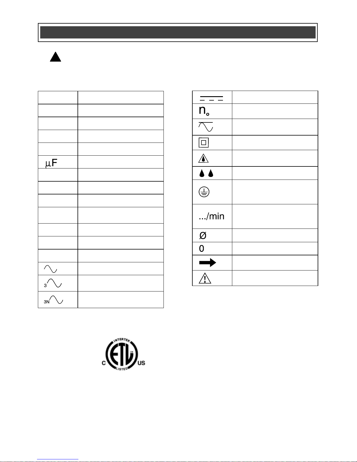
SYMBOLS
WARNING: Some of the following symbols may appear on the palm
planer. Study these symbols and learn their meaning. Proper interpretation of
these symbols will allow for more efficient and safer operation of this tool.
!
This symbol designates that this tool is
listed with Canadian requirements by ETL
Testing Laboratories, Inc.
Conforms to UL STD. 73
Certified to CAN/CSA STD. C22.2 No. 12
3042597
HOMOLOGUÉ
Page 10

10
Main
handle
AVAILABLE ACCESSORIES
WARNING: Use only accessories
that are recommended for this palm
planer. Follow the instructions that
accompany the accessories. The use of
improper accessories may result in
injury to the operator or damage to the
palm planer.
Before using any accessory, carefully read
the instructions or the Owner’s Manual for
the accessory.
Replacement cutting blades
WARNING: If any part is missing or
damaged, do not plug the tool into the
power source until the missing or damaged
part is replaced.
KNOW YOUR PALM PLANER
ACCESSORIES
!
!
On/Off
switch
Depth adjustment
knob
Fixed sole
plate
Air vents
Lock-off
Button
Moveable
sole plate
Drive belt
cover
Page 11

11
CONTENTS
Carefully unpack the palm planer.
Compare the contents against the “PALM
PLANER COMPONENTS” chart at right.
NOTE: See illustration of palm planer on
Page 12.
WARNING: To avoid fire or toxic
reaction, never use gasoline, naphtha,
acetone, lacquer thinner or similar
highly volatile solvents to clean the
tool.
!
CONTENTS
PALM PLANER COMPONENTS
KEY
DESCRIPTION
QTY
A
Palm planer
1
B
2.5 mm Hex key
1
C
Cutting blade wrench
1
D
Replacement drive belt
1
E
Vacuum adapter
1
F
Blow moulded case
1
Owner’s manual
1
Page 12

12
CONTENTS
Page 13

13
ADJUSTING THE DEPTH OF CUT
The depth of cut can be set anywhere
between 1/64” (0.40 mm) and 1/16”
(1.5 mm).
To set the cutting depth, rotate the depth
adjustment knob (1) to the desired cutting
depth (Fig. 1). To increase the cutting
depth, turn the knob clockwise. To
decrease the cutting depth, turn the knob
counter clockwise.
NOTES:
a) When leaving the tool unattended or
when storing the tool, set the cutting
depth knob to “P”. This setting will
ensure the cutting blades are fully
retracted from the sole plate surface.
b) The depth indicators on the depth
adjustment knob are approximations
only. Always make a test cut on a
scrap workpiece to verify the correct
amount of material is being removed.
ON/OFF SWITCH WITH LOCK-OFF
This tool is equipped with an ON/OFF
switch and LOCK-OFF button to prevent it
from being accidentally started when the
ON/OFF switch is pressed.
1. To turn the tool ON, grasp the planer
handle with your right hand and slide
the lock-off switch (1) forward
(Fig. 2).
2. While holding the lock-off switch
forward, press the upper portion of the
ON/OFF button (2) into the tool handle
with your thumb.
ASSEMBLY AND OPERATING
Fig. 1
Fig. 2
Page 14

14
ON/OFF SWITCH WITH LOCK OFF – cont’d
3. When the tool starts, you can release
the lock-off switch while continuing to
press inward on the ON/OFF button.
The tool will continue to run.
4. To turn the tool OFF, remove your
thumb from the ON/OFF button.
NOTE: Once the tool has stopped, you
must repeat steps 1 & 2 to turn it ON
again.
For safety reasons, the operator
must read the sections of this
Instruction Manual entitled
“GENERAL SAFETY WARNINGS”,
“POWER TOOL SAFETY”,
“SPECIFIC SAFETY RULES”,
“EXTENSION CORD SAFETY” and
“SYMBOLS” before using this palm
planer.
Verify the following every time the
palm planer is used:
1. Safety glasses, safety goggles,
or face shield is being worn.
2. Hearing protection and dust
mask are being worn.
3. The cutting blades are in good
condition, and are properly
tightened into the cylinder.
4. The power cord is clear of the
cutting blade path.
5. The workpiece is clear of any
foreign materials such as nails.
Failure to observe these safety rules
will significantly increase the risk of
injury.
WARNING
!
ASSEMBLY AND OPERATING
Page 15

15
PLANING
WARNING: Use two hands on the
planer when practical.
WARNING: Where possible,
clamp the workpiece to a stable
platform such as a work bench.
1. Adjust depth of cut.
2. Rest the front sole plate (1) on the
workpiece (2) (Fig. 3).
NOTE: Make sure the cutting blades do
NOT contact the workpiece.
3. Turn the tool ON and wait for the
cutting blades to reach full speed.
4. While holding the tool firmly, slowly
move the tool forward while applying
slight pressure to the front of the tool.
5. As you near the end of the forward
planing stroke, use your right hand to
apply slight downward pressure to the
rear of the tool. This action will ensure
a smooth consistent cutting depth as
the cutting blades leave the
workpiece.
NOTE: Do not allow the front of the planer
to tilt downward as the cutting blades leave
the workpiece. A deeper cut will result.
6. Push the planer forward until the
cutting blades move beyond the
workpiece.
NOTES:
a) For better control of the planer, incline
the workpiece slightly away from you
so you plane “downhill”.
ASSEMBLY AND OPERATING
!
!
Fig. 3
Page 16

16
PLANING – cont’d
NOTES:
b) Moving the plane too quickly or
removing too much material in one
pass will result in poor quality of cuts
and possibly damage to the motor. It
is always better to remove the material
in small amounts using more passes
to complete the work.
c) Moving the planer too slowly may
cause the blades to burn or mar the
surface.
d) The proper feed rate will be dictated
by the depth of cut, the type of wood,
and the moisture content of the wood
being planed. Make practice cuts on a
scrap workpiece of the same material
as the good workpiece to establish the
correct cutting depth and feed rate.
BLADE PROTECTION FOOT
Between planning operations, you can rest
the planer on a flat surface with the blade
protection foot (1) in the downward
position (Fig. 4).
NOTE: The blade protection foot will
automatically fall into the “down” position
when the cut is complete and be pushed to
its upward position (2) when the planer is
moved forward on the workpiece.
CHAMFERING
To chamfer the corner of the workpiece,
align one of the three “V” grooves (1) with
the corner of the workpiece (2) (Fig. 5).
NOTE: The “V” grooves are different
depths. Select the “V” groove that will
produce the desired chamfer.
!
ASSEMBLY AND OPERATING
Fig. 4
Fig. 5
Page 17

17
RABBETING
1. Draw a pencil line (1) at the desired
depth of the rabbet (Fig. 6).
2. Make the first cut with the right hand
edge of the sole plate aligned with the
pencil line.
3. Make the next cut with the sole plate
sliding along the edge left by the first
cut (Fig. 7).
4. Continue making successive cuts until
the desired depth of rabbet is
achieved.
VACUUM ADAPTER
The vacuum adapter can be installed for
use with a workshop vacuum.
1. Push the small end of the vacuum
adapter (1) into the vacuum port (2)
located on the right hand side of the
palm planer (Fig. 8).
NOTE: Twist the vacuum adapter to
ensure the two locking knobs (3) click into
the two matching holes (4) in the vacuum
port.
2. To remove the vacuum adapter, twist
and pull it from the vacuum port of the
tool.
CHANGING THE DRIVE BELT
After several hours of use, the drive
belt may become worn or break.
WARNING: Remove the plug from
the power source.
ASSEMBLY AND OPERATING
Fig. 6
Fig. 8
!
Fig. 7
Page 18

18
CHANGING THE DRIVE BELT – cont’d
1. Turn the tool on its right hand side on
a table or work bench.
WARNING: Be extremely careful
not to touch the cutting blades with
your hands. Serious injury may result.
2. Remove three belt cover screws (1)
from the belt cover (2) using a #2
screwdriver (Fig 9).
3. Pull the belt cover away from the
planer housing (3).
4. If the belt is broken, remove it from the
pulley area. If the belt is NOT broken,
insert one finger under the belt (4)
about 1” (2.54 cm) from the large drive
pulley (5) and pull upward on the belt
(Fig. 10).
5. While pulling upward on the belt, pull it
toward the large pulley. The belt will
climb upward on the pulley as the
pulley rotates.
6. Repeat steps #4 & #5 until the belt is
completely removed from both pulleys.
7. Remove all loose debris from the belt
housing and belt housing cover.
NOTE: Use a clean DRY soft brush. Never
use any solvent or water as you will
damage the tool.
8. Place the belt on the small pulley (6)
(Fig. 11).
NOTE: Make sure the belt fits fully into all
the grooves in the small pulley.
ASSEMBLY AND OPERATING
!
Fig. 11
Fig. 9
Fig. 10
Page 19

19
CHANGING THE DRIVE BELT – cont’d
9. Place the belt on the edge of the large
pulley (7).
10. Press downward on the belt about
1” (2.54 cm) from the pulley (8).
11. Rotate the pulley while pressing down
on the belt, moving your finger toward
the large pulley.
12. Repeat steps #10 & #11 until the belt
is fully installed on the large pulley.
NOTE: Once the belt is fully installed on
the large pulley, rotate the pulleys and
check to make sure the belt is fully
engaged in ALL the grooves in BOTH the
large and small pulleys. If the belt is not
engaging all the grooves, it will damage
the tool and the belt will be ruined.
13. Replace the belt cover. Do not over
tighten the screws.
REPLACING THE CUTTING BLADES
WARNING: Exercise extreme
caution when handling the cutting
blades. Use small pliers to remove and
replace the blades in the blade cylinder.
WARNING: Remove the plug from
the power source.
Removing the blades
1. Place the tool on its back with the cord
end to your left hand side. It is best to
place the tool on a work bench that is
protected with an old towel to prevent
damaging the tool or blades.
ASSEMBLY AND OPERATING
!
!
Fig. 11
Page 20

20
REPLACING THE CUTTING BLADES – cont’d
Removing the blades – cont’d
2. Rotate the cylinder to expose one of
the blades (1) in the middle of the
opening between the front and rear
sole plates (Fig. 12).
3. Using the 30 mm blade screw wrench
(2), loosen all three blade clamp
screws (3) approximately 1 turn.
WARNING: Exercise extreme
caution when using the wrench on the
blade clamp screws. The blade is
extremely sharp and may cause serious
injury if the wrench slips or you touch
the blade.
NOTE: To loosen the blade clamp screws,
push the wrench AWAY from your body.
4. Carefully place the blade of a small
screwdriver (4) on the end of the
blade (5) and carefully and pry the
cutting blade away from the metal
blade stop (6) (Fig. 13).
NOTE: Pry the blade away from the metal
stop at least 1/8” (3 mm).
5. Use a small pair of pliers (7) to pull on
the exposed end of the cutting blade
(8) (Fig. 14). Slide the blade
completely out of the blade clamp (9).
6. Use a soft dry brush to clean all debris
out of the cutting blade clamp.
7. Repeat steps #2 through #6 to remove
the second blade from the blade
cylinder.
ASSEMBLY AND OPERATING
!
Fig. 12
Fig. 14
Fig. 13
Page 21

21
REPLACING THE CUTTING BLADES – cont’d
Installing the cutting blades
1. Rotate the cutting blade endways so
the sharp new cutting edge is facing
upward.
2. Carefully grasp the far end of the
cutting blade with a pair of small pliers
and slide the cutting blade, sharp side
up, into the cutting blade clamp where
the blade was removed.
NOTE: Make sure the grooved side of the
cutting blade is toward the rear of the tool
and the new sharp edge is upward.
3. Use a small piece of scrap wood to
gently push the blade fully into the
blade clamp until it comes to rest
against the metal blade stop.
4. Slightly tighten the MIDDLE blade
clamp screw (1) using the 30 mm
blade screw wrench (Fig. 15).
NOTE: Tighten the blade clamp screw by
pulling the wrench toward you. At this
point, only tighten the blade clamp screw
SLIGHTLY.
5. Using a small piece of soft wood,
carefully tap the ends of the blade to
ensure it is exactly parallel with the
front sole plate, blade cylinder and
blade clamp.
NOTE: If the blade is not parallel with the
front sole plate, the planning action will not
be square.
ASSEMBLY AND OPERATING
Fig. 15
Page 22

22
REPLACING THE CUTTING BLADES – cont’d
Installing the cutting blades – cont’d
6. When you have made the cutting
blade parallel to the front sole plate,
SLIGHTLY tighten the two outer blade
clamp screws (2 and 3).
7. Recheck the blade alignment and
make any necessary adjustments.
8. Completely tighten the MIDDLE blade
clamp screw first, and then completely
tighten the two outer blade clamp
screws.
9. Recheck the blade alignment to make
sure the blade did not move while
tightening the blade clamp screws. If
the blade requires realignment, repeat
steps #4 through #8.
10. Repeat steps #1 through #9 to install
the second cutting blade.
DANGER: Make sure all three of
the blade clamp screws are fully
tightened before turning the tool ON.
When turning the tool ON, always have
the cutting blades and sole plate facing
away from your body. Loose cutting
blades will be thrown violently and
possibly cause serious injury.
11. Turn the tool ON. If there are any
unusual sounds or vibrations, turn the
tool OFF immediately and check for
misaligned or damaged cutting
blades.
ASSEMBLY AND OPERATING ASSEMBLY AND OPERATING
!
Fig. 15
Page 23

23
GENERAL
WARNING: When servicing, use
only identical replacement parts. The
use of any other part may create a
hazard or cause product damage.
DO NOT use solvents when cleaning
plastic parts. Plastics are susceptible to
damage from various types of commercial
solvents and may be damaged by their
use. Use a clean cloth to remove dirt, dust,
oil, grease etc.
WARNING: Do not allow brake
fluids, gasoline, petroleum-based
products, penetrating oils, etc. to come
into contact with plastic parts. They
contain chemicals that can damage,
weaken or destroy plastic.
DO NOT abuse power tools. Abusive
practices can damage the tool and the
workpiece.
WARNING: DO NOT attempt to
modify tools or create accessories. Any
such alteration or modification is
misuse and could result in a hazardous
condition leading to possible serious
injury. It will also void the warranty.
LUBRICATION
All of the bearings in this tool are
lubricated with a sufficient amount of highgrade lubricant for the life of the unit under
normal conditions. Therefore, no further
lubrication is required.
MAINTENANCE
! ! !
Page 24

24
EXPLODED VIEW
Page 25

25
WARNING: When servicing, use only Mastercraft
®
replacement parts. The use of
any other parts may create a safety hazard or cause damage to the palm planer.
Any attempt to repair or replace electrical parts on this palm planer may create a safety
hazard unless repairs are performed by a qualified technician. For more information, call
the Toll-free Helpline, at 1-800-689-9928.
Always order by PART NUMBER, not by key number.
Key #
Part #
Part Name
Quantity
1
9402120101
Label 1 2
5200100101
Left decorative plate
1
3
4400090101
Switch button
1
4
5500020101
Spring
1
5
4300060101
Left housing
1
6
5500030101
Safety button spring
1
7
4400170101
Safety button spring
1
8
6601030503
Flat washer
1
9
6411290813
Tapping screw ST 2.9x8
1
10
5400060101
Switch on/off plate
1
11
6416290913
Tapping screw ST 2.9x8
4
12
3500070101
Terminal
1
13
2700030101
Micro switch
1
14
5200080101
Front sole plate
1
15
5500040101
Depth adjustment spring
1
16
4400120101
Guide seat
1
17
5800010101
Depth adjustment nut
1
18
6600190101
Small copper cap
1
19
5500050101
Small spring
1
20
4400180101
Depth adjustment knob
1
21
6610041003
Spring washer 4x1
1
22
6511400813
Screw M4x8
1
23
4400160101
Depth adjustment knob cover
1
24
4300050101
Right housing
1
25
5200110101
Right decorative plate
1
26
6601060503
Flat washer
2
27
6610030803
Spring washer 3
2
28
6511302313
Screw M3x30
2
29
6411291623
Tapping screw ST2.9x16
9
30
6801080121
Bearing 608RS
2
31
4400080101
Dust baffle
1
32
4400130101
Mounting plate
2
PARTS LIST
!
Page 26

26
Key #
Part #
Part Name
Quantity
33
5200040101
Blade roller
1
34
6712050803
Hex bolt
6
35
5400100101
Blade clamping plate
2
36
5400110101
Blade fixing plate
2
37
5200050101
Blade 2 38
6515500813
Set screw
4
39
5400080101
Protection plate
1
40
6300020101
Roller shaft
1
41
4400100101
Dust sleeve
1
42
6411391213
Tapping screw ST3.9x12
2
43
5400070101
Cord clamp
1
44
4600020101
Cord guard
1
45
7266050304
Cord set
1
46
6801100121
Bearing 6000RS
1
47
5400050101
Bearing hold down
1
48
6411391013
Tapping screw ST3.9x10
6
49
6200030101
Belt wheel
1
50
6701080502
Hex nut M8
1
51
4600070101
Belt
1
52
5200120101
Belt cover
1
53
6411391413
Tapping screw ST3.9x19
3
54
3800030101
Stator
1
55
6801070321
Bearing 607RS
1
56
5613050101
Carbon brush
2
57
5615030101
Brush holder
2
58
5612030101
Brush holder support
2
59
3700030101
Rotor
1
60
6200020101
Motor gear
1
61
6701050403
Hex nut M5
1
62
6200040101
Motor belt wheel
1
63
5200060101
Gearbox
1
64
6801080221
Bearing 628RS
2
65
6300010101
Output shaft
1
66
6932102501
Woodruff key
1
67
6200010101
Big gear
1
68
6613090803
Retaining ring
1
69
5200070101
Gearbox cover
1
70
6411394513
Tapping screw ST3.9x45
3
71
5200090101
Back sole plate
1
72
4400140101
Rest foot
1
73
4400150101
Dust port
1
74
5402080101
Spanner
1
PARTS LIST
Page 27

27
5-Year Limited Warranty
This Mastercraft® Maximum® product is guaranteed for a period of five (5) years
from the date of original retail purchase against defects in workmanship and
materials, except for the following components:
a) Component A: Batteries, chargers and carrying cases, which are
guaranteed for a period of two (2) years from the date of original retail
purchase against defects in workmanship and materials;
b) Component B: Accessories which are guaranteed for a period of one (1)
year from the date of original retail purchase against defects in
workmanship and materials.
Subject to the conditions and limitations described below, this product, if returned to
us with proof of purchase within the stated warranty period and if covered under this
warranty, will be repaired or replaced (with the same model, or one of equal value or
specification),at our option. We will bear the cost of any repair or replacement and
any costs of labour relating thereto.
These warranties are subject to the following conditions and limitations:
a) A bill of sale verifying the purchase and purchase date must be provided;
b) This warranty will not apply to any product or part thereof that is worn or
broken or that has become inoperative due to abuse, misuse, accidental
damage, neglect or lack of proper installation, operation or maintenance
(as outlined in the applicable owner’s manual or operating instructions) or
that is being used for industrial, professional, commercial or rental
purposes;
c) This warranty will not apply to normal wear and tear or to expendable parts
or accessories that may be supplied with the product that are expected to
become inoperative or unusable after a reasonable period of use;
d) This warranty will not apply to routine maintenance and consumable items,
including but not limited to fuel, lubricants, vacuum bags, blades, belts,
sandpaper, bits, fluids, tune-ups or adjustments;
e) This warranty will not apply where damage is caused by repairs made or
attempted by others (i.e.: persons not authorized by the manufacturer);
f) This warranty will not apply to any product that was sold to the original
purchaser as a reconditioned or refurbished product (unless otherwise
specified in writing);
Page 1 of 2
Page 28

28
Imported by Mastercraft Canada Toronto, Canada M4S 2B8
Rev 1.2 08/05/2008
5-Year Limited Warranty – cont’d
These warranties are subject to the following conditions and limitations:
g) This warranty will not apply to any product or part thereof if any part
from another manufacturer is installed therein or any repairs or
alterations have been made or attempted by unauthorized persons;
h) This warranty will not apply to normal deterioration of the exterior
finish including but not limited to scratches, dents, paint chips, or to
any corrosion or discolouring by heat, abrasive and chemical cleaners;
and
i) This warranty will not apply to component parts sold by and identified
as the product of another company, which shall be covered under the
product manufacturer’s warranty, if any.
Additional Limitations
This warranty applies only to the original purchaser, and cannot be transferred.
Neither the retailer nor the manufacturer shall be liable for any other expense, loss
or damage, including but not limited to any indirect, incidental, consequential or
exemplary damages arising in connection with the sale, use or inability to use this
product.
Notice to Consumer
This warranty gives you specific legal rights, and you may have other rights, which
may vary from province to province. The provisions contained in this warranty are
not intended to limit, modify, take away from, disclaim or exclude any statutory
warranties set forth in any applicable provincial or federal legislation.
Mastercraft® is a superior line of products selected for their workmanship and
materials. These products are designed to meet rigorous quality and performance
standards, and are approved by our Quality Assurance laboratory.
TOLL-FREE HELPLINE: 1-800-689-9928
Page 2 of 2
 Loading...