

Page 1
Multi-attachment Rotary Tool System
54-4790-6
Owner’s Manual
Imported by Trileaf Distribution Trifeuil Toronto, Canada M4S 2B8
SPECIFICATIONS
Motor:
Permanent magnet, 120 V AC, 60 Hz, 2 A
Variable speeds:
5,000 to 35,000 RPM (no load)
Collets:
1/8, 3/32, 1/16" (3, 2.5, 1.5 mm)
Weight:
1 lb 12 oz (780 g)
TOLL FREE HELPLINE 1-800-689-9928
Page 2

2
Specifications ………….…………………………………………………………………..
1
Table of contents …………………………………………………………………….……
2
Safety warnings …………………………………………………………………………...
3–4
Eye, ear, and lung protection ……………………………………………………. ……..
3–4
Electrical safety ……………………………………………………………….. …………
4
Power tool safety ……………………………………………………………………….…
5–6
General safety rules …………………………………………………………... ………..
5
Work area ………………………………………………………………….…... …………
5
Electrical safety ……………………………………………………………….. …………
5
Personal safety ……………………………………………………………….. ………….
5–6
Use and care of power tools……………………………………………………………..
6
Service …………………………………………………………………………… ……….
6
Specific safety rules ………………………………………………………………………
7
Extension cord safety ……………………………………………………………….……
8
Symbols ……………………………………………………………………………………
9
Diagram and location of parts …………………………………………………………...
10–11
Accessories and Contents …………………………………………………………….. ..
12
Accessories ……………………………………………………………………………….
12
Contents ……………………………………………………………………………………
12–13
Contents of the accessory kit ……………………………………………………………
14–16
Description and use of the accessory kit……………………………………………….
16–17
Assembly and Operating instructions …………………………………………………..
18–35
Changing the collet ……………………………………………………….….…………...
18
Installing accessories …………………………………………………………. ………...
18–19
Connecting the flexible shaft to the tool …………………………………….. ………...
19–20
Changing the collet and accessories in the flexible shaft ……………….…... ………
20
Assembling the rotary tool stand ………………………………………………. ………
21
Installing the right angle attachment ………………………………………… ………...
22–23
Installing the angle guide and the vacuum adapter ………………………………. ….
23–24
Installing the sander attachment …………………………………………….. …………
24–25
Installing sandpaper …………………………………………………………... ………...
26
Installing the pad onto the sander ………………………………………………………
26–27
Sanding wood ……………………………………………………………………………..
27
Sanding tips ……………………………………………………………………………….
27–28
Installing the mini circular saw attachment …………………………………………….
28–29
Installing a saw blade …………………………………………………….….…………...
30
Cutting wood ………………………………………………………………….…………...
31–32
Assembling the LED worklight …………………………………………………………..
32
Selecting the proper speed…………………………….…………………………………
33
Digital motor control ………………………………………………………….…………...
34
ON/OFF switch ……………………………………………………………….…………...
34
Adjusting the speed ………………………………………………………………………
34–35
Speed memory ……………………………………………….…………………………...
35
Maintenance ……………………………………………………………………………….
36
Exploded view ……………………………………………………………………………..
37
Parts list ……………………………………………………………………………………
38
Warranty ……………………………………………………………………….…………..
39
TABLE OF CONTENTS
Page 3

3
EYE, EAR, AND LUNG PROTECTION
This Owner's Manual contains the following information:
General Safety Rules
Specific Safety Rules and Symbols
Functional Description
Assembly Instructions
Operating Instructions
Maintenance
Accessories
!
WEAR EYE PROTECTION THAT CONFORMS WITH CSA
REQUIREMENTS or ANSI SAFETY STANDARD Z87.1
FLYING DEBRIS can cause permanent eye damage. Prescription
eyeglasses ARE NOT a replacement for proper eye protection.
WARNING: Non-compliant eyewear can cause serious injury if
it breaks while the wearer is operating a power tool.
KEEP THIS OWNER'S MANUAL IN A SAFE PLACE FOR FUTURE REFERENCE
WARNING: Use hearing protection, especially when operating the tool
for an extended period and when performing a noisy operation.
!
SAFETY WARNINGS
CAUTION: Read this Owner's Manual carefully before using this tool or
any of its accessories, and follow all Safety Rules and Operating
instructions.
!
Page 4
4
ELECTRICAL SAFETY
WARNING: Use proper circuit protection in order to avoid electrical
hazards, fire hazards, or damage to the rotary tool.
This rotary tool is wired at the factory for 110–120 V operation. It must be
connected to a 110–120 V 15 A time-delayed fuse or circuit breaker. In order
to avoid shock or fire, replace the power cord immediately if it is worn, cut, or
damaged in any way.
WEAR A DUST MASK THAT IS DESIGNED TO BE USED WHEN
OPERATING A POWER TOOL IN A DUSTY ENVIRONMENT.
WARNING: Dust that is created by power sanding, sawing, grinding,
drilling, and other construction activities may contain chemicals that are
known to cause cancer, birth defects. or other genetic abnormalities. These
chemicals include:
Lead from lead-based paints
Crystalline silica from bricks, cement, and other masonry products
Arsenic and chromium from chemically-treated lumber
The level of risk from exposure to these chemicals varies according to how
often this type of work is performed. In order to reduce exposure to these
chemicals, work in a well-ventilated area, and use approved safety
equipment, such as a dust mask that is specifically designed to filter out
microscopic particles.
!
SAFETY WARNINGS
Page 5

5
GENERAL SAFETY RULES
WARNING: Read all instructions
carefully and understand them
completely. Failure to follow all of the
instructions listed below may result in
electric shock, fire, and/or serious personal
injury.
WORK AREA
Keep the work area clean and well lit.
Cluttered benches and dark areas invite
accidents.
Do not operate a power tool in a potentially
explosive environment, such as in the
presence of flammable liquids, gas, or
dust. Power tools create sparks that may
ignite the dust or fumes.
Keep bystanders, children, and visitors
away while operating a power tool.
Distractions can cause the operator to lose
control.
ELECTRICAL SAFETY
Double insulated tools are equipped with a
polarized plug (one blade is wider than the
other). This plug will only fit into a
polarized outlet one way.
If the plug does not fit into the outlet
properly, reverse the plug. If it still does not
fit, contact a qualified electrician in order to
install a polarized outlet. Do not alter the
plug in any way. Double insulation
eliminates the need for the three-pronged
grounded power cord and grounded power
supply system.
Avoid contact between the operator's body
and grounded surfaces such as pipes,
radiators, ranges, and refrigerators. There
is an increased risk of electric shock if the
operator's body is grounded.
Do not expose power tools to rain or wet
conditions. Water entering the power tool
will increase the risk of electric shock.
Do not abuse the cord. Do not use the
power cord to carry the tool or to pull the
plug out of the outlet. Keep the power cord
away from heat, oil, sharp edges, and
moving parts. Replace a damaged power
cord immediately. A damaged power cord
increases the risk of electric shock.
When operating a power tool outdoors,
use an outdoor extension cord that is
marked “W-A” or “W”. These cords are
rated for outdoor use, and they reduce the
risk of electric shock.
PERSONAL SAFETY
Stay alert, be aware of the surroundings,
and use common sense when operating a
power tool. Do not use a power tool while
tired or under the influence of drugs,
alcohol, or medication. A moment of
inattention while operating a power tool
could result in serious personal injury.
Dress properly. Do not wear loose clothing
or jewellery.
Contain long hair. Keep hair, clothing, and
gloves away from moving parts. Loose
clothing, jewellery, or long hair can get
caught in moving parts.
!
POWER TOOL SAFETY
Page 6

6
PERSONAL SAFETY – cont’d
Avoid accidental start-ups. Verify that the
switch is in the OFF position before
plugging the tool in. Carrying a power tool
with a finger on the switch or plugging in a
tool that has the switch in the ON position
invites accidents.
Remove adjusting keys and wrenches
before turning the tool ON. A wrench or
key that is left attached to a rotating part of
the tool may result in personal injury.
Do not overreach. Keep proper footing and
balance at all times. Proper footing and
balance allows the operator to maintain
better control of the tool in unexpected
situations.
Use safety equipment. Always wear eye
protection.
Use a dust mask, non-skid safety shoes, a
hardhat, or hearing protection when
appropriate.
USE AND CARE OF POWER TOOLS
Use clamps or another practical means to
secure and support the workpiece to a
stable platform. Holding the work in a hand
or against the body is not stable, and may
lead to loss of control.
Do not force the tool. Use the correct tool
for the application. The correct tool will do
the job better and safer when it is used at
the rate that it was designed to work at.
Do not use a power tool if it cannot be
turned ON or OFF using the power switch.
A tool that cannot be controlled using the
switch is dangerous, and must be repaired.
Disconnect the plug from the outlet before
making any adjustments, changing
accessories, or storing the tool. Such
preventive safety measures reduce the risk
of accidental start-ups.
When power tools are not in use, store
them out of the reach of children and other
untrained persons. Tools are dangerous in
the hands of untrained users.
Maintain tools with care. Keep cutting tools
sharp and clean. Properly maintained
cutting tools with sharp cutting edges are
less likely to bind, and are easier to
control.
Inspect the tool for misalignment or binding
of moving parts, broken parts, and any
other condition that may affect the
operation of the tool. If it is damaged, have
the tool serviced before using it. Many
accidents are caused by poorly maintained
tools.
Use only accessories that are
recommended by the manufacturer for this
model. Accessories that are suitable for
one tool may become hazardous when
used with another tool.
SERVICE
Tools must be serviced by qualified
personnel. Service or maintenance
performed by non-qualified personnel
could result in a risk of injury.
When servicing a tool, use only identical
replacement parts. Follow the instructions
in the Maintenance section of this Manual.
The use of unauthorized parts, or failure to
follow the instructions in the Maintenance
section of this Manual may create a risk of
electric shock or injury.
POWER TOOL SAFETY
Page 7

7
WARNING: For safety reasons,
read this Owner's Manual carefully and
understand it thoroughly before
plugging in the rotary tool.
Hold the tool by the insulated gripping
surfaces when performing any operation
where the cutting tool may coming into
contact with hidden wiring or its own power
cord. Contact with a “live” wire will make
the exposed metal parts of the tool “live”,
which could shock the operator.
Verify that the work surface is free of nails
and other foreign objects. Cutting into a
nail may cause the bit and the tool to jump,
and could damage the bit.
Do not hold the workpiece in one hand and
the tool in the other hand while using the
tool. Do not place the hands near or below
the cutting surface. It is much safer to
clamp the material and to guide the tool
using both hands.
Do not lay the workpiece on a hard surface
such as concrete, stone, etc. The
protruding cutting bit may cause the tool to
jump.
Wear safety goggles and a dust mask.
Work only in a well-ventilated area. Using
personal safety devices and working in a
safe environment reduces the risk of injury.
Verify that the collet nut and all other
adjustment devices are securely tightened
after changing bits and accessories or
making adjustments. Loose adjustment
devices may be thrown violently when the
tool is turned ON.
Be sure to use the correct collet size. If the
collet size is larger than the accessory's
shank, it will not grip the shank properly,
which could result in injury to the operator
or damage to the tool.
Inspect accessory bits, grinding stones,
cut-off wheels, etc. for damage before
each use. A damaged accessory can
break during use, which could cause
serious injury.
Do not use dull or damaged bits. Handle
sharp bits with care. A damaged bit can
snap during use. A dull bit requires more
force in order to push the tool, which could
cause the bit to break.
Do not touch the bit during or immediately
after use. After use, the bit is hot enough
to burn bare skin.
Do not operate the flexible shaft with a
bend radius of less that 6” (15.2 cm). A
shorter bend radius will damage the
flexible shaft and the motor of the rotary
tool.
SPECIFIC SAFETY RULES
!
Page 8

8
WARNING: Keep the extension
cord clear of the work area. Position the
cord so that it will not get caught on the
workpiece, a tool, or any other obstruction
while the power tool is in use.
If an extension cord is used with this rotary
tool, verify that it is in good condition.
When using an extension cord, be sure to
use one that is heavy enough to carry the
current that the tool will draw. An
undersized cord will cause a drop in line
voltage, which will result in a loss of power
and overheating.
The following table shows the correct size
to use according to cord length and the
amperage rating that is listed ton the tool's
nameplate. When in doubt, use the next
heavier gauge. The smaller the gauge
number, the heavier the cord.
Verify that the extension cord is properly
wired and in good condition. Replace a
damaged extension cord immediately, or
have it repaired by a qualified electrician
before using it. Keep the extension cord
away from sharp objects, excessive heat,
and damp or wet areas.
Use a separate electrical circuit for power
tools. This circuit must consist of not less
than 14 gauge wire, and should be
protected by either a 15 A time-delayed
fuse or a circuit breaker. Before connecting
the power tool to the outlet, verify that the
switch is in the OFF position, and that the
voltage of the power source is the same as
the voltage that is indicated on the tool's
nameplate. Running this rotary tool at
lower voltage will damage the motor.
MINIMUM GAUGE (AWG) EXTENSION
CORDS
(120 V use only)
Ampere Rating
Total length in feet
More
Than
Not
More
Than
25’ 50’ 100’ 150’ 0 6
18
16
16
14 6 10
18
16
14
12
10
12
16
16
14
12
12
16
14
12
Not Applicable
!
EXTENSION CORD SAFETY
Page 9
9
V
Volts
A
Amperes
Hz
Hertz
W
Watts
kW
Kilowatts
Microfarads
L
Litres
kg
Kilograms
H
Hours
N/cm2
Newtons per square
centimeter
Pa
Pascals
Min
Minutes
S
Seconds
Alternating current
Three-phase alternating
current
Three-phase alternating
current with neutral
Direct current
No load speed
Alternating or direct
current
Class II construction
Splash-proof
construction
Watertight construction
Protective grounding at
earthing terminal, Class I
tools
Revolutions or
reciprocations per
minute
Diameter
Off position
Arrow
Warning symbol
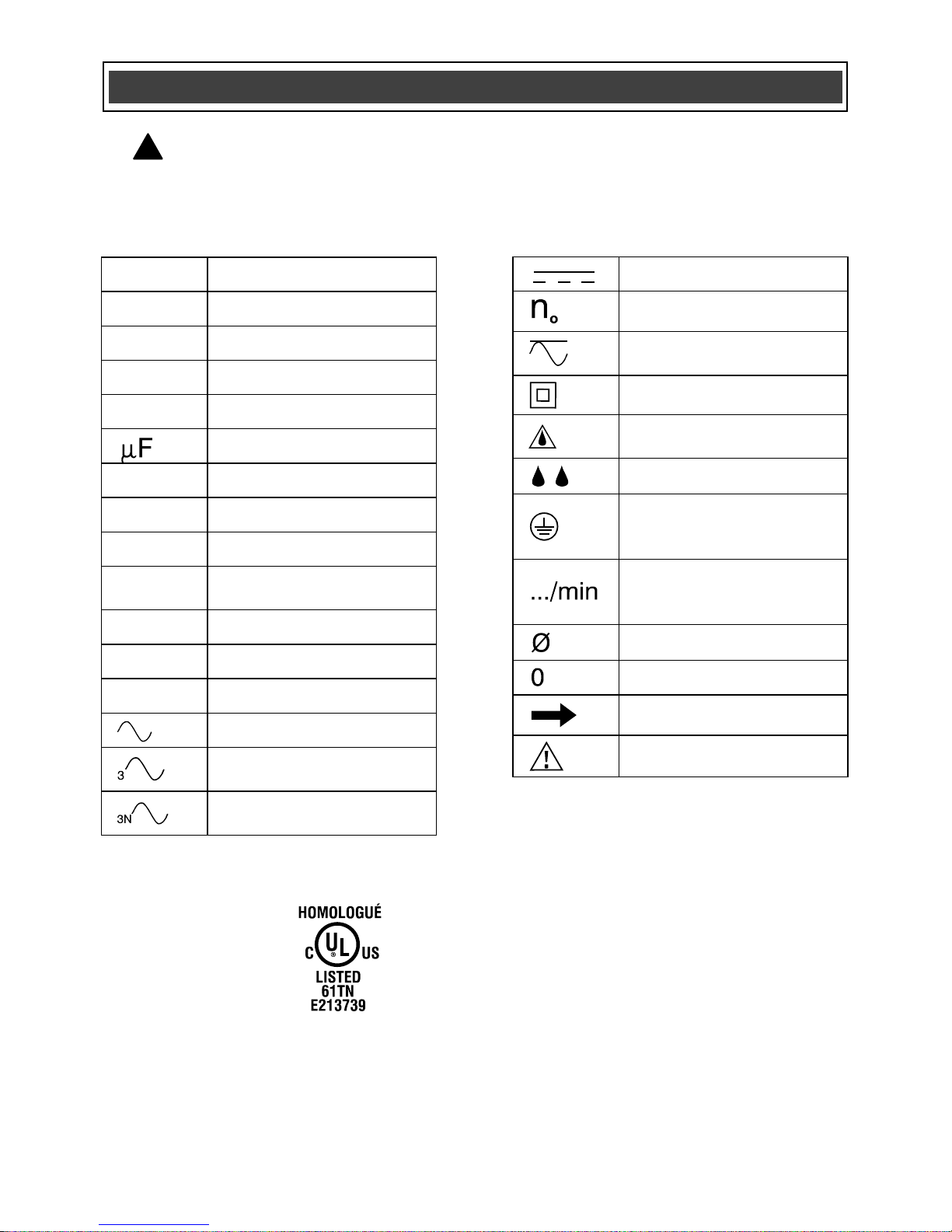
WARNING: Some of the following symbols may appear on the rotary
tool. Study these symbols and learn their meaning. Proper interpretation of
these symbols will allow for more efficient and safer operation of this tool.
!
SYMBOLS
This symbol indicates that this
tool is listed by Underwriters
Laboratories as meeting both
Canadian and U.S.
requirements.
Page 10
10
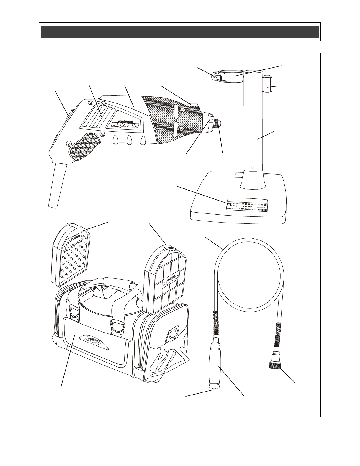
DIAGRAM AND LOCATION OF PARTS
Rotary tool
clamp
Release
lever
Carry bag
Accessory
storage trays
Rotary tool
hanger
Bit storage
Flexible shaft
hanger
Flexible shaft
locking collar
Motor
controls
Rotary
tool
Spindle
lock
Spindle
nut
Collet
nut
Flexible shaft
collet nut
Flexible shaft
mounting nut
Flexible shaft
Cooling
vents
Page 11
11
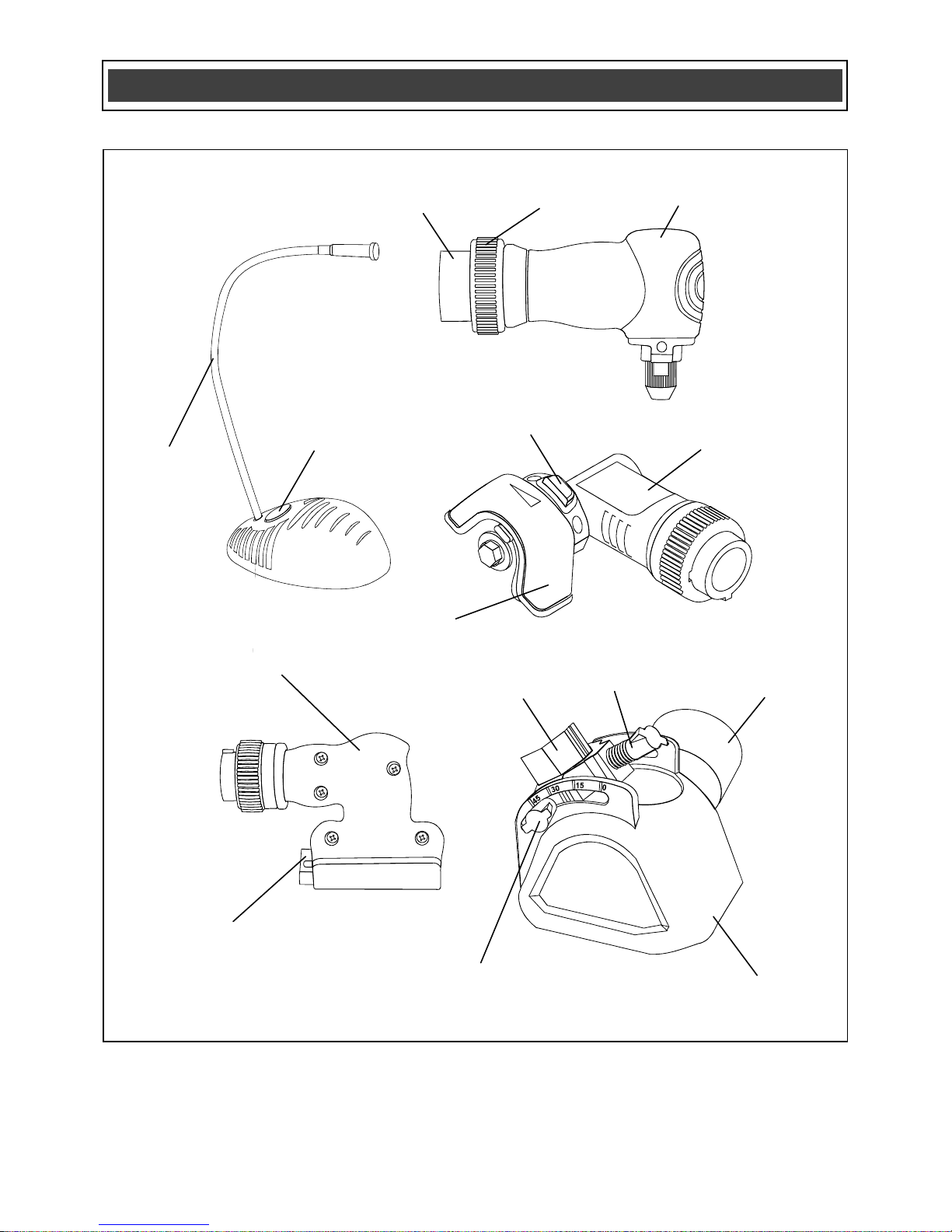
DIAGRAM AND LOCATION OF PARTS
Connecting
adapter
Blade
guard
Mini circular saw
attachment
Right angle
attachment
Vacuum
adaptor
Sanding
attachment
LED
worklight
Connecting
collar
Height
adjusting screw
Rotary tool
connector
Angle adjustment
screw
Angle guide
Clamping
lever
Guard
rotation lock
ON/OFF
button
Page 12

12
AVAILABLE ACCESSORIES
WARNING: Use only accessories
that are recommended for this rotary
tool. Follow the instructions that
accompany the accessories. The use of
improper accessories may result in
injury to the operator or damage to the
rotary tool.
Before using any accessory, carefully read
the instructions or the owner’s manual for
the accessory.
● Grinding stones
● Cut-off wheels
● Polishing wheels
● Wire brushes
● Bristle brushes
● Sanding drums
● Cutting bits
● Drill bits
● Dressing stones
WARNING: If any part is missing or
damaged, do not plug the rotary tool into
the outlet until the missing or damaged
part has been replaced.
CONTENTS
Carefully unpack the rotary tool and all of
its components. Compare the contents
against the following chart entitled “Rotary
Tool Components”.
NOTE: See the illustrations of the rotary
tool and accessories on the following
pages.
WARNING: In order to avoid the risk
of fire or toxic reaction, do not use
gasoline, naphtha, acetone, lacquer
thinner, or similar highly volatile solvents to
clean the rotary tool.
! ! !
ACCESSORIES AND CONTENTS
ROTARY TOOL COMPONENTS
KEY
DESCRIPTION
QTY
A
Rotary cutting tool
1
B
Detail sanding pad
1
C
Contour sanding pads
● Wedge
● Convex
● Concave
1 1 1
D
Batteries for the LED
worklight
2
E
Stand assembly
1
F
LED worklight assembly
1
G
Flexible shaft
1
H
Slide-out storage
containers with
accessories
● See the following
pages for the list of
accessories
2
I
Tote bag
1
J
Angle attachment with
vacuum adaptor
1
K
Circular saw attachment
1
L
Sander attachment
1
M
Right angle attachment
1
Owner’s Manual
(not shown)
1
Page 13

13
CONTENTS
0
A
D
B
C
E
F
G
H
I
J
K
L
M
Page 14

14
Illustration
Item
Description / Size
Qty
Aluminium oxide
grinding stone
Cylinder 3/8" (9 mm)
1
Aluminium oxide
grinding stone
Circular grinding stone
5/8" (16 mm) radial
1
Aluminium oxide
grinding stone
Cylinder with pointed
end 1/4" (6 mm)
1
Aluminium oxide
grinding stone
Parabolic 3/8" (9 mm)
1
Aluminium oxide
grinding stone
Grinding wheel 1"
(25 mm)
1
Aluminium oxide
grinding stone
Cone 5/8" (16 mm)
1
Aluminium oxide
grinding stone
Abrasive wheel 3/4"
(19 mm)
2
Silicon carbide
grinding stone
Cylinder with pointed
end 3/16" (5 mm)
1
Silicon carbide
grinding stone
Cylinder with pointed
end 3/32" (2.5 mm)
1
Silicon carbide
grinding stone
Wheel 3/8" (9 mm)
1
Silicon carbide
grinding stone
Wheel 5/8" (16 mm)
1
Silicon carbide wheel
Abrasive wheel 3/4"
(19 mm)
2
Super duty cut-off
wheel
Fibreglass-reinforced
wheel 1 1/4 " (32 mm)
3
Heavy duty cut-off
wheel
15/16 x .031"
(24 x .8 mm) thick
60
Regular duty cut-off
Wheel
15/16 x .025"
24 x .6 mm) thick
60
Bristle brush
3/4" (19 mm) radial
1
Bristle brush
1/2" (13 mm) axial
1 Stainless steel brush
1/2" axial (13 mm)
1
Stainless steel brush
3/4" (19 mm) radial
1
Brass brush
1/2" (13 mm) axial
1
Felt polishing wheel
1/2" (13 mm)
18
ACCESSORY KIT CONTENTS
Page 15

15
Illustration
Item
Description / Size
Qty
Felt polishing
wheel
1" (25 mm)
1
Felt polishing tip
Pointed tip 3/8"
(9 mm)
1
Cloth wheel
1" (25 mm)
1 Sanding band
60 grit 1/4" (6 mm)
10
Sanding band
120 grit 1/4"
(6 mm)
10
Sanding band
60 grit 1/2"
(13 mm)
10
Sanding band
120 grit 1/2"
(13 mm)
10
Drum sander
1/4"(6 mm) with
1/8" (3 mm) shank
1
Drum sander
1/2" (13 mm) with
1/8" (3 mm) shank
1
Sanding disc
100 grit 3/4"
(19 mm)
80
Sanding disc
220 grit 3/4"
(19 mm)
80
Sanding disc
240 grit 3/4"
(19 mm)
80
Flap wheel
1/4" (6 mm)
1
Diamond wheel
point
Taper point 3/32"
(2.5 mm)
1
Diamond wheel
point
Ball 5/64" (2 mm)
1
Diamond wheel
point
Ball 11/64"
(4.5 mm)
1
Carbide grout
cutter
1/16" (1.5 mm)
1
HSS cutter
Cylinder 1/8"
(3 mm)
1
Collet
1/8" (3 mm)
1 Collet
3/32" (2.5 mm)
1
Collet
1/16" (1.5 mm)
1
ACCESSORY KIT CONTENTS
Page 16

16
Illustration
Item
Description / Size
Qty
Screw mandrel
1/8" (3 mm)
10
Mandrel
For felt wheels
1/8" (3 mm)
10
Wrench
For collet nut and
drum sander
1
Dressing stone
Rectangular 3/8 x
1" (9 x 25 mm)
1
Hook & loop
sandpaper
For detail sander
4
Hook & loop
sandpaper
For contour
sanders
6
Circular saw
blade
48 teeth
2
L-key
For attachments
1
Description
Uses
High-speed steel cutter
Shaping, hollowing, grooving, slotting, and making
tapered holes in soft metals, plastics, and wood.
Carbide grout cutter
Cutting wall and floor grout.
Multi-purpose bit
Cutting wood, plastic, fibreglass, drywall, laminate, and
aluminium and vinyl siding.
Screw mandrel
Holding sanding discs, felt wheels, polishing wheels,
grinding wheels, and cut-off wheels.
Mandrel for emeryimpregnated polishing wheel
Holding the emery-impregnated polishing wheel.
Mandrel for cloth wheel
Holding sanding discs, polishing wheels, grinding
wheels, and cut-off wheels.
Collet
Holding accessories in position.
Collet wrench
Tightening & loosening the collet nut and the screw for
drum sanders.
Dressing stone
Cleaning grinding wheels and stones, and shaping or
reshaping stones for desired applications.
L-key
Locking the flexible shaft in position when loosening or
tightening the collet nut.
Aluminum oxide
Grinding stones
Grinding wheels
Abrasive wheels
Sharpening, de-burring, removing rust , and generalpurpose grinding of most materials, including metals,
castings, welded joints, and rivets.
ACCESSORY KIT CONTENTS
DESCRIPTION AND USE OF ACCESSORIES
Page 17

17
Description
Uses
Silicon carbide
Stones
Wheels
General-purpose grinding of stone, glass, ceramics,
porcelain, and non-ferrous metals.
Cut-off wheel
Cutting, grooving, and trimming all kinds of materials,
including metal, wood, and ceramics; cutting screws
and rusted bolts, making slots in screw heads,
trimming castings, etc.
Polishing wheel
Emery-
impregnated
Cleaning and polishing coarse surfaces.
Polishing wheel
Felt & cloth
Polishing most metal surfaces and plastics. Can be
used with a polishing compound.
Bristle brush
Light de-burring, cleaning, and polishing of silverware,
jewellery, and other precious metals. Can be used with
a polishing compound.
Stainless steel brush
Light de-burring, cleaning, and polishing of corrosionresistant materials like pewter, aluminium, and
stainless steel. Does not cause "after-rust".
Brass brush
Light de-burring, cleaning, and polishing of soft metals
such as gold, copper, brass, etc. Non-sparking, and
does not scratch.
Sanding band
Rough shaping and smoothing of wood and fibreglass,
removing rust from metal surfaces, and shaping rubber
surfaces. Sanding bands are easily replaceable on
drums.
Sanding wheel
Rough shaping and smoothing of wood and fibreglass,
removing rust from metal surfaces, shaping rubber
surfaces, etc.
Flap wheel
Grinding and polishing flat or contoured surfaces.
Finishing surfaces after heavier sanding and material
removal has been completed.
Diamond wheel point
Cutting, sawing, and carving hard materials such as
marble, concrete, brick, porcelain, ceramics, hard
epoxy, and soft and hard wood.
Engraving Cutter
Detailed engraving, carving, and routing in wood,
fibreglass, plastic, and soft metals.
Tungsten-carbide cutter
Shaping, smoothing, and removing material from
hardened steel, stainless steel, cast iron, non-ferrous
metals, fired ceramics, plastics, hard wood, and other
hard materials.
Hook & loop detail sheets
Sanding wood. Used with the detail sander.
Sandpaper for contour sander
Sanding wood. Used with the contour sander.
Circular blade
Cutting wood. Used with the mini circular saw.
DESCRIPTION AND USE OF ACCESSORIES
Page 18

18
CHANGING THE COLLET
Different accessories require the use of
different sized collets. The most common
collet sizes are 1/8, 3/32, and 1/16" (3, 2.5,
and 1.5 mm). It is important to ensure that
the collet size matches the shank of the
accessory.
WARNING: If the collet is too
large for the accessory, the accessory
could be thrown from the tool, which
could cause serious injury.
1. Turn the switch to the OFF position, and
disconnect the plug from the outlet.
2. Depress the spindle lock button (1), and
slowly turn the collet nut (2) until the
spindle lock button locks the spindle in
place (Fig. 1).
3. Hold the spindle lock button down, and
turn the collet nut counter-clockwise using
the collet wrench until it comes free.
4. Remove the collet (3) by pulling it out of
the spindle (4).
5. Insert the replacement collet into the
spindle, and tighten the collet nut by
turning it clockwise while holding the
spindle lock button down.
NOTE: Do not tighten the collet nut without
an accessory installed in the collet. Doing
so will damage the collet.
INSTALLING ACCESSORIES
1. Turn the switch to the OFF position, and
disconnect the plug from the outlet.
!
ASSEMBLY AND OPERATING INSTRUCTIONS
Fig. 1
Page 19

19
INSTALLING ACCESSORIES – cont’d
2. Depress the spindle lock button (1), and
slowly turn the collet nut (2) until the
spindle lock button locks the spindle in
place (Fig. 2).
3. Hold the spindle lock button down, and
turn the collet nut counter-clockwise until
the collet is loose inside the collet nut.
4. Insert the shank of the accessory (3)
into collet.
NOTE: Verify that the proper collet is used
for the accessory. If the collet is too large,
replace it with the next smaller size.
5. Press the spindle lock button, and
engage it in the spindle. While holding the
spindle lock button down, turn the collet
clockwise by hand in order to tighten it .
NOTE: Do not use pliers to tighten the
collet nut. Use the collet wrench that is
provided. Over-tightening the collet will
damage the tool.
6. Pull on the accessory in order to verify
that it is held securely in position.
CONNECTING THE FLEXIBLE SHAFT
TO THE TOOL
WARNING: Do not bend the
flexible shaft to a radius of less than 6”
(15.2 cm) when using it with the rotary
tool. Store the flexible shaft carefully
when it is not in use, avoiding sharp
bends.
!
ASSEMBLY AND OPERATING INSTRUCTIONS
Fig. 2
Page 20

20
CONNECTING THE FLEXIBLE SHAFT TO THE
TOOL – cont’d
1. Remove the collet nut (1) and the
spindle nut (2) from the tool by turning
them counter-clockwise (Fig. 3).
2. Remove the collet from motor shaft (3).
3. Insert the the inner cable of the flexible
shaft (4) into the motor shaft until the
stopper (5) comes into contact with the
motor shaft.
4. Thread the flexible shaft collet nut (6)
onto the motor shaft by turning it
clockwise. Tighten it using the collet
wrench.
5. Thread the flexible shaft nut (7) onto the
tool housing (8) by turning it clockwise.
NOTE: Tighten the flexible shaft nut by
hand only. Do not use pliers or a wrench.
CHANGING THE COLLET AND
ACCESSORIES IN THE FLEXIBLE
SHAFT
In order to change the collet or to install an
accessory in the flexible shaft, follow the
steps listed in the sections entitled
“Changing the collet” and “Installing
accessories”. In order to lock the shaft in
place, pull back on the flexible shaft grip
(1) and rotate the collet until the shaft grip
locks the shaft in place (Fig. 4). The
flexible shaft grip will return to its normal
position when it is not being held in the
locked position.
NOTES:
a) Do not attempt to loosen or tighten the
collet without locking the shaft in place as
described above. Doing so will damage the
flexible shaft.
b) Do not over-tighten the collet nut.
ASSEMBLY AND OPERATING INSTRUCTIONS
Fig. 4
Fig. 3
Page 21

21
ASSEMBLING THE ROTARY TOOL
STAND
The rotary tool stand is used to hold the
rotary tool while using the flexible shaft.
1. Insert the bottom end of the tool holder
(1) into the matching slots (2) in the base
of the stand (3) (Fig. 5).
NOTE: Rotate the tool holder in order to
position the tool clamp (4) toward the front
of the base.
2. Rotate the tool holder 90° clockwise in
order to secure it to the base.
3. Install the flexible shaft on the rotary tool
(Fig. 3).
4. Pull out on the tool holder clamp lever
(5) in order to open the tool holder clamp
(4) (Fig. 6).
5. Insert the flexible shaft (7) through the
tool holder clamp, and insert the rotary tool
(6) into its clamp (4).
NOTE: Verify that the rotary tool is
inserted fully into the clamp.
6. Push the tool holder clamp lever toward
the tool until it snaps into place and holds
the tool securely in place.
7. If the tool is left installed in the stand
with the flexible shaft installed, hang the
collet end of the flexible shaft
in the slotted holder (8) that is located at
the right side of the stand.
8. Accessories can be stored in the base
of the stand, in the spaces that are
provided (9).
ASSEMBLY AND OPERATING INSTRUCTIONS
Fig. 5
Fig. 6
Page 22

22
INSTALLING THE RIGHT ANGLE
ATTACHMENT
1. Remove the collet nut and the collet
from the motor shaft.
NOTE: Engage the spindle lock button in
order to hold the spindle in place while
loosening and tightening the collet nut.
2. Remove the spindle nut (1) from the tool
by turning it counter-clockwise (Fig. 7).
3. Insert the short end of the drive shaft (2)
into the motor shaft (3) until the stopper (4)
comes into contact with the shaft.
4. Slide the collet nut (6) over the drive
shaft (5), and thread it onto the motor shaft
by turning the collet nut clockwise. Tighten
the collet nut using the collet wrench.
5. Remove the right angle attachment
adaptor (7) and the collar (8) from the right
angle attachment (9) by turning the collar
counter-clockwise.
6. Fasten the right angle attachment
adaptor and the collar to the tool (10) by
turning the right angle attachment adaptor
clockwise.
NOTE: Tighten by hand only. Do not use
pliers or a wrench.
7. Insert the end of the drive shaft into the
hole in the right angle attachment (11).
ASSEMBLY AND OPERATING INSTRUCTIONS
Fig. 7
Page 23

23
INSTALLING THE RIGHT ANGLE
ATTACHMENT – cont’d
NOTE: Rotate the right angle attachment
collet nut (12) while pushing the right angle
attachment onto the adaptor until the
square end of the drive shaft is inserted
into the corresponding square in the right
angle attachment.
8. Once the drive shaft is fully engaged
into the right angle attachment, lock the
right angle attachment to the
adaptor by turning the adaptor collar
clockwise.
NOTE: Tighten by hand only. Do not use
pliers or a wrench.
Follow the basic procedures that are
described in the section entitled Changing
the collet and accessories in the flexible
shaft (Fig. 4) in order to change the collet
and accessories in the right angle
attachment. In order to lock the spindle,
rotate the collet nut (12) until the L-key
(13) can be inserted into the hole in the
shaft (14) (Fig. 7A).
INSTALLING THE ANGLE GUIDE AND
THE VACUUM ADAPTER
The angle guide is used to hold the tool at
a specific angle while cutting or grinding.
1. Remove the spindle nut (1) from the tool
by turning it counter-clockwise (Fig. 8).
2. Install the appropriate bit in the rotary
tool (Fig. 2).
3. Install the angle guide (2) onto the tool
by turning the base clockwise onto the
threaded portion of the tool spindle (3).
NOTE: Do not overtighten.
ASSEMBLY AND OPERATING INSTRUCTIONS
Fig. 7A
Fig. 8
Fig. 7
Page 24

24
INSTALLING THE ANGLE GUIDE – cont’d
4. In order to set the cutting angle, loosen
the two angle-adjusting thumb screws (4)
that are located on the sides of the base,
move base to desired angle, and then
retighten the thumb screws.
NOTE: Do not overtighten the thumb
screws.
5. In order to set the cutting depth, loosen
the height-adjusting thumb screw (5), slide
the tool up or down in the base until it is at
the desired cutting depth, and then
retighten the thumb screw.
6. When working with dusty applications,
attach a vacuum to the vacuum adaptor (6)
(Fig 8A). In order to install the vacuum
adaptor, insert the small end of the adaptor
(7) into the vacuum port (8) that is located
on the side of the angle guide.
NOTE: Align the two slots (9) in the
vacuum adaptor with the corresponding
keys (10) in the vacuum port. Turn the
vacuum adaptor clockwise in order to lock
it in position.
INSTALLING THE SANDER
ATTACHMENT
1. Remove the collet nut (1) and the collet
from the motor shaft (2) (Fig. 9).
NOTE: Engage the spindle lock button in
order to hold the spindle in place while
loosening and tightening the collet nut.
2. Remove the spindle nut (3) from the tool
by turning it counter-clockwise.
ASSEMBLY AND OPERATING INSTRUCTIONS
Fig. 8
Fig. 9
Fig. 8A
Page 25

25
INSTALLING THE SANDER ATTACHMENT –
cont’d
3. Insert the short end of the drive shaft (4)
into the motor shaft until the stopper (5)
comes into contact with the shaft.
4. Slide the collet nut over the drive shaft,
and thread it onto the motor shaft by
turning the collet nut clockwise. Tighten
the collet nut using the collet wrench.
5. Remove the sander attachment adaptor
(6) and the collar (7) from the sander
attachment by turning the collar counterclockwise.
6. Fasten the sander attachment adaptor
and the collar to the tool (8) by turning the
sander attachment adaptor clockwise.
NOTE: Tighten by hand only. Do not use
pliers or a wrench.
7. Insert the square end of the drive shaft
(9) into the hole in the sander attachment
(10).
NOTE: Rotate the drive shaft while
pushing the sander attachment onto the
adaptor until the square end of the drive
shaft is inserted into the corresponding
square in the sander attachment.
8. Once the drive shaft is inserted fully into
the sander attachment, secure the sander
attachment to the adaptor by turning the
adaptor collar clockwise onto the sander
attachment threads (11).
NOTE: Tighten by hand only. Do not use
pliers or a wrench.
ASSEMBLY AND OPERATING INSTRUCTIONS
Fig. 9
Page 26

26
INSTALLING SANDPAPER
In order to properly adhere to the
accessories, the sandpaper that is used for
the detail and contour sander accessories
must be of the hook & loop design. The
following instructions describe how to
apply the sandpaper to each type of
sanding accessory.
Detail sander pad
Sandpaper pads are pre-cut to fit the
triangular shape of the detail sander
accessory. In order to apply the
sandpaper, align the pre-cut sandpaper (1)
with the bottom of the detail sander
accessory, and press it firmly onto the
base (2) (Fig. 10).
Contour sanding pads
Sandpaper pads are pre-cut into
rectangular pieces that will fit the shape of
the various contour sander accessories. In
order to apply the sandpaper, align the
pre-cut sandpaper with the “hooked”
bottom and side surfaces of the selected
contour accessory, and press it firmly onto
the hooked surfaces (Fig. 11, 12 & 13).
NOTES:
a) Apply the sandpaper to the accessory
so that it extends to the top of the rubber
pad.
b) If the sheet of sandpaper is too large to
fit the contour accessory properly, trim the
sandpaper to the proper size using an old
pair of scissors.
INSTALLING THE PAD ONTO THE
SANDER
1. Rotate the pad locking lever (1) counterclockwise in order to open the pad clamp
(2) (Fig. 14).
ASSEMBLY AND OPERATING INSTRUCTIONS
Fig. 10
Fig. 11
Fig. 12
Fig. 13
Fig. 14
Page 27

27
INSTALLING THE PAD ONTO THE SANDER –
cont’d
2. Insert the top of the pad and the
sandpaper into the open clamp.
NOTE: Verify that the top of the pad is
centered in the clamp, and that the clamp
grips the sandpaper.
3. Rotate the pad clamp lever clockwise in
order to secure the pad and sandpaper in
position.
SANDING WOOD
WARNING: Wear safety goggles,
hearing protection, and a dust mask
when performing sanding operations.
Failure to use adequate protection may
result in serious injury.
Use the sander in the same manner as
any other finishing sander.
SANDING TIPS
1. Use coarse sandpaper to remove
material from gouges and rough areas
more quickly. Coarse paper lasts longer,
and is less likely to get clogged up with
wood resin and surface finishes.
2. Use fine sandpaper for a smoother
finish.
3. In order to improve sanding action,
verify that the sandpaper is firmly pressed
onto the “hook” area of the sanding pad.
4. Turn rotary tool on before the sandpaper
comes into contact with the workpiece.
!
ASSEMBLY AND OPERATING INSTRUCTIONS
Fig. 14
Page 28

28
SANDING TIPS – cont’d
NOTE: Setting the rotary tool at a faster
speed will produce smoother sanding
action.
5. Keep the rotary tool moving while the
sandpaper is in contact with the workpiece
in order to avoid removing excess material
from the workpiece.
INSTALLING THE MINI CIRCULAR SAW
ATTACHMENT
1. Remove the collet nut (1) and the collet
from the motor shaft (2) (Fig. 15).
NOTE: Engage the spindle lock button in
order to hold the spindle in place while
loosening and tightening the collet nut.
2. Remove the spindle nut (3) from the tool
by turning it counter-clockwise.
3. Insert the short end of the drive shaft (4)
into the motor shaft until the stopper (5)
comes into contact with the shaft.
4. Slide the collet nut over the drive shaft
(9), and thread it onto the motor shaft by
turning the collet nut clockwise. Tighten
the collet nut using the collet wrench.
5. Remove the saw attachment adaptor (6)
and the collar (7) from the circular saw
attachment by turning the collar counterclockwise.
ASSEMBLY AND OPERATING INSTRUCTIONS
Fig. 15
Page 29

29
INSTALLING THE MINI CIRCULAR SAW
ATTACHMENT – cont’d
6. Fasten the saw attachment adaptor and
the collar to the tool (8) by turning the saw
attachment adaptor clockwise.
NOTE: Tighten by hand only. Do not use
pliers or a wrench.
7. Insert the square end of the drive shaft
(9) into the hole in the saw attachment
(10).
NOTE: Rotate the saw blade screw (11)
while pushing the saw attachment onto the
adaptor until the square end of the drive
shaft is inserted into the corresponding
square in the saw attachment.
8. Position the saw blade to the LEFT side
of the rotary tool. The hexagonal
positioning locks will engage when the
body of the saw attachment is in the
proper position.
9. Once the drive shaft and positioning
locks are fully engaged, secure the saw
attachment to the adaptor by turning the
adaptor collar clockwise.
NOTE: Tighten by hand only. Do not use
pliers or a wrench. Loosen adaptor collar
when removing the circular saw
attachment from the rotary tool.
10. Rotate the saw guard assembly until
the bottom sliding surface of the guard
assembly and the rotary tool are in the
desired position. In order to rotate the
guard assembly, press the release button
(12) and rotate the guard assembly until
the release button snaps into the next
locked position.
ASSEMBLY AND OPERATING INSTRUCTIONS
Fig. 15
Page 30

30
INSTALLING A SAW BLADE
1. Lock the saw attachment shaft in place.
in order to lock the shaft in place, rotate
the screw that holds the blade onto the
shaft until the hole in the shaft is aligned
with the hole in the saw attachment body
(1) (Fig. 16). Insert the L-Key (2) through
the holes in order to lock the shaft in place.
NOTE: Do not attempt to loosen or tighten
the blade screw without locking the shaft
as described above. Doing so will damage
the flexible shaft.
2. Remove the saw blade screw (1), the
locking washer (2), and the large washer
(3) by turning the screw clockwise using a
5/16" (8 mm) wrench (Fig. 16A). The screw
has a left-hand thread.
3. Rotate the blade guard lever (4)
forward.
4. Place the saw blade onto the spindle
(5).
NOTE: Verify that the teeth on the bottom
of the saw blade are pointing forward.
5. Secure the saw blade in position by
replacing the large washer, the locking
washer, and the saw blade screw in the
proper order.
NOTES:
a) Place the hollow side of the large
washer against saw blade.
b) Lock the saw blade shaft using the
L-Key.
c) Tighten the saw blade screw by turning
it counter-clockwise. The screw has a lefthand thread.
d) Do not overtighten the saw blade screw.
Doing so will damage the threaded
spindle.
ASSEMBLY AND OPERATING INSTRUCTIONS
Fig. 16A
Fig. 16
Page 31

31
CUTTING WOOD
WARNING: Wear safety goggles,
hearing protection, and a dust mask when
performing sawing operations. Failure to
use adequate protection could result in
serious injury.
WARNING: Do not place hands
near or below the cutting line.
The mini circular saw attachment is
designed to make smooth cuts in
extremely thin pieces of wood. Verify that
the saw blade is not in contact with
anything, and that the operator's hands are
clear of the blade before turning the rotary
tool on.
1. Turn rotary tool on.
2. Set the speed to 25,000 RPM.
3. Position the saw attachment on the
edge of the workpiece, with the blade
aligned with the cutting line.
4. Slowly move the blade toward the
cutting line until it comes into contact with
the workpiece.
5. Once the blade begins to cut, move the
blade into the workpiece at a slow and
steady pace, following the cutting line.
NOTE: The mini circular saw attachment is
designed to cut straight lines only. It is not
designed to cut curves.
Moving the saw at a slow and steady pace
will produce a smooth cut. Forcing the
blade to cut too quickly will cause it to
overheat, which will result in burn marks
on the wood, a rough cut, and a dull blade.
!
!
ASSEMBLY AND OPERATING INSTRUCTIONS
Page 32

32
CUTTING WOOD – cont’d
WARNING: Once the cutting
operation is complete, verify that the saw
blade has come to a complete stop before
setting the rotary tool down.
WARNING: Do not touch the blade
immediately after cutting, because it will be
hot enough to cause burns.
ASSEMBLING THE LED WORKLIGHT
This rotary tool is equipped with a freestanding LED worklight that can be placed
on any flat surface near the workpiece.
The flexible arm can be bent in order to
focus the light on the desired location.
Install the batteries into the base of the
LED worklight as follows:
1. Turn the worklight upside down.
2. Remove the battery cover (1) from the
base of the worklight (2) by lifting the side
where the slot (3) is located (Fig. 17).
3. Install two AAA alkaline batteries (4) into
the battery compartment.
NOTE: Position the batteries with the
positive (+) end of each battery as
illustrated in the picture that is in the
battery compartment.
4. Re-install the cover of the battery
compartment.
5. Turn the LED worklight on or off using
the ON/OFF button (5) that is located on
the top of the base (Fig. 17A). Push the
button once in order to turn the light on.
Push it again to turn the light off.
!
!
ASSEMBLY AND OPERATING INSTRUCTIONS
Fig. 17
Fig. 17A
Page 33

33
SELECTING THE PROPER SPEED
The different types of operations that can
be performed require that the rotary tool be
used at different speeds. The following
chart outlines some of the basic speed
settings:
OPERATION
SPEED
(RPM)
Sanding
13,000
Cutting metal
35,000
Sanding wood
13,000
Cutting hard metal
29,000
Engraving metal
27,000
Sawing
25,000
De-burring
19,000
Drilling holes
17,000
Removing rust
13,000
Sharpening
9,000
Polishing
9,000
WARNING: For safety reasons, the operator must read the sections of this
Owner's Manual entitled “GENERAL SAFETY WARNINGS”, “POWER TOOL
SAFETY”, “SPECIFIC SAFETY RULES”, EXTENSION CORD SAFETY” and
“SYMBOLS” before using this rotary tool.
Verify the following every time the rotary tool is used:
1. All accessories that are being used are in good condition and are not
damaged in any way.
2. The workpiece is properly secured and the accessory is securely installed.
3. The operator is wearing safety glasses.
Failure to observe these safety rules will significantly increase the risk of injury.
!
ASSEMBLY AND OPERATING INSTRUCTIONS
Page 34

34
DIGITAL MOTOR CONTROL
This rotary tool features advanced digital
controls, including an LCD (liquid crystal
display) speed indicator and a speed
memory function. The following sections
describe how these functions work.
ON/OFF SWITCH
WARNING: Verify that the bit is
securely installed in the collet and that the
cutting accessory is not in contact with
anything before turning the switch to the
“ON” position.
1. Push the left side of the switch in order
to turn it to the "ON" position (1) (Fig. 18).
NOTE: The tool will start, and the digital
display (2) will indicate the speed that was
previously set. The indicated speed will be
between “05” and “35” (5,000 and 35,000
RPM).
2. Push the right side of the switch in order
to turn it to the "OFF" position (3) (Fig. 19).
NOTE: The digital display will go blank.
ADJUSTING THE SPEED
The speed of the tool can be adjusted from
5,000 RPM to 35,000 RPM in order to
accommodate the various types of
operations.
NOTE: The motor is equipped with a soft
start feature. When the switch is turned to
the "ON" position, the motor will start
slowly, and will increase in speed until the
preset speed is attained.
ASSEMBLY AND OPERATING INSTRUCTIONS
Fig. 18
Fig. 19
!
Page 35

35
ADJUSTING THE SPEED – cont’d
1. Turn the switch to the "ON" position.
The rotary tool will start slowly, and will
increase in speed until the preset speed is
attained. The display will read between
“05” and “35” (5,000 and 35,000 RPM).
2. In order to increase the speed of the
tool, press the “+” speed control button (4)
once (Fig. 20). The speed of the tool will
increase by “02” (2,000 RPM).
3. Continue to increase the speed of the
tool by pressing the “+” speed control
button several times (Fig. 21). The speed
of the tool will increase by “02” (2,000
RPM) each time the “+” speed control
button is pressed, until it reaches the
maximum speed of “35” (35,000 RPM).
4. In order to decrease the speed of the
tool, press the “–” speed control button (5).
NOTE: Each time the “–“ speed control
button is pressed, the speed of the tool will
decrease by “02” (2,000 RPM).
SPEED MEMORY
The digital controls of this rotary tool
include a “memory” function. When the tool
is turned on, the tool will automatically start
at the speed that was set the last time the
tool was turned off. This function is
particularly useful when the tool is turned
off in order to change cutting bits.
Adjust the speed to the desired setting
each time the tool is turned on.
ASSEMBLY AND OPERATING INSTRUCTIONS
Fig. 20
Fig. 21
Page 36

36
WARNING: When servicing, use
only identical replacement parts. The use
of any other part may create a hazard or
damage the rotary tool.
Do not abuse power tools. Abusive
practices can damage the tool and the
workpiece.
WARNING: Do not attempt to
modify this rotary tool or to create
accessories. Any such alteration or
modification is considered to be misuse,
and could result in a hazardous condition
that may lead to serious injury. Doing so
will also void the warranty.
CLEANING
Do not use solvents to clean plastic parts.
Many plastics are susceptible to damage
from various types of commercial solvents.
Use a clean cloth to remove dirt, dust, oil,
grease, etc.
WARNING: Do not allow brake
fluids, gasoline, petroleum-based products,
penetrating oils, etc. to come into contact
with plastic parts. These substances
contain chemicals that can damage,
weaken, or destroy plastic.
Power tools are subjected to accelerated
wear and possible premature failure when
they are used on fiberglass boats and
sports cars, wallboard, spackling
compounds, or plaster. The chips and
grindings from these materials are
extremely abrasive to some parts of power
tools, including bearings, brushes,
commutators, etc. Therefore, it is
recommended that this tool not be used for
extended work on any fiberglass material,
wallboard, spackling compound, or plaster.
If this rotary tool is used on these
materials for an extended period, it must
be cleaned frequently by blowing it out with
an air jet.
WARNING: Wear safety goggles or
safety glasses that have side shields
whenever performing any operation
with a rotary tool. It is also critical to wear
safety goggles or safety glasses that have
side shields, as well as a dust mask, when
blowing dust out of the tool using an air jet.
Failure to observe these safety
precautions could result in permanent eye
or lung damage.
LUBRICATION
All of the bearings in this rotary tool have
been lubricated with a sufficient quantity of
high-grade lubricant for the life of the tool
under normal conditions. No further
lubrication is required.
!
!
MAINTENANCE
! ! !
Page 37

37
EXPLODED VIEW
Page 38

38
WARNING: When servicing, use only Mastercraft® replacement parts. The use of
any other parts may create a safety hazard or cause damage to the rotary tool.
Any attempt to repair or replace electrical parts on this rotary tool may create a safety
hazard unless repairs are performed by a qualified technician. For more information, call
the Toll-Free Helpline, at 1-800-689-9928.
Always order by PART NUMBER, not by key number.
Key #
Part #
Part Name
Quantity
1
313300
Accessory collar
1 2 215100
Collet nut
1 3 216506
1/8" collet
1
4
213016
Output shaft
1
5
520008
Bearing 626RS
2 6 314009
Fan 1 7
134008
Armature
1 8 138008
Stator
1
9
321006
Bearing sleeve
1
10
500843
Screw M3 x 10
2
11
504000
Spring washer 3
2
12
503008
Small washer 3
2
13
215014
Locking pin
1
14
221286
Washer
1
15
240824
Locking pin spring
1
16
312934
Spindle lock button
1
17
300076
Housing (right)
1
18
234033
Aluminium cover (right)
1
19
500001
Tapping screw ST2.9 x 16
6
20
162853
Rectifying PCB
1
21
500409
Tapping screw ST2.2 x 16
3
22
162852
V.S. PCB
1
23
242553
Hanging loop
1
24
312098
Back cover
1
25
317013
"-" speed control button
1
26
317012
"+" speed control button
1
27
500006
Tapping screw ST2.9 x 12
2
28
224455
Cord clamp
1
29
322006
Cord guard
1
30
160205
Cord set
1
31
314527
Brush holder support
2
32
222827
Brush holder
2
33
342027
Carbon brush
2
34
300076
Housing (left)
1
35
234033
Aluminium cover (left)
1
!
PARTS LIST
Page 39

39
Rev 1.3 13/07/2008
WARRANTY
*Limited 5-year Replacement Warranty
This Mastercraft Maximum product carries a five (5) year replacement
warranty against defects in workmanship and materials. Mastercraft
Canada agrees to replace the defective product free of charge with
the same model or one of equal value or specification, within the
stated warranty period, when returned by the original purchaser with
proof of purchase. The case carries a two (2) year replacement
warranty against defects in workmanship and materials. This product
is not guaranteed against wear or breakage due to misuse and/or
abuse.
This product is not guaranteed if used for industrial or
commercial purposes.
 Loading...