

Page 1
3 A Electric Pneumatic-action Multi-nailer
54-2963-8
Instruction Manual
PRODUCT SPECIFICATIONS
Motor:
120 V AC, 60 Hz, 3.0 A
Motor speed:
0–28,000 RPM (no load)
Hammer speed:
0–4200 BPM
Nail length:
1 5/8–6" (4–15 cm)
Nail type:
Round, serrated and oval shank
Nail head:
3/8" (10 mm) Maximum
Nail head position:
1 mm counter sunk to 10 mm proud
Weight:
5 lb 12 oz (2.6 kg)
TOLL-FREE HELPLINE 1-800-689-9928
Imported by Mastercraft Canada Toronto, Canada M4S 2B8
Page 2

2
Product specifications ………….…………………………………………………….
1
Table of contents ……………………………………………………………………...
2
General safety warnings ……………………………………………………………..
3– 4
Eye, ear & lung protection ……………………………………………………………
3–4
Electrical safety ……………………………………………………………………….
4
Power tool safety ……………………………………………………………………...
5–6
General safety rules …………………………………………………………………..
5
Work area ………………………………………………………………….…………..
5
Electrical safety ……………………………………………………………………….
5
Personal safety ………………………………………………………………………..
5–6
Use and care of power tools .………………………………………………………..
6
Service …………………………………………………………………………………
6
Specific safety rules …………………………………………………………………..
7
Extension cord safety ………………………………………………………………...
8
Symbols ………………………………………………………………………………..
9
Know your multi-nailer ……………………………………………………………….
10
Accessories ……………………………………………………………………………
10
Contents ……………………………………………………………………………….
10–11
Assembly and operation ……………………………………………………………..
12–16
Lock-off switch ………………………………………………………………………...
12
Adjusting depth of drive ………………………………………………………………
12
Installing no-mar tip …………………………………………………………………..
13
Left/right holster pouch ……………………………………………………………….
14
Loading nail ……………………………………………………………………………
14
Driving a nail …………………………………………………………………………..
15–16
Maintenance …………………………………………………………………………..
17
Exploded view …………………………………………………………………………
18
Parts list ………………………………………………………………………………..
19–20
Warranty ……………………………………………………………………….………
21
TABLE OF CONTENTS
Page 3

3
EYE, EAR & LUNG PROTECTION
This instruction manual includes the following:
• General Safety Rules
• Specific Safety Rules and Symbols
• Functional Description
• Assembly
• Operation
• Maintenance
• Accessories
!
ALWAYS WEAR EYE PROTECTION THAT CONFORMS WITH CSA
REQUIREMENTS or ANSI SAFETY STANDARD Z87.1
FLYING DEBRIS can cause permanent eye damage. Prescription
eyeglasses ARE NOT a replacement for proper eye protection.
WARNING: Non-compliant eyewear can cause serious injury if
broken during operation of a power tool.
SAVE THESE INSTRUCTIONS FOR REFERENCE
WARNING: Use hearing protection, particularly during extended
periods of operation of the tool or if the operation is noisy.
!
GENERAL SAFETY WARNINGS
CAUTION: Before using this tool or any of its accessories, read this
manual and follow all Safety Rules and Operating Instructions.
!
Page 4
4
ELECTRICAL SAFETY
WARNING: To avoid electrical hazards, fire hazards or damage to the
tool, use proper circuit protection.
This tool is wired at the factory for 110–120 V operation. It must be
connected to a 110–120 V, 15 A time-delayed fuse or circuit breaker. To
avoid shock or fire, replace power cord immediately if it is worn, cut or
damaged in any way.
GENERAL SAFETY WARNINGS
WEAR A DUST MASK THAT IS DESIGNED TO BE USED WHEN
OPERATING A POWER TOOL IN A DUSTY ENVIRONMENT.
WARNING: Dust that is created by power sanding, sawing, grinding,
drilling, and other construction activities may contain chemicals that are
known to cause cancer, birth defects or other genetic abnormalities. These
chemicals include:
• Lead from lead-based paints
• Crystalline silica from bricks, cement, and other masonry products
• Arsenic and chromium from chemically-treated lumber
The level of risk from exposure to these chemicals varies according to how
often this type of work is performed. In order to reduce exposure to these
chemicals, work in a well-ventilated area, and use approved safety
equipment, such as a dust mask that is specifically designed to filter out
microscopic particles.
!
Page 5

5
GENERAL SAFETY RULES
WARNING: Read and understand
all instructions. Failure to follow all
instructions listed below may result in
electric shock, fire and/or serious personal
injury.
WORK AREA
Keep your work area clean and well lit.
Cluttered benches and dark areas invite
accidents.
Do not operate power tools in potentially
explosive environments, such as in the
presence of flammable liquids, gas or dust.
Power tools create sparks that may ignite
the dust or fumes.
Keep bystanders, children and visitors
away while operating the tool. Distractions
can cause the operator to lose control.
ELECTRICAL SAFETY
Double insulated tools are equipped with a
polarized plug (one blade is wider than the
other). This plug will only fit into a
polarized plug one way.
If the plug does not fit into the outlet
properly, reverse the plug. If it still does not
fit, contact a qualified electrician to install a
polarized outlet. Do not alter the plug in
any way. Double insulation eliminates the
need for the three-prong grounded power
cord and grounded power supply system.
Avoid contact between the operator's body
and grounded surfaces such as pipes,
radiators, ranges, and refrigerators. There
is an increased risk of electric shock if the
operator's body is grounded.
Do not expose power tools to rain or wet
conditions. Water entering the power tool
will increase the risk of electric shock.
Do not abuse the cord. Do not use the
power cord to carry the tool or to pull the
plug out of the outlet. Keep the power cord
away from heat, oil, sharp edges, and
moving parts. Replace a damaged power
cord immediately. A damaged power cord
increases the risk of electric shock.
When operating a power tool outdoors,
use an outdoor rated extension cord type
“W-A” or “W”. These cords are rated for
outdoor use and they reduce the risk of
electric shock.
PERSONAL SAFETY
Stay alert, be aware of the surroundings,
and use common sense when operating a
power tool. Do not use a power tool while
tired or under the influence of drugs,
alcohol, or medication. A moment of
inattention while operating a power tool
could result in serious personal injury.
Dress properly. Do not wear loose clothing
or jewellery.
Contain long hair. Keep hair, clothing, and
gloves away from moving parts. Loose
clothing, jewellery, or long hair can get
caught in moving parts.
!
POWER TOOL SAFETY
Page 6

6
PERSONAL SAFETY – continued
Avoid accidental start-ups. Verify that the
switch is in the OFF position before
plugging the tool in. Carrying a power tool
with a finger on the switch or plugging in a
tool that has the switch in the ON position
invites accidents.
Remove adjusting keys and wrenches
before turning the tool ON. A wrench or
key that is left attached to a rotating part of
the tool may result in personal injury.
Do not overreach. Keep proper footing and
balance at all times. Proper footing and
balance allows the operator to maintain
better control of the tool in unexpected
situations.
Use safety equipment. Always wear eye
protection.
Use a dust mask, non-skid safety shoes, a
hardhat, or hearing protection when
appropriate.
USE AND CARE OF POWER TOOLS
Use clamps or another practical means to
secure and support the workpiece to a
stable platform. Holding the workpiece in a
hand or against the body is not stable, and
may lead to loss of control.
Do not force the tool. Use the correct tool
for the application. The correct tool will do
the job better and safer when it is used at
the rate that it was designed to work at.
Do not use a power tool if it cannot be
turned ON or OFF using the power switch.
A tool that cannot be controlled using the
switch is dangerous, and must be repaired.
Disconnect the plug from the outlet before
making any adjustments, changing
accessories, or storing the tool. Such
preventive safety measures reduce the risk
of accidental start-ups.
When power tools are not in use, store
them out of the reach of children or
untrained persons. Tools are dangerous in
the hands of untrained users.
Maintain tools with care. Keep cutting tools
sharp and clean. Properly maintained
cutting tools with sharp cutting edges are
less likely to bind, and are easier to
control.
Inspect the tool for misalignment or binding
of moving parts, broken parts, and any
other condition that may affect the
operation of the tool. If it is damaged, have
the tool serviced before using it. Many
accidents are caused by poorly maintained
tools.
Use only accessories that are
recommended by the manufacturer for this
model. Accessories that are suitable for
one tool may become hazardous when
used with another tool.
SERVICE
Tools must be serviced by qualified
personnel. Service or maintenance
performed by non-qualified personnel
could result in a risk of injury.
When servicing a tool, use only identical
replacement parts. Follow the instructions
in the Maintenance section of this Manual.
The use of unauthorized parts, or failure to
follow the instructions in the Maintenance
section of this Manual may create a risk of
electric shock or injury.
POWER TOOL SAFETY
Page 7
7
WARNING: Know your
multi-nailer. Read the Owner’s Manual
carefully. Learn the tool’s applications
and limitations, as well as the specific
potential hazards related to this tool.
Following this rule will reduce the risk of
electric shock, fire or serious injury.
Always wear eye protection. Any power
tool can throw foreign objects
into your eyes and cause
permanent eye damage.
ALWAYS wear safety goggles
(not glasses) that comply with ANSI safety
standard Z87.1. Everyday glasses have
only impact-resistant lenses. They ARE
NOT safety glasses.
WARNING: Glasses or goggles
not in compliance with ANSI Z87.1
could cause serious injury when they
break.
Always use hearing protection when
operating the multi-nailer.
Use only the types of nails recommended
in this instruction manual. Use of nails or
accessories not recommended for this tool
may result in personal injury and damage
to the tool.
Do not touch the metal parts of the tool
during operation. Hold the tool only by the
insulated handle and insulated housing.
Inadvertently driving a nail into a “live”
electrical wire could shock the operator if
you are touching the metal housing.
Do not activate the trigger switch unless
the nail is in contact with the workpiece.
Serious injury may result from a flying nail.
Never use this tool for any purpose other
than recommended in this instruction
manual. Never attempt to drive nails into
extremely hard materials such as concrete
or rock. Personal injury or damage to the
tool may result.
When wearing gloves, make sure they fit
tightly and provide a non-slip grip. Leather
gloves offer the best protection.
Always use two hands when operating the
multi-nailer. Use one hand on the insulated
handle and the other on the insulated
lower housing of the tool body.
Use caution when nailing thin materials.
Nails may penetrate through the material
and injure anyone behind the workpiece or
in the immediate area.
Always remove the plug from the power
source before servicing or removing a
jammed nail.
Do not allow the tool to become
overheated. During normal operation, the
tool may feel warm to the touch. If the
nailer starts to feel hot, discontinue use
until the nailer cools down.
Keep the multi-nailer handle and body
clean and free of oil and grease. Always
use a clean dry cloth when cleaning. Do
not use solvents, brake fluid, gasoline or
other petroleum products to clean the tool.
They will damage the tool.
SPECIFIC SAFETY RULES
!
!
Page 8

8
WARNING: Keep the extension
cord clear of the work area. Position the
cord so that it will not get caught on the
workpiece, a tool, or any other obstruction
while the power tool is in use.
If an extension cord is used with this multinailer, verify that it is in good condition.
When using an extension cord, be sure to
use one that is heavy enough to carry the
current that the tool will draw. An
undersized cord will cause a drop in line
voltage, which will result in a loss of power
and cause overheating of the tool.
The following table shows the correct size
to use according to cord length and the
amperage rating that is listed on the tool's
nameplate. When in doubt, use the next
heavier gauge. The smaller the gauge
number, the heavier the cord.
Verify that the extension cord is properly
wired and in good condition. Replace a
damaged extension cord immediately, or
have it repaired by a qualified electrician
before using it. Keep the extension cord
away from sharp objects, excessive heat,
and damp or wet areas.
Use a separate electrical circuit for power
tools. This circuit must consist of not less
than 14-gauge wire, and should be
protected by either a 15 A time-delayed
fuse or a circuit breaker. Before connecting
the power tool to the outlet, verify that the
switch is in the OFF position, and that the
voltage of the power source is the same as
the voltage that is indicated on the tool's
nameplate. Running this multi-nailer at a
lower voltage will damage the motor.
EXTENSION CORD SAFETY
MINIMUM GAUGE (AWG) EXTENSION
CORDS
(120 V use only)
Ampere Rating
Total length in feet
More
Than
Not
More
Than
25’ 50’ 100’ 150’ 0 6
18
16
16
14 6 10
18
16
14
12
10
12
16
16
14
12
12
16
14
12
Not Applicable
!
Page 9

9
V
Volts
A
Amperes
Hz
Hertz
W
Watts
kW
Kilowatts
Microfarads
L
Litres
kg
Kilograms
H
Hours
N/cm2
Newtons per square
centimetre
Pa
Pascals
Min
Minutes
S
Seconds
Alternating current
Three-phase alternating
current
Three-phase alternating
current with neutral
Direct current
No load speed
Alternating or direct
current
Class II construction
Splash-proof
construction
Watertight construction
Protective grounding at
grounding terminal,
Class I tools
Revolutions or
reciprocations per
minute
Diameter
Off position
Arrow
Warning symbol
SYMBOLS
WARNING: Some of the following symbols may appear on the multi-
nailer. Study these symbols and learn their meaning. Proper interpretation of
these symbols will allow for more efficient and safer operation of this tool.
!
This symbol designates that
this tool is listed with
Canadian requirements by
ETL Testing Laboratories, Inc.
3042597
HOMOLOGUÉ
Page 10

10
AVAILABLE ACCESSORIES
WARNING: Use only nails that are
recommended for this multi-nailer.
Follow the instructions that accompany
the accessories. The use of improper
accessories may result in injury to the
operator or damage to the multi-nailer.
● Nails
WARNING: If any part is missing or
damaged, do not plug the multi-nailer into
the power source until the missing or
damaged part is replaced.
CONTENTS
Carefully unpack the multi-nailer. Compare
against the “MULTI-NAILER
COMPONENTS” chart below.
NOTE: See illustration of multi-nailer at
right.
WARNING: To avoid fire or toxic
reaction, never use gasoline, naphtha,
acetone, lacquer thinner or similar highly
volatile solvents to clean the tool.
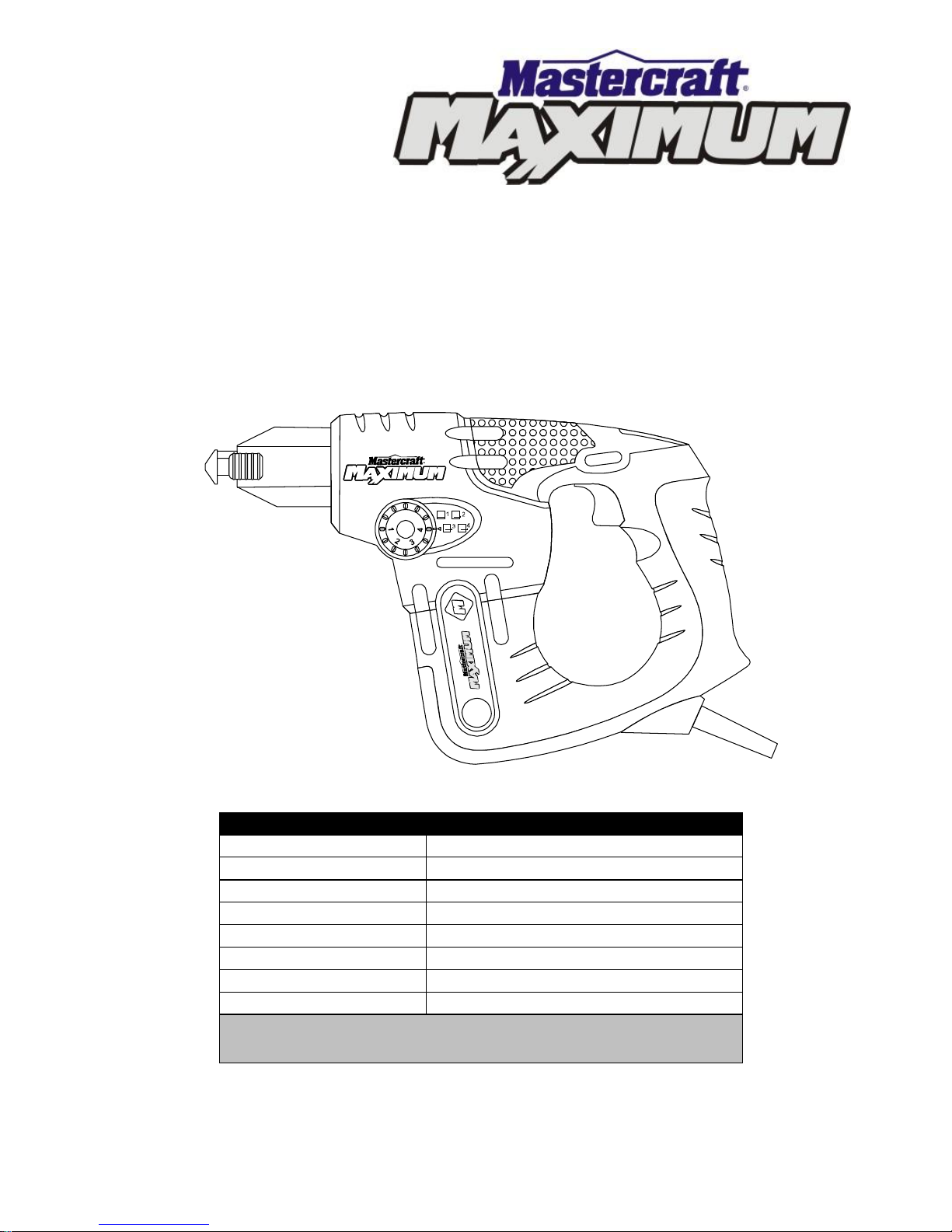
KNOW YOUR MULTI-NAILER
ACCESSORIES & CONTENTS
! ! !
MULTI-NAILER COMPONENTS
KEY
DESCRIPTION
QTY
A
Electric Pneumaticaction Multi-nailer
1
B
Left/right holster pouch
1
C
No-mar tip
1
Owner’s manual
1
Variable speed
trigger switch
Nail gripping
jaws
Jaw release
button
Insulated
handle
Lock-off
switch
Depth
adjustment knob
Insulated
housing
Page 11

11
CONTENTS
Page 12

12
LOCK-OFF SWITCH
This tool is equipped with a lock-off switch
that will prevent inadvertent operation of
the tool. Place the lock-off switch (1) in the
middle position to activate (Fig. 1) the lockoff feature. The lock-off switch should
always be used during the following
situations:
● Removing a bent or jammed nail
● When tool is left unattended
ADJUSTING DEPTH-OF-DRIVE
The 4-stage depth-of-drive dial allows the
user to easily select the desired nail drive
depth (Fig. 2).
NOTE: The depth to which the nail is
driven will depend upon two factors:
a) The longer the nailer is allowed to
hammer, the deeper the nail will be
driven.
b) With the no-mar tip installed, the nail
depth will be reduced.
Depth Setting Ranges
Position
Depth range
1
Nail head counter sunk by 1 mm
to raised 1 mm.
2
Nail head flush with the surface
to raised 2 mm.
3
Nail head raised 3–5 mm above
surface.
Suitable for hanging heavy
objects.
4
Nail head raised 8–10 mm above
surface.
Suitable for hanging lighter
objects.
To set the nail depth, press dial inward (1)
and rotate it to the desired position (Fig. 3).
ASSEMBLY AND OPERATION
Fig. 1
Fig. 3
Fig. 2
Page 13

13
INSTALLING NO-MAR TIP
When driving nails into soft materials, the
nail gripping jaws may mar the workpiece.
To protect the soft material you should
install the no-mar tip.
To install the no-mar tip, slide the no-mar
tip (1) over the nail gripping jaws (2) and
over the rear of the nail gripping jaws (3)
(Fig. 4).
NOTES:
a) Make sure the rectangular openings
(4) on both sides of the no-mar tip are
fully engaged with the matching
rectangular rear portions (3) of the nail
gripping jaws (Fig. 5). This will ensure
the no-mar tip is installed correctly and
will be held in place during operation
of the tool.
b) When the no-mar tip is installed, the
nailer will drive the head of the nail
approximately 2 mm less distance
than when the no-mar tip is NOT
installed.
To remove the no-mar tip, carefully pull
outwards on the sides of the no-mar tip
and slide it off the nail gripping jaws.
ASSEMBLY AND OPERATION
Fig. 4
Fig. 5
Page 14

14
LEFT/RIGHT HOLSTER POUCH
This multi-nailer is equipped with a holster
pouch that allows the user to conveniently
keep the tool and nails close at hand.
1. Slide the end of a large work belt (1)
through the holster pouch belt loop (2)
(Fig. 6).
2. Fasten the belt around your waist.
3. Position the holster on your hip for
convenient access to nails and the
tool.
LOADING A NAIL
You can load any of the following types of
nails into the multi-nailer:
Length
1 5/8–6" (4–15 cm)
Shank
Round, serrated, spiral or oval
Head
10 mm (Maximum)
1. Using your thumb, press the jaw
release button (1) (Fig. 7).
2. Position the nail (2) between the jaws
(3) and insert it into the opening until
the head of the nail makes contact
with the anvil, as shown in Fig. 8.
3. Remove your thumb from the jaw
release button to de-activate the jaws.
NOTE: The jaws will clamp onto the nail
head. If the nail is not tightly secured and
straight, press the jaw release button and
make sure the nail is properly aligned in
the jaws.
Fig. 8
ASSEMBLY AND OPERATION
1
2
Fig 6
Fig. 7
Page 15

15
DRIVING A NAIL
Always drive a test nail in a scrap
workpiece of the same type as the good
workpiece. This action will verify the depth
setting and the most effective speed to
drive the nail.
While driving a test nail, experiment with
the speed. Generally, you will use lower
speeds to start nailing and for driving
larger nails into hardwoods.
For safety reasons, the operator
must read the sections of this
Owner’s Manual entitled “GENERAL
SAFETY WARNINGS”, “POWER
TOOL SAFETY”, “SPECIFIC SAFETY
RULES”, EXTENSION CORD
SAFETY” and “SYMBOLS” before
using this multi-nailer.
Verify the following every time the
multi-nailer is used:
1. Safety glasses and hearing
protection are being worn.
2. Area where nails are being
driven is free of any possibility
of “live” electrical wires.
3. Appropriate nails are being
used.
Failure to observe these safety rules
will significantly increase the risk of
injury.
WARNING
!
ASSEMBLY AND OPERATION
Page 16

16
DRIVING A NAIL – continued
NOTE: Do not use the lower speeds for
long periods of time. Lower speeds tend to
cause the multi-nailer to overheat and
shorten the life of the trigger switch.
1. Hold the multi-nailer in a position so
that the tip of the nail (1) is touching
the workpiece (2) where you want to
drive the nail (Fig. 9).
NOTE: Make sure the angle at which the
nail will enter the workpiece is correct. You
cannot change the angle once you start to
drive the nail.
DANGER: Keep your fingers away
from the trigger switch until you are ready
to drive the nail. Never point the multinailer at anyone when a nail is loaded.
2. Position the lock-off switch (3) to
either the left or right side of the tool
so that the multi-nailer can be turned
ON.
3. Holding the multi-nailer using both
hands, press the tip of the nail into the
workpiece and gently squeeze the
trigger switch (4) (Fig. 10).
NOTE: To increase the speed of the nail
being fired, apply greater pressure to the
trigger switch. Release the trigger switch to
turn the tool OFF.
Fig. 10
ASSEMBLY AND OPERATION
!
Fig. 9
1
2
Page 17

17
GENERAL
WARNING: When servicing, use
only identical replacement parts. Use of
any other part may create a hazard or
cause product damage.
DO NOT abuse power tools. Abusive
practices can damage the tool as well as
the workpiece.
WARNING: DO NOT attempt to
modify tools or create accessories. Any
such alteration or modification is
misuse and could result in a hazardous
condition leading to possible serious
injury. It will also void the warranty.
WARNING: Do not at any time
allow brake fluids, gasoline, petroleumbased products, penetrating oils, etc. to
come into contact with plastic parts.
They contain chemicals that can
damage, weaken or destroy plastic.
CLEANING
DO NOT use solvents when cleaning
plastic parts. Plastics are susceptible to
damage from various types of commercial
solvents. Use a clean cloth to remove dirt,
dust, oil, grease etc.
LUBRICATION
All of the bearings in this tool are
lubricated with a sufficient amount of highgrade lubricant for the life of the unit under
normal conditions. Therefore, no further
lubrication is required.
!
!
MAINTENANCE
!
Page 18

18
EXPLODED VIEW
17
16
15
14
13
11
10
9
8
7
6
5
4
3
2
20
19
18
22
24 23
25
27
26
28
30 2931
33 32
34
353637
38
39
40
41
42
43
44
45
46
47
48
49
50
51
52
53
54
55
56
57
58
60
61
62
63164
65
66
67
68
69
70 71 72 73
59
12
21
74 75
Page 19

19
WARNING: When servicing, use only Mastercraft
®
replacement parts. The use of
any other parts may create a safety hazard or cause damage to the multi-nailer.
Any attempt to repair or replace electrical parts on this multi-nailer may create a safety
hazard unless repairs are performed by a qualified technician. For more information, call
the Toll-free Helpline, at 1-800-689-9928.
Always order by PART NUMBER, not by key number.
Key #
Part #
Part Name
Quantity
1
500200
Tapping screws ST3.9x19
14
2
315924
Thumb cavity dress plate RHS
1
3
236070
Die cast front cover RHS
1
4
321033
Damper blocks
2
5
300149
RHS housing
1
6
500850
Countersink screw M3x8MM
8
7
500805
Screw M4x12mm
2
8
504008
Outer-teeth lock washer 4
10
9
236054
Front jaw guide plate
1
10
500803
Screw M4x16mm
4
11
236053
Lower jaw carriage
1
12
216037
Left ramp
1
13
216038
Right ramp
1
14
216523
Pneumatic cylinder /hammer
1
15
241604
Return spring
1
16
205547
Hammer guide sleeve
1
17
216526
Left Jaw
1
18
216527
Right Jaw
1
19
312090
No-mar tip
1
20
224509
Actuator slider
1
21
235507
Ramp actuator
1
22
515000
Slider rivet
1
23
236052
Upper jaw carriage
1
24
203075
Interlock lever
1
25
241603
Ramp return springs
2
26
216021
Anvil
1
27
320030
Anvil o-ring
2
28
221284
Anvil buffer mount
1
29
321030
Anvil buffer stop
1
30
221283
Anvil washer
1
31
512004
Buffer snap-ring
1
32
216525
Pneumatic hammer
1
PARTS LIST
!
Page 20

20
Key #
Part #
Part Name
Quantity
33
215149
Piston pin
1
34
216524
Piston 1 35
320029
Piston O-ring
2
36
511012
Crankshaft snap-ring
1
37
521004
Connecting rod bearing
1
38
236069
Die cast front cover LHS
1
39
300148
LHS housing
1
40
312997
Depth gauge knob
1
41
241605
Depth gauge spring
1
42
311700
Depth gauge cam
1
43
315925
Thumb cavity dress plate LHS
1
44
500852
Screw M4x22 mm
4
45
230013
Gear housing left
1
46
235504
Connecting rod
1
47
215148
Connecting rod pin
1
48
203074
Eccentric flywheel
1
49
230012
Gear housing right
1
50
241606
Thumb lever spring
1
51
311692
Trigger lock spring
1
52
312996
Trigger lock
1
53
215147
Thumb lever pin
1
54
500406
Tapping screw ST3.5x16
1
55
311710
Thumb lever assembly
1
56
153525
Thumb button
1
57
217030
Crankshaft
1
58
520050
Ball bearing 688Z
1
59
163728
Variable speed trigger switch
1
60
214313
Driven gear
1
61
520051
Ball bearing 686Z
1
62
216522
Bearing sleeve
1
63
520027
Ball bearing 6000Z
1
64
314006
Motor cooling fan
1
65
315000
Cord retaining plate
1
66
322006
Strain relief
1
67
160205
Cord set
1
68
500201
Tapping screw ST3.9x14
3
69
100135
Rotor 1 70
520012
Ball bearing 607Z
1
71
110122
Stator 1 72
314539
Brush carrier assembly
1
73
222839
Brush holder
2
74
162439
Carbon brush
2
75
314509
Brush cap
2
PARTS LIST
Page 21

21
Rev 1.5 03/05/2008
5-Year Limited Warranty
This Mastercraft Maximum product is guaranteed for a period of 5 years from the date of original
retail purchase against defects in workmanship and materials, except for the following
components:
a) Component A: Batteries, chargers and carrying case, which are guaranteed for a period of 2
years from the date of original retail purchase against defects in workmanship and materials;
b) Component B: Accessories, which are guaranteed for a period of 1-year from the date of
original retail purchase against defects in workmanship and materials.
Subject to the conditions and limitations described below, this product, if returned to us with proof
of purchase within the stated warranty period and if covered under this warranty, will be repaired or
replaced (with the same model, or one of equal value or specification), at our option. We will bear
the cost of any repair or replacement and any costs of labour relating thereto.
These warranties are subject to the following conditions and limitations:
a) a bill of sale verifying the purchase and purchase date must be provided;
b) this warranty will not apply to any product or part thereof which is worn or broken or which has
become inoperative due to abuse, misuse, accidental damage, neglect or lack of proper
installation, operation or maintenance (as outlined in the applicable owner’s manual or
operating instructions) or which is being used for industrial, professional, commercial or rental
purposes;
c) this warranty will not apply to normal wear and tear or to expendable parts or accessories that
may be supplied with the product that are expected to become inoperative or unusable after a
seasonable period of use;
d) this warranty will not apply to routine maintenance and consumable items such as, but not
limited to, fuel, lubricants, vacuum bags, blades, belts, sandpaper, bits, fluids, tune-ups or
adjustments;
e) this warranty will not apply where damage is caused by repairs made or attempted by others
(i.e. persons not authorized by the manufacturer);
f) this warranty will not apply to any product that was sold to the original purchaser as a
reconditioned or refurbished product (unless otherwise specified in writing);
g) this warranty will not apply to any product or part thereof if any part from another
manufacturer is installed therein or any repairs or alterations have been made or attempted
by unauthorized persons;
h) this warranty will not apply to normal deterioration of the exterior finish, such as, but not
limited to, scratches, dents, paint chips, or to any corrosion or discolouring by heat, abrasive
and chemical cleaners; and
i) this warranty will not apply to component parts sold by and identified as the product of
another company, which shall be covered under the product manufacturer’s warranty, if any.
Additional Limitations
This warranty applies only to the original purchaser and may not be transferred. Neither the retailer
nor the manufacturer shall be liable for any other expense, loss or damage, including, without
limitation, any indirect, incidental, consequential or exemplary damages arising in connection with
the sale, use or inability to use this product.
Notice to Consumer
This warranty gives you specific legal rights, and you may have other rights, which may vary from
province to province. The provisions contained in this warranty are not intended to limit, modify,
take away from, disclaim or exclude any statutory warranties set forth in any applicable provincial
or federal legislation.
 Loading...