

Page 1
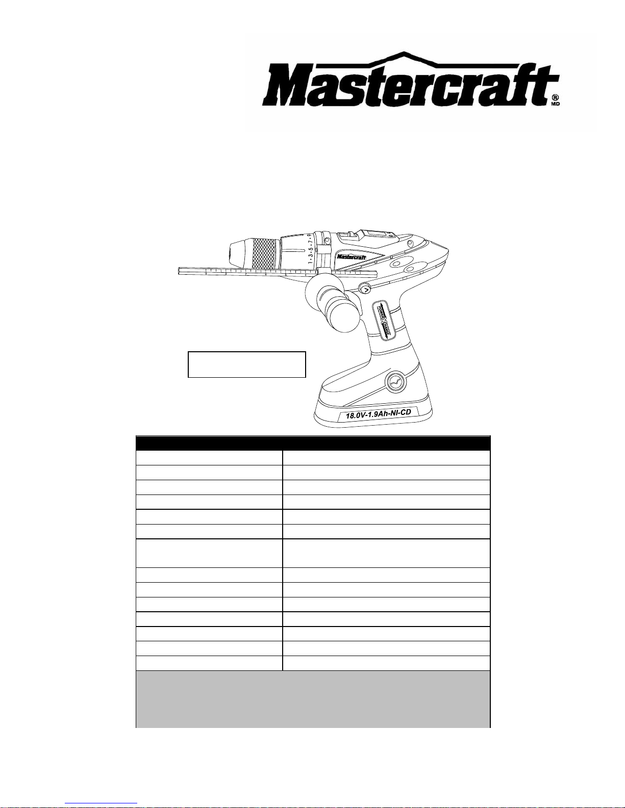
18 V Ni-Cd HAMMER DRILL
54-2903-2
Owner’s Manual
PRODUCT SPECIFICATIONS
Battery:
Two 18 V, 1.9Ah Nickel-cadmium
Maximum torque:
400 in-lb
Variable speed ranges:
0–400 & 0–2,000 RPM (no load)
Hammer speeds:
0–36,000 BPM
Torque clutch positions:
25 + drill + hammer modes
Keyless chuck:
1/2" (13 mm) single sleeve Jacobs®
Maximum drilling depth:
1/2" (13 mm) in steel
2 9/16" (6.5 cm) in wood
Charger:
1 hour diagnostic, Class 2
Charger input:
120 V AC, 60 Hz
Charger output:
14.4 to 18 V DC, 2.8 A (maximum)
Replacement chargers:
54-3103-0 (LED), 54-3101-4 (LCD)
Replacement battery:
54-3102-2 (Ni-Cd)
Replacement battery:
54-3100-6 (Lithium-ion)
Weight:
4 lb 6 oz (2.0 kg) without battery
NEED ASSISTANCE?
Call us on our toll-free Customer Support Line:
1-800-689-9928
Imported by Mastercraft Canada Toronto, Canada M4S 2B8
Patent Pending
Page 2

2
Product specifications ………….…………………………………………………….
1
Table of contents ……………………………………………………………………...
2
General safety warnings ……………………………………………………………..
3–4
Eye, ear & lung protection ……………………………………………………………
3–4
Electrical safety ……………………………………………………………………….
4
Power tool safety ……………………………………………………………………...
5–6
General safety rules …………………………………………………………………..
5
Work area ………………………………………………………………….…………..
5
Electrical safety ……………………………………………………………………….
5
Personal safety ………………………………………………………………………..
5–6
Use and care of power tools .………………………………………………………..
6
Service …………………………………………………………………………………
6
Specific safety rules …………………………………………………………………..
7
Battery & charger safety ………………………………………………………….….
8–9
Battery pack recycling ………………………………………………………………..
9
Symbols ………………………………………………………………………………..
10
Know your hammer drill ………………………………………………………………
11
Available accessories ………………………………………………………………...
11
Contents ……………………………………………………………………………….
12–13
Assembly and operating ……………………………………………………………..
14–31
Positioning the charger ……………………………………………………………….
14
Storing the charger ……………………………………………………………………
14
Charging the battery pack ……………………………………………………………
15–16
Installing a battery in the hammer drill ……………………………………………..
17
Adjusting the torque ………..…………………………………………………………
18
Installing the auxiliary side handle …………………………………………………..
19
Bit storage in auxiliary handle ……………………………………………………….
19
Installing the depth stop rod …………………………………………………………
20
Two-speed gear box switch ………………………………………………………….
20–21
Forward/reverse switch ………………………………………………………………
21
Spirit level ……………………………………………………………………………..
21–22
Variable-speed trigger switch ………………………………………………………..
22
Dual LED worklights ………………………………………………………………….
23
LCD display ……………………………………………………………………………
23
Installing bits …………………………………………………………………………..
24–25
Removing bits …………………………………………………………………………
25
Drilling ………………………………………………………………………………….
26–28
Drilling in concrete ……………………………………………………………………
28
Driving screws …………………………………………………………………………
28–29
Removing the chuck ………………………………………………………………….
29–30
Retightening a loose chuck ………………………………………………………….
30–31
Maintenance …………………………………………………………………………..
32–33
Exploded view …………………………………………………………………………
34
Parts list ………………………………………………………………………………..
35
Warranty ……………………………………………………………………….………
36–37
TABLE OF CONTENTS
Page 3
3
EYE, EAR & LUNG PROTECTION
This instruction manual includes the following:
General Safety Rules
Specific Safety Rules and Symbols
Functional Description
Assembly
Operation
Maintenance
Accessories
!
ALWAYS WEAR EYE PROTECTION THAT CONFORMS WITH CSA
REQUIREMENTS or ANSI SAFETY STANDARD Z87.1
FLYING DEBRIS can cause permanent eye damage. Prescription
eyeglasses ARE NOT a replacement for proper eye protection.
WARNING: Non-compliant eyewear can cause serious injury if
broken during the operation of a power tool.
SAVE THESE INSTRUCTIONS FOR REFERENCE
WARNING: Use hearing protection, particularly during extended
periods of operation of the tool, or if the operation is noisy.
!
GENERAL SAFETY WARNINGS
CAUTION: Before using this tool or any of its accessories, read this
manual and follow all Safety Rules and Operating Instructions.
!
Page 4
4
ELECTRICAL SAFETY
WARNING: To avoid electrical hazards, fire hazards or damage to the
tool, use proper circuit protection.
This tool is wired at the factory for 110–120 V operation. It must be
connected to a 110–120 V 15 A circuit that is protected by a time-delayed
fuse or circuit breaker. To avoid shock or fire, replace power cord
immediately if it is worn, cut or damaged in any way.
GENERAL SAFETY WARNINGS
WEAR A DUST MASK THAT IS DESIGNED TO BE USED WHEN
OPERATING A POWER TOOL IN A DUSTY ENVIRONMENT.
WARNING: Dust that is created by power sanding, sawing, grinding,
drilling, and other construction activities may contain chemicals that are
known to cause cancer, birth defects, or other genetic abnormalities. These
chemicals include:
Lead from lead-based paints
Crystalline silica from bricks, cement, and other masonry products
Arsenic and chromium from chemically treated lumber
The level of risk from exposure to these chemicals varies, according to how
often this type of work is performed. In order to reduce exposure to these
chemicals, work in a well-ventilated area, and use approved safety
equipment, such as a dust mask that is specifically designed to filter out
microscopic particles.
!
Page 5

5
GENERAL SAFETY RULES
WARNING: Read and understand
all instructions. Failure to follow all
instructions listed below may result in
electric shock, fire and/or serious personal
injury.
WORK AREA
Keep your work area clean and well lit.
Cluttered benches and dark areas invite
accidents.
Do not operate power tools in potentially
explosive environments, such as in the
presence of flammable liquids, gas or dust.
Power tools create sparks that may ignite
dust or fumes.
Keep bystanders, children and visitors
away while operating the tool. Distractions
can cause the operator to lose control.
ELECTRICAL SAFETY
Double insulated tools are equipped with a
polarized plug (one blade is wider than the
other). This plug will only fit into a
polarized plug one way.
If the plug does not fit into the outlet
properly, reverse the plug. If it still does not
fit, contact a qualified electrician to install a
polarized outlet. Do not alter the plug in
any way. Double insulation eliminates the
need for the three-pronged grounded
power cord and grounded power supply
system.
Avoid contact between the operator's body
and grounded surfaces such as pipes,
radiators, ranges, and refrigerators. There
is an increased risk of electric shock if the
operator's body is grounded.
Do not expose power tools to rain or wet
conditions. Water entering the power tool
will increase the risk of electric shock.
Do not abuse the cord. Do not use the
power cord to carry the tool or to pull the
plug out of the outlet. Keep the power cord
away from heat, oil, sharp edges, and
moving parts. Replace a damaged power
cord immediately. A damaged power cord
increases the risk of electric shock.
When operating a power tool outdoors,
use an outdoor-rated extension cord type
“W-A” or “W”. These cords are rated for
outdoor use and they reduce the risk of
electric shock.
PERSONAL SAFETY
Stay alert, be aware of the surroundings,
and use common sense when operating a
power tool. Do not use a power tool while
tired or under the influence of drugs,
alcohol, or medication. A moment of
inattention while operating a power tool
may result in serious personal injury.
Dress properly. Do not wear loose clothing
or jewellery.
Contain long hair. Keep hair, clothing, and
gloves away from moving parts. Loose
clothing, jewellery, or long hair can get
caught in moving parts.
!
POWER TOOL SAFETY
Page 6

6
PERSONAL SAFETY – cont’d
Avoid accidental start-ups. Verify that the
switch is in the OFF position before
plugging in the tool. Carrying a power tool
with a finger on the switch or plugging in a
tool that has the switch in the ON position
invites accidents.
Remove adjusting keys and wrenches
before turning the tool ON. A wrench or
key that is left attached to a rotating part of
the tool may result in personal injury.
Do not overreach. Keep proper footing and
balance at all times. Proper footing and
balance allows the operator to maintain
better control of the tool in unexpected
situations.
Use safety equipment. Always wear eye
protection.
Use a dust mask, non-skid safety shoes, a
hardhat, or hearing protection when
appropriate.
USE AND CARE OF POWER TOOLS
Use clamps or another practical means to
secure and support the workpiece to a
stable platform. Holding the work in a hand
or against the body is not stable, and may
lead to loss of control.
Do not force the tool. Use the correct tool
for the application. The correct tool will do
the job better and safer when used at the
rate that it was designed to work at.
Do not use a power tool if it cannot be
turned ON or OFF using the power switch.
A tool that cannot be controlled using the
switch is dangerous, and must be repaired.
Disconnect the plug from the outlet before
making any adjustments, changing
accessories, or storing the tool. Such
preventive safety measures reduce the risk
of accidental start-ups.
When power tools are not in use, store
them out of the reach of children or
untrained persons. Tools are dangerous in
the hands of untrained users.
Maintain tools with care. Keep cutting tools
sharp and clean. Properly maintained
cutting tools with sharp cutting edges are
less likely to bind, and are easier to
control.
Inspect the tool for misalignment or binding
of moving parts, broken parts, and any
other condition that may affect the
operation of the tool. If it is damaged, have
the tool serviced before using it. Many
accidents are caused by poorly maintained
tools.
Use only accessories that are
recommended by the manufacturer for this
model. Accessories that are suitable for
one tool may become hazardous when
used with another tool.
SERVICE
Tools servicing must be performed by
qualified personnel. Service or
maintenance performed by non-qualified
personnel could result in a risk of injury.
When servicing a tool, use only identical
replacement parts. Follow the instructions
in the Maintenance section of this Manual.
The use of unauthorized parts or failure to
follow the instructions in the Maintenance
section of this Manual may create a risk of
electric shock or injury.
POWER TOOL SAFETY
Page 7
7
WARNING: Know your hammer
drill. Do not plug in the charger or
install the battery in the tool until you
have read and understand this
Instruction Manual. Learn the tool’s
applications and limitations, as well as
the specific potential hazards related to
this tool. Following this rule will reduce the
risk of electric shock, fire, or serious injury.
Always wear eye protection.
Any power tool can throw
foreign objects into your eyes
and cause permanent eye damage.
ALWAYS wear safety goggles (not
glasses) that comply with ANSI safety
standard Z87.1. Everyday glasses have
only impact resistant lenses. They ARE
NOT safety glasses.
WARNING: Glasses or goggles
not in compliance with ANSI Z87.1
could cause serious injury when they
break.
WARNING: Always use a safety
shield, hearing protection and dust
mask when operating the drill in
“hammer” mode.
Use only hammer drill bits and accessories
that are designed for use with a hammer
drill when using this hammer drill in the
hammer mode. Standard drill bits are NOT
designed for use in a hammer drill and
MUST NOT be used with a hammer drill.
They may shatter and possibly cause
serious injury.
Do not drill material too small to be
securely held.
Always keep hands out of the path of the
drill bit. Avoid awkward hand positions
where a sudden slip could cause your
hand to move into the path of the drill bit.
Secure workpiece. Use clamps or a vice to
hold the workpiece. It is safer than using
your hand and it frees both hands to
operate the tool.
Make sure there are no nails or foreign
objects in the part of the workpiece to be
drilled.
To avoid injury from accidental starting,
always remove the battery from the tool
before installing or removing a drill bit.
Do not install or use any drill bit that
exceeds 7” (17.5 cm) in length or extends
more than 6” (15 cm) beyond the chuck
jaws. They can bend or break suddenly.
Before starting the operation, jog the drill
switch to make sure the drill bit does not
wobble or vibrate.
Do not use fly cutters or multiple-part hole
cutters, because they can come apart or
become unbalanced during use.
Make sure the spindle has come to a
complete stop before touching the chuck
or attempting to change the drill bit.
Always make sure the chuck is tight and
the drill bit firmly tightened in the chuck
before starting drill.
SPECIFIC SAFETY RULES
!
!
SAVE THESE INSTRUCTIONS FOR REFERENCE
!
Page 8

8
WARNING: Only use the
PowerXchange diagnostic charger to
charge the following Mastercraft
batteries:
● 18 V Ni-Cd #54-3102-2
● 18 V Lithium-ion #54-3100-6
Charging any other batteries may damage
the charger, and possibly cause serious
injury. Check your PowerXchange
diagnostic charger manual for other
batteries that may be charged in the
PowerXchange battery family.
Do not store or carry battery in a manner in
which metal objects could contact the
exposed metal end. Do not place battery in
aprons, pockets, drawers, etc. with loose
nails, screws, keys etc. The battery could
short circuit causing a fire, personal injury
or damage to the battery.
Never attempt to open the battery for any
reason. If the housing of the battery breaks
or cracks, immediately discontinue use
and do not recharge.
Do not charge the battery if it is wet or
shows any evidence of corrosion.
A small leakage from the battery may
occur under extreme usage, charging or
temperature conditions. This does not
indicate a failure. However, if the outer
seal is broken and this leakage gets on
your skin, follow these steps:
1. Wash immediately with soap and
water.
2. Neutralize with a mild acid such as
lemon juice or vinegar.
3. If liquid gets into your eyes, flush
immediately with clean water for a
minimum of 10 minutes and seek
medical attention.
NOTE: The battery liquid is slightly acidic.
Do not incinerate the battery. It can
explode in a fire.
Do not use an extension cord. Plug the
charger cord directly into an electrical
outlet.
Use the charger only in a standard
110–120 V, 60 Hz electrical outlet.
Do not use the charger in wet or damp
conditions. It is intended for indoor use
only. Do not use the charger near sinks or
tubs. Do not immerse the charger in water.
Do not allow the cord to hang over the
edge of a table or counter or touch hot
surfaces. The charger should be placed
away from sinks and hot surfaces.
Do not use charger to charge any batteries
other than the hammer drill batteries
specified for that charger. Other batteries
may explode.
Do not operate charger if cord or plug is
damaged. Replace damaged cord and
plug immediately.
Do not operate charger if it has received a
sharp blow, been dropped or otherwise
damaged in any way. Have a qualified
technician examine the charger and repair
it if necessary. Do not disassemble the
charger.
BATTERY & CHARGER SAFETY
!
Page 9

9
Do NOT charge Ni-Cd or Ni-MH batteries
when the temperature of the work area or
the battery is above 55° C (131° F).
Do NOT charge Li-ion batteries when the
work area or the battery temperature is at
or below 0°C (32° F) or above 45° C
(113° F).
Unplug the charger when not in use and
before cleaning or maintenance.
BATTERY PACK RECYCLING
To preserve our natural resources, please
recycle or dispose of batteries properly.
The batteries accompanying this tool may
contain chemicals and metals that are
harmful to the environment. Never dispose
of re-chargeable batteries in your normal
household garbage or in landfill sites as
they will add to the pollution of the
environment.
Please return all defective rechargeable
battery packs to your local Canadian
Tire™ store for recycling. If you do not
have a Canadian Tire™ store in your area,
please call 1-800-822-8837 for the location
of your nearest RBRC battery recycling
location.
Consult your local waste authority for
information regarding additional available
recycling and disposal options.
BATTERY & CHARGER SAFETY
NOTE: See Pages 32 & 33 for
detailed information concerning
preparation for recycling battery packs
and exercising the Ni-Cd battery pack
for peak performance.
Page 10
10
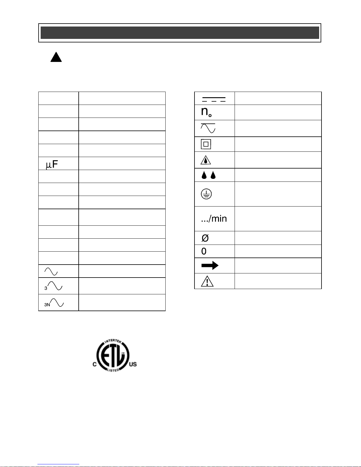
V
Volts
A
Amperes
Hz
Hertz
W
Watts
kW
Kilowatts
Microfarads
L
Litres
kg
Kilograms
H
Hours
N/cm2
Newtons per square
centimetre
Pa
Pascals
Min
Minutes
S
Seconds
Alternating current
Three-phase alternating
current
Three-phase alternating
current with neutral
Direct current
No load speed
Alternating or direct
current
Class II construction
Splash-proof
construction
Watertight construction
Protective grounding at
grounding terminal,
Class I tools
Revolutions or
reciprocations per
minute
Diameter
Off position
Arrow
Warning symbol
SYMBOLS
WARNING: Some of the following symbols may appear on the tool.
Study these symbols and learn their meaning. Proper interpretation of these
symbols will allow for more efficient and safer operation of this tool.
!
3042597
HOMOLOGUÉ
This symbol designates that this tool is
listed with Canadian requirements by ETL
Testing Laboratories, Inc.
Conforms to UL Std. 60745-1, 60745-1-1,
60745-2-2. Certified to CAN/CSA Std.
C22.2 No. 60745-1, 60745-2-1, 60745-2-2.
Page 11
11
AVAILABLE ACCESSORIES
WARNING: Use only accessories
that are recommended for this hammer
drill. Follow the instructions that
accompany the accessories. The use of
improper accessories may result in
injury to the operator or damage to the
hammer drill.
Before using any accessory, carefully read
the instructions or the owner’s manual for
the accessory.
Drill bits
Hammer drill bits
Screwdriver bits
Nut drivers
WARNING: If any part is missing or
damaged, do not plug charger into the
power source or install the battery in the
tool until the missing or damaged part is
replaced.
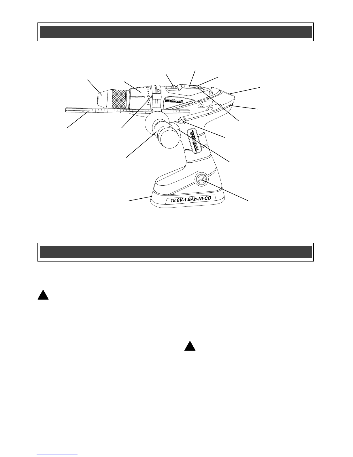
KNOW YOUR HAMMER DRILL
ACCESSORIES
!
!
LED lights
Depth
stop rod
Chuck
Variable speed
trigger switch
Forward/reverse
button
LCD
display
Gear box
switch
Battery release
button
Torque
clutch
LED Light
switch
LCD
Display switch
Spirit
level
Air vents
Auxiliary handle
with bit storage
Battery
Page 12
12
CONTENTS
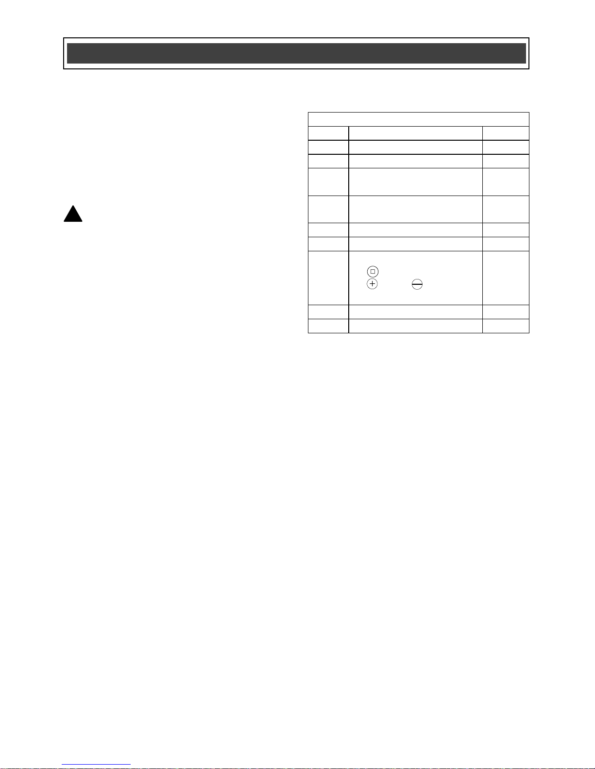
Carefully unpack the hammer drill.
Compare the contents against the
“HAMMER DRILL COMPONENTS” chart
at right.
NOTE: See illustration of hammer drill on
Page 13.
WARNING: To avoid fire or toxic
reaction, never use gasoline, naphtha,
acetone, lacquer thinner or similar
highly volatile solvents to clean the
tool.
!
CONTENTS
HAMMER DRILL COMPONENTS
KEY
DESCRIPTION
QTY
A
Hammer drill
1
B
Depth stop rod
1
C
Depth stop rod
mounting clamp
1
D
1-hour LED diagnostic
charger
1
E
Blow-moulded case
1
F
18 V Ni-Cd battery
2
G
Screwdriver bits
● #1/#2
● #2 & 15/64"
(6 mm)
1
1
H
Auxiliary handle
1
Owner’s manual
1
Page 13

13
CONTENTS
Page 14

14
POSITIONING THE CHARGER
Position the charger (1) in a dry location
within 5’ (1.5 m) of a 110–120 V 60 Hz
electrical outlet. The charger can either be
placed with its rubber feet on a table or
workbench, or hung on a wall.
1. To hang the charger on a wall, place 2
nails or screws (1) in the wall where
you want the charger to hang (Fig. 1).
NOTE: The nail or screw heads must be
1/4" (6.4 mm) in diameter, and the head
must be left 3/8" (8.3 mm) out from the
wall, placed 3" (7.62 cm) apart.
2. Place the large mounting access hole
(2) over the nail or screw head and
slide the charger downward until it
hangs on the nail or screw.
STORING THE CHARGER
To store the charger, simply wrap the cord
around the charger (1) and insert the cord
into the cord clip (2) (Fig. 2).
ASSEMBLY AND OPERATING
Fig. 1
Fig. 2
Page 15

15
CHARGING THE BATTERY PACK
WARNING: Only use the
PowerXchange diagnostic charger to
charge the following Mastercraft
batteries:
● 18 V Ni-Cd #54-3102-2
● 18 V Lithium-ion #54-3100-6
Charging any other batteries may damage
the charger, and possibly cause serious
injury.
1. To charge the battery, place the
charger (1) in a dry location near a
110–120 V, 60 Hz electrical outlet
(Fig. 3).
2. Place the battery stem (2) into the
matching cavity (3) in the top of the
charger.
NOTE: Make sure the battery is pressed
fully onto the charger as far as it will go.
3. Plug the battery charger into the 110–
120 V, 60 Hz wall receptacle.
NOTE: Do NOT charge Ni-Cd or Ni-MH
batteries when the temperature of the work
area or the battery is above 55° C
(131° F). Do NOT charge Li-ion batteries
when the work area or the battery
temperature is at or below 0° C (32° F) or
above 45° C (113° F).
When the battery charger is plugged into a
“live” receptacle, the battery charger will
begin charging the battery. The red LED
(4) and the green LED (5) on the top of the
charger will indicate the charging status
(Fig. 4).
ASSEMBLY AND OPERATING
!
Fig. 4
Fig. 3
Page 16

16
CHARGING THE BATTERY PACK – cont’d
CHARGER LED FUNCTIONS (Fig. 4a)
Power ON
The green LED will stay ON when the
charger is plugged into a ”live” power
source.
Battery partially charged
The red LED will flash during charging.
Battery fully charged
When a Ni-Cd or Ni-MH battery is
approximately 98% charged, the red LED
will turn OFF and the green LED will blink
for about 1 hour then stay continuously
ON, indicating the battery is fully charged.
The blinking green LED indicates the
charger is in trickle charge mode while
completing the charging cycle.
When a Li-ion battery is nearly fully
charged, the red LED will turn OFF and the
green LED will blink for a few minutes
while completing the charge.
NOTE: You may use the battery as soon
as the green LED begins to flash, as the
battery will be at least 98% charged.
Defective battery
The red LED will stay ON when a defective
battery is detected and it should be
replaced.
Too hot or too cold
Both the red LED and the green LED will
stay ON when the work area or battery
temperature is either too high or too low.
Remove the battery from the charger and
let it sit at room temperature 21° C (70° F)
for about one hour, and resume charging.
ASSEMBLY AND OPERATING
Red
light
Green
light Function
—
---
---
—
—
—
Power
ON
Battery
charging
Trickle
charging
Defective
battery
Too hot or
too cold
Flashing
Flashing
ON
On
On
On
Fig. 4a
Page 17

17
INSTALLING A BATTERY IN THE
HAMMER DRILL
1. Remove the discharged battery (1)
from the tool by pressing on one the
battery release buttons (2) on the
sides of the drill handle (Fig. 5).
NOTE: There is one battery release button
on each side of the handle. It is only
necessary to press one of the buttons to
release the battery.
2. Pull the battery out of the tool handle
(3).
3. Slide the fully charged battery into the
matching cavity in the tool handle
where the discharged battery has
been removed.
NOTE: Make sure the battery is fully
engaged with the mounting slots in the tool
handle. The battery release buttons will
“click” into place when the battery is fully
installed.
WARNING: Do not immerse battery
pack in water. Sudden cooling could cause
hot battery to explode or leak.
ASSEMBLY AND OPERATING
!
Fig. 5
Page 18

18
ADJUSTING THE TORQUE
Your drill is equipped with an adjustable
torque clutch for driving different types of
screws into different types of materials. It
also has settings for “drilling” and “hammer
drilling”. The proper setting depends upon
the type of material and size of screw
being used and the function required.
Adjust the torque setting as follows:
1. Identify the torque settings located on
the torque adjustment ring (1) (Fig. 6).
2. Rotate adjustment ring to align the
correct torque setting number with the
torque indicator arrow (2). See the
chart on the following page for correct
torque settings.
1–5 For driving small screws
6–10 For driving medium sized screws
into soft materials
11–15 For driving screws into soft &
medium-density materials
16–20 For driving screws into
hardwood
21–25 For driving large screws
For drilling. This position is
marked with a drill bit icon (3) on the
torque adjustment ring (Fig. 7).
Use the highest setting
indicated by a hammer icon (4) for
hammer mode.
ASSEMBLY AND OPERATING ASSEMBLY AND OPERATING
Fig. 6
Fig. 7
Page 19

19
INSTALLING THE AUXILIARY SIDE
HANDLE
Install the auxiliary handle (1) for twohanded operation of the drill (Fig. 8). This
is particularly important for hammer drilling
in concrete.
NOTE: The auxiliary handle can be
installed on either the left or right side of
the hammer drill.
1. Insert the threaded mounting screw
(2) through the depth stop rod clamp
(3) and into the threaded hole in the
drill housing (4).
NOTE: Make sure the key in the clamp is
aligned with the matching slot in the drill
housing.
2. Turn the auxiliary handle clockwise to
tighten it into the drill housing.
NOTE: Tighten the handle by hand only.
Do NOT overtighten the handle or you will
damage the handle or the housing.
BIT STORAGE IN AUXILIARY HANDLE
Screwdriver bits and drill bits can be stored
in the auxiliary handle.
1. To store bits in the auxiliary handle
(1), remove the end cap (2) by turning
it counter-clockwise (Fig. 9).
2. Insert the bits to be stored in the
handle.
3. Insert the end cap into the handle and
tighten it into place by turning it
clockwise.
ASSEMBLY AND OPERATING
Fig. 8
Fig. 9
Page 20

20
INSTALLING THE DEPTH STOP ROD
The depth stop rod is used as a gauge to
control the depth of the drilled hole. The
depth stop rod can be used with the
hammer drill in either the normal drilling
mode or in the hammer drill mode.
1. Turn the auxiliary handle (1) counter
clockwise about three turns to open
the depth stop rod mounting clamp (2)
(Fig. 10).
2. Insert hexagonal end of depth rod (3)
into the matching hole (4) in the depth
stop rod mounting clamp.
3. Position the depth stop rod so the tip
of the round end will contact the
workpiece when the drill reaches the
appropriate depth.
4. When the depth stop rod is properly
positioned, tighten the depth stop rod
mounting clamp by turning the
auxiliary handle clockwise. Tighten by
hand only.
NOTE: Tighten the handle by hand only.
Do NOT overtighten or you will damage
the handle or housing.
TWO-SPEED GEAR BOX SWITCH
Set the speed-control switch (1) to the
desired speed (Fig. 11). Slide the speedcontrol switch FORWARD for low-speed
operation. Slide the speed-control switch
BACK for high-speed operation.
ASSEMBLY AND OPERATING
Fig. 10
Fig. 11
Page 21

21
TWO SPEED GEAR BOX SWITCH – Cont’d
NOTES:
a) Use low-speed setting for drilling large
holes and for driving screws.
b) Use high-speed setting for drilling
smaller holes.
c) Do NOT change the speed-control
switch position while drill is turned ON.
Damage to the gears may result.
FORWARD/REVERSE SWITCH
The forward/reverse switch (1) is
conveniently mounted above the trigger
switch (2) (Fig. 12). To make the drill rotate
clockwise for drilling or driving screws,
push the forward/reverse switch to the left.
To make the drill rotate counter-clockwise
for removing screws, push the
forward/reverse switch to the right.
NOTES:
a) The auxiliary handle has been removed
for illustrative purposes.
b) Never change the position of the
forward/reverse switch while chuck is
turning.
c) The trigger switch will NOT function with
the forward/reverse switch in the middle
position.
SPIRIT LEVEL
The drill is equipped with a dual reading
horizontal/vertical level to assist in keeping
the drill “level” while drilling horizontal and
vertical holes.
The horizontal level (1) is located in the top
of the drill housing (Fig. 13). The vertical
level (2) is located on the rear of the drill
housing.
ASSEMBLY AND OPERATING
Fig. 12
Fig. 13
Page 22

22
SPIRIT LEVEL – cont’d
To maintain a horizontal drilling position,
hold the drill so the horizontal level bubble
(3) is centred in the level indicator circle (4)
(Fig. 14). To maintain a vertical drilling
position, hold the drill so the vertical level
bubble (5) is centred in the level indicator
circle (6) (Fig. 15).
VARIABLE-SPEED TRIGGER SWITCH
This drill is equipped with a variable-speed
ON/OFF trigger switch.
1. To start drill, gently squeeze the
trigger switch (1) (Fig. 16).
NOTE: The drill will turn at its slowest
speed when the trigger switch is
depressed slightly. The drill will turn at its
fastest speed when the trigger switch is
fully depressed.
2. To stop the drill, release the trigger
switch.
NOTE: Drilling at a slow speed for an
extended period of time may cause the drill
motor or the battery pack to overheat. If
either the drill or the battery get hot, stop
drilling and allow them to cool for at least
15 minutes.
ASSEMBLY AND OPERATING
Fig. 14
Fig. 15
Fig. 16
Page 23

23
DUAL LED WORKLIGHTS
Dual LED worklights (1) are located behind
the torque collar (2) (Fig. 17). The LED
switch button (3) is located below the LCD
panel on the top of the drill (Fig. 18).
1. To turn the LED lights ON, first press
the LCD display switch (5) once, then
press the LED switch (3) once. The
LED lights will turn OFF automatically
when the tool is not operated for
approximately 5 minutes.
2. To turn the LED lights OFF, press the
LED switch again.
LCD DISPLAY
This hammer drill is equipped with an LCD
panel (4) in the top of the drill housing
(Fig. 19).
1. To turn the display ON, press the
display button (5) once. To turn the
display OFF, press the display button
again.
2. The light icon (6) will become visible
when the LED worklights are turned
ON.
3. The battery icon (7) indicates the
amount of charge remaining in the
battery. Each charge bar displayed
indicates approximately 10% charge
remaining in the battery. A total of 10
charge bars indicates a fully charged
battery.
ASSEMBLY AND OPERATING
Fig. 18
Fig. 19
Fig. 17
Page 24

24
INSTALLING DRILL BITS
WARNING: Never hold the chuck
body with one hand and use the drill
power to rotate the drill body to loosen
or tighten bits. Serious injury may
result.
This hammer drill is equipped with a
Jacobs® single-sleeve keyless
Hammerlock® chuck.
This chuck is designed to provide easy
one-handed tightening and loosening of
the chuck jaws. It also provides a positive
bit locking mechanism that prevents the bit
from slipping during the high vibration
hammer drilling action.
1. To open the keyless drill chuck, grasp
and hold the chuck body (1) and
rotate it in a counter-clockwise
direction until the chuck jaws (2) open
wide enough to accept the bit (3)
(Fig. 20).
NOTE: The drill spindle will automatically
lock when the drill is stopped.
2. Insert the bit into the chuck the full
length of the jaws. Raise the front of
your drill slightly to prevent the bit from
falling out of the chuck jaws.
3. Tighten the chuck jaws onto the bit by
turning the chuck body in a clockwise
direction.
NOTE: Make sure the bit is properly
aligned in the jaws and NOT at an angle.
An improperly aligned bit could be thrown
from the chuck when the drill is started.
Make sure the chuck jaws grasp the flat
sides of a screwdriver bit.
ASSEMBLY AND OPERATING
Fig. 20
!
Page 25

25
INSTALLING DRILL BITS – cont’d
4. Finish tightening the chuck jaws.
Firmly grasp the chuck body with your
hand and rotate it in a clockwise
direction.
NOTES:
a) The automatic spindle lock will prevent
the spindle from rotating while the chuck
body is being tightened.
b) As the chuck jaws begin to tighten on
the bit, you will hear a clicking sound.
Continue to rotate the chuck body until the
clicking stops and you can no longer turn it
any further BY HAND.
c) Hand-tighten chuck body. Do NOT use
pliers. You will damage the chuck.
WARNING: Do not insert drill bit
into chuck and tighten as shown in
Fig. 21. The drill bit MUST be properly
inserted with all three of the chuck jaws
holding the bit centred in the chuck. Failure
to properly insert drill bit could cause the
drill bit to be thrown from the chuck,
resulting in possible serious injury or
damage to the chuck.
REMOVING BITS
1. To open the keyless drill chuck, grasp
and hold the chuck collar and rotate it
in a counter-clockwise direction until
the chuck jaws open and release the
bit.
2. Remove the bit.
!
ASSEMBLY AND OPERATING
Fig. 21
Page 26

26
DRILLING
When drilling into smooth, hard surfaces
such as metal, use a centre punch to mark
the desired hole location. This will prevent
the drill bit from slipping off centre as the
hole is started.
ASSEMBLY AND OPERATING
!
For safety reasons, the operator
must read the sections of this
Owner’s Manual entitled “GENERAL
SAFETY WARNINGS”, “POWER
TOOL SAFETY”, “SPECIFIC SAFETY
RULES”, “BATTERY & CHARGER
SAFETY” and “SYMBOLS” before
using this hammer drill.
Verify the following every time the
hammer drill is used:
1. Safety glasses, safety goggles,
or face shield is being worn.
2. Hearing protection and dust
mask are being worn when
using the drill in “hammer”
mode.
3. The chuck has not worked loose
on the spindle.
4. A hammer rated drill bit is being
used when drilling in “hammer”
mode.
5. The bit is in good condition, and
is properly tightened into the
chuck.
Failure to observe these safety rules
will significantly increase the risk of
injury.
WARNING
!
Page 27

27
DRILLING – cont’d
The workpiece to be drilled should be
secured in a vice or with clamps to keep it
from turning as the bit rotates (Fig. 22).
1. Check the drill bit to make sure it is
firmly locked into the drill chuck, and
verify that the forward/reverse switch
is in the forward position.
2. Set torque clutch to the drilling
position.
3. Hold the drill firmly with both hands
whenever possible. Use one hand to
grasp the handle and switch, and the
other to grasp the body of the drill or
the auxiliary handle if it is installed.
NOTE: Make sure the hand placed on the
body of the drill does not cover the air
vents. Covering these air vents will reduce
motor cooling, and possibly lead to
overheating the motor.
4. While holding the drill firmly, place the
point of the drill bit at the point to be
drilled. Squeeze the switch trigger to
start the drill.
NOTES:
a) Always use a higher drill speed when
drilling small holes. Use a slower drill
speed when drilling large holes.
b) Use a masonry bit with the drill in
hammer mode ONLY when drilling in
concrete or masonry.
5. Move the drill bit into the workpiece
applying only enough pressure to
keep the bit cutting. Do not force the
drill bit or apply sideways pressure to
elongate the hole.
ASSEMBLY AND OPERATING
Fig. 22
Page 28

28
DRILLING – cont’d
WARNING: Be prepared for
binding and bit breakthrough. When
these situations occur, the drill bit has a
tendency to grab the workpiece. This
action will kick the drill opposite to the
direction of drill bit rotation, and could
cause loss of control when breaking
through material as you complete
drilling the hole. If you are not prepared,
this loss of control can result in serious
injury.
When drilling metals, use a light oil on the
drill bit to keep it from overheating. The oil
will prolong the life of the drill bit and
improve the cutting action. If the bit jams in
the workpiece, or if the drill stalls, release
the trigger switch immediately. Remove the
bit from the workpiece and determine the
reason for jamming.
DRILLING IN CONCRETE
WARNING: Always use a face
shield and hearing protection when
drilling in concrete.
Always use the hammer mode for faster
drilling in concrete. Use slower speeds
when using bits over 1/2” (13 mm) in
diameter. Always use carbide tipped
masonry bits.
DRIVING SCREWS
When driving screws, care must be taken
to use the bit that correctly fits the screw
being driven. Make sure you use the
largest bit size that will properly fit into the
head of the screw.
!
ASSEMBLY AND OPERATING
!
Page 29

29
DRIVING SCREWS – cont’d
1. Select the correct screwdriver bit for
the screw being driven.
2. Fasten the screwdriver bit into the
chuck, making sure the flat sides of
the bit are gripped by the chuck jaws.
3. Set the torque clutch to the
appropriate setting based on the chart
on Page 18.
NOTE: If material is particularly soft or
porous, set the torque clutch to a lower
setting to avoid overdriving the screw.
When driving small screws in soft wood
(torque settings 1-5), be ready to release
the trigger to prevent overdriving the
screw.
4. If the screw is driven too far into the
workpiece before the clutch releases,
set the clutch to a lower setting, and
do not pull the trigger switch fully
back. If the screw is not driven far
enough into the workpiece, set the
clutch to a higher setting.
NOTE: Do not continue to drive the screw
once the clutch has released. This causes
unnecessary wear of the clutch.
REMOVING THE CHUCK
To remove the chuck:
1. Remove the battery pack from the
drill.
2. Insert a 5/16” (8 mm) or larger hex key
(1) into the chuck (2) and tighten the
chuck jaws securely (Fig. 23). Make
sure each of the chuck jaws (3) is
seated on the flat surfaces of the hex
key.
ASSEMBLY AND OPERATING
Fig. 23
Page 30

30
REMOVING THE CHUCK – cont’d
3. Tap the hex key sharply with a mallet
(4) in a clockwise direction. This action
will loosen the screw in the chuck for
easy removal.
4. Open chuck jaws and remove the hex
key.
5. Open the chuck jaws as far as
possible.
6. Remove the chuck screw using a
#2 screwdriver (Fig. 24).
NOTE: Turn the screw CLOCKWISE to
remove it. This screw has a left-handed
thread.
7. Insert the hex key into the chuck and
tighten jaws of chuck securely
(Fig. 25). Tap the hex key sharply with
a mallet in a COUNTER-CLOCKWISE
direction. This will loosen the chuck on
the spindle. The chuck can now be
unscrewed and removed from the
spindle by hand.
RETIGHTENING A LOOSE CHUCK
After installing a chuck that has previously
been removed, the chuck may become
loose on the spindle and develop a
wobble. Also, the chuck screw may
become loose, causing the chuck jaws to
bind and preventing them from closing. To
tighten the chuck, follow these steps:
1. Insert the hex key into the chuck and
tighten the chuck securely.
ASSEMBLY AND OPERATING
Fig. 24
Fig. 25
Page 31

31
RETIGHTENING A LOOSE CHUCK – cont’d
2. Tap the hex key sharply with a mallet
in a CLOCKWISE direction (Fig. 26).
This will tighten the chuck on the
spindle.
3. Open the chuck jaws and remove the
hex key.
4. Tighten the chuck screw using a #2
screwdriver.
NOTE: Turn screw COUNTERCLOCKWISE to tighten it. This screw has
a left-handed thread.
ASSEMBLY AND OPERATING
Fig. 26
Page 32

32
GENERAL
WARNING: When servicing, use
only identical replacement parts. The
use of any other part may create a
hazard or cause product damage.
DO NOT use solvents when cleaning
plastic parts. Plastics are susceptible to
damage from various types of commercial
solvents and may be damaged by their
use. Use a clean cloth to remove dirt, dust,
oil, grease etc.
WARNING: Do not allow brake
fluids, gasoline, petroleum-based
products, penetrating oils, etc. to come
into contact with plastic parts. They
contain chemicals that can damage,
weaken or destroy plastic.
DO NOT abuse power tools. Abusive
practices can damage the tool and the
workpiece.
WARNING: DO NOT attempt to
modify tools or create accessories. Any
such alteration or modification is
misuse and could result in a hazardous
condition leading to possible serious
injury. It will also void the warranty.
LUBRICATION
All of the bearings in this tool are
lubricated with a sufficient amount of highgrade lubricant for the life of the unit under
normal conditions. Therefore, no further
lubrication is required.
BATTERY PACK REMOVAL AND
PREPARATION FOR RECYCLING
To preserve our natural resources, please
recycle or dispose of batteries properly.
The batteries accompanying this tool may
contain chemicals and metals that are
harmful to the environment. Never dispose
of rechargeable batteries in your normal
household garbage or in landfill sites,
because they will add to the pollution of
the environment.
Consult your local waste authority for
information regarding available recycling
and disposal options.
WARNING: Upon removal of the
battery pack, cover the terminals of the
battery pack with electrical tape or
heavy-duty adhesive tape. Never touch
both terminals with metal objects or
body parts, because a short circuit may
result. Keep away from children. Do not
attempt to destroy or disassemble
battery pack or remove any of its
components. Rechargeable batteries
must be recycled or disposed of
properly. Failure to comply with these
warnings could result in fire and
serious injury.
MAINTENANCE
! ! !
!
Page 33

33
NICKEL-CADMIUM BATTERY
MAINTENANCE
Nickel-cadmium batteries are powerful,
rugged and provide hundreds of
charge/discharge cycles if properly
maintained and periodically ‘exercised’.
Exercising is required to recover most of
the capacity lost during usage. This
process reduces the size of the active
cadmium hydroxide crystals on the anode,
to expose the entire surface area and
restore capacity.
How to care for your Nickel-cadmium
battery
1. Never allow a battery to freeze.
2. Never charge a Ni-CD or Ni-MH
battery that has been stored at
temperatures above 55° C (131° F).
Allow it to sit at room temperature for
at least 30 minutes before charging.
3. Do not charge a battery if it feels
warm to the touch.
4. Never charge a battery after a short
use. Let it sit until it is needed again.
5. Never charge the battery until the tool
in which it is being used cannot
produce useful work.
HOW TO EXERCISE A NICKELCADMIUM BATTERY
NOTE: Ni-Cd and Ni-Mh batteries have a
self discharge rate of approximately 1%
per day. The self discharge rate depends
upon the temperature.
1. Every two months or after 30
charge/discharge cycles, whichever
comes first, fully discharge your
battery. To fully discharge the battery,
place it in the tool that it came with
and work with the tool until it nearly
stops and no longer produces useful
action.
2. If the tool came in a kit with a
worklight, insert the battery into the
light. Turn the switch ON and leave it
ON until the filament is cherry red.
3. Let the battery rest for 30 minutes at
room temperature 21° C (70° F)
before charging.
4. Charge the fully discharged battery
for approximately 1 hour at 21° C
(70° F).
LITHIUM-ION BATTERY MAINTENANCE
Lithium-ion batteries share many
characteristics with Nickel-Cadmium
batteries.
The major characteristic that is NOT
shared with Nickel-Cadmium batteries is
that Lithium-ion batteries do not have a
“memory” and do not require to be
completely discharged periodically. It is
recommended that you charge your
Lithium-ion batteries after each use so
they will be fully charged when needed.
NOTE: A fully charged battery will loose
about 2% of its charge per month during
storage.
MAINTENANCE
Page 34

34
EXPLODED VIEW
Page 35

35
WARNING: When servicing, use only Mastercraft
®
replacement parts. The use of
any other parts may create a safety hazard or cause damage to the hammer drill.
Any attempt to repair or replace electrical parts on this hammer drill may create a safety
hazard unless repairs are performed by a qualified technician. For more information, call
the Toll-free Helpline, at 1-800-689-9928.
Always order by PART NUMBER, not by key number.
Key #
Part #
Part Name
Quantity
1
6516602033
Chuck screw
1
2
2800130101
Chuck
1
3
3100150101
Gear box
1
4
6511000812
Screw M5x8
2
5
2500200101
Motor assembly
1
6
4400700101
Speed selector button
1
7
4403890101
LED holder
1
8
4403900101
Depth rod clamp
1
9
5401980101
Depth rod
1
10
5800380101
Auxiliary handle
1
11
4403910101
Auxiliary handle end cap
1
12
5200990101
Decorative enclosure - left
1
13
6411391214
Screw ST3.9x12
1
14
3500420101
LCD display
1
15
4300710101
Left enclosure
1
16
8600840101
Spirit level
1
17
4403930101
Spirit level cover
1
18
3400480101
PCB
1
19
4403940101
Forward/reverse button
1
20
2700050301
Switch assembly
1
21
3601820101
Forward/reverse button retainer
1
22
5201000101
Decorative enclosure – right
1
23
6411391414
Screw ST3.9x14
2
24
6411391413
Screw ST3.9x14
9
25
4300720101
Right enclosure
1
26
2000070101
Battery pack
2
PARTS LIST
!
Page 36

36
3-Year Limited Warranty
This Mastercraft product is guaranteed for a period of 3 years from the date of
original retail purchase against defects in workmanship and materials, except for the
following components:
a) Component A: Batteries, chargers and carrying cases, which are
guaranteed for a period of 2 years from the date of original retail purchase
against defects in workmanship and materials;
b) Component B: Accessories which are guaranteed for a period of 1 year
from the date of original retail purchase against defects in workmanship
and materials.
Subject to the conditions and limitations described below, this product, if returned to
us with proof of purchase within the stated warranty period and is covered under
this warranty, will be repaired or replaced (with the same model, or one of equal
value or specification),at our option. We will bear the cost of any repair or
replacement and any costs of labour relating thereto.
These warranties are subject to the following conditions and limitations:
a) A bill of sale verifying the purchase and the purchase date must be
provided;
b) This warranty will not apply to any product or part thereof that is worn,
broken or that has become inoperative due to abuse, misuse, accidental
damage, neglect or lack of proper installation, operation or maintenance
(as outlined in the applicable owner’s manual or operating instructions) or
that is being used for industrial, professional, commercial or rental
purposes;
c) This warranty will not apply to normal wear and tear or to expendable parts
or accessories that may be supplied with the product that are expected to
become inoperative or usable after a reasonable period of use;
d) This warranty will not apply to routine maintenance and consumable items
such as, including but not limited to, fuel, lubricants, vacuum bags, blades,
belts, sandpaper, bits, fluids, tune-ups or adjustments;
e) This warranty will not apply where damage is caused by repairs made or
attempted by others (i.e.: persons not authorized by the manufacturer);
f) This warranty will not apply to any product that was sold to the original
purchaser as a reconditioned or refurbished product (unless specified
otherwise in writing);
Page 1 of 2
Page 37

37
Rev 1.1 15/01/2008
3-Year Limited Warranty – cont’d
These warranties are subject to the following conditions and limitations:
g) This warranty will not apply to any product or part thereof if any part
from another manufacturer is installed therein or any repairs or
alterations have been made or attempted by unauthorized persons;
h) This warranty will not apply to normal deterioration of the exterior
finish, such as, including but not limited to, scratches, dents, paint
chips, or to any corrosion or discoloring by heat, abrasive and
chemical cleaners; and
i) This warranty will not apply to component parts sold by and identified
as the product or company, which shall be covered under the product
manufacturer’s warranty, if any.
Additional Limitations
This warranty applies only to the original purchaser, and cannot be transferred.
Neither the retailer not the manufacturer shall be liable for any other expense, loss
or damage, including, without limitation, but not limited to any indirect, incidental,
consequential or exemplary damages arising in connection with the sale, use or
inability to use this product.
Notice to Consumer
This warranty gives you specific legal rights, and you may have other rights, which
may vary from province to province. The provisions contained in this warranty are
not intended to limit, modify, take away from, disclaim or exclude any statutory
warranties set forth in any applicable provincial or federal legislation.
Mastercraft is a superior line of products selected for their workmanship and
materials. These products are designed to meet rigorous quality and performance
standards, and are approved by our Quality Assurance laboratory.
TOLL-FREE HELPLINE: 1-800-689-9928
Page 2 of 2
 Loading...