

MasterCraft 1500 Contractors, MBS-1500EFC Maintenance Manual
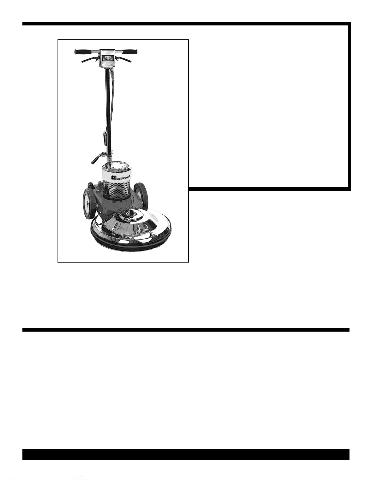
1500 CONTRACTORS
URNISHER
B
SAFETY,
PERATION &
O
AINTENANCE
M
MANUAL
/PARTS LIST
W
This unit is intended for commercial use.
READ & FOLLOW ALL INSTRUCTIONS,
WARNINGS & CAUTIONS
BEFORE USING THIS BURNISHER
This burnisher will afford you many years of
trouble free operating satisfaction if it is
given proper care. All parts have passed
rigid quality control standards before being
assembled to produce the finished product.
Prior to packaging, the units again inspected for assurance of flawless assembly.
Your burnisher was protectively packed to
prevent damage in shipment. We recommend that upon delivery, remove the unit
from its carton and carefully inspect it for
any possible damage in transit.
If damage is discovered, immediately notify
the transportation company that delivered
your burnisher. As a shipper, we are
unable to act upon any claim for concealed
damage. You must originate any claim
within 5 days of delivery.
These instructions are for your protection
and information. PLEASE READ CAREFUL-
LY ! Failure to follow these precautions could
result in injury or discomfort.
SAVE THESE INSTRUCTIONS
PAGE 1
Contractor Burnisher Manual - PN 408794 - Printed in USA 11/20/06
READ ALL
NSTRUCTIONS
I
BEFORE
OPERATING
IMPORTANT
SAFETY
INSTRUCTIONS
WARNING:
To reduce the risk of fire, electric shock or injury:
When using an electric burnisher, basic precautions should
always be following, including the following:
1) DO NOT leave burnisher plugged in
when not in use. Unplug from outlet
when not in use and before servicing.
2) Electric shock could occur if exposed
to rain. Store indoors.
3) This is NOT a toy. Close attention is
necessary when used around or near
children.
4) Use only as described in this manual.
Use only manufacturer's recommended
attachments.
5) DO NOT use with damaged cord
plug. When burnisher is not working as
it should because it has been dropped,
damaged, left outdoors, or dropped into
water, contact the manufacturer or
authorized service center.
GROUNDING
SAFETY
6) DO NOT pull or carry by the cord, use
power cord as a handle, close a door on
cord, or pull cord around sharp edges
or corners. DO NOT run burnisher over
cord. Keep cord away from heated surfaces.
7) DO NOT handle the burnisher plug
with wet hands.
8) DO NOT unplug by pulling on the
cord. To unplug, grasp the plug, not the
power cord.
9) DO NOT put any objects into motor
openings.
10) Keep hair, loose clothing, fingers
and all parts of body away from moving
parts.
11) DO NOT operate where oxygen or
anesthetics are used.
12) DO NOT use around flammable or
combustible liquids such as gasoline or
use in areas where they may be present.
13) DO NOT use an extension cord
unless absolutely necessary. If an extension cord is used, then wire size must
be #14 gauge or thicker and should not
exceed 50 feet in length. Extension cord
must be three-wire type to insure
grounding protection.
14) Replace damaged or worn parts
immediately with genuine original equipment parts to maintain safety and to
protect your limited warranty.
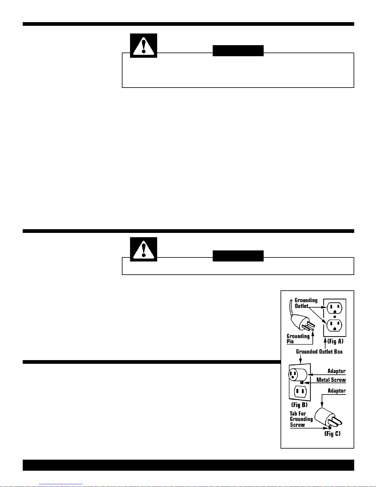
DANGER:
Improper use of the grounding plug can result in a risk of electric shock.
INSTRUCTIONS
This burnisher must be grounded. If it should
malfunction or breakdown, grounding provides
a path of least resistance for electrical current
to reduce the risk of electric shock. The burnisher is equipped with a cord having an equipment-grounded plug. The plug must be inserted into an appropriate outlet that is properly
installed and grounded in accordance with all
local codes and ordinances
GROUNDING METHODS
This burnisher is for use on a nominal 120 volt
circuit, and has a grounding plug that looks like
the plug illustrated in (Fig A). A temporary
adaptor that looks like the adaptor illustrated in
(Fig B & C) may be used to connect the plug to
a 2-pole receptacle as shown in (Fig A) if a
properly grounded outlet is not available.
If repair or replacement of the cord or plug is
necessary, DO NOT connect the grounding
wire to either flat blade terminal. The wire with
insulation having an outer surface that is green
with or without yellow stripes is the grounding
wire.
The temporary adaptor should be used only until
a properly grounded outlet (Fig A)can be
installed by a qualified electrician. The green
color rigid ear, lug, or the like extending from
the adaptor must be connected to a permanent
ground such as a properly grounded outlet box
cover. Whenever the adaptor is used, it must
be held in place by the metal screw (Fig C).
PAGE 2
WARNING:
Improper connection of the equipment-grounding conductor can result in a risk of
electrical shock. Check with a qualified electrician or service person if you are in
doubt as to whether the outlet is properly grounded.
DO NOT modify the plug provided with the burnisher. If it will not fit the
outlet, have a proper outlet installed by a qualified electrician.
NOTE:
In Canada, the use of a temporary adaptor is not permitted
by the Canadian Electrical Code.
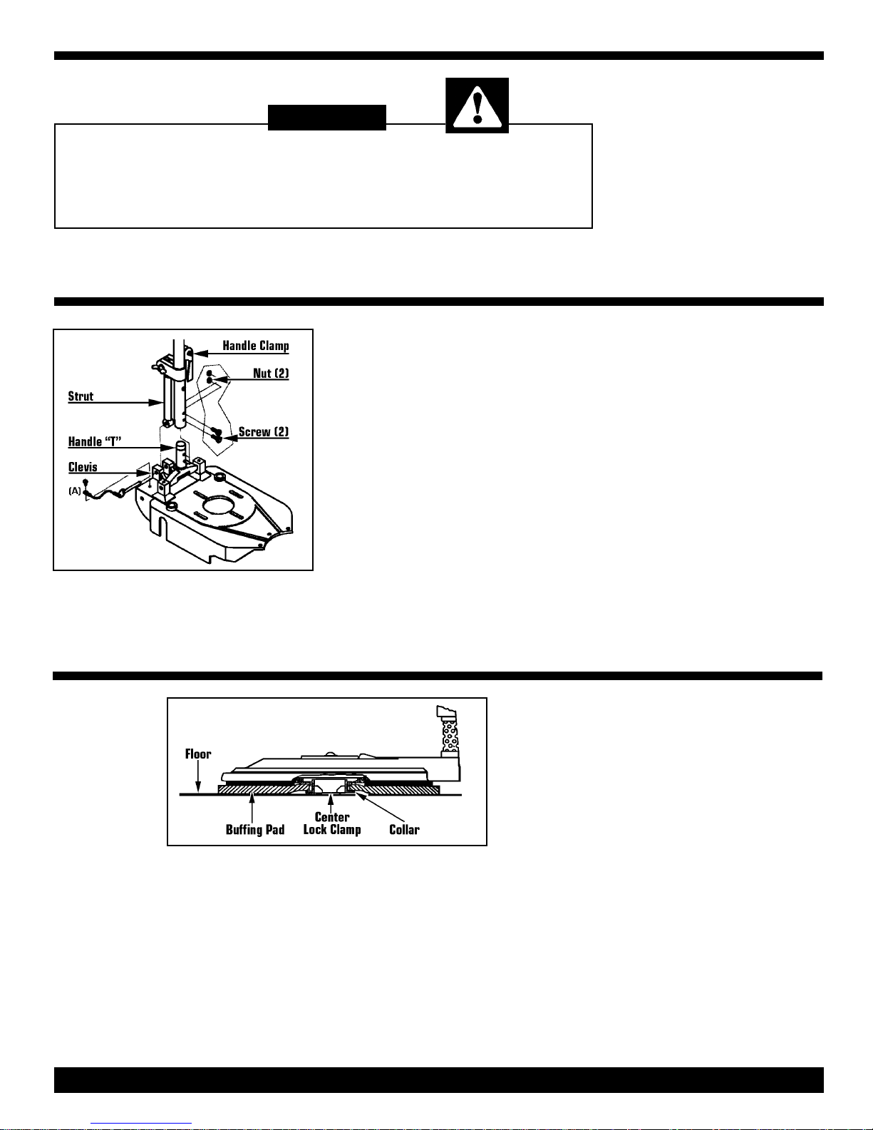
To Attach Handle
1) Remove burnisher chassis and handle
assembly for the carton.
2) Using screws #353272 and nuts
#354791, insert one screw into each hole
and secure with nuts on opposite side of
handle tube. DO NOT over-tighten nuts,
this will deform the handle tube.
3) Slide the handle assembly over handle
"T" on the chassis making sure the line
cord is towards back of burnisher and
loosen handle clamp.
This burnishers is shipped without the handle attached to the chassis. The hardware
kit (#372811) contains the necessary
parts to attach the handle to the burnisher.
4) Remove speed- pin (A) from clevis. Line
up strut with clevis and insert speed-pin (A)
thru clevis and strut.
HANDLE
ASSEMBLY
INSTRUCTIONS
The floor pad packed with this burnisher
MUST BE attached to pad driver before
operating the unit.
To Install Pad:
1) Remove center cut-out from floor pad
2) Tilt burnisher back on the rear wheel and
unscrew center lock clamp pad retainer by
turning counterclockwise in "OPEN" posi-
tion.
FLOOR PAD
INSTALLATION
3) Center pad on center lock clamp or collar with hair side down for optimum finish.
4) Secure pad to pad driver by turning center lock clamp clockwise in the "CLOSE"
position until it is locked in position.
DO NOT OPERATE the pad driver without
the pad securely in place to avoid damage
to the floor and/or burnisher.
PAGE 3
 Loading...