

Page 1
Owner's Manual
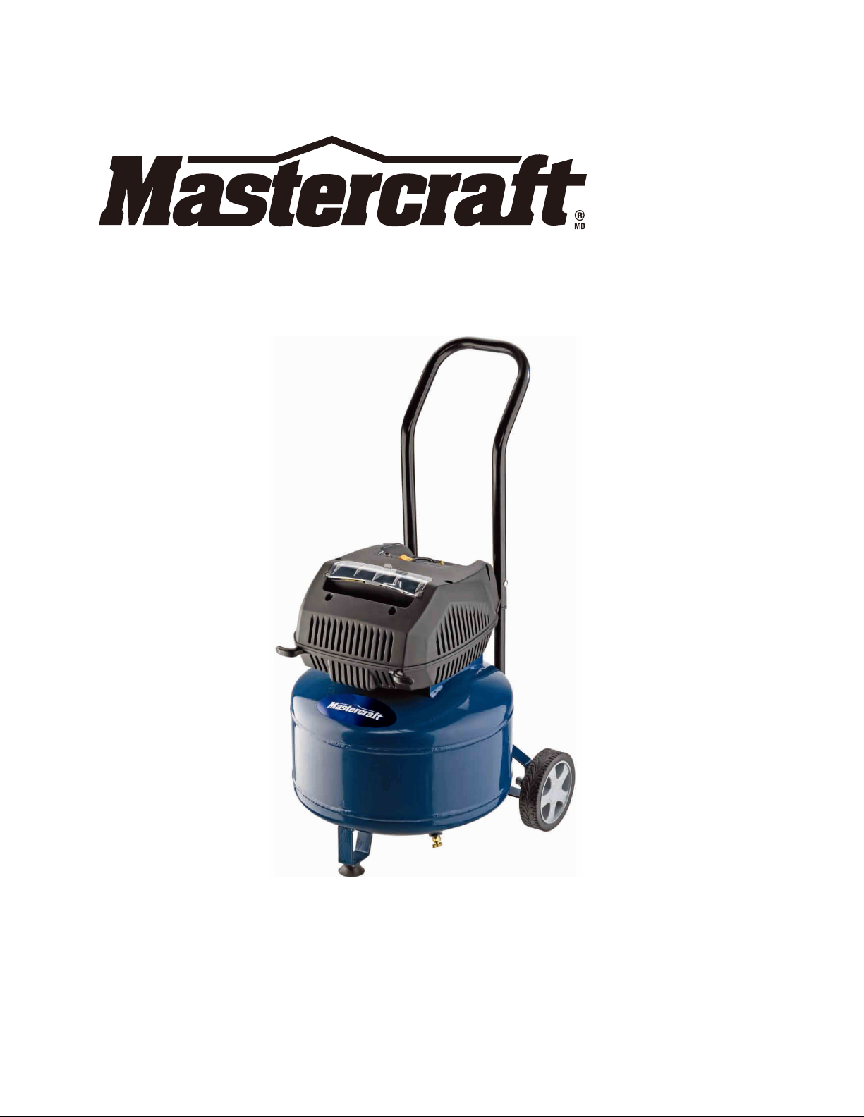
8 GALLON AIR COMPRESSOR
099-4119-2
TOLL FREE HELPLINE: 1-877-888-3872
CAUTION : Before using this tool or any of its accessories, read this manual and follow
all Safety Rules and Operating Instructions.
Imported by Mastercraft Canada, Toronto, Canada M4S 2B8
Page 2

TABLE OF CONTENTS
SPECIFICATIONS.............................................................................................
SAFETY GUIDELINES .....................................................................................
IMPORTANT SAFETY INSTRUCTIONS ..........................................................
GENERAL SAFETY RULES........................................................................
SPECIFIC SAFETY RULES............................................................................
GLOSSARY OF TERMS.................................................................................
ACCESSORIES INCLUDED.................................................................................
ASSEMBLY.................................................................................................14-22
MAINTENANCE ........................................................................................
STORAGE ......................................................................................................
TROUBLESHOOTING................................................................................
LIMITED WARRANTY .............................
EXPLODED VIEW/PARTS LIST................................................................
.......................................................
2
3
3
9-10
11
12
13
22-23
23
24-26
27
28-29
SPECIFICATIONS
Peak horsepower.............................................................................................. 2
Tank Size..............................................................................................8 gallons
Air delivery (SCFM) @ 40 PSI.......................................................................4.0
Air delivery (SCFM) @ 90 PSI.......................................................................3.4
Maximum pressure (PSI)..............................................................................125
Pump design............................................................Aluminum cylinder; oil-less
Power................................................................................120 V, 60 Hz, 13.5 A
Weight..........................................................................................50.7 lb (23 kg)
2
Page 3
SAFETY GUIDELINES
This manual contains information that is important for you to know andunderstand. This
information relates to protecting YOUR SAFETY and PREVENTING EQUIPMENT
PROBLEMS. To help you recognize thisinformation, we use the symbols below. Please
read the manual and payattention to these symbols.
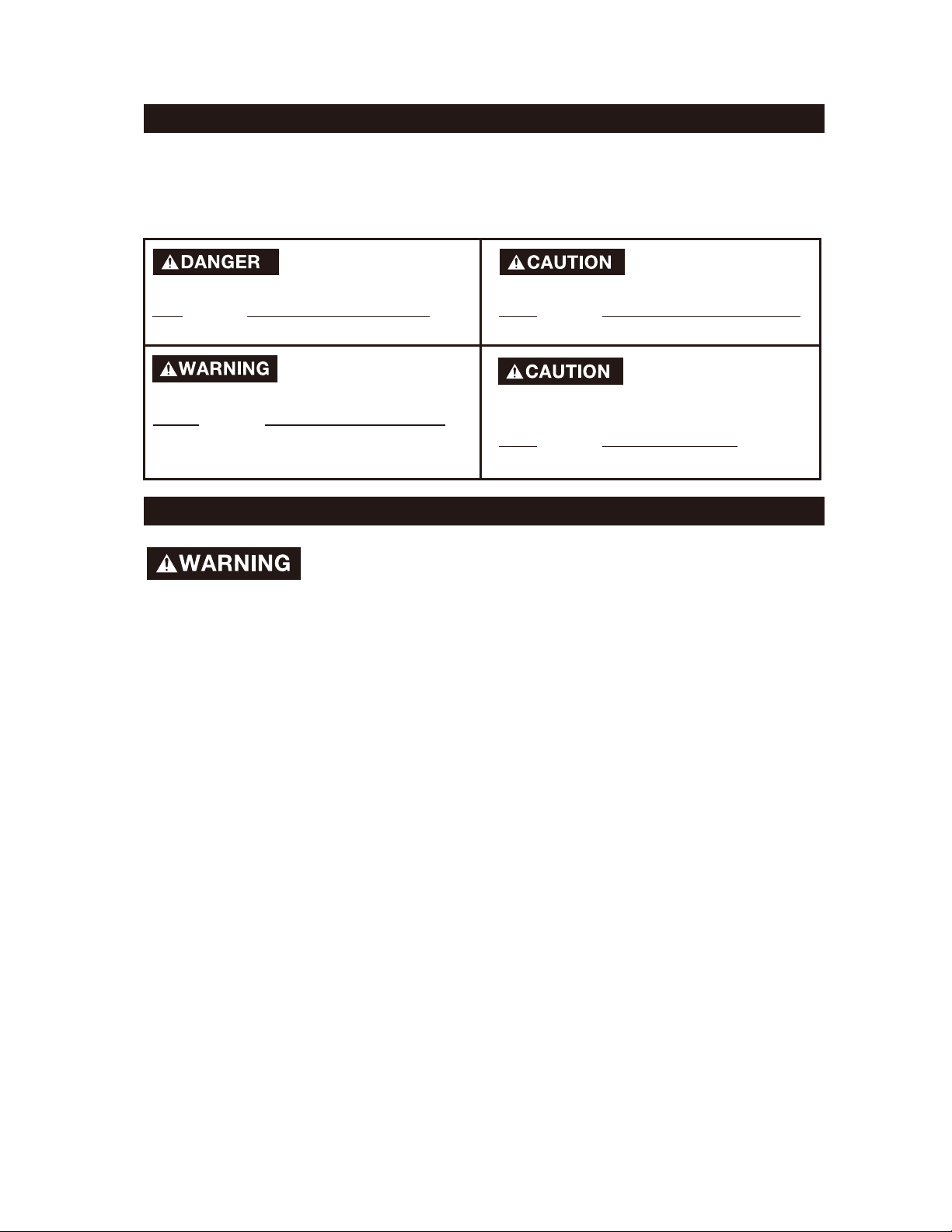
- DEFINITIONS
Indicates animminently
hazardoussituation which, if not avoided,
will result in death or serious injury.
Indicates apotentially
hazardoussituation which, if not avoided,
may result in minor or moderate injury.
Indicates a potentially
hazardous situation which, if not avoided,
could result in death or serious injury.
Used without thesafety
alert symbol, indicates a potentially
hazardous situation which, if not avoided,
may result in property damage.
IMPORTANT SAFETY INSTRUCTIONS
Some dust created by power sanding, sawing, grinding, drilling, and
other construction activities contains chemicals that are known to cause cancer, birth defects
or other reproductive harm. Some example of these chemicals are:
• lead from lead-based paints
• crystalline silica from bricks and cement and other masonry products
• arsenic and chromium from chemically-treated lumber
Your risk of exposures to these chemicals varies, depending on how often you do this type
of work. To reduce your exposure to these chemicals, work in a well-ventilated area, work
with approved safety equipment, and always wear a approved, properly fitting face mask or
respirator when using such tools.
When using air tools, basic safety precautions should always be followed toreduce the risk of
personalinjury.
3
Page 4
IMPORTANT SAFETY INSTRUCTIONS
Save these instructions
Improper operation or maintenance of this product could result in serious injury andproperty
damage. Read and understand all warnings and operating instructions before using this
equipment.
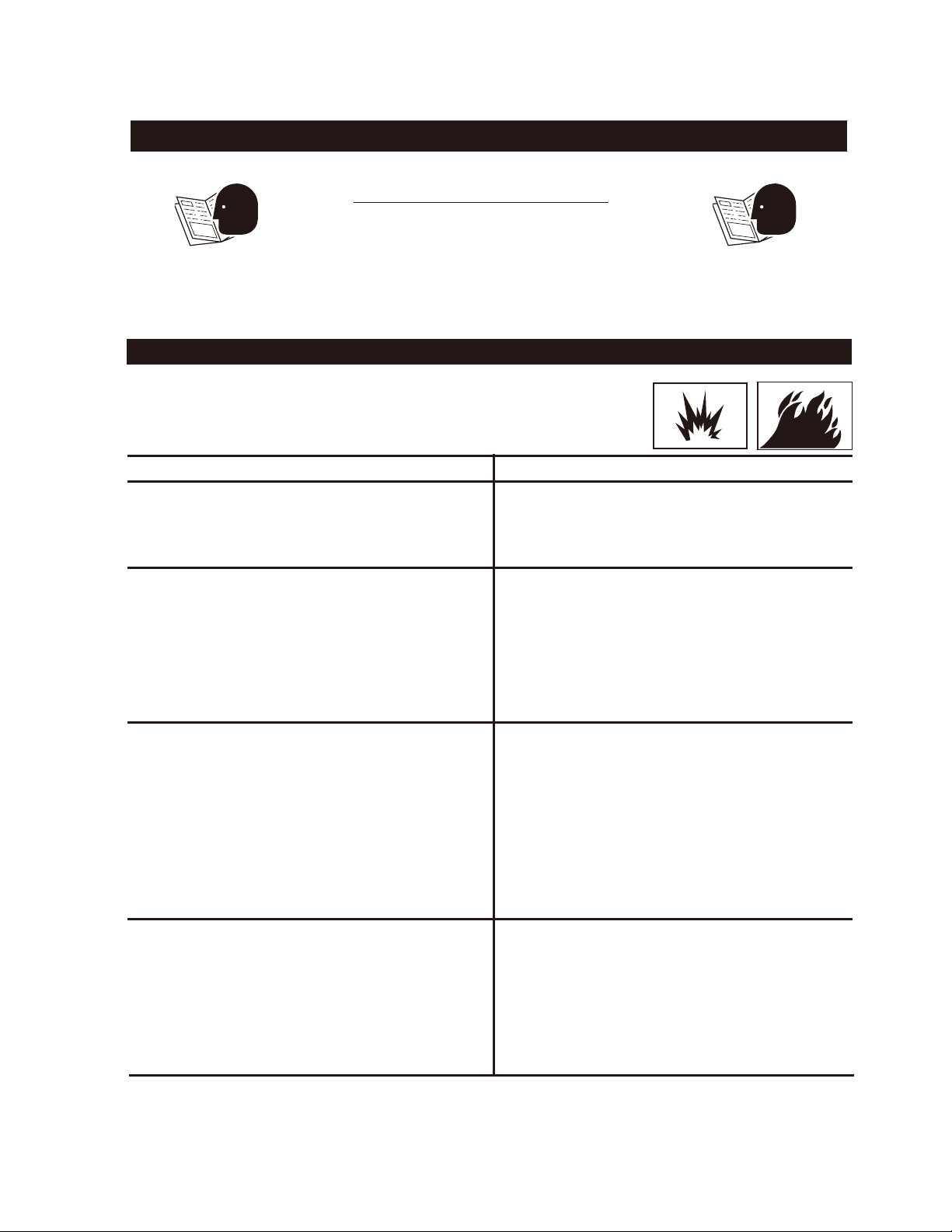
HAZARD
WARNING: Risk of explosion or fire
What Could Happen
It is normal for electrical contacts within
the motor and pressure switch to spark.
If electrical sparks from the compressor
come into contact with flammable vapors,
they may ignite, causing fire or explosion.
Restricting any of the compressor's
ventilation openings will cause serious
overheating, and could cause fire.
How To Prevent It
Always operate the compressor in a
well-ventilated area free of combustible
materials, gasoline, or solvent vapors.
If spraying flammable materials, locate the
compressor at least 20' (6 m) away from
the spraying area. An additional length of
hose may be required.
Store flammable materials in a secure
location away from the compressor.
Never place objects against or on top of
the compressor. Operate the compressor
in an open area at least 12" (30 cm) away
from any wall or obstruction that would
restrict the flow of fresh air to the
ventilation openings.
Operate the compressor in a clean, dry,
well-ventilated area.
Unattended operation of this product could
result in personal injury or property
damage. To reduce the risk of fire, do not
allow the compressor to operate
unattended.
Always remain in attendance with the
product while it is operating.
Always disconnect electrical power by
moving the pressure switch lever to the off
position, and drain tank daily or after each
use.
4
Page 5

WARNING: Risk of Bursting
Air Tank: The following conditions could lead to a weakening of the tank, and result
in a violent tank explosion and could cause property damage or serious injury.
What Could Happen
How To Prevent It
1. Failure to properly drain condensed water
from tank, causing rust and thinning of
the steel tank.
2. Modifications or attempted repairs to the
tank.
3. Unauthorized modifications to the
unloader valve, safety valve, or any other
component that controls tank pressure.
4. Excessive vibration can weaken the air
tank and cause a rupture or explosion.
ATTACHMENTS & ACCESSORIES:
Exceeding the pressure rating of air tools,
spray guns, air-operated accessories, tires,
and other inflatables can cause them to
explode or fly apart, and could result in
serious injury.
Drain tank daily or after each use. If tank
develops a leak, replace it immediately with
a new tank or replace the entire compressor.
Never drill into, weld, or make any
modifications to the tank or its attachments.
The tank is designed to withstand specific
operating pressures. Never make
adjustments or parts substitutions to alter
the factory-set operating pressures.
For essential control of air pressure, you
must install a pressure regulator and
pressure gauge to the air outlet (if not
equipped) of your compressor. Follow the
equipment manufacturer's recommendations, and never exceed the maximum
allowable pressure rating of attachments.
Never use the compressor to inflate small,
low-pressure objects such as children’s toys,
footballs, basketballs, etc.
WARNING: Risk from Flying Objects
What Could Happen
The compressed air stream can cause soft
tissue damage to exposed skin, and can
propel dirt, chips, loose particles,
and small objects at high speed, resulting in
property damage or personal injury.
How To Prevent It
Always wear ANSI Z87.1 approved safety
glasses with side shields when using the
compressor.
Never point any nozzle or sprayer toward
any part of the body or at other people or
animals.
Always turn the compressor off and bleed
pressure from the air hose and tank before
attempting maintenance or attaching tools
or accessories.
5
Page 6
HAZARD
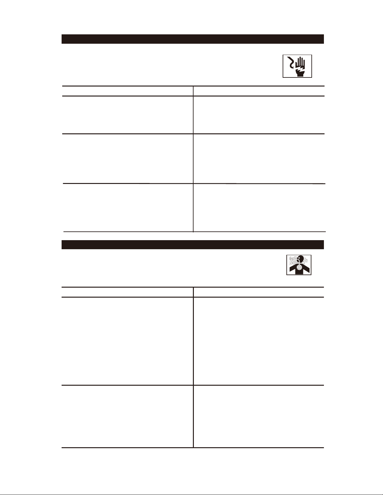
WARNING: Risk of Electric Shock
What Could Happen
Your air compressor is powered by
electricity. Like any other electrically
powered device, it may cause electric
shock if it is not used properly.
Repairs attempted by unqualified
personnel can result in serious injury or
death by electrocution.
Electrical Grounding: Failure to provide
adequate grounding for this product
could result in serious injury or death
from electrocution.
See grounding instructions.
WARNING: Risk to Breathing
How To Prevent It
Never operate the compressor outdoors
when it is raining or in wet conditions.
Never operate the compressor with
missing or damaged protective covers.
Any electrical wiring or repairs required on
this product should be performed by
authorized service centre personnel in
accordance with national and local
electrical codes.
Make certain that the electrical circuit
to which the compressor is connected
provides proper electrical grounding,
correct voltage and adequate fuse
protection.
HAZARD
What Could Happen
The compressed air directly from your
compressor is not safe for breathing.
The air stream may contain carbon
monoxide, toxic vapors, or solid particles
from the tank. Breathing these contaminants can cause serious injury or death.
Sprayed materials such as paint, paint
solvents, paint remover, insecticides, and
weed killers, may contain harmful vapors
and poisons.
How To Prevent It
Air obtained directly from the compressor
should never be used to supply air for
human consumption. In order to use air
produced by this compressor for breathing,
suitable filters and in-line safety equipment
must be properly installed. In-line filters
and safety equipment used in conjunction
with the compressor must be capable of
treating air to all applicable local and
federal codes prior to human consumption.
Work in an area with good crossventilation Read and follow the safety
instructions provided on the label or safety
data sheets for the materials you are
spraying. Use approved respirator that is
designed for use with your specific
application.
6
Page 7
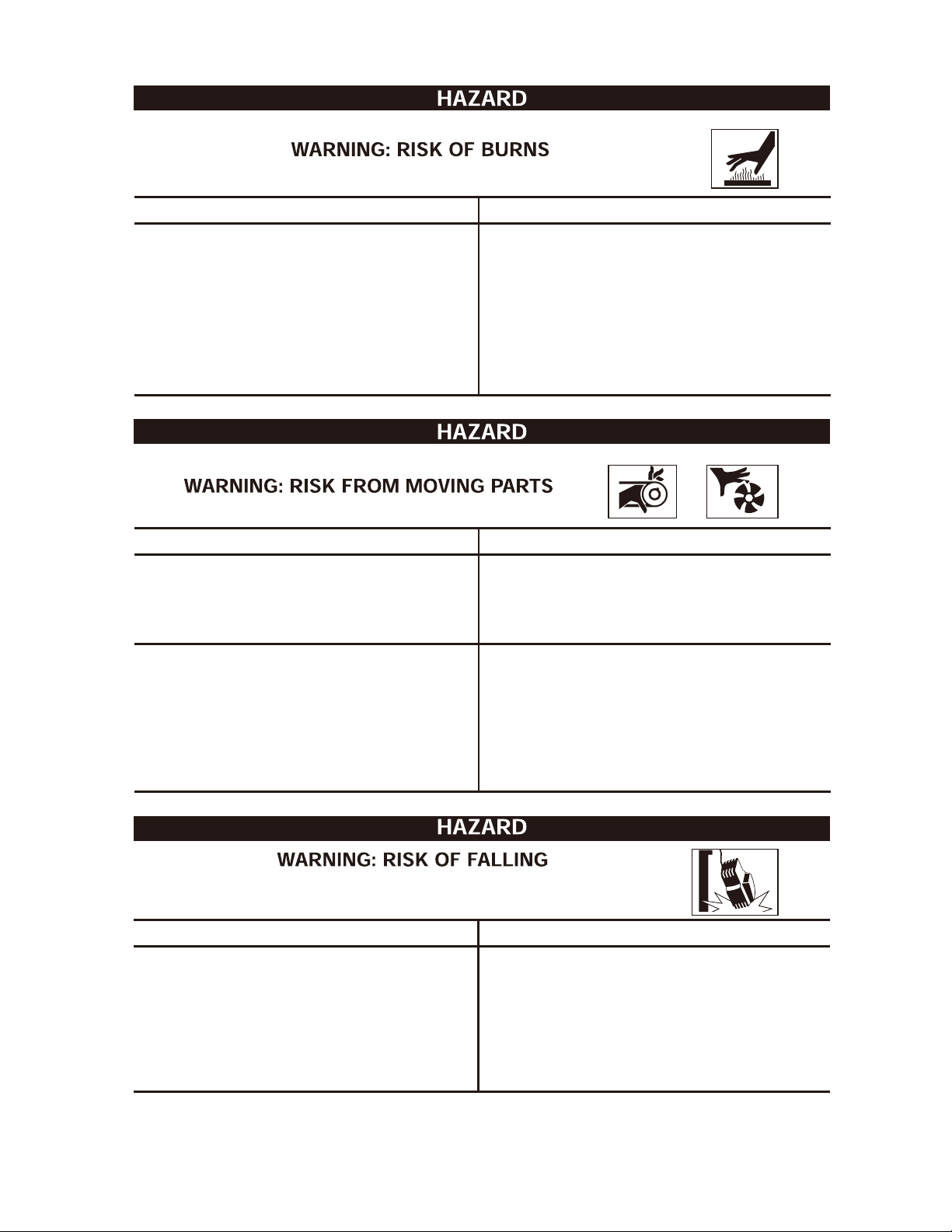
What Could Happen
Touching exposed metal such as the
compressor head or outlet tubes can
result in serious burns.
What Could Happen
Moving parts such as the pulley, flywheel,
and belt can cause serious injury if they
come into contact with you or your clothing.
How To Prevent It
Never touch any exposed metal parts
on the compressor during or immediately
after operation. Compressor will remain
hot for several minutes after operation.
Do not reach around protective shrouds or
attempt maintenance until unit has been
allowed to cool.
How To Prevent It
Never operate the compressor with
missing or damaged guards or covers.
Attempting to operate the compressor
with damaged or missing parts, or
attempting to repair the compressor with
protective shrouds removed can expose
you to moving parts, and can result in
serious injury.
What Could Happen
A portable compressor can fall from a
table, workbench, or roof, causing
damage to the compressor and/or
serious injury or death.
Any repairs required on this product
should be performed by authorized
service centre personnel.
How To Prevent It
Always operate the compressor in a
stable secure position to prevent
accidental movement of the unit. Never
operate the compressor on a roof or
other elevated position. Use additional
air hoses to reach high locations.
7
Page 8
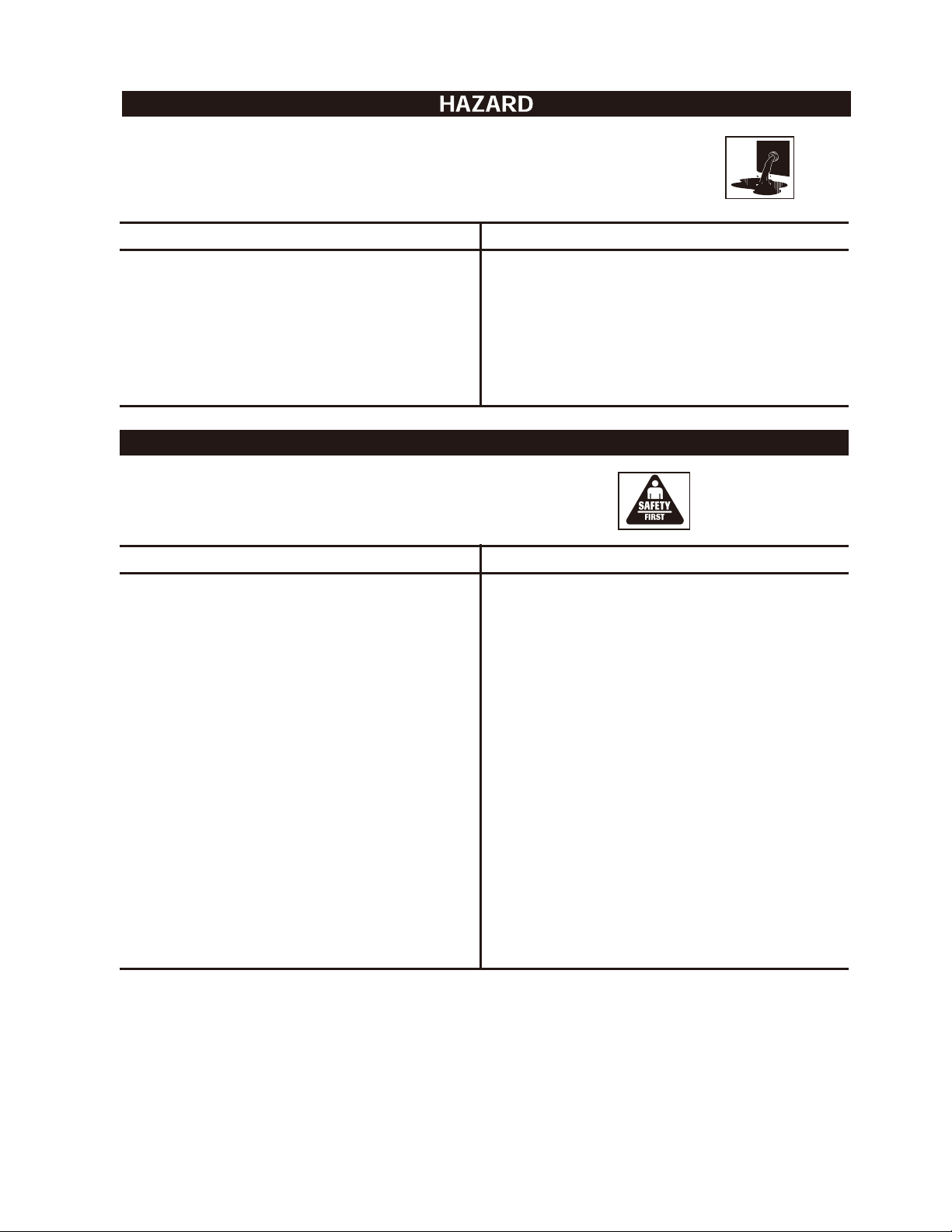
WARNING: RISK OF SERIOUS INJURY OR PROPERTY
DAMAGE WHEN TRANSPORTING COMPRESSOR
(Fire, Inhalation, Damage to Vehicle Surfaces)
What Could Happen
Oil can leak or spill, which could cause a
fire or breathing hazard resulting in
serious injury or death. Oil leaks will
damage carpet, paint or other surfaces in
vehicles or trailers.
HAZARD
WARNING: RISK OF UNSAFE OPERATION
What Could Happen
Unsafe operationof your air compressor
could lead to serious injury or death toyou
or others.
How To Prevent It
Always place the COMPRESSOR on a
protective mat when transporting in order
to protect against damage to vehicle
from leaks. Remove the COMPRESSOR
from the vehicle immediately upon arrival
at your destination.
How To Prevent It
Review and understand all instructions
and warnings in this manual.
Become familiar with the operation
andcontrolsof the air compressor.
Keep operating area clearof all persons,
pets, and obstacles.
Keep children away from the air compressor at all times.
Do not operate the product when fatigued
or under the influence of alcohol or drugs.
Stay alert at all times.
Never defeat the safety features of this
product.
Equip area of operation with a fire
extinguisher.
Do not operate machine with missing,
broken, or unauthorized parts.
8
Page 9

GENERAL SAFETY RULES
WORK AREA
Keep your work area clean and well lit. Cluttered benches and dark areas invite
accidents.
Do not operate power tools in an explosive atmosphere, such as in the presence of
flammable liquids, gases, or dust. Power tools create sparks that may ignite dust or
fumes.
Keep bystanders, children, and visitors away while operating a power tool.
Distractions can cause you to lose control. Protect others in the work area from debris
such as chips and sparks. Provide barriers or shields as needed.
ELECTRICAL SAFETY
Grounded tools must be plugged into a properly installed and grounded outlet in
accordance with all applicable codes and ordinances. Never remove the grounding prong or modify the plug in any way. Do not use adaptor plugs. Check with a
qualified electrician if you are in doubt as to whether the outlet is properly
grounded. If the tool should electrically malfunction or break down, grounding provides
a low-resistance path to carry electricity away from the user.
Double insulated tools are equipped with a polarized plug (one blade is wider than
the other). This plug will only fit into a polarized outlet one way. If the plug does
not fit fully into the outlet, reverse the plug. If it still does not fit, contact a
qualified electrician to install a polarized outlet. Do not change the plug in any
way. Double insulation eliminates the need for the three-wire grounded power cord
and grounded power supply system.
Avoid body contact with grounded surfaces such as pipes, radiators, ranges, and
refrigerators. There is an increased risk of electric shock if your body is grounded.
Do not expose power tools to rain or wet conditions. Water entering a power tool will
increase the risk of electric shock.
Do not abuse the power cord. Never use the power cord to carry the tool or pull
the plug from an outlet. Keep the power cord away from heat, oil, sharp edges, or
moving parts. Replace damaged power cords immediately. Damaged power cords
increase the risk of electric shock.
When operating a power tool outside, use an outdoor extension cord marked
“W-A” or “W”. These extension cords are rated for outdoor use, and reduce the risk of
electric shock.
PERSONAL SAFETY
Stay alert. Watch what you are doing, and use common sense when operating a
power tool. Do not use a power tool while tired or under the influence of drugs,
alcohol, or medication. A moment of inattention while operating a power tool may
result in serious personal injury.
Dress properly. Do not wear loose clothing or jewellery. Contain long hair.
Keep your hair, clothing, and gloves away from moving parts. Loose clothes,
jewellery, or long hair can get caught in moving parts.
9
Page 10

GENERAL SAFETY RULES
Avoid accidental start-ups. be sure the power switch is off before plugging in the
tool. Carrying a power tool with your finger on the power switch or plugging in a power
tool with the power switch on invites accidents.
Remove adjusting keys or wrenches before turning the power tool on. A wrench or
a key that is left attached to a rotating part of the power tool may result in personal
injury.
Do not overreach. Keep proper footing and balance at all times. Proper footing and
balance enables better control of the power tool in unexpected situations.
Use safety equipment. Always wear eye protection. A dust mask, non-skid safety
shoes, a hard hat, and hearing protection must be used for appropriate conditions. Always
wear ANSI-approved safety goggles and a dust mask/respirator when using or performing
maintenance on this tool.
CAUTION Risk of Bursting – Tilt tank to drain.
TOOL USE AND CARE
Use clamps (not included) or other practical ways to secure and support the
workpiece to a stable platform. Holding the work by hand or against your body is
unstable, and may lead to loss of control.
Do not force the tool. Use the correct tool for your application. The correct tool will
do the job better and safer at the rate for which it is designed. Do not force the tool, and
do not use the tool for a purpose for which it is not intended.
Do not use the power tool if the power switch does not turn it on or off. Any tool that
cannot be controlled with the power switch is dangerous, and must be replaced.
Disconnect the power cord plug from the power source before making any
adjustments, changing accessories, or storing the tool. Such preventive safety
measures reduce the risk of starting the tool accidentally.
Store idle tools out of reach of children and other untrained persons. Tools are
dangerous in the hands of untrained users. Keep children away from power tools.
Maintain tools with care. Properly maintained tools are less likely to bind, and are easier
to control. Do not use a damaged tool. Tag damaged tools “Do not use” until repaired.
Check for misalignment or binding of moving parts, broken parts, and any other
condition that may affect the tool’s operation. If damaged, have the tool serviced
before using. Many accidents are caused by poorly maintained tools.
Use only accessories that are recommended for your model by the manufacturer.
Accessories that may be suitable for one tool may become hazardous when used on
another tool.
SERVICE
Tool servicing must be performed only by qualified repair personnel. Service or
maintenance performed by unqualified personnel could result in a risk of injury.
10
Page 11

SPECIFIC SAFETY RULES
Maintain labels and nameplates on the Air Compressor. They carry important
information. If unreadable or missing, contact the Toll-free Helpline,
at 1-877-888-3872 for a replacement.
Always wear ANSI-approved safety impact eye goggles and heavy work gloves
when using the Air Compressor. Using personal safety devices reduces the risk of
injury.
Maintain a safe working environment. Keep the work area well lit. Make sure there is
adequate surrounding workspace. Always keep the work area free of obstructions,
grease, oil, trash, and other debris. Do not use a power tool in areas near flammable
chemicals, dusts, and vapors. Do not use this product in a damp or wet location.
Avoid unintentional starting. Make sure you are prepared to begin work before turning
on the Air Compressor.
Do not force the Air Compresso
pressure and capacity for which it was designed.
Always unplug the Air Compressor from its electrical outlet before performing
any inspection, maintenance, or cleaning procedures.
Before each use, check all nuts, bolts, and screws for tightness. Vibration may
cause these to loosen.
Drain the compressor every da
sor.
r. This tool will do the work better and safer a the
y.
Do not allow moisture to build up inside the compres-
Make sure all equipment is rated to the appropriate capacity.
air pressure to the tool
Avoid explosions and fire. Never place flammable objects near the compressor.
Never spray water or any flammable liquids toward the compressor.
Avoid bodily injury. Never direct the air outlet at persons or animals.
Never leave the air tool unattended when it is plugged into the air compressor.
Turn off the tool and unplug it from the air compressor outlet before leaving.
WARNING! People with pacemakers should consult their physician(s) before using
this product. Electromagnetic fields in close proximity to a heart pacemaker could
cause interference to or failure of the pacemaker.
’s operating capacity.
Adjust the output
11
Page 12

GLOSSARY OF TERMS
Become familiar with these terms before operating the unit.
CFM: Cubic feet per minute.
SCFM: Standard cubic feet per minute; a unit of measure of air delivery.
PSI: Pounds per square inch ; a unit of measure of pressure.
Cut-In Pressure: While the motor is off, air tank pressure drops as you continue to use
your accessory. When the tank pressure drops to a certain level, the motor will restart
automatically. The pressure at which the motor automatically restarts is called "cut-in"
pressure.
Cut-Out Pressure: When an air compressor is turned on and begins to run, air pressure in
the air tank begins to build. It builds to a certain pressure before the motor automatically
shuts off - protecting your air tank from pressure higher than its capacity. The pressure at
which the motor shuts off is called "cut-out" pressure.
Branch Circuit: Circuit carrying electricity from the electrical panel to the outlet.
DUTY CYCLE
Air compressors should be operated on not more than a 50% duty cycle. This means that
forcing an air compressor to pump air more than 50% of one hour is considered misuse,
because the air compressor is undersized for the required air demand. Maximum compressor
pumping time is 30 minutes per hour.
12
Page 13

ACCESSORIES INCLUDED
The unit is supplied with an accessory kit and inflator/deflator kit. Choose the accessory needed.
A-1
A-10
A-2
A-7
A-3
A-4
ITEM
A-1
A-2
A-3
A-4
A-5
A-6
A-7
A-8
A-9
A-10
A-
11
A-5
A-6
A-8 A-9
NAME
Recoil air hose
Inflation needle
Rubber inflation nozzle
Tapered inflation nozzle
Blow gun adaptor fitting
Blow gun safety nozzle
Blow gun
Tire chuck
¼” Quick-connect male plugs
Sealing tape
¼” Quick-connect female plug
A-12
A-11
AMOUNT MODEL NUM.
1 3790175
1
1
1
1
1
1
1
1
1
1
37902110
37906110
37904110
37911110
37907110
37905110
37903110
37909110
37901110
37912110
A-12
1/4” Female quick-connect body
13
1
37903124
Page 14

ASSEMBLY
Accessories
The unit is supplied with an accessory kit and inflator/deflator kit. Choose the accessory
needed.
Installing Accessories
Installing the Tire Chuck
1. Attach the tire chuck (a) to the hose (b), and tighten securely using wrenches.
Installing Accessories
1. Attach the blow gun (c) to the hose (b).
2. Attach the safety nozzle (d) or the blow gun adaptor (e) to the blow gun.
NOTE: To use the inflation needle (f) or the tapered inflation nozzle (g), the blow gun adaptor
(e) must be attached to the blow gun.
3. Attach the inflation needle (f) to the blow gun adaptor on the blow gun.
g
(See Fig. A)
a
e
b
f
c
d
Fig. A
14
Page 15

ASSEMBLY
Installing the Inflation Needle or the Tapered Inflation Nozzle
The blow gun (c) and blow gun adaptor (e) from the accessory kit are required in order to use
the inflator/deflator kit. (See Fig. B/Fig. C)
1. Attach the blow gun to the hose.
2. Attach the blow gun adaptor to the blow gun.
3. Attach the inflation needle (f) or the tapered inflation nozzle (g).
Safety Nozzle
g
f
e
B
Fig.
c
15
Fig.
C
Page 16

ASSEMBLY
Quick-Connect (See Fig. D)
1. Assemble the 1/4”male quick-connect plug (k,l) or 1/4” female quick-connect
plug to the 1/4” Female quick-connect body.
2. Attach the quick-connect plug to the hose.
j
i
PULL
k
l
Fig. D
NOTE: Always use PTFE tape on all threaded components, to prevent leaks.
16
Page 17

ASSEMBLY
Precautions
Drain the moisture from the tank daily to help prevent corrosion.
Pull the pressure relief valve ring daily to ensure proper function and clear possible obstructions.
To provide proper ventilation for cooling, the compressor must be kept at least 12” (31 cm) from
the nearest wall, in a well-ventilated area.
Fasten the compressor securely and release tank pressure before transporting.
Protect the air hose and electric cord from damage and puncture. Inspect them weekly for weak or
worn spots, and replace if necessary.
To reduce the risk of electric shock, do not expose to rain. Store indoors.
Never operate the compressor if the pow er cord or plug is damaged. Take the
equipment to the nearest Authorized Service Center, to have it replaced.
Basic Air Compressor Components
Oil-less air compressors are factory lubricated for life and do not
require any further lubricated.
The basic components of the air compressor are the electric motor,
pump, pressure switch, and tank. The electric motor (A) powers the
pump. The electric motor is equipped with an overload protector and
an automatic reset. If the motor becomes overheated, the overload
protector will shut it down to prevent damage to the motor. When the
motor cools sufficiently, it will automatically restart.
The pump (B) compresses the air and discharges it into the tank.
The tank (C) stores the compressed air.
The pressure switch (D) shuts down the motor and relieves air
pressure in the pump and transfer tub when the air pressure in the tank
reaches the kick-out pressure. As compressed air is used and the
pressure level in the tank drops to the kick-in pressure, the pressure switch restarts the motor
automatically, without warning, and the pump resumes compressing air.
Assembling the Compressor
1 . Unpack the air compressor. Inspect the unit for damage. If the unit has been
damaged in transit, contact the carrier and complete a damage claim. Do this
immediately as there is a time limit to damage claims.
A & B
D
C
Fig. E
2 . Tighten the handle into its position with the screws included.
3 . Check the compressor’s specifications label to ensure that you have received the model ordered,
and that it has the required pressure rating for its intended use.
4 . Locate the compressor according to the following guidelines:
a . Position the compressor near a grounded electrical outlet (see GROUNDING INSTRUCTIONS,
above).
The compressor must be at least 12”(31 cm) from any wall or obstruction, in a clean,
b .
well-ventilated area, to ensure sufficient air flow and cooling.
17
Page 18

ASSEMBLY
Mini Die Grinder
!
Disconnect air tool from air supply before changing attachments orserious injury could occur.
WARNING
1.Insert stem of grinder attachmentinto collet opening (See Fig. F). Make sure stem is fully inserted.
2.Securely tighten collet withwrenches (supplied with somemodels) (See Fig. G & H ).
Apply one wrench to the collet nutand the other to the spindle. Turnthe wrench on the collet nut to theright,
simultaneously turning theother wrench in the oppositedirection. Make sure stem does notslip out of position.
CAUTION Do not use in conditions near or below freezing, the moisture in the air line may freeze and prevent
tool operation. Do not store tools in a cold weather environment to prevent frost or ice formation on the tools
operating valves and mechanisms that could cause tool failure. Store in a dry place.
1. Always use proper guard with grinding wheel. A guard reduces the risk of injury to persons from broken wheel
fragments.
2. Accessories must be rated for at least the speed of the tool marked on the tool label. Wheels and other
accessories running over rated speed can fly apart and result in a risk of injury to persons.
!
NOTICE
All air compressors contain maintenance parts that require periodic replacement. These used parts,
including air filters and used lubricating oil, may contain regulated substances that must be disposed of in
accordance with local, state, and federal laws and regulations.
Grinder
Attachment
Fig. F
Fig. H
Collet
Nut
To Tighten
Collet Turn
Wrench To The
Right
Always Turn This
Wrench In The
Opposite
Direction
Specifications
SCFM requirement. . . .3.0 @ 90 PSI
Collet Size . . . . . . . .1/4”
Air Inlet . . . . . . . . . .1/4” NPT
Min. Hose Size . . . . .3/8”
Weight . . . . . . . . . . .11 oz (0.3 kg)
Fig. G - Wrenches
Manufacturing Code
Collet
Air Inlet
Air Exhaust
Mini Die Grinder Features
18
Throttle lever
Page 19

Air-powered Ratchet
ASSEMBLY
Fig. I
B
A
C
D
E
A Square drive
B Forward/reverse switch D Trigger
C Handle E 1/4" Quick-connect male plug
Specifications:
Max Torque: 45ft-lb
Air Inlet: 1/4” NPT
Weight: 2 lb 10 oz (1.2 kg)
Important Information
Compatible Compressors: Guidelines for Proper Use and Operation
Be sure to use the proper air compressor with Mastercraft® air-powered tools. The compressor that
is being used must be able to supply the proper amount of pressure (PSI) to the tool. Verify that the
tool does not require more SCFM (Standard Cubic Feet per Minute) than the compressor can
deliver without running continuously.
General Use
This Mastercraft® Air-powered Ratchet features a light aluminium body and a steel angle head.
Exhaust is discharged to the front, and grips are ergonomically designed. This ratchet is designed
for automotive applications such as removing or replacing radiators and spark plugs, air conditioning system repairs, and water pump repairs. It is compact, and powerful enough to turn bolts in
confined spaces.
Air System
1.Always use clean, dry, regulated compressed air at 90 PSI.
2.Do not exceed the maximum and minimum pressures. Operating the tool at the wrong pressure
(too low or too high) will cause excessive noise or rapid wear.
3.Keep hands and other parts of the body away from the tool's discharge and working areas when
connecting the air supply.
4.It is recommended that a filter-regulator-lubricator be used, and that it be located as close to the
tool as possible (see Fig. I).
5.If a filter-regulator-lubricator is not installed, place up to 6 drops of air tool oil into the NPT
inlet plug before each use.
6.If a filter-regulator-lubricator is installed, keep the air filter clean. A dirty filter will reduce the air
pressure to the tool, which will cause a reduction in power, efficiency, and general performance.
7.For optimal performance, install a quick connector to the tool and a quick coupler on the hose, if
applicable.
8. Verify that all of the connections in the air supply system are sealed in order to prevent air from
leaking.
CAUTION Do not use in conditions near or below freezing, the moisture in the air line may freeze
and prevent tool operation. Do not store tools in a cold weather environment to prevent frost or ice
formation on the tools operating valves and mechanisms that could cause tool failure. Store in a
dry place.
!
NOTICE
All air compressors contain maintenance parts that require periodic replacement. These
used parts, including air filters and used lubricating oil, may contain regulated substances that must
be disposed of in accordance with local, state, and federal laws and regulations.
19
Page 20

ASSEMBLY
Compressor Controls
A
F
C
D
B
E
A. Pressure switch: This switch turns the compressor ON. It can be operated manually, but
when in the ON position, it allows the compress or to start up or shut down automatically, without
warning, on demand. ALWAYS set this switch to OFF
B. Pressure Relief Valve: If the pressure switch does not shut down the motor when the
pressure reaches the preset level, this valve will pop open automatically to prevent
over-pressurization. To operate manually, pull the ring on the valve to relieve air pressure in the
tank.
C. Tank Pressure Gauge: This gauge measures the pressure level of the air stored in the tank.
It is not adjustable by the operator, and does not indicate line pressure.
D. Air Pressure Regulator: This air pressure regulator enables you to adjust line pressure to
the tool you are using.
Fig J
WARNING! NEVER EXCEED THE MAXIMUM WORKING PRESSURE OF THE TOOL.
TURN THE KNOB CLOCKWISE TO INCREASE PRESSURE, AND COUNTER-CLOCKWISE
TO DECREASE PRESSURE.
E. Regulated pressure gauge: This gauge measures the regulated outlet pressure.
F.
Regulated pressure quick connect coupler: This coupler connects to the regulated outlet
pressure. To connect air hose, push coupler in.
To disconnect air hose, pull the coupler collar back.
Electrical Power Requirements
Electrical Wiring
Refer to the air compressor’s specifications label for the unit’s voltage and amperage requirements.
Use a dedicated circuit. For best performance and reliable starting, the air compressor must be
plugged into a dedicated circuit, as close as possible to the fuse box or circuit breaker. The
compressor will use the full capacity of a typical 15 A household circuit. If other devices are on the
same circuit, the compressor may fail to start. Low voltage or an overloaded circuit can result in
sluggish starting that causes the motor overload protection system circuit breaker to trip, especially in
cold conditions.
RESET BUTTON:
Never exceed the maximum or minimum pressure. Pressure that is too low or this compressor is equipped
with a manual reset overload protector which will shut off motor if it becomes overloaded. If overload protector
shuts motor OFF frequently, look for the following causes. Low voltage Lack to proper ventilation/room
temperature too high, Wrong gauge wire or length of extension cord to reset the air compressor:
1. Turn the air compressor off.
2. Unplug air compressor and wait until compressor cools down.
3. Plug the air compressor into an approved outlet.
4. Turn the air compressor on.
5. Press the reset button.
20
Page 21

Note: A circuit breaker is recommended. If the air compressor is connected to a
circuit protected by a fuse, use dual element time delay fuses (Buss Fusetron type “1”
only).
Extension Cord
Note: Avoid use of extension cords.
For optimum performance, plug the compressor power cord directly into a grounded wall socket. Do
not use an extension cord unless absolutely necessary. Instead, use a longer air hose to reach the
area where the air is needed.
If use of an extension cord cannot be avoided, the cord should be no longer than 100’ and be a
minimum wire size of 12 gauge (AWG). Do not use a 16 or 14 gauge extension cord.
Use only a three-pronged extension cord that has a 3-pronged grounding plug, and a 3-slot receptacle
that will accept this plug. Make sure your extension cord is in good condition. An undersized
cord will cause a drop in line voltage, resulting in loss of power and overheating. The smaller
the gauge number, the heavier the cord.
Grounding Instructions
This product should be grounded. In the event of an electrical short circuit or current leakage,
grounding reduces the risk of electric shock by providing a path for the electric current. Consult with an
electrician if necessary.
This product is equipped with a three-pronged grounded power cord and plug. The plug must be
plugged into an outlet that is properly installed and grounded accordance with all local codes and
ordinances. Never modify the plug.
WARNING! IMPROPER INSTALLATION OF THE GROUNDING PLUG
CAN RESULT IN A RISK OF ELECTRIC SHOCK. IF REPAIR OR
REPLACEMENT OF THE CORD OR PLUG IS NECESSARY, DO NOT
CONNECT THE GROUNDING WIRE TO ANY FLAT BLADE TERMINAL. THE
GROUND WIRE IS EITHER GREEN WITH OR WITHOUT YELLOW STRIPES
AND MUST BE CONNECTED TO THE "GROUND" PIN OF THE PLUG.
This product is for use on a nominal 115 V, 15 A circuit. An outlet with a grounding plug must be
used.
Make sure that the product is connected to an outlet with the same configuration as the plug. No
adaptor should be used with this product.
Breaking in the Pump
1. Turn the pressure switch to the OFF position (A, Fig J).
2. Pull the pressure relief valve.
3. Open the regulator valve (D, Fig J). Turning counter-clockwise.
4. Plug in the power cord.
5. Turn the pressure switch to the ON position (C, Fig J). The compressor will start. Allow the
compressor to run for 15 minutes, to break in the internal parts.
CAUTION: AFTER ABOUT 15 MINUTES IF THE UNIT DOES NOT OPERATE
PROPERLY SHUT DOWN IMMEDIATELY AND CONTACT A SERVICE CENTER.
21
Page 22

6. After about 15 minutes, turn the pressure switch to the OFF position.
7. Close the air pressure regulator by turning it clockwise. Turn the pressure
switch to ON. The tank will now fill.
Note: As compressed air is used, the pressure switch will restart the motor automatically.
Note: During the initial break-in cycle, there will be a slight electrical smell as the motor brushes seat.
This is normal for universal motors and will last for about 5 minutes.
Operating Instructions Daily Startup
1 Turn the pressure switch to the OFF position (A, Fig. J).
2 Close the air pressure regulator (D, Fig J). Turn clockwise.
3 Plug in the power cord.
WARNING! HIGH TEMPERATURES ARE GENERATED BY THE ELECTRICAL MOTOR
AND THE PUMP. TO PREVENT BURNS OR OTHER INJURIES, DO NOT TOUCH THE
COMPRESSOR WHILE IT IS RUNNING. ALLOW IT TO COOL BEFORE HANDLING OR
SERVICING. KEEP CHILDREN AWAY FROM THE COMPRESSOR AT ALL TIMES.
4 Turn the pressure switch to the ON position (C, Fig J).
WARNING! WHEN ADJUSTING FROM A HIGHER TO A LOWER PRESSURE, TURN THE
KNOB COUNTER-CLOCKWISE TO REACH THE DESIRED PRESSURE. DO NOT EXCEED
OPERATING PRESSURE OF THE TOOL OR ACCESSORY BEING USED.
5 Adjust the regulator to the working pressure of the tool.
Shutdown
1 Turn the pressure switch to the OFF position (A, Fig J).
2 Unplug the power cord.
3 Reduce pressure in the tank through the outlet hose. You can also pull the relief
valve ring (B, Fig. J) and keep it open to relieve pressure in the tank.
WARNING! ESCAPING AIR AND MOISTURE CAN PROPEL DEBRIS THAT MAY CAUSE
EYE INJURY. WEAR SAFETY GOGGLES WHEN OPENING THE DRAIN VALVE.
4
Tip the compressor (if necessary for your model) so the drain valve is at the
bottom of the tank(s). Then open the drain valve (B, Fig J) to allow moisture to
drain from the tank.
Maintenance
WARNING! TO AVOID PERSONAL INJURY, ALWAYS SHUT OFF AND UNPLUG THE
COMPRESSOR, AND RELIEVE ALL AIR PRESSURE FROM THE SYSTEM BEFORE
PERFORMING ANY SERVICE ON THE AIR COMPRESSOR.
Regular maintenance will ensure trouble free operation. Your electric powered air compressor
represents high quality engineering and construction; however, even high quality machinery
requires periodic maintenance. The items listed below should be inspected on a regular basis.
22
Page 23

Draining the Tank
Relieve the air pressure in the system and open the drain valve on the bottom of the tank to drain.
WARNING! CONDENSATION WILL ACCUMULATE IN THE TANK. TO PREVENT
CORROSION OF THE TANK FROM THE INSIDE, THIS MOISTURE MUS T BE DRAINED AT THE
END OF EVERY WORKDAY. BE SURE TO WEAR PROTECTIVE EYEWEAR.
Note: In cold climates, drain the tank after each use to reduce problems with
freezing of water condensation.
Checking the Relief Valve
Pull the pressure relief valve daily to ensure that it is operating property and to clear the valve of any possible
obstructions.
Testing for Leaks
Check that all connections are tight. A small leak in any of the hoses or pipe connections will
substantially reduce the performance of your air compressor. If you suspect a leak, spray a small
amount of soapy water around the area of the suspected leak with a spray bottle. If bubbles appear,
repair or replace the faulty component. Do not over tighten any connections.
Storage
Before storing the compressor for a prolonged period, use an air blow gun to clean all dust and
debris from the STORAGE compressor. Disconn
relief valve to release all pressure from the tank. Drain all moisture from the tank. Cover the entire
unit to protect it from moisture and dust.
ect the power cord and coil it up. Pull the pressure
Notice
All air compressors contain maintenance parts that require periodic replacement. These used parts,
including air filters and used lubricating oil, may contain regulated substances that must be disposed
of in accordance with local, state, and federal laws and regulations.
Service
Perform the following maintenance at the intervals indicated below:
Operate the pressure relief valve: Daily
Drain tank: Daily
2 3
Page 24

TROUBLESHOOTING
Note: Troubleshooting problems may have similar causes and solutions.
PROBLEM
Low pressure
Not enough air
Compressor
does not stop
Excessive
starting and
stopping while
not in use
- This is normal.
- Compressor not large enough.
- If pressure drops too low, adjust
regulator while using the accessory.
- Check air requirement of accessory.
If it is higher than the CFM and
pressure supplied by the compressor
you need a larger compressor. Most
accessories are rated at 25% of
CFM while running continuously.
- Consult an electrician.
POSSIBLE CAUSE SOLUTION
Tank Pressure Relief valve is open.
Prolonged excessive use of air.
Compressor not large enough.
Restricted check valve.
Tank leaks.
Blown seal(s).
Fittings leak.
Air leaks from regulator, or regulator
does not regulate pressure.
Regulated pressure gauge reading
drops when air accessory is being
used.
- Close valve
- Decrease use
- Check air requirement of accessory.
If it is higher than CFM and pressure
supplied by the compressor, you need
a larger compressor. Most accessories
are rated at 25% of actual CFM while
running continuously.
- Remove and clean or replace.
Hole in air hose, check and replace if
necessary.
- Replace tank immediately.
DO NOT ATTEMPT TO REPAIR.
- Replace any faulty seals.
- Replace worn parts and reassemble
with new seals.
- Check fittings for leaks with soapy
water. Tighten or reseal leaking
fitting(s). DO NOT OVERTIGHTEN.
- Replace worn parts and reassemble
with new seals. Replace any faulty
seals.
- Dirty or damaged regulator internal
parts.
actual
24
Page 25

Circuit breaker/
fuse trips. Often
Overheating
Motor Stalls
Pressure relief
valve opens
Motor will not
run
• Excessive wire length causes
voltage to drop too much.
• Restricted air passages.
• Back pressure in pump head.
• Poor ventilation.
• Dirty cooling surfaces.
• Leaking valve.
• Low Voltage.
• Defective pressure switch bleeder
valve.
• Tank pressure has exceeded
normal operating pressure.
• Pressure switch is stuck
• Tank pressure exceeds preset
pressure switch limit.
• Motor overload protection has been
tripped.
• Fuse blown or circuit breaker
tripped.
- Link additional air hoses together to
acquire additional length;
DO NOT USE AN EXTENSION CORD
- Contact authorized service centre.
- Replace check valve and/or pressure
switch bleeder valve.
- Relocate compressor to an area with
cool, dry and well-circulated air.
- Clean all cooling surfaces of pump
and motor thoroughly.
- Replace worn parts and reassemble
with new seals.
- Link additional air hoses together to
acquire additional length;
DO NOT USE AN EXTENSION CORD
- Replace pressure switch bleeder
valve.
- Replace pressure switch.
- Replace pressure switch.
- Motor will start automatically when
tank pressure drops below kick-in
pressure of pressure tank.
- Allow the motor to cool off and the
overload switch will automatically reset.
This may take several minutes.
- Replace blown fuse or rest circuit
breaker. Do not use fuse or circuit
breaker with higher rating than specific
for your circuit branch. Check for
proper fuse; ‘Fusetron’ Type T is
acceptable.
- Check for low voltage and discontinue
use of extension cord.
- Disconnect other applications from
circuit.
- Operate compressor on a dedicated
circuit.
- Remove and clean or replace.
25
Page 26

Check valve stuck open.
Pressure bleeder valve on pressure
switch has not unloaded head
pressure.
Compressor attached to extension
cord.
Loose electrical connections.
Paint spray on internal motor parts.
Possible defect motor.
- Bleed line by moving pressure switch
lever to OFF position before restarting.
If bleeder valve does not open, replace
bleeder valve.
- Link additional air hoses together to
acquire more length;
DO NOT USE AN EXTENSION CORD
- Contact authorized service centre.
- Have checked at service centre. Do
not operate compressor in a paint
spray area.
- Have checked at a service centre.
26
Page 27

WARRANTY
3-Year Limited Repair Warranty
This Mastercraft product is guaranteed for a period of 3 years from the date of original
retail purchase against defects in workmanship and materials, except for the following
component:
Component A: Accessories, which are guaranteed for a period of 1-year from the
date of original retail purchase against defects in workmanship and materials.
Subject to the conditions and limitations described below, this product, if returned to us
with proof of purchase within the stated warranty period and if covered under this warranty,
will be repaired or replaced (with the same model, or one of equal value or specification),
at our option. We will bear the cost of any repair or replacement and any costs of labour
relating thereto.
These warranties are subject to the following conditions and limitations:
a) a bill of sale verifying the purchase and purchase date must be provided;
b) this warranty will not apply to any product or part thereof which is worn or broken or
which has become inoperative due to abuse, misuse, accidental damage, neglect or
lack of proper installation, operation or maintenance (as outlined in the applicable
owner’s manual or operating instructions) or which is being used for industrial,
professional, commercial or rental purposes;
c) this warranty will not apply to normal wear and tear or to expendable parts or accessories
that may be supplied with the product that are expected to become inoperative or
unusable after a seasonable period of use;
d) this warranty will not apply to routine maintenance and consumable items such as, but
not limited to, fuel, lubricants, vacuum bags, blades, belts, sandpaper, bits, fluids,
tune-ups or adjustments;
e) this warranty will not apply where damage is caused by repairs made or attempted by
others (i.e. persons not authorized by the manufacturer);
f) this warranty will not apply to any product that was sold to the original purchaser as a
reconditioned or refurbished product (unless otherwise specified in writing);
g) this warranty will not apply to any product or part thereof if any part from another
manufacturer is installed therein or any repairs or alterations have been made or
attempted by unauthorized persons;
h) this warranty will not apply to normal deterioration of the exterior finish, such as, but not
limited to, scratches, dents, paint chips, or to any corrosion or discolouring by heat,
abrasive and chemical cleaners; and
i) this warranty will not apply to component parts sold by and identified as the product of
another company, which shall be covered under the product manufacturer’s warranty,
if any.
Additional Limitations
This warranty applies only to the original purchaser and may not be transferred. Neither the
retailer nor the manufacturer shall be liable for any other expense, loss or damage, including,
without limitation, any indirect, incidental, consequential or exemplary damages arising in
connection with the sale, use or inability to use this product.
Notice to Consumer
This warranty gives you specific legal rights, and you may have other rights, which may vary
from province to province. The provisions contained in this warranty are not intended to limit,
modify, take away from, disclaim or exclude any statutory warranties set forth in any applicable
provincial or federal legislation.
TOLL-FREE HELPLINE: 1-877-888-3872
2 7
Page 28

Parts List
No Description Qty No Description Qty
3220404
1 6
3410483
2 1
3630183-1
3 1
3630283-3
4 1
34101119
5
31105119
6
3110651-3
7
36301124
8 1
3221951-1
9
3290806
10
3420251-2
11
3220106
12
34115124
13
3190551-1
14 1
3321175
15
3220101
16
3290283-1
17
33902124
18
3290183-1
19
33104122
20
34108124
21
BOLT ST4.2×25-F
STORAGE COVER
OVERLOAD PROTECTION
POWER SWITCH
UPPER COVER
MOTOR-PUMP ASSEMBLLY
TUBE φ8
AIR PRESSURE SWITCH
BLOT M8X35
WASHER φ10.5×φ20
BRACKET WASHER 3
BOLT ST4×18-F
TENSION DISC
CHECK VALVE
QUICK-CONNECT 1.5Gal
BOLT ST4×20-C
AIR PRESSURE GAUGE
SAFETY VALVE 145PSI
AIR PRESSURE GAUGE
REGULATOR SUBASSEMBLY
REGULATOR
1
1
2
3
3
3
2
1
1
6
1
1
1
1
1
22
23
24
25
26
27
28
29
30
31
32
33
34
35
36
37
38
39
40
41
42
43
3750251-2
3390151
3220837
3410835
3390251
34102119
3220450
33301124
36401124
3220150
3290750
3420183
3290275
3220651
3290351
3290251
3320251-2
31104110-1
3220898
3290440
34115110
31106110-1
COPPER TIE-IN φ8.5[1/4,NPT]
HANDLE
BOLT M8X45
TURNCAP
CONNECTOR TUBE
LOWER COVER
BOLT M6×30
TANK
POWER CORD
BOLT M6X15
WASHERφ6
RUBBER FEET
DRAIN VALVE
NUT M8
SPRING WASHERφ8
WASHERφ8
WHEEL AXLE
WHEEL-LEFT
WASHER
COLLARφ12
WHEEL COVER
WHEEL-RIGHT
1
1
2
2
2
1
4
1
1
1
1
1
1
2
2
2
2
1
2
2
2
1
28
Page 29

1 2 3 4 5
14 15 16 17 18 19
7
6
20
21
22
23
24
8
9
10
11
12
13
25
26
27
28
29
42
41
30
43
31 32 33 34 35 36 37 38 39 40
29
 Loading...