

Page 1

model no. 068-0002-6
Butcher Block Top Work Centre
MD
IMPORTANT:
Please read this manual carefully before installing this
work centre and save it for reference.
INSTRUCTION
MANUAL
Page 2

2
model no. 068-0002-6 contact us 1-800-689-9928
3Safety Guidelines
Parts List
Assembly Instructions
Warranty
TABLE OF CONTENTS
4
7
18
NOTE:
If any parts are missing or damaged, or if you have any questions,
please call our toll-free helpline at 1-800-689-9928.
SAVE THESE INSTRUCTIONS
This manual contains important safety and operating instructions.
Read all instructions and follow them with use of this product.
Page 3

SAFETY GUIDELINES
• The work centre should be positioned on a level surface.
• This work centre is intended for indoor use only.
• Check all nuts and bolts periodically and tighten them, if required.
• Use a slightly damp, soft cloth to clean the work centre.
• Do not stand on work centre and do not use it as a scaffold.
• Do not exceed the maximum load of 871 lb (396 kg).
• Any assembly or maintenance of the work centre must be carried out by
adults only.
• Do not assemble or move the work centre without necessary manpower.
• Do not exceed the following weight limits for this product.
MD
3
SAFETY GUIDELINES
Maximum wood board load: 430 lb (195.4 kg)
Maximum bottom panel load: 90 lb (40 kg)
Maximum middle shelf load: 70 lb (31.8 kg)
Maximum drawer load: 40 lb (18 kg)
Maximum pegboard load: 88 lb (40 kg)
Maximum top cantilever shelf: 33 lb (15 kg)
Maximum cabinet load: 871 lb (396 kg)
Page 4

4
PARTS LIST
model no. 068-0002-6 contact us 1-800-689-9928
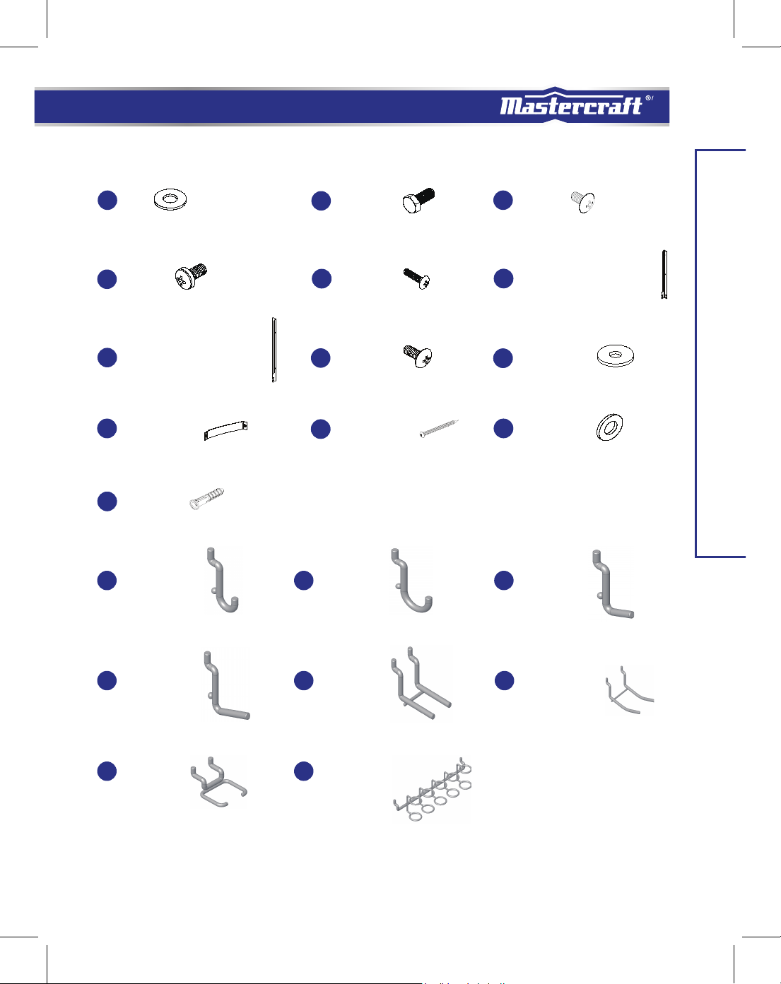
PARTS LIST
No. Qty. No. Qty.Description Description
1
2
3
4
5
6
7
8
9
10A
10E
11A
11B
11C
11D
11E
12
13
14
15
16
17
18-A
18-B
Solid Wood Board
Front Frame
Back Frame
Left Side Panel
Right Side Panel
Middle Shelf
Base Panel
Middlle Panel
Door
Small Drawer Front Panel
Small Drawer Case
Large Drawer Front Panel
Large Drawer Left Panel
Large Drawer Right Panel
Large Drawer Back Panel
Large Drawer Base Panel
Wheel With Brake
Wheel W/O Brake
M8 Washer
M8 x 18L Screw
M4 x 10L Screw
M4 x 8L Screw
Pegboard Support Bar Left
Pegboard Support Bar Right
1
1
1
1
1
1
1
1
1
2
2
2
2
2
2
2
2
2
4
4
80
80
1
1
19
20
21
22
24
25
26
28
29-1
29-2
29-3
29-4
30
42
57
61
27
60
55
27-B
55-A
100 1/2" (12.7 mm) CURVED 4
101 1" (2.5 cm) CURVED 4
102 1" (2.5 cm) STRAIGHT 4
103 1 1/2" (3.8 cm) STRAIGHT 4
104 2" (5.1 cm) DOUBLE PRONG 2
105 4" (10.2 cm) CURVED DOUBLE PRONG 2
106 2" (5.1 cm) PLIER HOLDER 2
107 2" (5.1 cm) MULTI-TOOL HOLDER 1
Push bar
Corner Protector
Screwdriver
Key
Drawer Mat
Wrench
Magnet
Pegboard
Top Cantilever Shelf Back Panel
Top Cantilever Shelf Base Panel
Top Cantilever Shelf Left Panel
Top Cantilever Shelf Right Panel
Top Cantilever Shelf Mat
M4 x 30L Screw
Bumper
M4 x 12L
Washer M4
Mounting Strap
Screw M6 x 50L
Washer M8
Wall Anchor
1
2
1
2
4
1
2
1
1
1
1
1
1
16
4
2
2
2
2
2
2
Page 5
MD
5
M8
14
M4 x 8L
17
18-B
Pegboard Support Bar Right
60
Mounting Strap
Wall Anchor
55-A
1/2" (12.7 mm)
100 101
CURVED
M8 x 18L15
M4 x 30L
42
M4 x 12L
61
55
Screw M6 x 50L
1" (2.5 cm)
CURVED
16
M4 x 10L
18-A
Pegboard Support Bar Left
27
Washer M4
27-B
Washer M8
1" (2.5 cm)
102
STRAIGHT
PARTS LIST
103
1 1/2" (3.8 cm)
STRAIGHT
106
2" (5.1 cm)
PLIER
HOLDER
104
107
2" (5.1 cm)
DOUBLE
PRONG
2" (5.1 cm)
MULTI-TOOL
HOLDER
105
4" (10.2 cm)
CURVED DOUBLE
PRONG
Page 6
6
PARTS LIST
model no. 068-0002-6 contact us 1-800-689-9928
10E
17
10A
11B
11D
11C
11E
6
11A
17
Page 7
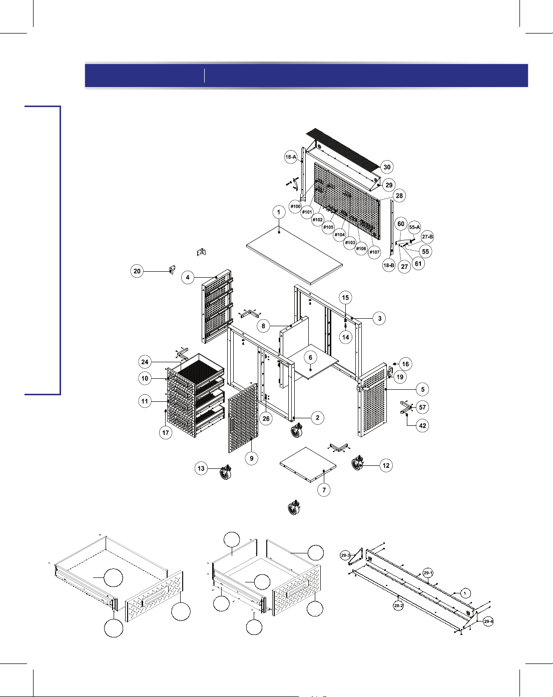
Assembly Preparation
• Assemble the storage cabinet on a clean, level surface.
•
Remove all items from the packaging box and ensure that all parts listed on pages 4-5
are included.
•
When installing parts that have more than one screw, tighten all screws by hand
before tightening them with the screwdriver.
Assembly Instructions
Open both boxes, locate and remove the
fig A
1
1.
cardboard box containing the Solid Hardwood
Top (Part 1). Set the other parts to the side.
When assembling this item, place the Solid
Hardwood Top up side down on the cardboard
to avoid scratching the top surface (
fig A
MD
7
).
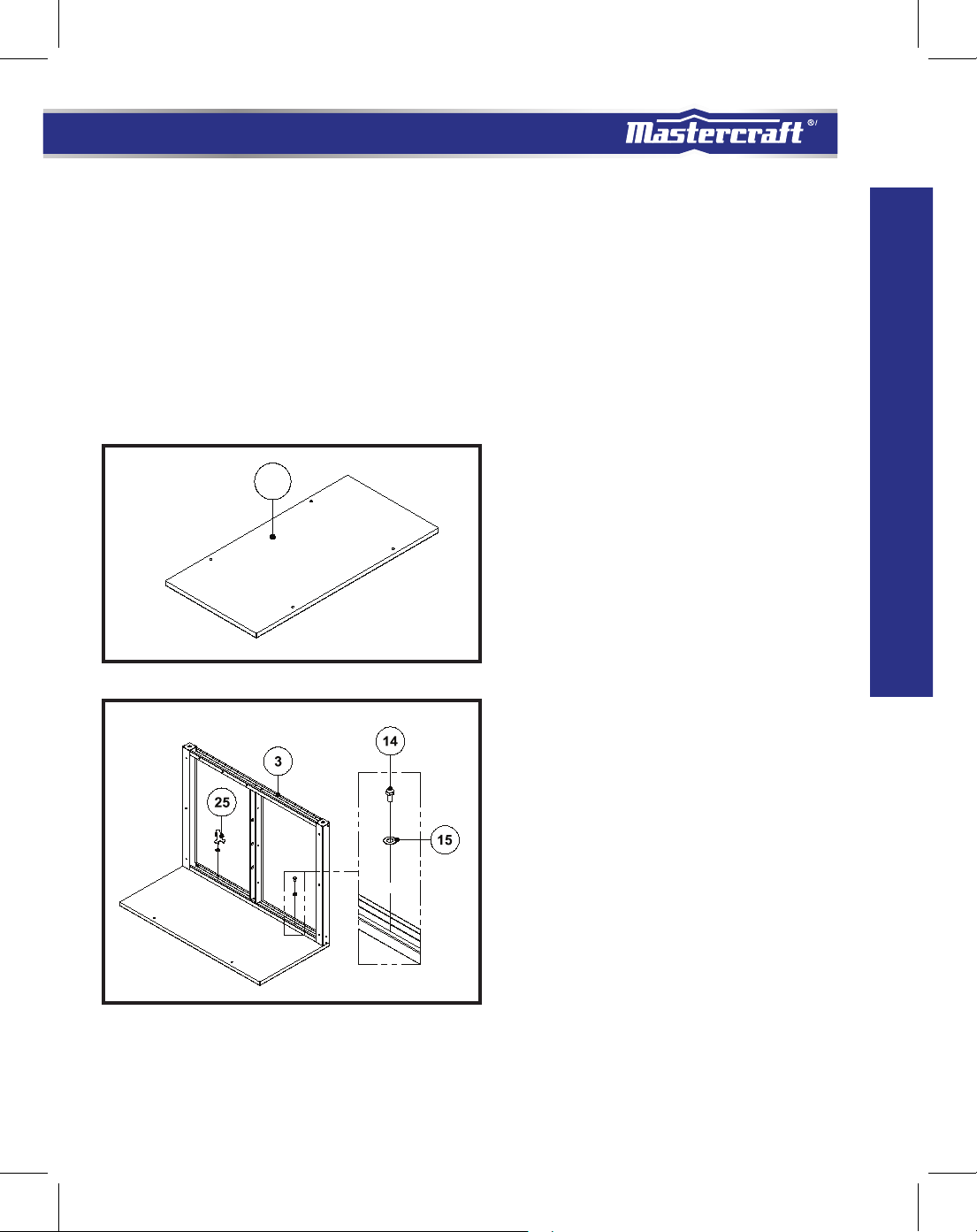
ASSEMBLY INSTRUCTIONS
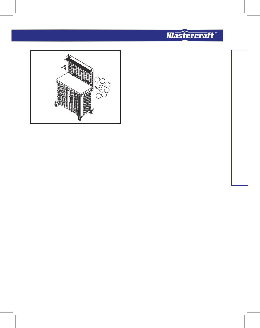
fig B
Install Back Frame (Part 3) to Solid
2.
Hardwood Top (Part 1)
[Use the Wrench (Part 25) for this step]
Place the Back Frame (Part 3) as the left
picture shows and use 2 pcs Screw (Part 14)
and Washers (Part 15) to fasten. Attach the
"Top" of the Back Frame (Part 3), as indicated
by the attached sticker, to the Solid Hardwood
Top (Part 1) (the Solid Hardwood Top has no set
front or back end) (
Note: Ensure the back and side are flush with
the Solid Hardwood Top. When assembling a
part, do not tighten any screws completely
until all screws for that part have been
partially screwed in.
fig B
).
Page 8
8
model no. 068-0002-6 contact us 1-800-689-9928
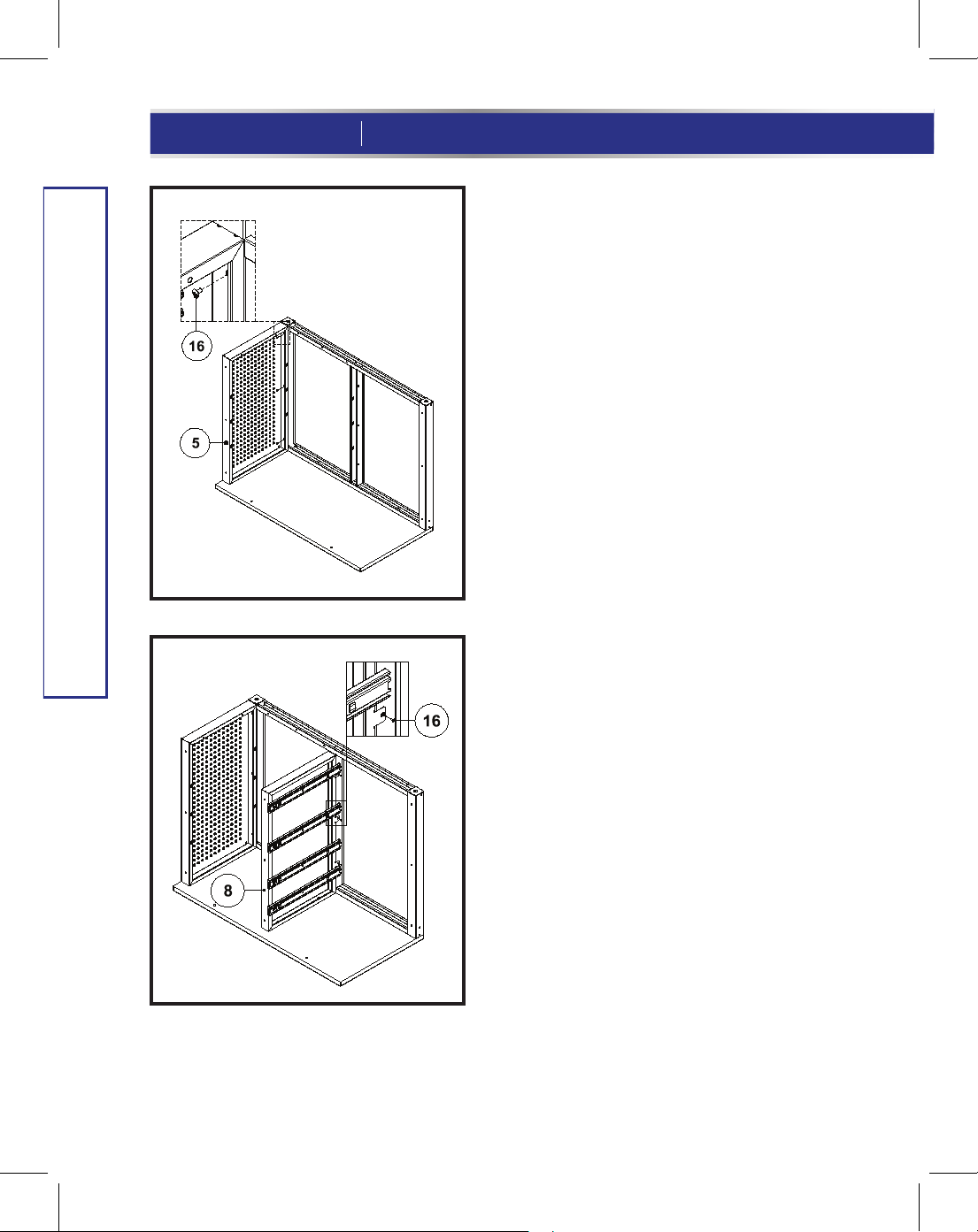
ASSEMBLY INSTRUCTIONS
fig D
fig C
3.
Install Right Side Panel (Part 5).
Attach Right Side Panel (Part 5) to Back Frame (Part 3),
making sure the "Top" of Right Side Panel (Part 5) is
on the Solid Hardwood Top (Part 1). Use 3 pcs of Screw
(Part 16) and Screwdriver (Part 21) to fasten (
Install Middle Panel (Part 8).
4.
Attach the Middle Panel (Part 8) to the Back Frame
(Part 3) and Solid Hardwood Top (Part 1) as the left
picture shows, making sure the "Top" of Middle Panel
(Part 8) is attached on the Solid Hardwood Top (Part 1).
Again, the “Top” is indicated by a sticker on one of the
vertical columns. Use 3 pcs of Screw (Part 16) and
Screwdriver (Part 21) to fasten (
fig D
).
fig C
).
Page 9
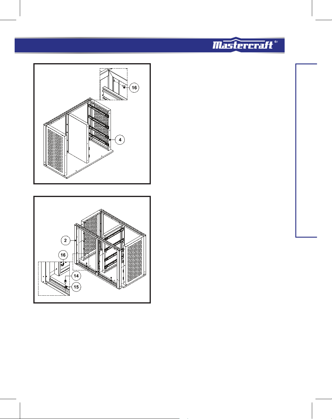
fig E
fig F
Install Left Side Panel (Part 4).
5.
Attach Left Side Panel (Part 4) to Back Frame (Part 3),
making sure the "Top" of Left Side Panel (Part 4) is
on the Solid Hardwood Top (Part 1). Use 3 pcs of
Screw (Part 16) and Screwdriver (Part 21) to fasten
(
fig E
).
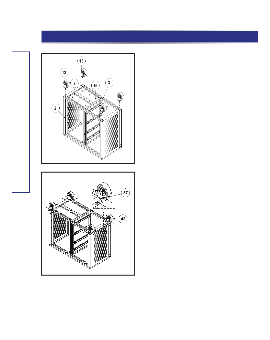
Install The Front Frame (Part 2).
6.
A: Attach the "Top" of the Front Frame
(Part 2) to the Solid Hardwood Top (Part 1).
The other screw holes will align with
the Left and Right Side Panels (Part 4 and 5)
and Middle Panel (Part 8).
MD
9
ASSEMBLY INSTRUCTIONS
B: Use 9 pcs of Screw (Part 16) and
Screwdriver (Part 21) to fasten the Front
Frame (Part 2) on the Left and Right Side
Panels (Part 4 and 5) and Middle Panel (Part 8).
C: Make sure the four edges of the
Cabinet are aligned, then fasten the
Front Frame (Part 2) on the Solid
Hardwood Top (Part 1) by using 2 pcs of
Washer (Part 15) and Screw (Part 14) with
Wrench (Part 25) (
fig E
).
Page 10
10
model no. 068-0002-6 contact us 1-800-689-9928
7.
fig G
Install the Base Panel (Part 7) and
Wheel (Part 12) and (Part 13).
A: Fit the Bottom Panel (Part 7) between the
Back Frame (Part 3) and Front Frame (Part 2) as
shown in Fig G, line up the screw holes
and use 8pcs of Screw (Part 16) to fasten it.
B: Attach Wheels (Part 12 and 13) using the
Wrench (Part 25) to tighten. Make sure that
the Wheels w/o Brakes (Part 13) are on the
Back frame (Part 3), and Wheels with Brakes
(Part 12) are on the Front frame (Part 2
) (
fig G
).
ASSEMBLY INSTRUCTIONS
fig H
Install the Bumper (Part 57).
8.
Attach Bumpers (Part 57) to the bottom
four corners of the Cabinet. Use 16 pcs of
Screw (Part 42) to fasten. Then, rotate/
stand the Cabinet upright (
fig H
).
Page 11
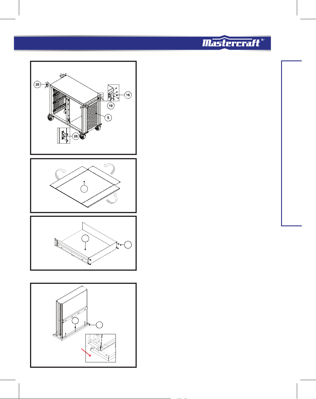
fig I
10E
17
fig J
10E
9.
Install the Corner Protector (Part 20),
the Push Bar (Part 19) and Magnet
(Part 26).
A: Attach the Corner Protector (Part 20) to left side
panel (Part 4), and use 8 pcs Screw (Part 16) to
tighten.
B: Attach the Push Bar (Part 19) to right side panel
(Part 5), and use 12 pcs Screw (Part 16) to
tighten.
C: Use 4 pcs of Screw (Part 16) to fasten
the Magnet (Part 26) on the Front Frame (Part 2)
(
fig I
).
MD
11
ASSEMBLY INSTRUCTIONS
fig K
fig L
Assemble the Small Drawer (Part 10).
10.
A: Fold up all three panels of the Small Drawer Body
(Part 10E) and use Screw (Part 17) to tighten the
back panel
to the Left and Right Side Panels (
B: Insert the Small Drawer Body (Part 10E) into the
Small
Drawer Front Panel (Part 10A) and use Screw (Part
17) to tighten (
C: Repeat A and B to assemble another small
drawer.
17
10A
fig L
).
fig J and fig K
).
Page 12

12
model no. 068-0002-6 contact us 1-800-689-9928
11.
Assemble Large Drawer Side Panels.
fig M
11C
11B
17
11A
fig N
Fit and attach Large Drawer Side Panels (Part 11C
and 11B) one at a time, into the back of the stainless
steel Large Drawer Front (Part 11A). Make sure the
Drawer Side Panels are placed in all the way making
contact with the rear of the Large Drawer Front
Panel (Part 11A). Line up the screw holes and use
Screw (Part 17) to tighten them (
12.
Assemble the Large Drawer Base
Panel (Part 11E).
fig M
).
11E
ASSEMBLY INSTRUCTIONS
11D
Insert the Large Drawer Base Panel (Part 11E)
17
fig O
17
between the two sides and into the back of
the Large Drawer Front Panel (Part 11A). Use
Screw (Part 17) to tighten (
Assemble the Larger Drawer
13.
fig N
Back Panel (Part 11D).
Attach the Large Drawer Back Panel (Part
11D) to the rest of the assembled drawer.
Use Screw (Part 17) to tighten. Once you
have the Large Drawer assembled, repeat
Steps 11-13 to assemble another Large
Drawer; you should have two Large
Drawers and two Small Drawers (
).
fig O
).
Page 13

14.
Place the Drawers.
A: Pull out the sliders completely, then attach the
drawer to the sliders. Make sure the square holes
on the drawer side panels are lined up, and the
drawer is hooked onto the sliders completely
(
fig P and fig Q
).
MD
13
fig P
fig Q
B: Use 4 pcs Screw (Part 17) to tighten the
drawer, and put the Drawer Mat (Part 24) into
the drawer (
Repeat above steps to place other drawers.
Note: Do not tighten any screws completely
until all the drawers are adjusted well.
fig R
).
Note: Pull out the ball
bearing track completely
before you attach drawer.
fig R
ASSEMBLY INSTRUCTIONS
The oval hole at the front of the slider allows for the gaps
between the drawers to be adjusted. Make the adjustments
once all the drawers are installed.
Page 14

14
model no. 068-0002-6 contact us 1-800-689-9928
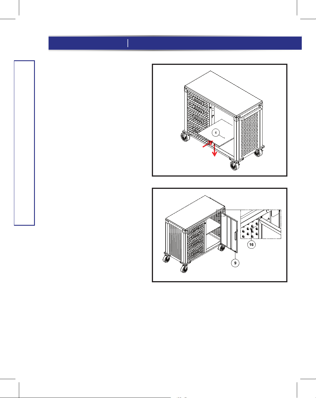
15.
Install the Middle Shelf
(Part 6).
Place the Middle Shelf (Part 6) in the
unit at the desired height and ensure
that all four corners are secured on
the hooks on the Front and Back
Frame (
Install the Door (Part 9).
16.
ASSEMBLY INSTRUCTIONS
Attach the Door (Part 9) to the right
side of the Cabinet. Use 5 pcs Screw
(Part 16) to fasten (
fig S
fig S
).
fig T
fig T
).
Page 15

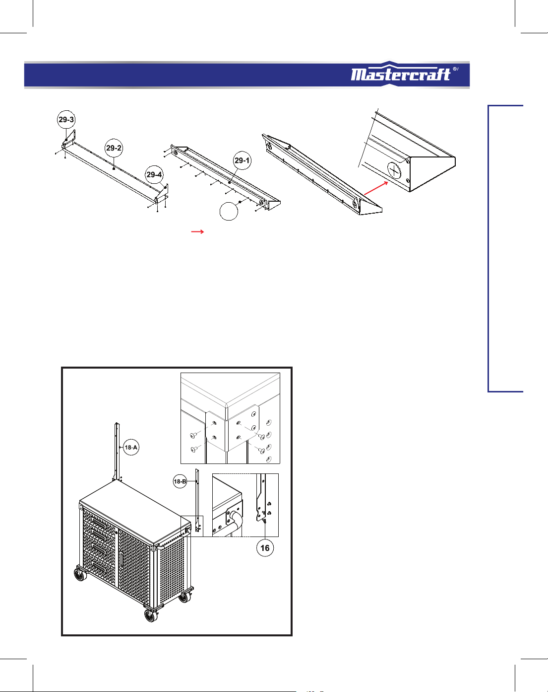
16
A B
Install the Top Cantilever Shelf.
17.
A : Attach the Top Cantilever Shelf Left Panel (Part 29-3) and the Top Cantilever Shelf Right Panel
(Part 29-4) to Top Cantilever Shelf Base Panel (Part 29-2). Use Screws (Part 16) to tighten.
B: Attach the Top Cantilever Shelf back Panel (Part 29-1) to the Top Cantilever Shelf Right Panel
(Part 29-4) and Left Panel (2Part 9-3) and Base Panel (Part 29-2). Use Screws (Part 16) to tighten.
MD
15
ASSEMBLY INSTRUCTIONS
fig U
Install Pegboard Support Bar
18.
(Part 18-A) and (Part 18-B)
A: Please take off left and right side corner
protector screws, total 16 pcs.
B: Attach Pegboard left and right support
Bar to the back of the work centre, line up
the screw holes, and use (Part 16) Screw to
tighten (
fig U
).
Note: Do not fully tighten the screws. This
will help you make any adjustments to
alignment later.
Page 16
16
model no. 068-0002-6 contact us 1-800-689-9928
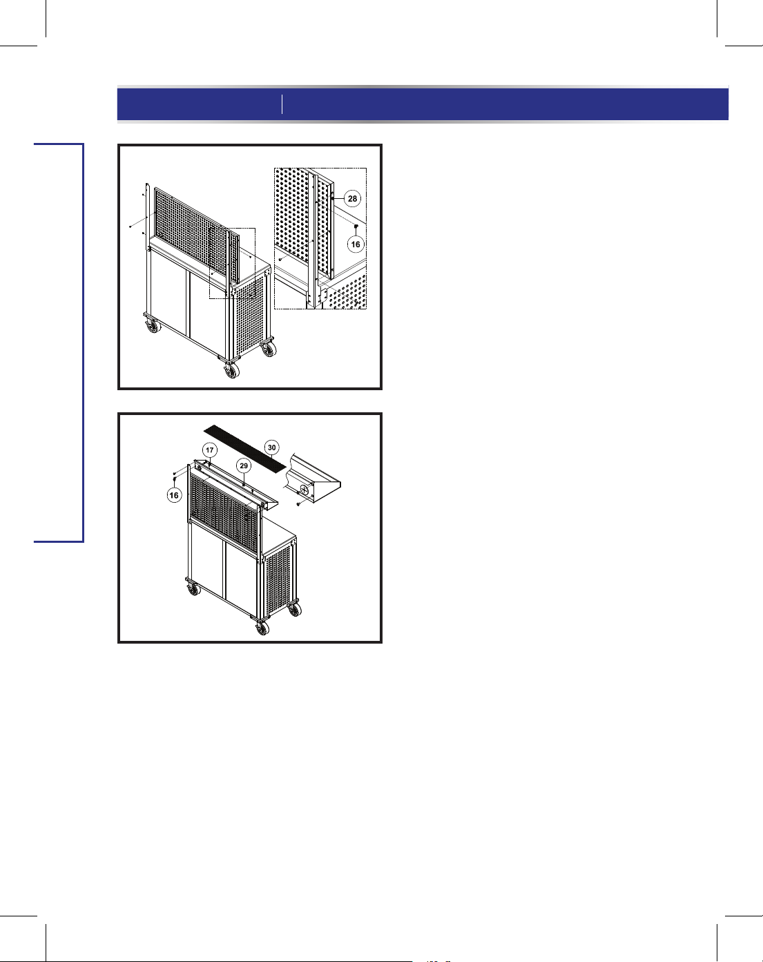
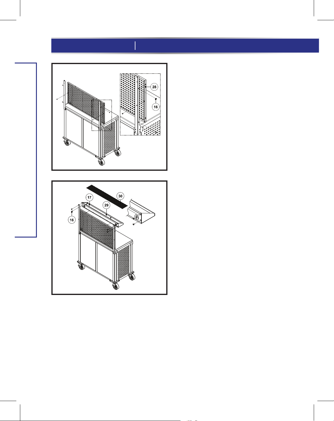
Install Pegboard (Part 28).
19.
fig V
Attach the Pegbord (Part 28) to the support bar,
line up the screw holes, and use 6 pcs screw
(Part 16) to tighten (
Install Top Cantilever Shelf
20.
fig W
(Part 29) to work centre.
fig V
).
ASSEMBLY INSTRUCTIONS
A: Please take off left and right side of
Top Cantilever Shelf screws, total 4 pcs.
B: Attach Top Cantilever Shelf to the Top
of Pegboard (Part 28) and Pegboard
Support Bars, line up the screw holes,
and use Screw (Part 16) to tighten it to
Pegboard Support Bars, and use Screw
(Part 17) to tighten it to the Top of
Pegboard (Part 28) (
fig W
).
Page 17
MD
17
fig X
21. Install Mounting Strap (Part 60)
(
fig X
).
A. Remove 1 pc Screw (Part 16) from the back
60
55-A
27-B
55
61
27
corner protection.
B. Attach the Mounting Strap (Part 60) to the
back Corner Protection brackets as the left
photo shows using Screw (Part 61) and
Washer (Part 27).
C. Drill a hole in the wall with a 5/16" drill bit,
insert the Wall Anchor (Part 55-A) into the hole.
D. Attach the other end of the Mounting Strap
(Part 60) to the wall using Screw M (Part 55)
and Washer (Part 27-B).
Repeat steps A through D to install the other
mounting strap.
ASSEMBLY INSTRUCTIONS
Stainless Steel Maintenance:
These parts have an fingerprint-resistant finish. Do not use traditional stainless steel cleaners on this unit.
Lightly wipe off once a month with clean warm water and a soft cloth (preferably a microfibre cloth). This is
the safest formula to prevent new stains from appearing over time and manage unwanted fingerprints or
grease marks. Remember to always wipe in the direction of the surface grain (NEVER ACROSS) and always
use a lint-free cloth. Once the surface is clean, thoroughly wipe dry with a soft, absorbent cloth.
Page 18

18
WARRANTY
model no. 068-0002-6 contact us 1-800-689-9928
This Mastercraft product is guaranteed for a period of one (1) year from the date of original retail purchase, against
defects in materials and workmanship.
Subject to the conditions and limitations described below, this product, if returned to us with proof of purchase within
the stated warranty period and if covered under this warranty, will be repaired or replaced (with the same model, or one
of equal value or specification), at our option. We will bear the cost of any repair or replacement and any costs of labour
relating thereto.
These warranties are subject to the following conditions and limitations
a. a bill of sale verifying the purchase and purchase date must be provided;
b. this warranty will not apply to any product or part thereof which is worn or broken or which has become inoperative due
to abuse, misuse, accidental damage, neglect or lack of proper installation, operation or maintenance (as outlined in the
applicable owner’s manual or operating instructions) or which is being used for industrial, professional, commercial or rental
purposes;
c. this warranty will not apply to normal wear and tear or to expendable parts or accessories that may be supplied with the
product which are expected to become inoperative or unusable after a reasonable period of use;
d. this warranty will not apply to routine maintenance and consumable items such as, but not limited to, fuel, lubricants, vacuum
bags, blades, belts, sandpaper, bits, fluids, tune-ups or adjustments;
e. this warranty will not apply where damage is caused by repairs made or attempted by others (i.e. persons not authorized by
the manufacturer);
f. this warranty will not apply to any product that was sold to the original purchaser as a reconditioned or refurbished product
(unless otherwise specified in writing);
g. this warranty will not apply to any product or part thereof if any part from another manufacturer is installed therein or any
repairs or alterations have been made or attempted by unauthorized persons;
h. this warranty will not apply to normal deterioration of the exterior finish, such as, but not limited to, scratches, dents, paint
chips, or to any corrosion or discolouring by heat, abrasive and chemical cleaners; and
i. this warranty will not apply to component parts sold by and identified as the product of another company, which shall be
covered under the product manufacturer’s warranty, if any.
Additional Limitations
This warranty applies only to the original purchaser and may not be transferred. Neither the retailer not the manufacturer
shall be liable for any other expense, loss or damage, including, without limitation, any indirect, incidental, consequential
or exemplary damages arising in connection with the sale, use or inability to use this product.
Notice to Consumer
This warranty gives you specific legal rights, and you may have other rights, which may vary from province to province.
The provisions contained in this warranty are not intended to limit, modify, take away from, disclaim or exclude any
statutory warranties set forth in any applicable provincial or federal legislation.
Imported by Mastercraft Canada Toronto, Canada M4S 2B8
Page 19

MD
N° de modèle: 068-0002-6
Poste de travail à dessus de type de bloc de boucher
IMPORTANT :
Veuillez lire attentivement ce guide d’utilisation avant d'installer ce
poste de travail et le conserver aux fins de consultation ultérieure.
GUIDE
D’UTILISATION
Page 20

2
N° de modèle: 068-0002-6 communiquez avec nous au 1 800 689-9928
TABLE DES MATIÈRES
Consignes de sécurité
Liste des pièces
Instructions d'assemblage
Garantie
3
4
7
18
REMARQUE:
Si des pièces sont manquantes ou endommagées, ou si vous avez
des questions, veuillez appeler notre service d’assistance téléphonique
sans frais au 1 800 689-9928.
CONSERVEZ CES INSTRUCTIONS
Ce guide contient des consignes de sécurité et d’utilisation importantes.
Lisez et respectez toutes les instructions lorsque vous utilisez cet article.
Page 21

MD
CONSIGNES DE SÉCURITÉ
Le présent guide contient des renseignements relatifs à la SÉCURITÉ PERSONNELLE et à la PRÉVENTION
DES PROBLÈMES D’ÉQUIPEMENT. Il est très important de lire attentivement et de bien comprendre ce
manuel avant d’utiliser le produit. Les symboles ci-dessous servent à indiquer ces informations.
• Le poste de travail doit être placé sur une surface plane.
• Il est destiné à être utilisé à l'intérieur uniquement.
• Vérifiez périodiquement que tous les écrous et boulons sont serrés.
• Utilisez un chiffon doux humide pour nettoyer le poste de travail.
• Ne montez pas sur le poste de travail et ne l'utilisez pas comme échafaudage.
• Ne dépassez pas la charge maximale de 871lb (396kg).
• L'assemblage et l'entretien de ce poste de travail ne doivent être effectués que par des adultes.
• Faites équipe avec quelqu'un pour assembler et déplacer le poste de travail.
• N’excédez pas les limites de poids suivantes pour ce produit:
3
CONSIGNES DE SÉCURITÉ
Charge maximale sur le dessus de l’armoire à table de travail: 430lb (195,4kg)
Charge maximale sur le panneau inférieur: 90lb (40kg)
Charge maximale sur la tablette: 70lb (31,8kg)
Charge maximale par tiroir: 40 lb (18 kg)
Charge maximale pour le panneau perforé: 88lb (40kg)
Charge maximale sur la tablette supérieure: 33 lb (15 kg)
Capacité totale: 871 lb (396 kg)
Page 22

4
N° de modèle: 068-0002-6 communiquez avec nous au 1 800 689-9928
LISTE DES PIÈCES
No. Qty. No. Qty.Description Description
1
2
3
4
5
6
7
8
9
10A
10E
11A
11B
11C
LISTE DES PIÈCES
11D
11E
12
13
14
15
16
17
18-A
18-B
19
Plan de travail en bois massif
Châssis avant
Châssis arrière
Panneau latéral gauche
Panneau latéral droit
Tablette intermédiaire
Panneau inférieur
Panneau central
Porte
Panneau avant du petit tiroir
Petit tiroir
Panneau avant du grand tiroir
Panneau gauche du grand tiroir
Panneau droit du grand tiroir
Panneau arrière du grand tiroir
Panneau inférieur du grand tiroir
Roulette verrouillable
Roulette non verrouillable
Rondelle M8
Vis M8x 18L
Vis M4x 10L
Vis M4x 8L
Barre de support gauche
du panneau perforé
Barre de support droite
du panneau perforé
Barre de tirage
1
1
1
1
1
1
1
1
1
2
2
2
2
2
2
2
2
2
4
4
80
80
1
1
1
20
Protecteur de coin
21
Tournevis
22
Clé
24
Panneau de tiroir
25
Clé
26
Aimant
28
Panneau perforé
29-1
Panneau arrière de la tablette supérieure en
porte-à-faux
29-2
Panneau de base de la tablette supérieure en
porte-à-faux
29-3
Panneau gauche de la tablette supérieure en
porte-à-faux
29-4
Panneau droit de la tablette supérieure en
porte-à-faux
30
Tapis pour tablette supérieure en porte-à-faux
42
Vis M4x 30L
57
Pare-choc
61
M4 x 12L
27
Rondelle M4
60
Sangle de fixation
55
Vis M6 x 50L
27-B
Rondelle M8
55-A
Cheville d'ancrage
100
CROCHET COURBÉ DE 1/2 po (12,7 mm)
101
CROCHET COURBÉ DE 1 po (2,5 cm)
102
CROCHET DROIT DE 1 po (2,5 cm)
103
CROCHET DROIT DE 11/2 po (3,8 cm)
104
FOURCHON DE 2po(5,1cm)
105
FOURCHON COURBÉ DE 4po(10,2 cm)
106
SUPPORT À PINCE DE 2po (5,1cm)
107
SUPPORT À OUTILS MULTIPLES DE 2po
(5,1 cm)
2
1
2
4
1
2
1
1
1
1
1
1
16
4
2
2
2
2
2
2
4
4
4
4
2
2
2
1
Page 23

MD
5
M8
14
17
M4 x 8L
18-B
Barre de support droite
du panneau perforé
60
Sangle de fixation
55-A
Cheville d'ancrage
100 101
CROCHET COURBÉ DE
1/2 po (12,7 mm)
M8 x 18L15
42
M4 x 30L
M4 x 12L
61
55
Vis M6 x 50L
CROCHET COURBÉ DE
1 po (2,5 cm)
M4 x 10L
16
18-A
Barre de support gauche
du panneau perforé
Rondelle M4
27
27-B
Rondelle M8
102
CROCHET DROIT DE
1 po (2,5 cm)
LISTE DES PIÈCES
103
CROCHET DROIT DE
11/2 po (3,8 cm)
106
SUPPORT À PINCE DE
2po (5,1cm)
104
FOURCHON DE
2po(5,1cm)
107
SUPPORT À OUTILS MULTIPLES DE
2po (5,1 cm)
105
FOURCHON COURBÉ DE
4po(10,2 cm)
Page 24

6
N° de modèle: 068-0002-6 communiquez avec nous au 1 800 689-9928
LISTE DES PIÈCES
10E
17
10A
11B
11D
11C
11E
6
11A
17
Page 25

Instructions d’assemblage
• Assemblez l’armoire de rangement sur une surface plane et propre.
•
Sortez toutes les pièces de l’emballage et consultez les pages 4 et 5 pour vérifier qu’il n’en
manque pas.
•
Lors de l’assemblage de pièces nécessitant plus d’une vis, serrez les vis à la main avant
de les serrer avec le tournevis.
Instructions d’assemblage
Ouvrez les deux cartons; repérez le dessus en
fig A
1
1.
bois massif (1) et sortez-le du carton. Mettez
de côté les autres pièces. Lors de l'assemblage de cette pièce, placez le dessus en bois
massif à l'envers sur le carton pour éviter les
rayures sur la surface supérieure (
fig A
MD
7
).
INSTRUCTIONS D’ASSEMBLAGE
fig B
Installez le châssis arrière (3) au
2.
dessus en bois massif (1).
[Utilisez la clé (25) pour cette étape] Placez le
châssis arrière (3) comme indiqué ci-contre et
fixez-le au moyen de 2 vis (14) et des rondelles
(15). Fixez le haut du châssis arrière (3),
comme indiqué sur l'autocollant au dessus en
bois massif (1) (le dessus en bois massif n'a
pas de côté avant/arrière défini)
(
fig B
).
Remarque : Vérifiez que l'arrière et le côté
sont alignés avec le dessus en bois massif.
Lors de l'assemblage d'une pièce, ne serrez
pas complètement les vis tant qu'elles n'ont
pas toutes été partiellement vissées.
Page 26

8
N° de modèle: 068-0002-6 communiquez avec nous au 1 800 689-9928
INSTRUCTIONS D’ASSEMBLAGE
fig D
fig C
3.
Installez le panneau latéral droit (5).
Fixez le panneau latéral droit (5) au châssis arrière (3),
en veillant à ce que le haut du panneau latéral droit (5)
se trouve sur le dessus en bois massif (1). Utilisez 3 vis
(16) et le tournevis (21) pour fixer (
Installez le panneau central (8).
4.
Fixez le panneau central (8) au châssis arrière (3) et au
dessus en bois massif (1), comme indiqué ci-contre,
en veillant à ce que le haut du panneau central (8) soit
fixé au dessus en bois massif (1). Le « haut » est
indiqué par un autocollant situé sur l'une des colonnes.
Utilisez 3 vis (16) et le tournevis (21) pour fixer (
fig C
).
fig D
).
Page 27

fig E
fig F
Installez le panneau latéral gauche (4).
5.
Fixez le panneau latéral gauche (4) au châssis arrière
(3), en veillant à ce que le haut du panneau latéral
gauche (4) se trouve sur le dessus en bois massif (1).
Utilisez 3 vis (16) et le tournevis (21) pour fixer (
Installez le châssis avant (2).
6.
A : Fixez le haut du châssis avant (2) au dessus en
bois massif (1). Les autres trous de vis s'aligneront
aux panneaux latéraux gauche et droit (4 et 5) ainsi
qu'au panneau central (8).
fig E
MD
9
).
INSTRUCTIONS D’ASSEMBLAGE
B : Utilisez 9 vis (16) et le tournevis (21) pour fixer le
châssis avant (2) aux panneaux latéraux gauche et
droit (4 et 5) ainsi qu'au panneau central (8).
C : Vérifiez que les quatre côtés de l'armoire sont
alignés, puis fixez le châssis avant (2) au dessus en
bois massif (1) au moyen de 2 rondelles (15), des vis
(14) et la clé (25) (
fig E
).
Page 28

10
N° de modèle: 068-0002-6 communiquez avec nous au 1 800 689-9928
7.
fig G
Fixez le panneau inférieur (7) et
les roulettes (12 et 13).
A : Insérez le panneau inférieur (7) entre le
châssis arrière (3) et le châssis avant (2),
comme indiqué à la figure G, alignez les trous
de vis et fixez-le au moyen des 8 vis (16).
B : Fixez les roulettes (12 et 13) à l'aide de la
clé (25) pour serrer. Assurez-vous que les
roulettes non verrouillables (13) sont fixées au
châssis arrière (3) et que les roulettes
verrouillables (12) sont fixées au châssis avant
(2) (
fig G
).
INSTRUCTIONS D’ASSEMBLAGE
fig H
8.
Installez les pare-chocs (57).
Fixez les pare-chocs (57) aux quatre coins
inférieurs de l'armoire. Utilisez 16 vis (42)
pour serrer. Mettez ensuite l’armoire
debout (
fig H
).
Page 29

fig I
fig J
10E
9.
Installez le protecteur de coin (20),
les barres de tirage (19) et l'aimant
(26).
A : Fixez le protecteur de coin (20) au panneau
latéral gauche (4) au moyen de 8 vis (16).
B : Fixez la barre de tirage (19) au panneau
latéral droit (2) au moyen de 12 vis (16).
C : Utilisez 4 vis (16) pour fixer les aimants (26)
au châssis avant (2) (
fig I
).
MD
11
INSTRUCTIONS D’ASSEMBLAGE
fig K
fig L
10. Assemblez le petit tiroir (10).
10E
17
17
10A
A : Relevez les trois panneaux du petit tiroir (10E) et
utilisez des vis (17) pour fixer le panneau arrière aux
panneaux latéraux gauche et droit (
B : Insérez le corps du petit tiroir (10E) dans le
panneau avant du petit tiroir (10A) et utilisez des vis
(17) pour fixer les parties (
C : Répétez les étapes A et B pour assembler l'autre
petit tiroir.
fig L
).
fig. J et K
).
Page 30

12
N° de modèle: 068-0002-6 communiquez avec nous au 1 800 689-9928
11.
Assemblez les panneaux latéraux du
11C
fig M
grand tiroir.
11B
11A
11E
17
INSTRUCTIONS D’ASSEMBLAGE
17
11D
17
fig N
fig O
Fixez un à un les panneaux latéraux du grand tiroir
(11C et 11B) à l'arrière du panneau avant du grand
tiroir en inox (11A). Vérifiez que les panneaux
latéraux du tiroir touchent l'arrière du panneau avant
du grand tiroir (11A). Alignez les trous de vis et
utilisez des vis (17) pour fixer le tout (
12.
Assemblez le panneau inférieur
fig M
du grand tiroir (11E).
Insérez le panneau inférieur du grand tiroir
(11E) entre les deux côtés et à l'arrière du
panneau avant du grand tiroir (11A). Utilisez
des vis (17) pour fixer (
Installez le panneau arrière du
13.
fig N
).
grand tiroir (11D).
).
Fixez le panneau arrière du grand tiroir
(11D) au reste du tiroir assemblé au
moyen des vis (17). Une fois le grand tiroir
assemblé, répétez les étapes 11 à 13 pour
assembler l'autre grand tiroir. Vous
devriez avoir deux grands tiroirs et deux
petits tiroirs (
fig O
).
Page 31

14.
Placez les tiroirs.
A : Sortez complètement les coulisses, puis fixez le
tiroir aux coulisses. Assurez-vous que les trous
carrés des panneaux latéraux des tiroirs sont
alignés et que les tiroirs sont complètement
accrochés aux coulisses (
fig P and fig Q
MD
13
fig P
).
fig Q
B : Utilisez 4 vis (17) pour assembler le tiroir,
puis placez le tapis de tiroir (24) au fond du
tiroir (
fig R
).
Répétez les étapes ci-dessus pour installer
les autres tiroirs.
Remarque : Sortez complètement
le système de roulement à billes
avant de fixer le tiroir
fig R
INSTRUCTIONS D’ASSEMBLAGE
Remarque : Ne serrez pas complètement les
vis tant que tous les tiroirs ne sont pas bien
ajustés.
Le trou ovale situé à l'avant des coulisses permet d'ajuster
l'écart entre les tiroirs. Faites les ajustements nécessaires
une fois que tous les tiroirs sont installés.
Page 32
14
N° de modèle: 068-0002-6 communiquez avec nous au 1 800 689-9928
15.
Installez la tablette
intermédiaire (6).
Placez la tablette intermédiaire
(6) dans l’armoire, à la hauteur
désirée, et vérifiez que les quatre
coins sont retenus par les
crochets des châssis avant et
arrière (
fig S
).
Installez la porte (9).
16.
INSTRUCTIONS D’ASSEMBLAGE
Fixez la porte (9) au côté droit de
l'armoire. Utilisez 5 vis (16) pour fixer
(
fig T
).
fig S
fig T
Page 33
16
A B
Installez la tablette supérieure en porte-à-faux.
17.
A : Fixez le panneau gauche de la tablette supérieure en porte-à-faux (29-3) et le panneau droit de la
tablette supérieure en porte-à-faux (29-4) sur le panneau inférieur de la tablette en porte-à-faux
(29-2) au moyen des vis (16).
B : Fixez le panneau arrière de la tablette supérieure en porte-à-faux (29-1) au panneau droit de la
tablette supérieure en porte-à-faux (29-4), au panneau gauche (29-3) et au panneau inférieur (29-2)
à l’aide des vis (16).
MD
15
INSTRUCTIONS D’ASSEMBLAGE
fig U
Installez la barre de support du
18.
panneau perforé (18-A) et
(18-B).
A : Enlevez les vis des protecteurs de coins
gauche et droit, 16 en tout.
B : Assemblez la barre de support gauche et
droite du panneau perforé à l'arrière du
poste de travail, alignez les trous de vis,
puis fixez au moyen des vis (16) (
Remarque : Ne serrez pas complètement les
vis. Cela vous permettra de faire les
ajustements nécessaires par la suite.
fig U
).
Page 34
16
N° de modèle: 068-0002-6 communiquez avec nous au 1 800 689-9928
fig V
fig W
INSTRUCTIONS D’ASSEMBLAGE
Installez le panneau perforé (28).
19.
Assemblez le panneau perforé (28) à la barre de
support, alignez les trous de vis, puis fixez au
moyen de 6 vis (16) (
Installez la tablette supérieure
20.
fig V
).
en porte-à-faux (29) au poste
de travail.
A : Enlevez les vis des la tablette
supérieure en porte-à-faux gauche et
droit, 4 en tout.
B : Assemblez la tablette supérieure en
porte-à-faux au haut du panneau perforé
(28) et aux barres de support du panneau
perforé, alignez les trous de vis, et
utilisez la vis (partie 16) pour la serrer
aux barres de support du panneau
perforé, et utilisez la vis (partie 17) pour
la serrer au panneau perforé (28) (
fig W
).
Page 35

MD
17
fig X
21. Installez une sangle de fixation
(pièce 60)
A. Retirez une vis (pièce 16) du protecteur de
60
55-A
27-B
55
61
27
coin arrière.
B. Fixez une sangle de fixation (pièce 60) au
support de protecteur de coin arrière comme
indiqué sur la photo à gauche au moyen d’une
vis (pièce 61) et d’une rondelle (pièce 27).
C. Percez un trou dans le mur à l’aide d’une
mèche de 5/16 po, puis insérez une cheville
d’ancrage (pièce 55-A) dans le trou.
D. Fixez l'autre extrémité de la sangle de
fixation (pièce 60) au mur au moyen d’une vis
M (pièce 55) et d’une rondelle (pièce 27-B).
Répétez les étapes A à D pour installer l'autre
sangle de fixation.
(
fig X
).
INSTRUCTIONS D’ASSEMBLAGE
Entretien de l'acier inoxydable :
Ces pièces ont une finition résistante aux empreintes. N'utilisez pas de nettoyants pour acier inoxydable sur
ce meuble.
Une fois par mois, essuyez-le délicatement avec de l'eau tiède propre et un chiffon doux (de préférence un
chiffon en microfibre). Il s'agit du meilleur moyen de prévenir l'apparition de nouvelles traces au fil du
temps et d'éliminer les traces de doigts ou les taches de graisse. N'oubliez pas de toujours essuyer dans le
sens du fil du bois (JAMAIS DANS LE SENS CONTRAIRE) avec un chiffon non pelucheux. Une fois la surface
nettoyée, séchez-la soigneusement avec un chiffon doux absorbant.
Page 36

18
Cet article Mastercraft est garanti pendant une période d’un (1) an à compter de la date de l’achat original contre les
défauts de fabrication et de matériau(x).
Sous réserve des conditions et restrictions décrites ci-dessous, cet article, s’il nous est retourné accompagné de la
preuve d’achat durant la période de garantie définie et qu’il est protégé en vertu de cette garantie, sera réparé ou
remplacé, à notre gré, par le même modèle ou un modèle de valeur égale ou ayant les mêmes caractéristiques. Nous
assumerons le coût de tout remplacement ou réparation ainsi que les frais de main-d’œuvre s’y rapportant.
Ces garanties sont assujetties aux conditions et restrictions suivantes:
a) un contrat de vente attestant l’achat et la date d’achat doit être fourni;
b) la présente garantie ne s’applique à aucun produit ou pièce d’un produit qui est usé ou brisé, qui est devenu hors
d’usage en raison d’un emploi abusif ou inapproprié, d’un dommage accidentel, d’une négligence ou d’une installation, d’une utilisation ou d’un entretien inappropriés (selon la description figurant dans le guide d’utilisation ou le mode
d’emploi applicable) ou qui est utilisé à des fins industrielles, professionnelles, commerciales ou locatives;
c) la présente garantie ne s’applique pas à l’usure normale ou aux pièces ou accessoires non réutilisables qui sont
fournis avec le produit et qui deviendront vraisemblablement inutilisables ou hors d’usage après une période d’utilisation raisonnable;
d) la présente garantie ne s’applique pas à l’entretien régulier et aux articles de consommation comme le carburant,
les lubrifiants, les sacs d’aspirateur, les lames, les courroies, le papier abrasif, les embouts, les mises au point ou les
réglages;
e) la présente garantie ne s’applique pas lorsque les dommages sont causés par des réparations ou des tentatives de
GARANTIE
réparation faites par des tiers (c’est-à-dire des personnes non autorisées par le fabricant);
f) la présente garantie ne s’applique à aucun produit qui a été vendu à l’acheteur original à titre de produit remis en
état ou remis à neuf (à moins qu’il n’en soit prévu autrement par écrit);
g) la présente garantie ne s’applique à aucun produit ou pièce de produit lorsqu’une pièce d’un autre fabricant est
installée dans celui-ci ou que des réparations ou modifications ou tentatives de réparation ou de modification ont été
faites par des personnes non autorisées;
h) la présente garantie ne s’applique pas à la détérioration normale du fini extérieur, incluant sans s’y limiter, les
éraflures, les bosselures et les éclats de peinture, ou à la corrosion ou à la décoloration causée par la chaleur, les
produits abrasifs et les produits de nettoyage chimiques;
i) la présente garantie ne s’applique pas aux pièces vendues par une autre entreprise et décrites comme telles,
lesquelles pièces sont couvertes par la garantie du fabricant s’y rapportant, le cas échéant.
N° de modèle: 068-0002-6 communiquez avec nous au 1 800 689-9928
Restrictions supplémentaires
La présente garantie s’applique uniquement à l’acheteur original et ne peut être transférée. Ni le détaillant ni le
fabricant ne sont responsables des autres frais, pertes ou dommages, y compris les dommages indirects, accessoires, consécutifs ou exemplaires liés à la vente ou à l’utilisation du présent produit ou à l’impossibilité de l’utiliser.
Avis au consommateur
La présente garantie vous confère des droits spécifiques reconnus par la loi. Vous pourriez disposer de droits supplémentaires qui varient d’une province à l’autre.
Les dispositions figurant dans cette garantie ne visent pas à limiter, à modifier, à éliminer, à rejeter ni à exclure toute
garantie réglementaire établie dans une loi provinciale ou fédérale applicable.
Importé par Mastercraft Canada Toronto, Canada M4S 2B8
Fabriqué en Chine
 Loading...