

Page 1
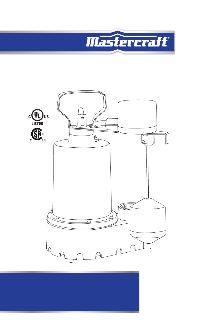
model no. 062-3404-4
R
Submersible
SUMP PUMP
IMPORTANT:
Please read this manual carefully before installing
or operating this sump pump. Save this manual for
future reference.
INSTRUCTION
MANUAL
Page 2

headline bars
Page 3

TABLE OF CONTENTS
Technical Specifications 4
Safety Guidelines 6
Installation Instructions 8
Operation and Maintenance 9
Key Parts Diagram 10
Troubleshooting 11
Warranty Information 12
3
TABLE OF CONTENTS
NOTE:
If any parts are missing or damaged, or if you have any questions, please call our
toll-free helpline at 1-800-689-9928.
SAVE THESE INSTRUCTIONS
This manual contains important safety and operating instructions.
Read all instructions and follow them with use of this product.
Page 4

headline bars
headline bars
4
TECHNICAL SPECIFICATIONS
model no. 062-3404-4 | contact us: 1-800-689-9928
MOTOR SPECIFICATIONS
Horsepower 1/3
Voltage 115
Amps 4.1
Hertz 60 Hz
Phase Single
RPM 3450 RPM
Motor Type Permanent split capacitor (PSC)
Insulation Class A
Circuit Requirements 15 A (min) individual circuit
Duty Rating Continuous*
Shaft Seal Carbon/ceramic and stainless steel
Motor Shaft Stainless steel
Upper Motor Bearing Ball bearing
Lower Motor Bearing Ball bearing
Cooling Oil cooled
Motor Protection Auto reset thermal overload protector
*For continuous operation, the water depth must be at least 6” (15.24 cm) to prevent the motor
from overheating.
PUMP SPECIFICATIONS
Discharge Size 1 1/2” FNPT (3.8 cm)
Cord Length 10’ (3 m)
Cord Type SJTW, UL listed, 3-wire, 18 gauge
Pump Housing Cast iron
Pump Base Cast iron
Impeller Material Stainless steel
Impeller Type Non-clogging
Gasket Buna-N
Solids Handling 3/8” Spherical (9.5mm)
Liquid Temp. Range 32–120°F (0–49°C)
Operation Automatic or non-automatic
Fasteners Stainless steel
Max Flow Rate 2760 U.S. GPH (10,448 L/hr)
Maximum Head 25’ (8 m)
Max Pressure 10.8 PSI (74.5 kPa)
Weight 17 lb (7.71 kg)
Page 5
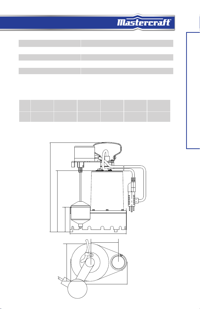
AUTOMATIC FLOAT SWITCH SPECIFICATIONS
Type Vertical with piggy-back plug
Switch on point* (factory set) 6” (15.24 cm)
Switch off point* (factory set) 2” (5.08 cm)
Material Polypropylene
Cord Length 10’ (3.05 m)
Cord Type SJOW, UL listed, 2-wire, 18 gauge
*Adjustable by changing tether length
PERFORMANCE CHART
Lift 0’
(0 m)
Flow 2760 U.S. GPH
(10,448 L/Hr)
*Friction loss in piping not included in measurement
5’
(1.5 m)
2160 U.S. GPH
(8,176 L/Hr)
10’
(3 m)
1800 U.S. GPH
(6,813 L/Hr)
15’
(4.6 m)
1500 U.S. GPH
(5,678 L/Hr)
20’
(6 m)
720 U.S. GPH
(2,725 L/Hr)
DIMENSIONS
5
25’
(7.6 m)
60 U.S. GPH
(227 L/Hr)
TECHNICAL SPECIFICATIONS
310 mm
12 3/16”
8 3/8”
214 mm
3 1/2”
89 mm
6”
152 mm
7 3/4”
197 mm
100 mm
7 3/4”
197 mm
3 7/8”
Page 6
headline bars
headline bars
6
model no. 062-3404-4 | contact us: 1-800-689-9928
SAFETY GUIDELINES
Carefully read, understand and follow all safety instructions in this manual. This
is the safety alert symbol. When you see this symbol, look for one of the following signal
words.
Indicates a hazardous situation which, if not avoided, will result in death or
serious injury.
Indicates a hazardous situation which, if not avoided, could result in death or
serious injury.
Indicates a hazardous situation which, if not avoided, could result in minor or
moderate injury.
Indicates important information, that if not followed, may result in damage to
the equipment.
Safety Information
Read these warnings carefully. Know the application and limitations of this pump. Failure to
follow these warnings could result in serious bodily injury and/or property damage.
RISK OF ELECTRIC SHOCK. Disconnect and lockout power supply before
SAFETY GUIDELINES
removing old pump or installing or servicing this pump.
RISK OF ELECTRIC SHOCK. This pump is supplied with a grounding
conductor and grounding type attachment plug. To reduce the risk of electric
shock, be certain that it is connected only to a properly grounded, grounding type receptacle.
For added safety, it is highly recommended to connect this pump to a GFCI (Ground Fault Circuit
Interrupter) outlet. Connect only to a receptacle that is adequately rated for the voltage and
amperage of this pump.
The installation of this pump must be in accordance with the Canadian
Electrical Code (CE code), National Plumbing Code of Canada (NPC),
International Plumbing Code (IPC) as well as all applicable local codes and ordinances.
Do not install this pump in any location classified as hazardous by the
Canadian Electrical Code (CE code)
Do not use this pump to pump flammable or explosive fluids such as gasoline,
kerosene, etc. Do not use this pump in flammable or explosive environments.
Use only with liquids compatible with pump component materials.
RISK OF ELECTRIC SHOCK. This pump has not been investigated for use in
swimming pool or marine areas.
RISK OF ELECTRIC SHOCK. DO NOT use the power cord to remove or lower
the pump into the basin. The cord may pull apart exposing bare wires which
could cause a fire or electrical shock. Use the handle supplied with the pump for installing and
removing the pump from the basin.
Do not run the pump dry. This pump relies on water for cooling. Running the
pump dry can cause the pump to overheat and the possibility of burns to
anyone that handles the pump. Running the pump dry will void the warranty.
Do not use this pump for potable/drinking water. Use only in applications for
which the pump is designed.
Do not expose pump to freezing temperatures. Discharge lines exposed to
freezing temperatures should be positioned with a downward slope to prevent
freezing.
Page 7
SAFETY GUIDELINES (CONTINUED)
DO NOT UNDER ANY CIRCUMSTANCES REMOVE THE GROUND PIN. The
3-prong plug must be inserted into a mating 3-prong grounded receptacle.
If the installation does not have such a receptacle, it must be changed to the proper type, wired
and grounded in accordance with the Canadian Electrical Code and all applicable local codes and
ordinances.
All wiring must be performed by a qualified electrician.
Keep hands clear of suction and discharge openings. To prevent injury, never
insert fingers into pump while it is plugged in.
Sump basins must be vented according to local plumbing codes.
Do not handle this pump with wet hands or while standing on wet or damp
surfaces or in water.
If a flexible discharge hose is used, make sure the pump is secured in the
basin to prevent movement. Failure to secure the pump could result in
flooding from switch malfunction.
This pump motor is equipped with an automatic resetting thermal protector
and may restart unexpectedly.
Please read this before installing or operating pump. This information is provided for your
SAFETY and to PREVENT EQUIPMENT PROBLEMS. Most accidents can be avoided by using COMMON SENSE.ts.
• Always wear appropriate safety gear, such as safety glasses, when working on the pump
or piping.
• Only qualified personnel should install, operate, and repair pump.
• Make sure lifting handle is securely fastened each time before lifting.
• Do not lift pump by the power cord.
• Do not exceed manufacturer’s recommendation for maximum performance, as this could cause the
motor to overheat.
• Secure the pump in its operating position so it cannot tip over, fall, or slide.
• Keep hands and feet away from impeller when power is connected.
• Any wiring of pumps should be performed by a qualified electrician.
• Cable should be protected at all times to avoid punctures, cuts, and abrasions. Inspect frequently.
• Do not remove cord and strain relief.
• Mastercraft® Canada is not responsible for losses, injury, or death resulting from a failure to observe
these safety precautions, or misuse or abuse of pumps or equipment.
7
SAFETY GUIDELINES
CAUTION!
• Do not wear loose clothing that may become entangled in the impeller or other moving parts.
• Pumps generate heat and pressure during operation. Allow time for pumps to cool before handling or servicing.
• Keep clear of suction and discharge openings. Do not insert fingers in pump with power connected.
• Never operate a pump with a power cord that has frayed or brittle insulation.
WARNING!
• To reduce risk of electric shock, all wiring and junction connections should be made per the Canadian Electrical Code
(CEC) and applicable provincial and local codes. Requirements may vary depending on usage and location.
• To reduce risk of electric shock, always disconnect the pump from the power source before handling or servicing.
Page 8
headline bars
headline bars
8
model no. 062-3404-4 | contact us: 1-800-689-9928
UNPACKING
• Upon receiving the pump, it should be inspected for damage or missing parts. If you have
concerns please contact customer support at 1-800-689-9928.
REMOVING OLD PUMP (IF NECESSARY)
1. Remove the old pump from the basin. If you need to cut the old discharge pipe to remove
the pump, cut it as close to floor level as possible. If a check valve is attached to the pump,
be prepared for water to leak from the pipe. Allow water to drain into the sump basin.
2. Inspect the basin for accumulated mud, sand, silt or small stones. Clean out the basin if
necessary.
INSTALL NEW PUMP
1. Connect the discharge pipe to the pump discharge. Do not use pipe joint compound on
plastic pipe or plastic pump threads as this can degrade the plastic. Use non-stick tape if
necessary.
2. Install a full flow, swing type check valve (sold separately) either directly into the pump
discharge or on the discharge pipe. Make sure the check valve is positioned in the correct
INSTALLATION INSTRUCTIONS
direction of flow.
3. Place the pump on a solid, level surface in the basin. Use bricks or blocks to raise the
pump off the bottom surface. Do not place the pump directly in mud, sand, silt or on rocky
surfaces as these materials can clog or damage the pump. Do not lower the pump into the
basin by the power cord or discharge pipe; use the attached handle.
4. Position the pump in the basin making sure that the float switch will operate freely without
coming in contact with the sides of the basin.
5. Once the pump is positioned in the basin, mark and cut your existing discharge pipe to
fit the height of the pump or continue installation of discharge pipe to the outside of the
building.
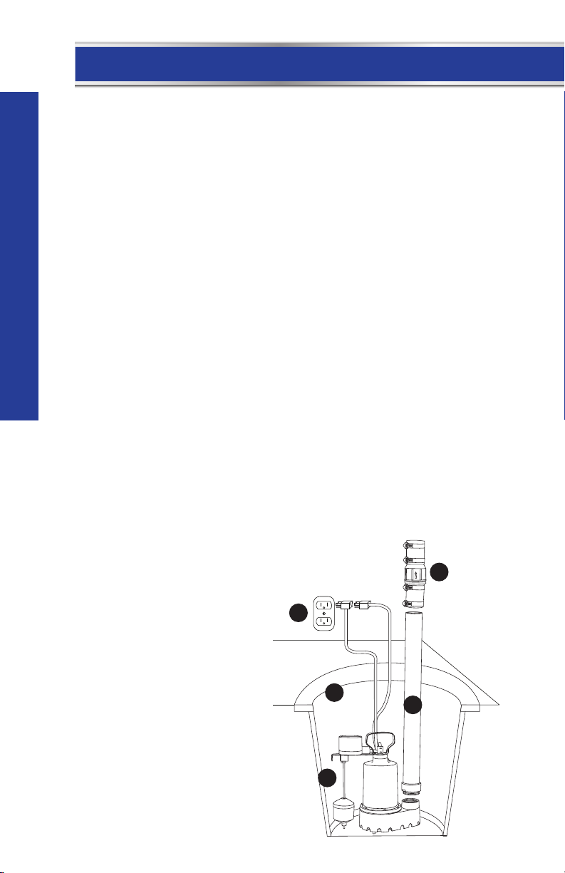
INSTALLATION DIAGRAM
A. Grounded outlet. A
GFCI outlet is strongly
recommended.
B. Discharge pipe
C. Full-flow swing type check
valve
D. Sump basin
E. Position pump so the float
switch operates freely
without touching the sides
of the basin.
C
A
D
B
E
Page 9

OPERATION
1. See Figure 2 for pump plug-in instructions.
• Automatic: Plug the piggy-back plug of the float
switch into a 115 V grounded outlet. The use of a
GFCI is strongly recommended. Plug the pump plug
into the back of the piggy-back float switch plug.
• Manual: Plug the pump plug into a 115 V grounded
outlet. The use of a GFCI is strongly recommended.
2. Test your installation by filling the basin with water. Observe the float switch through at least
one complete cycle to ensure it operates freely and does not contact the sides of the basin. If
necessary, adjust the float switch or reposition the pump to ensure proper operation.
3. This pump is equipped with an anti-airlock hole. A stream of water will emit from this hole
when the pump is operating. This is a normal feature of this pump. The anti-airlock hole
should be cleaned periodically to prevent the pump from becoming air-locked.
4. Do not let the pump run dry. The pump depends on water for cooling and lubrication.
Operating the pump without water may cause the motor to overheat or cause damage to
internal parts. It may also shorten the life of your pump.
5. Your pump motor is thermally protected. It is not recommended for pumping liquids over
120°F (49°C). The thermal overload protector will automatically shut down the pump in an
overheat situation. The pump will reset itself once the pump cools down. This overload is
designed as a safety device and it will fail after repeated use. Normal operation is for fluids
between 32 and 120°F (0 and 49°C).
Risk of electric shock. Always disconnect the power supply before attempting
to install, service or perform maintenance on the pump.
All repairs must be made by an authorized service centre.
This submersible pump contains oil which may become pressurized and hot
under normal operating conditions – allow the pump to cool for 2–3 hours
before servicing.
FIGURE 2
AUTOMATIC
MANUAL
MAINTENANCE
1. The pump motor is hermetically sealed in the housing and does not require any service.
Disassembly of the motor housing or modification of the power cord voids the warranty.
2. Periodically check the sump basin for accumulation of mud, silt, sand and foreign objects. Clean
the basin as needed to prevent damage or clogging of the pump.
3. Periodically check the removable intake screen for obstructions. Clean if necessary.
4. Periodically inspect and clean the anti-airlock hole.
5. Inspect the float switch for any accumulated debris that may inhibit it from operating properly.
Clean if necessary.
6. Inspect the impeller for signs of wear and obstructions.
7. Inspect the power cord for signs of damage or wear. Do not operate the pump if the cord is
damaged or worn.
8. In applications where the pump may not activate for extended periods of time, it is recommended
to cycle the pump at least once per month to ensure the pumping system is working properly when
needed.
9
OPERATION AND MAINTENANCE
Page 10

headline bars
10
headline bars
model no. 062-3404-4 | contact us: 1-800-689-9928
PARTS LIST
No. Description Qty.
1 Power Cord 1
2 Handle 1
3
4 Float Switch 1
5 Shaft Seal 1
6 Impeller 1
7 Gasket 1
8 Base / Volute 1
9 Intake Screen 1
10 Motor 1
11 Float Switch
KEY PARTS DIAGRAM
*If motor fails, replace
entire pump.
Oil Fill Plug
with O-Ring
Bracket
11
1
1
2
3
1
4
10
*
5
6
7
8
9
Page 11

TROUBLESHOOTING
Problem Possible Causes Solution
The pump does not
start or run.
The pump starts and
stops too often.
The pump runs but
moves little or no
water.
Pump is not plugged in, switch or
breaker is off.
Check for blown fuses or tripped
circuit breakers or tripped GFCI
outlets.
Float switch is defective.
Motor thermal protector tripped.
Float is stuck or obstructed. Remove obstruction or position the pump so it
Backflow of water from discharge
hose/pipe.
Float switch is defective. Replace float switch.
Clogged discharge hose/pipe. Remove clog.
Frozen discharge hose/pipe. Allow hose/pipe to thaw.
Pump is air locked. Check airlock hole for clogs and clean if
Low line voltage. Check wire size and increase if necessary.
Check valve is stuck in the closed
position.
Check valve is installed backwards. Make sure valve is installed in the correct
Worn, damaged or clogged pump
parts.
Discharge head exceeds pump
capacity.
Plug pump in or turn on switch/breaker.
Replace fuse, reset breaker, reset GFCI outlet.
Check and replace if necessary.
Allow pump to cool. Pump will reset
automatically.
will not become stuck.
Install or replace check valve.
necessary.
Inspect, repair or replace if necessary.
direction of flow.
Inspect for wear, damage or clog and clean or
replace if necessary.
See performance chart for pump limitations,
see page 5.
11
TROUBLESHOOTING
Pump does not
shut off.
Float is obstructed or stuck. Remove obstruction.
Pump plug is not plugged into piggy-
back float switch plug.
Defective switch. Replace float switch.
Plug pump plug into float switch plug for
automatic operation. See page 9.
NOTE: Not all problems and corrections will apply to each pump. model.
CAUTION!
• Always disconnect the pump from the electrical power source before handling. If the system fails to operate
properly, carefully read instructions and perform maintenance recommendations. If operating problems persist, the
troubleshooting chart above may be of assistance in identifying and correcting them.
Page 12

headline bars
12
WARRANTY INFORMATION
This Mastercraft product is guaranteed for a period of three (3) years from the date of original retail
purchase against defects in materials and workmanship.
Subject to the conditions and limitations described below, this product, if returned to us with proof of purchase
within the stated warranty period and if covered under this warranty, will be repaired or replaced (with the same
model, or one of equal value or specification), at our option. We will bear the cost of any repair or replacement and
any costs of labour relating thereto.
These warranties are subject to the following conditions and limitations:
a. A bill of sale verifying the purchase and purchase date must be provided;
b. This warranty will not apply to any product or part thereof which is worn or broken or which has become
inoperative due to abuse, misuse, accidental damage, neglect or lack of proper installation, operation or
maintenance (as outlined in the applicable owner’s manual or operating instructions) or which is being used
for industrial, professional, commercial or rental purposes;
c. This warranty will not apply to normal wear and tear or to expendable parts or accessories that may be
supplied with the product which are expected to become inoperative or unusable after a reasonable period
of use;
d. This warranty will not apply to routine maintenance and consumable items such as, but not limited to, fuel,
lubricants, vacuum bags, blades, belts, sandpaper, bits, fluids, tune-ups or adjustments;
e. This warranty will not apply where damage is caused by repairs made or attempted by others (i.e., persons
not authorized by the manufacturer);
f. This warranty will not apply to any product that was sold to the original purchaser as a reconditioned or
refurbished product (unless otherwise specified in writing);
g. This warranty will not apply to any product or part thereof if any part from another manufacturer is installed
therein or any repairs or alterations have been made or attempted by unauthorized persons;
h. This warranty will not apply to normal deterioration of the exterior finish, such as, but not limited to,
scratches, dents, paint chips, or to any corrosion or discolouring by heat, abrasive and chemical cleaners;
and
i. This warranty will not apply to component parts sold by and identified as the product of another company,
which shall be covered under the product manufacturer’s warranty, if any.
Additional Limitations
This warranty applies only to the original purchaser and may not be transferred. Neither the retailer nor the
manufacturer shall be liable for any other expense, loss or damage, including, without limitation, any indirect,
incidental, consequential or exemplary damages arising in connection with the sale, use or inability to use this
product.
Notice to Consumer
This warranty gives you specific legal rights, and you may have other rights, which may vary from province to
province. The provisions contained in this warranty are not intended to limit, modify, take away from, disclaim or
exclude any statutory warranties set forth in any applicable provincial or federal legislation.
Page 13

N° de modèle : 062-3404-4
R
POMPE DE VIDANGE
Immergée
IMPORTANT :
Veuillez lire ce guide attentivement avant de
procéder à l’installation ou à l’utilisation de cette
pompe. Conservez ce guide pour toute consultation
ultérieure.
GUIDE
D’UTILISATION
Page 14

headline bars
Page 15

TABLE DES MATIÈRES
Fiche technique 4
Consignes de sécurité 6
Instructions d'installation 8
Fonctionnement et entretien 9
Schéma des pièces clés 10
Dépannage 11
Garantie 12
15
TABLE DES MATIÈRES
REMARQUE :
Si des pièces sont manquantes ou endommagées, ou si vous avez des questions,
veuillez appeler notre service d’assistance téléphonique sans frais au 1 800 689-
9928.
CONSERVEZ CES CONSIGNES
Le présent guide d’utilisation contient un mode d’emploi et des consignes de sécurité
importants. Lisez et respectez toutes les instructions lorsque vous utilisez ce produit.
Page 16

headline bars
headline bars
16
N° de modèle : 062-3404-4 | Communiquez avec nous au 1 800 689-9928
FICHE TECHNIQUE DU MOTEUR
Puissance 1/3 HP
Tension 115 V
Ampères 4,1 A
hertz 60 Hz
Courant Monophasé
Tr/min 3 450
Type de moteur Condensateur auxiliaire permanent
Isolation Classe A
Exigences du circuit Circuit individuel de 15 A (min)
Cycle de travail Continu*
Joint d'arbre Carbone/céramique et acier inoxydable
Arbre du moteur Acier inoxydable
Palier supérieur du moteur Roulement à billes
Palier inférieur du moteur Roulement à billes
FICHE TECHNIQUE
Refroidissement Refroidissement à l'huile
Protection du moteur Circuit de protection thermique intégré à réinitialisation
*Pour assurer un fonctionnement continu, la profondeur d'eau doit être d'au moins 6 po (15, 24
cm) pour éviter toute surchauffe du moteur.
automatique
FICHE TECHNIQUE DE LA POMPE
Diamètre du raccord de refoulement 1 1/2 po (38,1 mm) à filetage femelle NPT
Longueur du cordon 10 pi (3 m)
Type de cordon SJTW, homologué UL, 3 fils, calibre 18
Boîtier de pompe Fonte
Pied de la pompe Fonte
Matériau de la tête de pompe Acier inoxydable
Type de tête de pompe Résistant au colmatage
Joint d'étanchéité Buna-N
Acceptant les matières solides Turbine d'un diamètre de 3/8 po (9,5 mm)
Températures des liquides 32 à 120 °F (0 à 49 °C)
Fonctionnement Automatique ou manuel
Dispositifs de fixation Acier inoxydable
Débit maximal 2 760 gal US/h (10 448 L/h)
Colonne d'eau maximale 25 pi (8 m)
Pression maximale 10,8 lb/po² (74,5 kPa)
Poids 17 lbs (7,71 kg)
Page 17

FICHE TECHNIQUE DU CONTACTEUR À FLOTTEUR CAPTIF
Type Interrupteur verticalet fiche à prise arrière intégrée.
Point d'activation (réglé en usine) 10 po (25,4 cm)
Point d'inactivation (réglé en usine) 2 po (5,08 cm)
Matériau Polypropylène
Longueur du cordon 10 pi (3 m)
Type de cordon SJOW, homologué UL, 2 fils, calibre 18
*Réglable en modifiant la longueur du contacteur
TABLEAU DE RENDEMENT
Hauteur de
refoulement
Débit 2 760 gal US/h
*La mesure ne tient pas compte de la perte de pression dans le tuyau
DIMENSIONS
0 pi
(0 m)
(10 448 L/h)
5 pi
(1,5 m)
2 160 gal US/h
(8 176 L/h)
10 pi
(3 m)
1 800 gal US/h
(6 813 L/h)
15 pi
(4,6 m)
1 500 gal US/h
(5 678 L/h)
20 pi
(6 m)
720 gal US/h
(2 725 L/h)
17
25 pi
(7,6 m)
60 gal US/h
(227 L/h)
FICHE TECHNIQUE
310 mm
12 3/16 po
214 mm
8 3/8 po
89 mm
3 1/2 po
6 po
152 mm
7 3/4 po
197 mm
3 7/8 po
100 mm
7 3/4 po
197 mm
Page 18

headline bars
headline bars
18
N° de modèle : 062-3404-4 | Communiquez avec nous au 1 800 689-9928
CONSIGNES DE SÉCURITÉ
Lisez attentivement, comprenez et suivez toutes les consignes de sécurité dans
ce guide. Ceci est un symbole d’avertissement. Lorsque vous apercevez ce symbole,
recherchez l’un des mots d’avertissement suivants.
Indique une situation dangereuse qui, si elle n’est pas évitée, entraînera la
mort ou des blessures graves.
Indique une situation dangereuse qui, si elle n’est pas évitée,
pourrait entraîner la mort ou des blessures graves.
Indique une situation dangereuse qui, si elle n’est pas évitée, pourrait
entraîner des blessures légères ou modérées.
Indique la présence de renseignements importants qui, s’ils ne sont pas suivis,
pourraient entraîner des dommages à l’équipement.
Consignes de sécurité
Lisez attentivement ces avertissements. Prenez connaissance des applications et des contraintes
de cette pompe. Le non-respect de ces avertissements pourrait entraîner des blessures
corporelles graves et/ou des dommages matériels.
RISQUE DE CHOC ÉLECTRIQUE. Coupez et verrouillez l’alimentation
CONSIGNES DE SÉCURITÉ
électrique avant de retirer une pompe usagée, d’en installer une neuve ou
d’effectuer toute tâche d’entretien.
RISQUE DE CHOC ÉLECTRIQUE. Cette pompe est munie d’un conducteur
de mise à la terre et d’une fiche de mise à la terre. Pour réduire le risque
de choc électrique, assurez-vous de brancher la pompe uniquement à une prise correctement
mise à la terre. Pour une sécurité accrue, nous vous recommandons fortement de brancher cette
pompe à une prise équipée d’un disjoncteur de fuite de terre. Branchez-la uniquement à une prise
adaptée à la tension et à l’intensité de cette pompe.
L’installation de cette pompe doit être conforme au Code
canadien de l’électricité, au Code national de plomberie du
Canada, au Code international de la plomberie et tous les autres codes et règlements municipaux
en vigueur.
N’installez pas cette pompe dans un endroit classé comme
dangereux par le Code canadien de l’électricité.
N’utilisez pas cette pompe pour l’aspiration de substances inflammables
ou explosives, comme l’essence, le kérosène, etc. N’utilisez pas la pompe
dans des milieux inflammables et explosifs. N’utilisez la pompe qu’avec des liquides compatibles
avec les matériaux de ses composants.
RISQUE DE CHOC ÉLECTRIQUE. Cette pompe n’a pas été
conçue pour une utilisation dans les piscines ou les zones
maritimes.
RISQUE DE CHOC ÉLECTRIQUE. N’utilisez PAS le cordon
d’alimentation pour monter ou descendre la pompe dans le
bassin. Le cordon pourrait se déchirer, exposant ainsi des fils nus qui pourraient poser un risque
d’incendie ou de décharge électrique. Utilisez la poignée fournie avec la pompe lorsque vous
montez et descendez la pompe du bassin.
Ne faites pas tourner la pompe à sec. Cette pompe emploie
de l’eau pour le refroidissement. Faire tourner la pompe à sec
pourrait causer sa surchauffe et un risque de brûlure pour toute personne qui la manipule. Faire
tourner la pompe à sec annulera sa garantie.
Page 19

CONSIGNES DE SÉCURITÉ (SUITE)
N’utilisez pas cette pompe pour aspirer de l’eau potable. Utilisez-la
uniquement aux fins prévues.
N’exposez pas la pompe au point de congélation. Les tuyaux
de refoulement exposés au point de congélation doivent être
positionnés vers le bas pour prévenir toute congélation.
VOUS NE DEVEZ JAMAIS, SOUS AUCUN PRÉTEXTE, RETIRER
LA BROCHE DE MISE À LA TERRE. La fiche à 3 broches doit être
insérée dans une prise mise à la terre correspondante à 3 fentes. Si vous ne possédez pas ce type
de prise, vous devez la remplacer par une prise adéquate, câblée et mise à la terre conformément
au Code canadien de l’électricité et tout autre code municipal en vigueur.
Tout le câblage doit être effectué par un électricien qualifié.
Tenez vos mains à l’écart des orifices d’aspiration et de
refoulement. Pour prévenir les blessures, n’insérez jamais vos
doigts dans la pompe lorsqu’elle est branchée.
Ne manipulez pas cette pompe avec des mains mouillées ou
lorsque vous avez les pieds sur des surfaces mouillées ou
humides ou dans l’eau.
Si vous utilisez un tuyau de refoulement flexible, assurez-vous
de bien raccorder la pompe au bassin pour éviter que la pompe
se déplace. Le non-respect de cette consigne pourrait entraîner une inondation causée par une
anomalie du contacteur.
Le moteur de cette pompe est muni d’un circuit de protection thermique
intégré à réinitialisation automatique et pourrait redémarrer inopinément.
Veuillez lire les consignes suivantes avant de procéder à l’installation ou à l’utilisation de la pompe.
Ces renseignements sont fournis pour votre sécurité et pour ÉVITER LES PROBLÈMES D’ÉQUIPEMENT. La plupart
des accidents peuvent être évités en utilisant le BON SENS.
• Portez toujours de l’équipement de sécurité adéquat, comme des lunettes de sécurité, lorsque vous travaillez
avec la pompe ou de la tuyauterie.
• Seules les personnes qualifiées sont autorisées à installer, utiliser et réparer la pompe.
• Assurez-vous, en tout temps, que la poignée de transport est bien fixée avant de soulever l’appareil.
• Ne soulevez pas la pompe par le cordon d’alimentation.
• N’excédez pas le rendement maximal recommandé par le fabricant, car cela pourrait causer la surchauffe du
moteur.
• Fixez la pompe dans sa position de travail de sorte qu’elle ne puisse basculer, chuter ou glisser.
• Tenez les mains et les pieds à l’écart de la tête de pompe lorsque l’appareil est branché.
• Tout câblage de pompe doit être effectué par un électricien qualifié.
• Les câbles doivent être protégés en tout temps pour éviter les perforations, les coupures et l’abrasion.
Examinez l’appareil régulièrement.
• Ne retirez pas le cordon ou le serre-câble.
• MastercraftMD Canada ne peut pas être tenue responsable des dommages, blessures ou de la mort découlant
du non-respect de ces consignes, ou d’une utilisation inadéquate ou abusive de pompes et d’équipement.
19
CONSIGNES DE SÉCURITÉ
ATTENTION!
• Ne portez pas des vêtements amples qui risquent de se prendre dans la tête de pompe ou d’autres pièces mobiles.
• Les pompes produisent de la chaleur et de la pression durant leur utilisation. Laissez les pompes refroidir avant de les
manipuler ou d’effectuer toute tâche d’entretien.
• Restez à l’écart des orifices d’aspiration et de refoulement. N’insérez jamais vos doigts dans la pompe lorsqu’elle est
branchée.
• N’utilisez jamais une pompe munie d’un cordon d’alimentation dont l’isolation est dénudée ou se détériore.
AVERTISSEMENT!
• Pour réduire le risque de choc électrique, tout le câblage et tous les raccordements de jonction doivent être effectués
conformément au Code canadien de l’électricité et tous les autres codes provinciaux et municipaux en vigueur. Les
exigences peuvent varier selon l’usage et l’emplacement.
• Pour réduire le risque de choc électrique, débranchez toujours la pompe de la source d’alimentation avant de manipuler
l’appareil ou d’effectuer toute tâche d’entretien.
Page 20

headline bars
headline bars
20
CONSIGNES D’INSTALLATION
N° de modèle : 062-3404-4 | Communiquez avec nous au 1 800 689-9928
DÉBALLAGE
• Lorsque vous recevez la pompe, examinez-la pour repérer tout dommage ou toute pièce
manquante. Pour toute question, veuillez communiquer avec le service à la clientèle en
composant le 1 800 689-9928.
RETRAIT D’UNE POMPE USÉE (AU BESOIN)
1. Retirez la pompe usée du bassin. Si vous avez besoin de couper l’ancien tuyau de
refoulement pour retirer la pompe, coupez-le le plus près du plancher que possible. Si un
clapet de non-retour est raccordé à la pompe, de l’eau coulera du tuyau. Laisser l’eau couler
dans le bassin.
2. Examinez le bassin pour toute accumulation de boue, de sable, de limon et de cailloux.
Nettoyez le bassin, au besoin.
INSTALLATION D’UNE POMPE NEUVE
1. Raccordez le tuyau de refoulement à l’orifice de refoulement de la pompe. N’utilisez pas un
composé de scellement sur les joints filetés en plastique du tuyau ou de la pompe car cela
causera sa dégradation. Utilisez du ruban pour joints filetés, au besoin.
2. Raccordez un clapet de non-retour à battant de plein débit (vendu séparément) soit
directement à l’orifice de refoulement de la pompe ou au tuyau de refoulement. Assurezvous de raccorder le clapet de non-retour dans le bon sens, en suivant le flux.
3. Placez la pompe sur une surface plane et solide dans le bassin. Utilisez des briques ou des
blocs pour surélever la pompe du fond du bassin. Ne placez pas la pompe directement dans
la boue, le sable, le limon, ou sur toute surface rocheuse, car ces matières peuvent colmater
et endommager la pompe. Ne descendez pas la pompe dans le bassin à l’aide du cordon
d’alimentation ou du tuyau de refoulement; utilisez la poignée fournie.
4. Placez la pompe dans le bassin en vous assurant que le flotteur puisse monter et descendre
librement sans toucher les parois du bassin.
5. Une fois que la pompe est positionnée dans le bassin, marquez et coupez votre tuyau de
refoulement actuel de sorte qu’il corresponde à la hauteur de la pompe ou installez le tuyau
de refoulement en l’orientant vers l’extérieur de l’immeuble.
SCHÉMA D’INSTALLATION
A. Prise de mise à la terre.
Nous vous recommandons
fortement d’utiliser un
disjoncteur de fuite de terre.
B. Tuyau de refoulement
C. Clapet de non-retour à
battant de plein débit
D. Bassin de puisard
E. Positionnez la pompe de
sorte que le contacteur à
flotteur monte et descende
sans toucher les parois du
bassin.
C
A
D
B
E
Page 21

FONCTIONNEMENT
• Consultez la Figure 2 pour les consignes relatives au
branchement de la pompe.
• Automatique : Branchez la fiche à prise arrière
intégrée du contacteur à flotteur à une prise mise à la
terre de 115 V. Nous vous recommandons fortement
d’utiliser un disjoncteur de fuite de terre. Branchez la
fiche de la pompe au dos de la fiche à prise arrière
intégrée.
• Manuel : Branchez la fiche de la pompe à une prise mise à la terre de 115 V. Nous vous
recommandons fortement d’utiliser un disjoncteur de fuite de terre.
2. Testez l’installation en remplissant le bassin avec de l’eau. Observez le contacteur à flotteur
pendant un cycle complet pour vous assurer qu’il monte et descend librement et ne touche
pas aux parois du bassin. Réglez le contacteur à flotteur ou repositionnez la pompe pour
assurer un fonctionnement adéquat, au besoin.
3. Cette pompe est munie d’un trou d’échappement. Un jet d’eau sortira de ce trou lorsque la
pompe est en marche. Ceci est une caractéristique normale. Le trou d’échappement doit être
nettoyé régulièrement pour éviter que la pompe se verrouille.
4. Ne faites pas tourner la pompe à sec. Cette pompe emploie de l’eau pour le refroidissement
et la lubrification. Faire tourner la pompe à sec pourrait causer sa surchauffe et endommager
des pièces internes. Ceci pourrait aussi réduire la durée de vie de votre pompe.
5. Le moteur de la pompe est muni d’une protection thermique. Nous vous déconseillons de
procéder à l’aspiration de liquides d’une température supérieure à 120 °F (49 °C). Le circuit
de protection thermique arrêtera la pompe automatiquement si cette dernière surchauffe.
Elle se réinitialisera après le refroidissement. Le circuit de protection thermique est un
dispositif de sécurité qui cessera de fonctionner si utilisé à répétition. En temps normal, la
pompe peut être utilisée pour aspirer des liquides d’une température entre 32 et 120 °F (0 et
49 °C).
FIGURE 2
AUTOMATIQUE
MANUEL
21
FONCTIONNEMENT ET ENTRETIEN
Risque de choc électrique. Débranchez toujours la source d’alimentation
avant d’installer la pompe ou d’effectuer des réparations ou des tâches
d’entretien.
Toutes les réparations doivent être effectuées dans un centre de
service autorisé.
Cette pompe immergée contient de l’huile qui pourrait devenir chaude et
sous pression dans des conditions de fonctionnement normal – Laissez la
pompe se refroidir 2 à 3 heures avant d’effectuer toute tâche d’entretien.
ENTRETIEN
1. Le moteur de la pompe est scellé hermétiquement dans le boîtier et ne nécessite aucun entretien.
Tout démontage du boîtier du moteur ou toute modification apportée au cordon d’alimentation
annulera la garantie.
2. Examinez régulièrement le bassin pour toute accumulation de boue, de limon, de sable et de corps
étrangers. Nettoyez le bassin, au besoin, pour prévenir tout dommage ou colmatage de la pompe.
3. Examinez régulièrement la crépine d’aspiration pour toute obstruction. Nettoyez-la au besoin.
4. Examinez et nettoyez le trou d’échappement régulièrement.
5. Examinez le contacteur à flotteur pour toute accumulation de débris qui pourrait empêcher la pompe
de fonctionner adéquatement. Nettoyez-la au besoin.
6. Examinez la tête de pompe pour toute trace d’usure et d’obstruction.
7. Examinez le cordon d’alimentation pour toute trace d’endommagement ou d’usure. N’utilisez pas la
pompe si le cordon d’alimentation est endommagé ou usé.
8. Lorsque vous n’utilisez pas la pompe pendant des périodes prolongées, nous vous recommandons
d’utiliser la pompe au moins une fois par mois pour assurer l’efficacité du système d’aspiration.
Page 22

headline bars
22
headline bars
N° de modèle : 062-3404-4 | Communiquez avec nous au 1 800 689-9928
LISTE DES PIÈCES
N° Description Qté
1 Cordon
d’alimentation
2 Guidon 1
3 Bouchon de
remplissage
d'huile avec
joint torique
4 Contacteur à
flotteur
5 Joint de
l’arbre
6 Tête de
pompe
SCHÉMA DES PIÈCES CLÉS
7 Joint
d'étanchéité
8 Base/sortie 1
9 Crépine
d'aspiration
10 Moteur 1
11 Support
D’interrupteur
à Flotteur
*Si le moteur ne
fonctionne pas, remplacez
complètement la pompe.
1
1
1
1
1
1
1
1
11
1
2
4
5
6
3
10
*
7
8
9
Page 23

DÉPANNAGE
Problème Causes possibles Solution
La pompe ne
démarre pas ou ne
fonctionne pas.
La pompe démarre
et s’arrête trop
fréquemment.
La pompe fonctionne
mais n’aspire que
de petites quantités
d’eau ou pas d’eau
du tout.
La pompe ne
s’éteint pas.
La pompe n'est pas branchée.
L'interrupteur ou le disjoncteur
est éteint.
Repérez tout fusible grillé,
tout disjoncteur et toute prise
à disjoncteur de fuite de terre
déclenchés.
Le contacteur à flotteur est
défectueux.
Le circuit de protection thermique
s'est déclenché.
Le flotteur est coincé ou obstrué. Éliminez l'obstruction ou positionnez la pompe
Il y a un refoulement d'eau provenant
du tuyau/conduit de refoulement.
Le contacteur à flotteur est défectueux. Remplacez-le.
Le tuyau/conduit de refoulement est
bouché.
Le tuyau/conduit de refoulement est
gelé.
La pompe est étanche. Vérifiez le trou d'échappement pour tout
La tension est faible. Vérifiez le calibre du cordon et remplacez-le
Le clapet de non-retour est bloqué en
position fermée.
Le clapet de non-retour est posé à
l'envers.
Certaines pièces sont usées,
endommagées ou colmatées.
La hauteur de refoulement excède la
capacité de la pompe.
Le flotteur est coincé ou obstrué. Éliminez l'obstruction.
La fiche de la pompe n'est pas
branchée à la fiche à prise arrière
intégrée du contacteur à flotteur.
Contacteur défectueux. Remplacez-le.
Branchez la pompe et allumez l'interrupteur ou
le disjoncteur.
Remplacez le fusible, réinitialisez le disjoncteur
et réinitialisez la prise à disjoncteur de fuite
de terre.
Vérifiez et remplacez si nécessaire.
Laissez la pompe se refroidir. Elle se
réinitialisera automatiquement.
de sorte que le flotteur ne reste pas coincé.
Installez ou remplacez le clapet de non-retour.
Débouchez le tuyau/conduit.
Laissez le tuyau/conduit dégeler.
colmatage, puis nettoyez-le au besoin.
par un nouveau de calibre plus élevé, au
besoin.
Examinez, réparez et remplacez au besoin.
Assurez-vous de poser le clapet dans le bon
sens, en suivant le flux.
Inspectez l'appareil pour toute trace d'usure,
d'endommagement et de colmatage, puis
nettoyez ou remplacez la pièce, au besoin.
Consultez le tableau de rendement à la page 5
pour connaître les limites de la pompe.
Branchez la fiche de la pompe à la prise du
contacteur à flotteur pour un fonctionnement
automatique. Voir la page 9.
23
DÉPANNAGE
REMARQUE : Tous les problèmes et toutes les corrections ne s’appliqueront pas nécessairement à votre pompe.model.
ATTENTION!
• Débranchez toujours la pompe de la source d’alimentation électrique avant de la manipuler. Si le système ne
fonctionne pas correctement, lisez attentivement les consignes et effectuez des recommandations d’entretien.
Si les problèmes de fonctionnement persistent, le tableau de dépannage ci-dessus peut vous aider à les
identifier et à les corriger.
Page 24

headline bars
24
GARANTIE
Le présent produit Mastercraft est garanti pour une période de trois (3) ans à compter de la date de
l’achat au détail original contre les vices de matériau(x) et de fabrication.
Sous réserve des conditions et restrictions énoncées ci-dessous, le présent produit sera réparé ou remplacé (par
un produit du même modèle ou par un produit ayant une valeur égale ou des caractéristiques identiques), à notre
discrétion, pourvu qu’il nous soit retourné avec une preuve d’achat à l’intérieur de la période de garantie prescrite
et qu’il soit couvert par la présente garantie. Nous assumerons le coût de tout remplacement ou réparation ainsi
que les frais de main-d’œuvre s’y rapportant.
La présente garantie est assujettie aux conditions et restrictions qui suivent:
a. Un contrat de vente attestant l’achat et la date d’achat doit être fourni;
b. La présente garantie ne s’applique à aucun produit ou pièce d’un produit qui est usé ou brisé, qui est devenu
hors d’usage en raison d’un emploi abusif ou inapproprié, d’un dommage accidentel, d’une négligence ou
d’une installation, d’une utilisation ou d’un entretien inapproprié (selon la description figurant dans le guide
d’utilisation ou le mode d’emploi applicable) ou qui est utilisé à des fins industrielles, professionnelles,
commerciales ou locatives;
c. La présente garantie ne s’applique pas à l’usure normale ou aux pièces ou accessoires non réutilisables qui
sont fournis avec le produit et qui deviendront vraisemblablement inutilisables ou hors d’usage après une
période d’utilisation raisonnable;
d. La présente garantie ne s’applique pas à l’entretien régulier et aux articles de consommation comme le
carburant, les lubrifiants, les sacs d’aspirateur, les lames, les courroies, le papier abrasif, les embouts, les
mises au point ou les réglages;
e. La présente garantie ne s’applique pas lorsque les dommages sont causés par des réparations ou des
tentatives de réparation faites par des tiers (c’est à dire des personnes non autorisées par le fabricant);
f. La présente garantie ne s’applique à aucun produit qui a été vendu à l’acheteur original à titre de produit
remis en état ou remis à neuf (à moins qu’il n’en soit prévu autrement par écrit);
g. La présente garantie ne s’applique à aucun produit ou pièce de produit lorsqu’une pièce d’un autre fabricant
est installée dans celui-ci ou que des réparations ou modifications ou tentatives de réparation ou de
modification ont été faites par des personnes non autorisées;
h. La présente garantie ne s’applique pas à la détérioration normale du fini extérieur, notamment les éraflures,
les bosses et les éclats de peinture, ou à la corrosion ou à la décoloration causée par la chaleur, les produits
abrasifs et les produits de nettoyage chimiques;
i. La présente garantie ne s’applique pas aux pièces vendues par une autre entreprise et décrites comme
telles, lesquelles pièces sont couvertes par la garantie du fabricant s’y rapportant, le cas échéant.
Restrictions supplémentaires
La présente garantie s’applique uniquement à l’acheteur original et ne peut être transférée. Ni le détaillant ni
le fabricant ne sont responsables des autres frais, pertes ou dommages, y compris les dommages indirects,
accessoires ou exemplaires liés à la vente ou à l’utilisation du présent produit ou à l’impossibilité de l’utiliser.
Avis au consommateur
La présente garantie vous accorde des droits précis et il se peut que vous ayez d’autres droits, lesquels peuvent
varier d’une province à l’autre. Les dispositions énoncées dans la présente garantie ne visent pas à modifier,
à restreindre, à éliminer, à rejeter ou à exclure les garanties énoncées dans les lois fédérales ou provinciales
applicables.
 Loading...