

Page 1
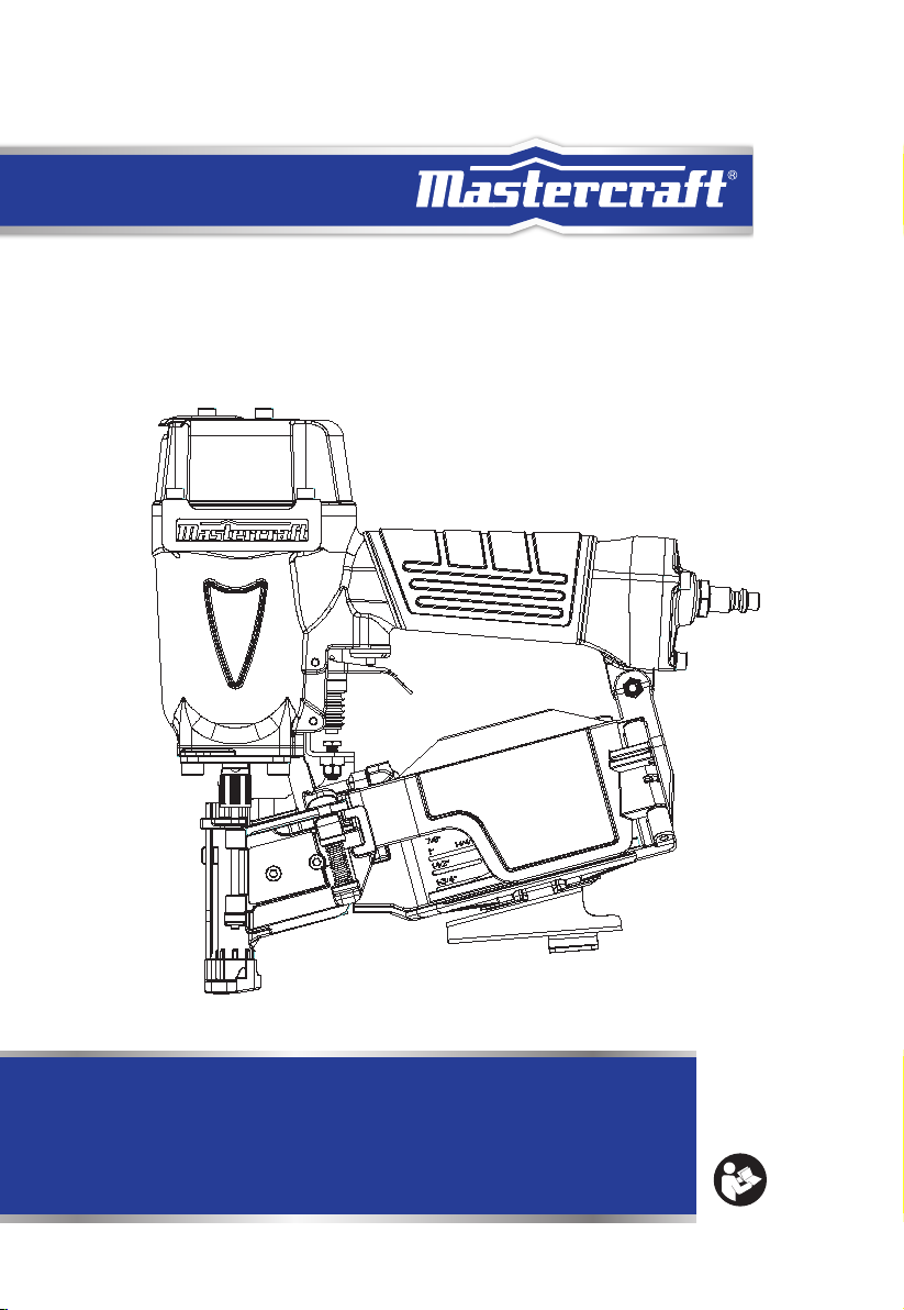
model no. 058-9816-0
AIR-POWERED
COIL ROOFING NAILER
IMPORTANT :
For your own safety, read and follow all of the Safety Guidelines
and Operating Instructions before operating this nailer. Keep this
manual for future reference.
OPERATING
MANUAL
Page 2

TABLE OF CONTENTS
3
TECHNICAL SPECIFICATIONS
SAFETY GUIDELINES
KEY PARTS DIAGRAM
TECHNICAL INFORMATION
TYPES OF NAILS
OPERATING INSTRUCTIONS
MAINTENANCE
TROUBLESHOOTING
EXPLODED VIEW
PARTS LIST
WARRANTY
10
13
14
21
24
26
27
28
4
5
9
TABLE OF CONTENTS
Page 3
model no. 058-9816-0 | contact us 1-800-689-9928
54
TECHNICAL SPECIFICATIONS
LOADING CAPACITY
FASTENER DETAILS
OPERATING PRESSURE
AIR CONSUMPTION
WEIGHT
AIR INLET
CF: Cubic Feet (the volumetric flow rate of air corrected to standardized conditions of
temperature and pressure).
NPT: National Pipe Thread.
120 Nails (1 coil)
15° Wire-collated coil nails (3/4 - 1 3/4")
70 - 110 PSI (4.8 - 7.5 bar)
0.043 CF/cycle @ 90 PSI
5 Ib 11 oz (2.58 kg)
3/8" NPT
TECHNICAL SPECIFICATIONS
SAFETY GUIDELINES
This manual contains information that relates to PROTECTING PERSONAL SAFETY and
PREVENTING EQUIPMENT PROBLEMS. It is very important to read this manual carefully and
understand it thoroughly before using the product. The symbols listed below are used to
indicate this information.
DANGER!
Potential hazard that will result in serious
injury or death.
WARNING!
Potential hazard that could result in
serious injury or death.
CAUTION!
Potential hazard that may result in
injury or damage to equipment.
PERSONAL SAFETY
These precautions are intended for the personal safety of the user and others working with the
user. Please take time to read and understand them.
Make sure you read and understand this manual before using this tool. Make sure other users
read and understand this manual before they use the tool.
SAFETY GUIDELINES
Note: The word “Note” is used to inform the readers of something
they need to know about the tool.
Page 4
model no. 058-9816-0 | contact us 1-800-689-9928
76
SAFETY GUIDELINES
Do not use oxygen or any other combustible or bottled
gas to power air-powered tools. Failure to observe this
warning can cause explosion and serious personal
injury or death. Use only compressed air to power
air-powered tools. Use a minimum of 25' (7.6 m) of
hose to connect the tool to only compressor. Failure to
comply will result in serious injury or death.
Risk of inhalation: Never directly inhale the air produced by the
compressor.
Risk of electric shock: Do not expose a compressor to rain.
Store it indoors. Disconnect the compressor from the power
source before servicing. The compressor must be grounded.
Do not use grounding adaptors.
Risk of personal injury: Do not direct compressed air from the air hose
SAFETY GUIDELINES
towards the user or other people or animal.
Never point nailer toward yourself or anyone else.
Always assume the nailer contains fasteners. Never point the nailer
toward yourself or anyone else, whether it contains fasteners or not.
If fasteners are mistakenly driven, it can lead to severe injuries.
Never engage in horseplay with the nailer. Respect the nailer as a
working implement.
DANGER!
Potential hazard that will result in serious injury or death.
Keep children away from the work area. Do not allow children to handle
power tools.
Do not use this tool in the presence of flammable liquids or gases. Sparks
that are created during use may ignite gases.
Do not point the tool towards yourself or other people, even when the tool
has stopped. Keep hands, feet, and all other parts of the body clear from
work area.
Do not attempt to clear nailer jams while the air hose is connected.
Do not keep the trigger or the safety stand pressed while loading nails.
Unintentional firing of a nail could cause serious personal injury or death.
Do not disconnect or reconnect the air hose with the trigger pressed. The
air-powered coil roofing nailer may fire when it is reconnected to the air
supply.
Risk of burns: The pump and the manifold generate high temperatures. In
order to avoid burns or other injuries, do not touch the pump, the manifold,
or the transfer tube while the compressor is running. Allow the parts to cool
down before handling or servicing. Keep children and pets away from the
compressor at all times.
Risk of bursting: Do not adjust the pressure switch or safety valve for any
reason. They have been preset at the factory for this compressor’s maximum
pressure. Tampering with the pressure switch or the safety valve may cause
personal injury or property damage.
Risk of bursting: Make sure the regulator is adjusted
so that the compressor outlet pressure is set lower
than the maximum operating pressure of the tool.
Before starting the compressor, pull the ring on the
safety valve to make sure the valve moves freely.
Drain water from the tank after each use. Do not weld
nor repair the tank. Relieve all pressure in the hose
before removing or attaching accessories.
SAFETY GUIDELINES
WARNING!
Do not allow inexperienced or untrained individuals to operate an airpowered coil roofing nailer or any other air-powered tool.
Keep hands and other parts of the body away from the firing head
during use. Keep hands, feet, and all other parts of the body at least
8" (20 cm) away from the firing head. Nails or objects in the
workpiece can cause serious injury if they are deflected by the
workpiece or if they are driven away from the point of entry.
Do not overload the tool. Allow the tool to operate at its optimum
speed for maximum efficiency.
Locate the compressor in a well-ventilated area for cooling, at a
minimum of 12" (30 cm) away from the nearest wall.
Protect the air hose and the power cord from damage and puncture.
Inspect them for weak or worn spots before every usage, and replace
them if necessary.
Always wear eye and hearing protection when using the air compressor. Failure to do so may result in hearing loss.
Do not carry the compressor while it is running.
Do not operate the compressor if it is not in a stable position.
Do not operate the compressor on a rooftop or in an elevated position
that could allow the unit to fall or be tipped over.
Always replace a damaged gauge before operating the unit again.
Page 5
model no. 058-9816-0 | contact us 1-800-689-9928
CAUTION!
Potential hazard that may result in injury or damage to
equipment.
Disconnect the tool from the air supply and turn off the
compressor before performing any maintenance,
loading or changing nails, when the tool is not in use,
when it is being handed to another person, and when it
is left unattended. Failure to comply may result in injury
or damage to equipment.
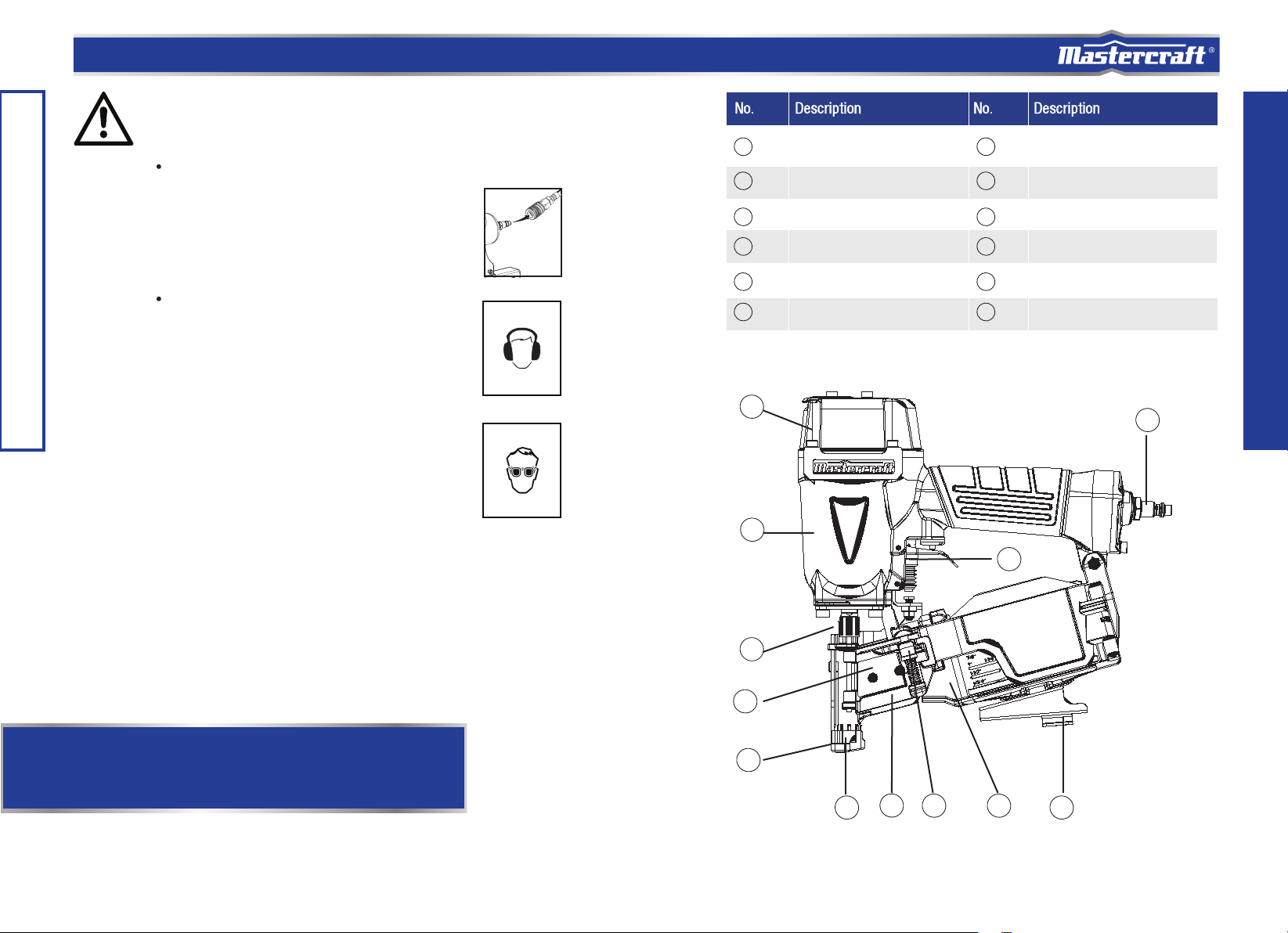
98
1
2
3
4
Exhaust Cover
Nose
Feeder
Push Lever
10
7
8
9
Knob
Magazine
Shingle Guide
Gun Body
Use safety goggles and ear protection:
Wear safety glasses with side shields when operating
the tool and verify that others in the work area are also
wearing safety glasses. Safety glasses must conform to
American National Standards Institute (ANSI Z87.1)
requirements and must provide protection from flying
particles from the front and the sides.
Air-powered tools are loud and the sound can cause
SAFETY GUIDELINES
hearing damage. Always wear ear protection to help
prevent hearing damage and loss. Failure to comply may
result in injury.
5
6
1
10
2
3
Outlet (Firing Head)
Nail Guide
11
12
12
Air plug
Trigger
11
KEY PARTS DIAGRAM
Note: Recycle unwanted materials rather than disposing of them as waste. Sort
the tools, hoses, and packaging in specific categories and take them to the local
recycling centre or dispose of them in an environmentally safe way.
4
6
5
7
8
9
Page 6

model no. 058-9816-0 | contact us 1-800-689-9928
model no. 058-9809-8 | contact us 1-800-689-9928
Compatible compressors
GUIDELINES FOR PROPER USE AND OPERATION
Be sure to use a proper air compressor with Mastercraft
should be able to supply a minimal air delivery of 4.7 CFM @ 90 PSI to ensure the compressor
can run continuously with the Mastercraft
®
Air-powered Coil Roofing Nailer.
®
air-powered tools. The compressor
General use
This Mastercraft® Air-powered Coil Roofing Nailer drives 3/4 to 1 3/4" wire-collated coil nails.
The tool is lightweight and durable, stands up to the elements and provides consistently
accurate results over the life of the tool. An ideal tool for a variety of construction projects,
including installation of asphalt roofing shingles and insulation boards, and features a
high-capacity side-load magazine, adjustable drive depth, durable construction, and more.
1110
Air Compressor
Size and Power
4–6 Gallons
8–11 Gallons
TECHNICAL INFORMATION
15+ Gallons
Wood Density
>0.6 g/cm
≤0.6 g/cm
3
3
1 1/2–2 HP 2 1/2 HP 3+ HP
Light-duty and
intermittent use
Light-duty and
intermittent use
Medium-duty and
intermittent use
Nail Size Compressor Air Pressure
<1" (25 mm)
≥1" (25 mm)
<1" (25 mm)
≥1" (25 mm)
Light-duty and
intermittent use
Medium-duty and
intermittent use
Heavy-duty and
continuous use
Light-duty and
intermittent use
Medium-duty and
intermittent use
Heavy-duty and
continuous use
90 PSI (6.3 bar)
120 PSI (8.3 bar)
75 PSI (5.2 bar)
110 PSI (7.5 bar)
Air-powered
MASTERCRAFT
Coil Roofing Nailer
Quick connector
Quick coupler
Air hose
Lubricator
®
Regulator (0 to 8.5 bar)
Filter
Cut-off valve
Air compressor
Air system
Always use clean, dry, regulated, compressed air at 4.8 to 7.5 bar (70 to 110 PSI).
Do not exceed the maximum or minimum pressures. Operating the tool at the wrong
pressure (too low or too high) will cause excessive noise or rapid wear.
WARNING!
Potential hazard that could result in serious injury or death.
Keep hands and other parts of the body away from the tool’s discharge
and working areas when connecting the air supply. Failure to comply
could lead to serious injury or death.
TECHNICAL INFORMATION
Page 7

model no. 058-9816-0 | contact us 1-800-689-9928
model no. 058-9809-8 | contact us 1-800-689-9928
1312
•
It is recommended that a filter-regulator-lubricator be used and be located as close to the tool
as possible.
•
If a filter-regulator-lubricator is not installed, place up to 6 drops of compressor oil into the air
inlet plug before each use.
•
If a filter-regulator-lubricator is installed, keep the air filter clean. A dirty filter will reduce the
air pressure to the tool, which will cause a reduction in power, efficiency, and general
performance.
•
For optimal performance, install a quick connector to the tool and a quick coupler on the
hose, if applicable.
•
Verify that all of the connections in the air supply system are sealed in order to prevent air
leakage.
Read this Instruction Manual carefully before using the air-powered roofing nailer.
• Read and follow all the safety instructions at the beginning of this manual. Inspect the
air-powered coil roofing nailer prior to each use in order to:
– ensure that the proper power source is being used.
– verify that the tool is in proper working order.
TECHNICAL INFORMATION
This Mastercraft® Air-powered Coil Roofing Nailer drives 3/4 to 1 3/4" wire-collated coil nails.
ACCEPTABLE NAILS
Length: 3/4 - 1 3/4"
1 3/4
"
(45 mm)
3/4"
(19 mm)
NAIL TYPE ICONS
These icons are used to select the proper nails for this specific nailer.
TYPES OF NAILS
WARNING!
Potential hazard that could result in serious injury or death.
• Do not use the tool if it is not in proper working order.
• Do not use oxygen or any other combustible or bottled gas to
power this tool.
• Do not use this tool in the presence of any flammable liquids or
gases.
• Keep hands and other parts of the body away from the firing
head during use.
• Do not point the tool towards the operator or other people.
• Do not attempt to clear a jammed nail when the air hose is
connected.
• Do not drive a nail on top of an existing nail. Failure to comply
could lead to serious injury or loss of life.
Note: Icons are colour coded. Please refer to the actual tool for the
specific colour.
WARNING!
Potential hazard that could result in serious injury or death.
• The use of any other types of nails will cause the nailer to
jam and could lead to serious injury or death.
Page 8

14
model no. 058-9816-0 | contact us 1-800-689-9928
model no. 058-9338 | contact us 1-800-689-9928
15
Loading nails
1. Disconnect the tool (1) from the air
supply (2) (Fig. A).
Fig. B
Knob
Nail guide
Magazine cover
2. Grip the nail guide and knob with finger.
Press the knob down, swing the nail
guide open and open the magazine cover
(Fig. B).
Fig. A
OPERATING INSTRUCTIONS
3. Adjust the position of the nail holder to
correspond with the nail length. The nail
will not feed smoothly if the nail holder is
not correctly adjusted.
① Turn the nail holder about 90°
counter-clockwise.
② Move the nail holder up and down to align
the plate of the nail holder with the mark on
the magazine that correspond with the
length of the nails being used.
③ Turn the nail holder 90° clockwise until
you hear “click” (Fig. C).
DANGER!
Potential hazard that will result in serious injury or death.
Disconnect the tool from the compressed air source before
loading nails.
Do not point the tool towards the operator or other people while
changing nails.
Do not hold the tool with the trigger pressed while changing
nails. Failure to comply will lead to serious injury or death.
Note:
Before loading nails in the magazine, adjust the nail holder. If the magazine
cover is forcibly closed without adjusting the nail holder correctly, the nail
holder may be damaged.
Do not deform the collated wires and do not disengage the nails with the
guide surface. Otherwise, the nail guide will not close correctly.
Fig. C
For 7/8, 1 and
1 1/4"
(22, 25, 32 mm)
For 1 1/2" (38 mm)
For 1 3/4" (45 mm)
Magazine
Plate
1
Nail holder
Fig. D
First Nail
2
Nail Guide
Driving Hole
Guide Surface
Guide Slot
32
Pawl
①
4
Feeder
4. Place the nails in the magazine. Insert the
first nail coil into the magazine opening.
① Uncoil enough nails to reach the driving hole.
② Insert the first nail into the driving hole and
the second nail between the two pawls of
the feeder.
③ Fit the nail heads in the guide slot.
④ Pull the nails to the right. After checking
and making sure that the magazine cover is
closed, hook your fingers on the nail guide
and knob, turn the nail guide clockwise while
pressing the knob downward, and then close
the nail guide completely.
⑤ Lock the knob completely (Fig. D).
OPERATING INSTRUCTIONS
DANGER!
Potential hazard that will result in serious injury or death.
Never place your hands or feet closer than 8" (20 cm) from firing
head when using.
Do not drive nails on top of other nails or with nailer at too steep
an angle. Nails can ricochet and hurt someone.
In order to avoid double fire or unwanted ejection of a nail due to
bouncing of the nailer, do not push nailer on workpiece using
strong force, take nailer away from workpiece using recoil,
release trigger quickly when performing trigger fire.
Do not drive nails from both sides of a wall at the same time.
Nails can be driven into and through the wall and hit a person on
the opposite side.
Never drive nails into thin boards or near corners and edges of
workpiece. Nails can be driven through or away from workpiece
and hit someone.
Never use nailer which is defective or operating abnormally.
Never use nailer as hammer.
Page 9

model no. 058-9816-0 | contact us 1-800-689-9928
model no. 058-9809-8 | contact us 1-800-689-9928
Testing the nailer
Before actually beginning the nailing work, test the nailer by using the check list below. Conduct the
tests in the following order. If abnormal operation occurs, stop using the nailer and contact a service
centre immediately.
1. DISCONNECT AIR HOSE FROM NAILER. REMOVE ALL NAILS FROM NAILER.
● All screws must be tightened. If any
screws are loose, tighten them
Fig. F
2. Adjust the air pressure to 70 PSI (4.9 bar or
5 kgf/cm
OPERATING INSTRUCTIONS
2
). Connect the air hose.
Do not load any nails in the nailer
● THE NAILER MUST NOT LEAK AIR.
Hold the nailer downward and pull
the trigger.
● THE NAILER MUST NOT OPERATE.
Fig. I
Depress
push lever
(Fig. F).
(Fig. H).
● The push lever and trigger must move
smoothly
Fig. G
Push lever
Fig. H
3. With finger off the trigger, depress the
push lever against the workpiece
● THE NAILER MUST NOT OPERATE.
(Fig. G).
Trigger
Pull trigger
Do not
connect
air hose
(Fig. I).
Firing modes
The Mastercraft® Air-powered Coiled Roofing Nailer has two firing modes: sequential fire for single firing,
or bump fire for repetitive, fast firing of nails. The bump fire trigger kit comes installed on the nailer, and
the sequential fire trigger kit is included as replacement parts. See page 18 for instructions on how to
change from one mode to the other.
METHODS OF OPERATION
This nailer is equipped with a push lever at the nailing point and will not operate unless the push lever is
depressed (pushed upwards).
Each mode requires a different method of operation:
1. Sequential fire (single shot)
① Position the nail outlet on the workpiece with finger
off the trigger.
② Push the nailer down until the push lever is
completely depressed.
③ Pull the trigger to drive a nail.
④ Remove finger from the trigger.
⑤ To drive another nail, move the nailer along the
workpiece, repeating steps 1 to 4 as required (Fig. J).
Fig. K
Previously pull
the trigger
3
1
Fig. J
Push lever
2
3
Trigger
2. Bump fire (multiple shots)
① Pull the trigger with the nailer off the workpiece.
② Drive a nail by pressing the nailer against the
workpiece to depress the push lever.
③ Drive additional nails by moving the nailer along
the workpiece with a bouncing motion. Each
depression of the push lever will drive a nail.
When the required nails have been driven,
remove finger from the trigger (Fig. K).
1716
OPERATING INSTRUCTIONS
Do not pull trigger
4. Without touching the trigger, depress the push lever against the workpiece.
Pull the trigger.
● THE NAILER MUST OPERATE.
5. With the nailer off the workpiece, pull the trigger. Depress the push lever against the
workpiece.
● THE NAILER MUST OPERATE.
6. If no abnormal operation is observed, you may load nails in the nailer.
Drive nails into a test piece that is the same type of material that will be used in the
actual application.
● THE NAILER MUST OPERATE PROPERLY.
WARNING!
● Never use nailer unless push lever is operating properly.
Always wear eye protection.
Note: Be aware that the final nail can fall out or be driven at an irregular angle.
WARNING!
Potential hazard that may result in moderate injury or
damage to equipment.
Keep your finger off the trigger except when nailing. Serious
injury could result if the push lever accidentally contacts you or
others in work area.
Keep hands and body away from the discharge area. This
Mastercraft
and unexpectedly drive another nail, possibly causing injury.
Some types of loaded nails can spark out of the muzzle during
a nail driving operation. Exercise caution!
®
nailer may bounce from the recoil of driving a nail
Page 10

model no. 058-9816-0 | contact us 1-800-689-9928
model no. 058-9809-8 | contact us 1-800-689-9928
1918
The installed sequential fire (single shot) mechanism is useful for when precision nail placement
is desired. It may also reduce the possibility of bodily injury to you or others in the work area as
it is less likely to drive an unwanted nail by accidentally bumping the push lever while the trigger
is pulled. The bump fire (multiple shot) mechanism is useful when repetitive, fast firing is required.
Replace Sequential Trip Mechanism Parts
1. Insert a rod into the trigger hole, tapping the rod
with two pins and remove the trigger and the
trigger plunger (Fig. L).
Fig. M
OPERATING INSTRUCTIONS
3. Remove the trigger valve bushing assembly
and the urethane ball (Fig. N).
Fig. L
2. Use a M5 hex wrench to remove the screw as
shown, releasing the magazine and nail guide
assembly (Fig. M).
Fig. N
Pin 3x30
Trigger plunger
Trigger
Fig. O
Part#111
Adjusting the nailing depth
To assure that each nail penetrates to the same depth, be sure that:
① The air pressure to the nailer remains constant (regulator is installed and working properly).
② The nailer is always held firmly against the workpiece. If nails are driven too deep or too shallow into the
workpiece, adjust the nailing depth using the following instructions.
1. Disconnect air hose from nailer (Fig. P).
2a. If the nails are driven too deep, pull the adjuster
downward and turn counter-clockwise (Fig. Q).
4. Remove the contact trip valve seat components
(including plunger and plunger spring), and then
changed into sequential trip valve seat components
and grease the o-rings (Fig. O).
5. Reassemble by comleting step 1 to 3 in reverse order.
Fig. P
Adjuster
Disconnect air hose
2b. If nails are driven too shallow, pull the adjuster
downward and turn clockwise (Fig. R).
OPERATING INSTRUCTIONS
Ball
NOTE:
The standard CONTACT TRIP MECHANISM and the optional SQUENTIAL
TRIP MECHANISM are safe if used as described above and according to
all warnings and instructions.
Always handle nails and container carefully. If nails are dropped, collating
wire may be damaged and cut, which will cause mis-feeding and jamming.
After nailing: disconnect air hose from the nailer, remove all nails from the
nailer, add 5-10 drops of pneumatic tool lubricant into the air plug in the
nailer and open the petcock on the air compressor tank to drain any
moisture.
Fig. Q
When the adjuster is released it will spring back up and can be set with a click at each 1/4 rotation. The
adjuster changes the nailing depth approximately 0.25 mm per 1/4 rotation.
3. Connect the air hose and perform a nailing test. ALWAYS WEAR EYE PROTECTION.
4. If additional adjustments are necessary, DISCONNECT AIR HOSE FROM NAILER and repeat step 2.
Turn adjuster
hsulFpeed ooT
2
Fig. R
Too shallow Flush
Turn adjuster
2
Page 11

model no. 058-9816-0 | contact us 1-800-689-9928
model no. 058-9809-8 | contact us 1-800-689-9928
2120
Using the shingle guide
The shingle guide can be used to control shingle spacing.
① Disconnect air hose from nailer.
② Loosen the shingle guide bolt with the accessory hex wrench.
③ Place the shingle guide against the bottom of the first row of shingles.
④ Adjust the distance between the outlet and the shingle guide to the proper shingle exposure by
sliding the shingle guide.
⑤ Tighten the shingle guide bolt.
Second row
First row
Outlet
OPERATING INSTRUCTIONS
Proper shingle
exposure
Shingle guide
2
4
3
Shingle guide
bolt
1
Disconnect
air hose
Clearing a jammed nail
To clear a jammed nail
● Disconnect the tool from the air supply line.
● Open the nail guide and insert a rod into the outlet. Tap the rod with a hammer.
● Remove the jammed nail with a slotted screwdriver.
● Cut the deformed collated wire with snips. Correct the deformation.
● Remove the non-jammed nails that are stored in the tool’s magazine.
● Operate the magazine latch and slide the pusher back to open the magazine for checking the
jammed nails.
● Use pliers or any appropriate tool to remove the jammed nails.
● Close the magazine cover and slide the pusher to its original position.
● Reload the nails into the tool magazine.
● Reconnect the air supply line to the tool’s air inlet.
● Test fire 3 to 5 nails into a piece of scrap wood in order to ensure proper operation.
Cold weather operation
When operating any air-powered tool below freezing temperature:
● Verify if the compressor tank has been properly drained prior to use.
● Keep tools as warm as possible using any safe, convenient method.
● Place up to 6 drops of pneumatic tool oil into the tool’s air inlet.
● Adjust the air pressure to 80 PSI or lower.
● Load the nails into the magazine (if required).
● Actuate the tool 5 to 6 times into a scrap wooden piece in order to lubricate the O-rings.
● Adjust the air pressure to the operating level (do not exceed 120 PSI) and use the tool
normally.
● Relubricate the tool, as described in the maintenance section.
● Drain the compressor tank at least once per day.
MAINTENANCE
Note: The proper shingle exposure will depend on the type of shingle
and the manufacturer's specifications.
The shingle guide is not to be utilized as an indicator of nail location.
Note: If the nails continue to jam, call 1-800-689-9928.
WARNING!
Potential hazard that will result in serious injury or death.
Disconnect the tool from the air supply line before clearing a
jammed nail. Failure to comply could cause them to be fired
out of the tool causing serious injury.
Do not point the tool towards the operator or other people.
Serious personal injury could result if these instructions are
not followed.
Page 12

model no. 058-9816-0 | contact us 1-800-689-9928
model no. 058-9809-8 | contact us 1-800-689-9928
INSPECTION
1. Inspect the push lever and feeders.
● Disconnect air hose.
● Clean the knob sliding part and lubricate it with pnenumatic tool lubricant.
● Open the nail guide and remove dust. Lubricate the nose opening and feeder shaft.
● Lubricate the feeding surface of the nose and the nail guide after cleaning. This promotes
smooth operation and prevents rust.
2. Clean and remove tar and dirt.
Tar and dirt may build up on the nose and push lever. This can prevent correct operation.
● Disconnect air hose.
● Clean and remove tar and dirt with kerosene, #2 fuel oil or diesel fuel. CAUTION! Excess
vapour from these products could be ignited by a spark produced during nailing and
cause an explosion.
● Immerse only the area around the outlet in solvent. Do not immerse the magazine or
body. Plastic parts and O-ring may be damaged.
● Dry off the nailer before use. Any oil film left after cleanup will accelerate tar
buildup and nailer will require more frequent cleaning.
● Make sure the push lever operates properly.
3. Inspect the magazine.
● Disconnect air hose.
● Clean the magazine. Remove paper chips or wooden chips which may have accumulated
in the magazine.
MAINTENANCE
STORING
● When not in use for an extended period, apply a thin coat of lubricant to the steel
parts to avoid rust.
● Do not store the nailer in a cold weather environment.
● When not in use, the nailer should be stored in a warm and dry place. Keep out of reach
children.
Maintenance
MAINTENANCE
REQUIRED
General inspectionfree movement
In-depth inspection
Replace worn or
broken parts
Lubrication
DESCRIPTION
Trigger, spring,
safety mechanism
Worn or broken
parts
See below X
TOOLS OR
MATERIALS
REQUIRED
None
Pneumatic tool
oil
• Lubrication: If the air-powered coil roofing
nailer and the compressor are not equipped
with an in-line lubrication system, place up
to 6 drops of pneumatic tool oil into the air
inlet before each work day or after every 2
hours of continuous use, depending on the
characteristics of the workpiece and type
of fasteners used.
• Air-operated tools must be inspected periodically and worn or broken parts must be
replaced to ensure that the tools are operating safely and efficiently.
• Inspect and replace worn or damaged O-rings, seals, etc. Tighten all screws and caps
frequently in order to help prevent personal injury.
• Keep the magazine of the tool clean and free of any dirt or abrasive particles.
MAXIMUM SERVICE INTERVAL
Each Use or
Every 2 Hrs
X
Monthly
As
Needed
X X
X
2322
MAINTENANCE
Note: Solvent sprayed on the nose to clean and free up the push lever
may have the opposite effect.The solvent may soften the tar on the
shingles and cause tar buildup to be accelerated. Dry operation is better.
CAUTION!
Check that the main nail stopper and sub nail stopper slide
smoothly by pushing them with finger. If not smooth, nails can
be driven at an irregular angle and hurt someone.
Never use gasoline or other highly flammable liquids.
Never use nailer unless push lever is operating properly.
Note: When temperatures are below freezing, keep the tools warm
using any safe, convenient method.
DANGER!
Potential hazard that will result in serious injury or death.
Disconnect the tool from the air compressor before performing maintenance/service, adjusting, clearing jams, reloading,
and when it is not in use.
Repairs must be performed by a qualified service technician
only. Failure to comply will lead to serious injury or death.
Page 13

model no. 058-9816-0 | contact us 1-800-689-9928
24
model no. 058-9809-8 | contact us 1-800-689-9928
The following chart lists common issues and solutions. Please read it carefully and
follow all instructions carefully.
Disconnect the tool from the air supply before making any adjustments.
PROBLEM POSSIBLE CAUSES SOLUTIONS
Air leakage at the
top of the tool or in
the trigger area.
Air leakage near the
bottom of the tool.
TROUBLESHOOTING
Air leakage between
the bottom and the
cylinder cap.
The nails are being
driven too deep.
1.
O-rings in the trigger valve are
damaged.
2.
The trigger valve heads are
damaged.
3.
Trigger valve stem, seal, or
O-rings are damaged.
1.
The screws are loose.
2.
The O-rings or the bumper are
worn or damaged.
1.
The screws are loose.
The O-rings or the seals are worn
2.
or damaged.
1.
The bumper is worn.
2.
The air pressure is too high.
3.
The depth adjustment knob is not
adjusted properly.
1.
Inspect and replace the O-ring.
2.
Inspect and replace trigger valve heads.
3.
Inspect and replace the trigger valve stem,
seal, or O-ring.
Have the tool serviced by a qualified service
technician.
1.
Tighten the screws.
2.
Inspect and replace the O-rings or the
bumper.
Have the tool serviced by a qualified service
technician.
Tighten the screws.
1.
Inspect and replace the O-rings or the seals.
2.
Have the tool serviced by a qualified service
technician.
1.
Replace the bumper.
2.
Adjust the air pressure.
3.
Adjust the depth setting by turning the depth
adjustment knob counter-clockwise (see
section “Adjusting nail depth” for more
detailed instructions).
PROBLEM POSSIBLE CAUSES SOLUTIONS
The tool does not
operate properly, it
does not drive the
nails or operates
sluggishly.
The tool skips nails.
The tool jams.
Air exhaust is being
directed towards the
operator.
1.
The air supply is inadequate.
2.
Lubrication is inadequate.
3.
The O-rings or seals are worn or
damaged.
4.
The exhaust deflector in the
cylinder head is blocked.
1.
The bumper is worn or the spring
is damaged.
2.
There is dirt in the front plate.
3.
Nails cannot move freely in the
magazine due to dirt or wear.
4.
The O-ring on the piston is worn
or dry or lubrication is insufficient.
5.
The cylinder cover seal Is leaking.
Improper nails are used, or nails are
1.
damaged.
The driver guide is damaged or worn.
2.
The magazine screw is loose.
3.
There is dirt in magazine.
4.
The direction of the exhaust
deflector requires adjustment.
1.
Verify that the air supply is adequate.
2.
Pour up to 6 drops of oil into the air inlet.
3.
Inspect and replace O-rings or seals.
4.
Replace the damaged internal parts.
Have the tool serviced by a qualified service
technician.
1.
Replace the bumper or spring.
2.
Clean the drive channel on the front plate.
3.
Clean the magazine.
4.
Replace the O-ring.
5.
Replace the sealing washer.
Have the tool serviced by a qualified service
technician.
Use proper nails.
1.
(see section “Clearing a jammed nail.”)
Inspect and replace the driver.
2.
Tighten the magazine.
3.
Open and clean the magazine.
4.
Direct the exhaust deflector away from the
operator.
25
TROUBLESHOOTING
DANGER!
Potential hazard that will result in serious injury or death.
If any of the following symptoms appear while the tool is in use,
turn it off and disconnect it from the air supply immediately.
Failure to comply will lead to serious injury or death.
Repairs must be performed by a qualified service technician
only.
Note: For further repair information, please call 1-800-689-9928.
Page 14

model no. 058-9816-0 | contact us 1-800-689-9928
2726
1
2
3
4
1
5
6
7
8
9
10
EXPLODED VIEW
11
12
13
14
15
1
2
3
4
5
6
7
8
9
10
16
17
18
13
19
20
21
13
Bolt M5 x 30
Top cover
Bolt M5 x 6
Exhaust cover
Logo
Body guard
Cover gasket
Packing
Exhaust valve
Head cap
21
O-ring 47 x 2.4
22
Body assembly (includes 37)
23
O-ring 43.5 x 2.65
24
104 105 106 107 108 109 110
111
41
42
40
31
36
22
23
24
25
26
27
28
30
31
33
32
34
35
43
59
58
66
70
71
67
68
69
6
1
2
1
2
2
1
1
1
1
39
38
37
63
62
61
60
76
75
29
82
72
73
74
11
12
13
14
15
16
17
18
19
20
65
64
77
78
79
80
83
84
85
O-ring 30.5 x 3.5
Piston
O-ring 65 x 2
O-ring 41.5 x 2.4
Cylinder plate
Cylinder
Cylinder ring
Cylinder spring
O-ring 56 x 2.4
Cylinder guide
44
45
46
47
48
81
86
57
49
50
48
51
52
53
54
55
56
57
100
101
102
103
65
87
88
89
90
91
92
43
34
93
94
95
34
69
96
97
98
99
1
1
3
1
1
1
1
1
1
1
Piston bumper
25
Bumper sheet
26
Housing gasket
27
Bolt M5 x 8
28
Guard
29
Nose
30
Nose guard
31
Bolt M5 x 25
32
Spring
33
Bolt M5 x16
34
Nut M5
35
Pushing lever
36
Washer
37
Grip rubber
38
Cap sealing gasket
39
Cap
40
Bolt M5 x 20
41
Air plug (NPT 3/8")
42
Plug protector
43
Pin 3 x 30
44
Plunger spring
45
O-ring 3 x 1.8
46
Plunger (A)
47
Valve bushing
48
O-ring 11.8 x 1.5
49
Valve packing
50
Urethane ball
51
Valve plate
52
Trigger valve bushing
53
Trigger plunger
54
O-ring 2.8 x 1.8
55
Trigger
56
Plunger (B)
57
Valve rubber cover
58
O-ring 8.75 x 1.8
59
O-ring 14.2 x 1.9
60
Feed piston
61
O-ring 11.2 x 1.8
62
Cover sealing ring
63
Feed piston cover
64
Magazine bushing
65
Bolt M5 x 10
66
Feeder spring
1
1
1
1
1
1
2
1
1
2
5
1
1
3
1
1
1
1
1
3
1
1
2
1
1
1
1
3
1
1
1
1
1
1
1
1
2
1
1
1
1
1
1
1
3
1
67
Feeder
68
Feeder shaft
69
Feeder shaft ring
70
Shaft ring
71
Nail guide shaft
72
Adjuster
73
Adjuster spring
74
Bolt M6 X 18
75
Nail guide
76
Lock shaft
77
Guide lock
78
Pin 3 x 10
79
Guide lock spring
80
Main stopper spring
81
Bolt M4 x 10
82
Roll pin 3 x 28
83
Main nail stopper
84
Nail stopper
85
Sub stopper spring
86
Nail guide cover
87
Magazine cover
88
Holder cap
89
Screw M4 x 50
90
Spring washer D=4
91
Washer D=4
92
Holder shaft
93
Sleeve
94
Ratchet spring
95
Nail holder
96
Magazine
97
Pin
98
Nylon Nut M4
99
Magazine guard
100
Plate nut
101
Guide base
102
Bolt M5 x 14
103
Shingle guide
104
Plunger spring II
105
O-ring 3.55 x 2
106
Plunger (A) II
107
Valve bushing II
108
O-ring 11.8 x 1.5
109
Plunger (B) II
110
Plunger III
111
Sequential fire trigger assembly
(includes 57, 104 -110)
1
1
2
1
1
1
1
1
1
1
1
1
1
1
2
1
1
1
1
1
1
PARTS LIST
1
1
1
1
1
2
1
1
1
1
1
1
1
1
2
1
1
1
1
1
2
1
1
1
Page 15

model no. 058-9816-0 | contact us 1-800-689-9928
model no. 058-9809-8 | contact us 1-800-689-9928
2928
3-Year Limited Warranty
This product is guaranteed for a period of 3 years from the date of original retail purchase
against defects in workmanship and materials, except for the following component:
Component A: Accessories, which are guaranteed for a period of 1-year from the date of
original retail purchase against defects in workmanship and materials.
Subject to the conditions and limitations described below, this product, if returned to us
with proof of purchase within the stated warranty period and if covered under this
warranty, will be repaired or replaced (with the same model, or one of equal value or
specification), at our option. We will bear the cost of any repair or replacement and any
costs of labour relating thereto.
These warranties are subject to the following conditions and limitations:
a)
A bill of sale verifying the purchase and purchase date must be provided.
b)
This warranty will not apply to any product or part thereof which is worn or broken or
which has become inoperative due to abuse, misuse, accidental damage, neglect, or lack
of proper installation, operation, or maintenance (as outlined in the applicable instruction
WARRANTY
manual or operating instructions), or which is being used for industrial, professional,
commercial, or rental purposes.
c)
This warranty will not apply to normal wear and tear or to expendable parts or accessories
that may be supplied with the product which are expected to become inoperative or
unusable after a reasonable period of use.
d)
This warranty will not apply to routine maintenance and consumable items such as, but
not limited to, fuel, lubricants, vacuum bags, blades, belts, sandpaper, bits, fluids,
tune-ups, or adjustments.
e)
This warranty will not apply where damage is caused by repairs made or attempted by
others (i.e., persons not authorized by the manufacturer).
g)
This warranty will not apply to any product or part thereof if any part from
another manufacturer is installed therein or any repairs or alterations have
been made or attempted by unauthorized persons.
This warranty will not apply to normal deterioration of the exterior finish, such
h)
as, but not imited to, scratches, dents, paint chips, or to any corrosion or
discolouring by heat, or abrasives and chemical cleaners.
This warranty will not apply to component parts sold by and identified as the
i)
product of another company, which shall be covered under the product
manufacturer’s warranty, if any.
Additional limitations
This warranty applies only to the original purchaser and may not be
transferred. Neither the retailer nor the manufacturer shall be liable for any
other expense, loss or damage, including, without limitation, any indirect,
incidental, consequential, or exemplary damages arising in connection with
the sale, use, or inability to use this product.
Notice to consumer
This warranty gives you specific legal rights, and you may have other rights,
which may vary from province to province. The provisions contained in this
warranty are not intended to limit, modify, take away from, disclaim, or
exclude any statutory warranties set forth in any applicable provincial or
federal legislation.
Made in China
Imported by Mastercraft Canada Toronto, Canada M4S 2B8
WARRANTY
f)
This warranty will not apply to any product that was sold to the original purchaser as a
reconditioned or refurbished product (unless otherwise specified in writing).
 Loading...