

Page 1
model no. 058-1294-8
INSTRUCTION
MANUAL
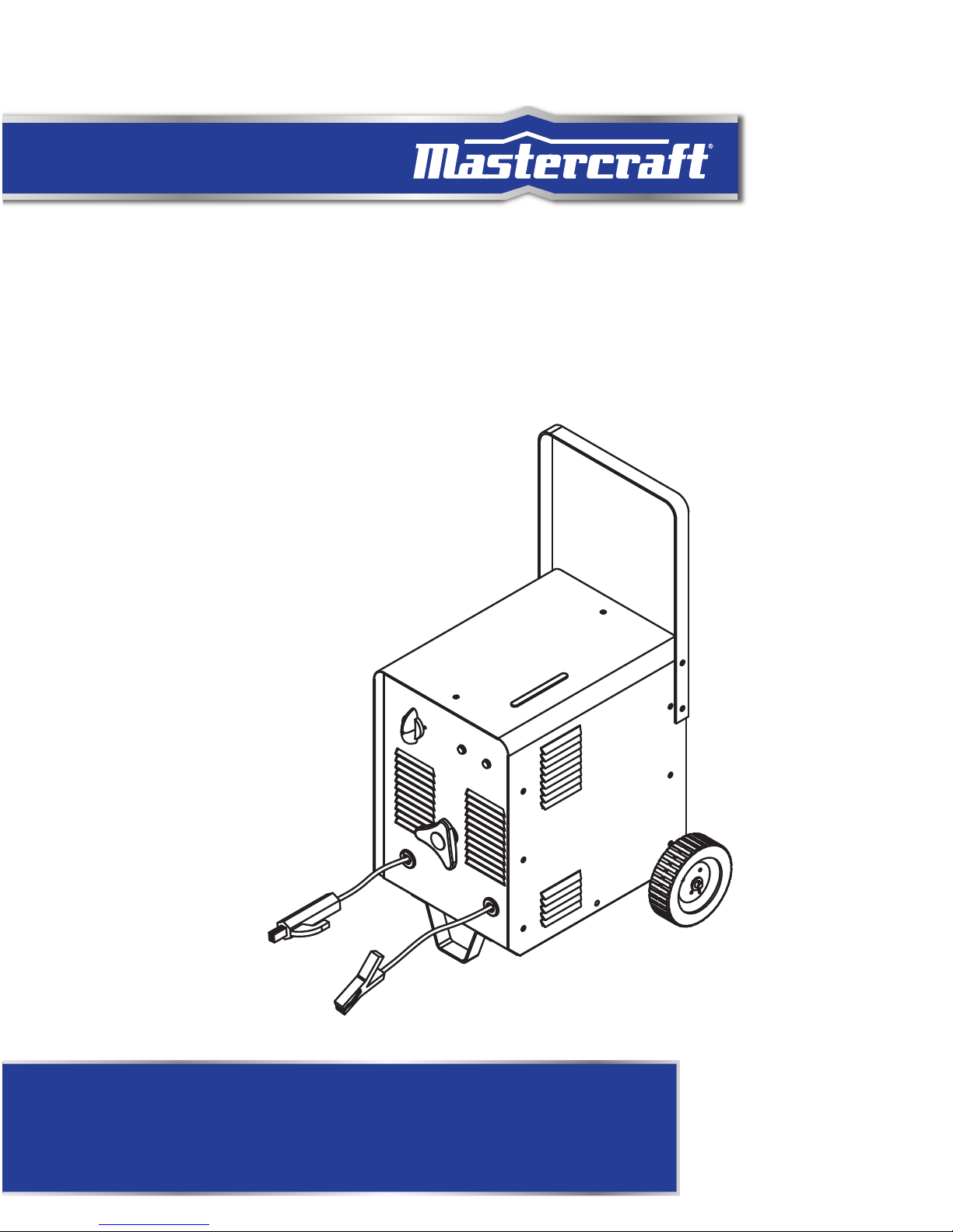
ARC STICK WELDER
IMPORTANT:
Please read this manual carefully before using this arc welder
and save it for reference.
Page 2

model no. 058-1294-8 | contact us 1-800-689-9928model no. 058-1294-8 | contact us 1-800-689-9928model no. 058-1294-8 | contact us 1-800-689-9928
model no. 058-8194-4 | contact us 1-800-689-9928
STNETNOC FO ELBAT
32
3
STNETNOCFOELBAT
TABLE OF CONTENTS
SPECIFICATIONS
4
SAFETY GUIDELINES
5
ASSEMBLY PREPARATION
6
PACKAGE CONTENTS
7
KEY PARTS DIAGRAM
9
OPERATING INSTRUCTIONS
10
MAINTENANCE
17
PARTS LIST
19
WARRANTY
20
EXPLODED VIEW
18
21
NOTE:
If any parts are missing or damaged, or if you have any questions, please call our
toll-free helpline at 1-800-689-9928.
SAVE THESE INSTRUCTIONS
This manual contains important safety and operating instructions. Read all
instructions and follow them when using this product.
TROUBLESHOOTING
model no. 299-5511-4 | contact us 1-800-689-9928
Page 3

4 5
SNOITACIFICEPS
SAFETY GUIDELINES
Please read and save these instructions. Read through this owner’s manual carefully before using product.
Protect yourself and others by observing all safety information, warnings, and cautions.
Model number 058-1294-8
Power 230 V, 60 Hz, 1 Phase
Voltage 50 V (no load)
60–180 A
Output current
Duty cycle 10% at 180 A
Electrodes used 1/16, 5/64, 3/32, 1/8, 5/32" (1.6, 2, 2.4, 3.2, 4 mm)
Metal thickness 18-gauge–1/8” (1.2–3 mm)
Dimensions (L x W x H) 17 5/16 x 14 13/16 x 28 1/8" (44,0 x 37,7 x 71,4 cm)
Weight 55 lb (25 kg)
1. Keep the environment you will be welding in free from flammable materials.
2. Always keep a fire extinguisher accessible to your welding environment.
3. Always have a qualified person install and operate this equipment.
4. Make sure the area is clean, dry and ventilated. Do not operate the welder in humid, wet or poorly
ventilated areas.
5. Always have your welder maintained by a qualified technician in accordance with local, provincial
and national codes.
6. Always be aware of your work environment. Be sure to keep other people, especially children, away
from you while welding.
7. Check all components to ensure they are clean and in good operating condition before use.
8. Do not operate the welder if the output cable, electrode, or any part of the system is wet.
9. Do not immerse them in water.
10. Do not allow any body part to come in contact with the electrode if you are in contact with the
material being welded, ground or electrode from another welder.
11. Do not weld if you are in an awkward position. Always have a secure stance while welding to
prevent accidents. Wear a safety harness if working above ground.
12. Do not drape cables over or around your body.
13. Wear a full-coverage helmet with shade (see ANSI Z87.1 safety standard) and safety glasses while
welding.
14. Wear proper gloves and protective clothing to prevent your skin from being exposed to hot metals,
UV and IR rays.
15. Do not overuse or overheat your welder. Allow proper cooling time between duty cycles.
16. Always use this welder in the rated duty cycle to prevent excessive heat and failure.
17. Do not attempt to repair or maintain the welder while the power is on.
18. Do not touch the electrode and the ground or grounded work piece at the same time.
19. Do not use a welder to thaw frozen pipes.
SPECIFICATIONS SAFETY GUIDELINES
WARNING!
Read all safety warnings and instructions before attempting to install or operate this product. Failure to follow the warnings and
instructions may result in personal injury and property damage.
CAUTION!
The warnings, precautions, and instructions discussed in this instruction manual cannot cover all possible conditions and
situations that may occur. It must be understood by the operator that common sense and caution are factors which cannot be
built into this product, but must be supplied by the operator.
model no. 058-1294-8 | contact us 1-800-689-9928model no. 058-1294-8 | contact us 1-800-689-9928model no. 058-1294-8 | contact us 1-800-689-9928
model no. 058-1294-8 | contact us 1-800-689-9928
Page 4
model no. 058-1294-8 | contact us 1-800-689-9928
PACKAGE CONTENTS
6
7
ASSEMBLY PREPARATION
1 Remove cartons, bags or foam containing the welder and accessories.
2 Check the contents with the packing list below.
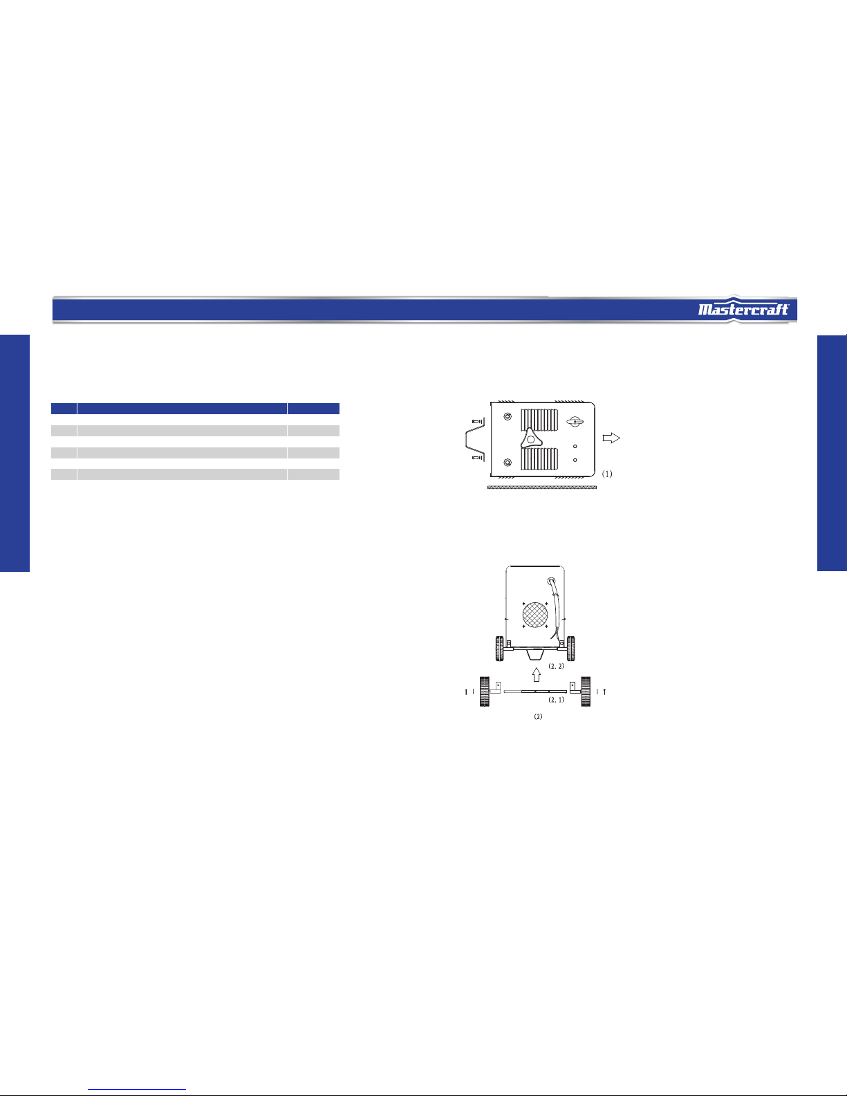
2.2 Install the axle tube/bracket for the axles and wheels on the axle as shown in Fig. 2.1.
Stand the machine up and install the axle tube/bracket onto the back of panel using the screws and
washers provided. (You may want to prop the welder with wooden blocks for this step.)
ITEMNo. QTY.
ARC welder 1 unit
Handle 1 pc
1 pc
Wheel kit (axle, wheels , axle holder etc)
Support 1 pc
Fastener pack 1 pair
Operator s manual
1 pc
1
2
3
4
5
6
PACKAGE CONTENTS
ASSEMBLY
1. Tools required for assembly: 8 and 10 mm open-end wrenches .
2.2.1 Lay the machine side panel on a flat surface. Install the metal bracket support on the bottom
using two sets of screws and washers from the hardware bag. See following image.
model no. 058-1294-8 | contact us 1-800-689-9928
,
model no. 058-1294-8 | contact us 1-800-689-9928model no. 058-1294-8 | contact us 1-800-689-9928model no. 058-1294-8 | contact us 1-800-689-9928
model no. 058-1294-8 | contact us 1-800-689-9928
,
model no. 058-1294-8 | contact us 1-800-689-9928model no. 058-1294-8 | contact us 1-800-689-9928model no. 058-1294-8 | contact us 1-800-689-9928
model no. 058-1294-8 | contact us 1-800-689-9928
model no. 058-1294-8 | contact us 1-800-689-9928model no. 058-1294-8 | contact us 1-800-689-9928model no. 058-1294-8 | contact us 1-800-689-9928
model no. 058-1294-8 | contact us 1-800-689-9928
Page 5

model no. 058-1294-8 | contact us 1-800-689-9928
8
9
NOITARAPERP YLBMESSA
MARGAID STRAP YEK
KEY PARTS DIAGRAM
Description
Weldingcable and electrode holder
No.
A
B
C
D
E Ground cable and clamp
Current adjustment
WARNING!
Make sure the welder is disconnected to the power supply when operating.
When machine is laid on its side, do it gently or the impact could damage internal components.
During installation use caution not to do personal injury from lifting.
ON/OFF switch
Indicator lights
2.3 Finally, install the handle using four sets of screw and washers as shown:
model no. 058-1294-8 | contact us 1-800-689-9928model no. 058-1294-8 | contact us 1-800-689-9928model no. 058-1294-8 | contact us 1-800-689-9928
model no. 058-1294-8 | contact us 1-800-689-9928
A
C
D
B
E
Page 6

model no. 058-1294-8 | contact us 1-800-689-9928
OPERATING INSTRUCTIONS
OPERATING INSTRUCTIONS
11
10
The welding electrode is a rod coated with a layer of flux. When welding, electrical current
flows between the electrode (rod) and the grounded metal workpiece. The intense heat of the arc
between the rod and the grounded metal melts the electrode and the flux. The most popular
electrodes are:
—E6011 60,000 PSI tensile strength for deep penetrating applications.
—E6013 60,000 PSI tensile strength used for poor fit-up applications.
—E7014 70,000 PSI tensile strength used for high deposition and fast travel speeds with
light penetration.
—E7018 70,000 PSI tensile strength (not suitable for this welder).
This welder is capable of welding with 1/16" (1.6 mm) and 5/64" (2 mm) and 3/32" (2.4 mm)
electrodes.
WELDING POSITION
There are two basic positions for welding: flat and horizontal. Flat welding is generally easier, faster, and
allows for better penetration. If possible, the workpiece should be positioned so that the bead will run on a
flat surface.
PREPARING THE JOINT
Before welding, the surface of the workpiece must be free of dirt, rust, scale, oil or paint, which create a
brittle and porous weld. If the base metal pieces to be joined are thick or heavy, it may be necessary to
bevel the edges with a metal grinder. The correct bevel should be around 60 degrees. See following picture:
Based on different welding positions, there are different welding joints; see following images for more
information:
GROUND CLAMP CONNECTION
Clear any dirt, rust, scale, oil or paint on the ground clamp. Make certain you have a good solid ground
connection. A poor connection at the ground clamp will waste power and heat. Make sure the ground clamp
touches the metal.
OPERATING INSTRUCTIONS
ELECTRODE SELECTION
model no. 058-1294-8 | contact us 1-800-689-9928model no. 058-1294-8 | contact us 1-800-689-9928model no. 058-1294-8 | contact us 1-800-689-9928
model no. 058-1294-8 | contact us 1-800-689-9928
Page 7

13
model no. 058-1294-8 | contact us 1-800-689-9928
OPERATING INSTRUCTIONS
SELECTING THE PROPER ELECTRODE
There is no golden rule that determines the exact rod or heat setting required for every situation.
The type and thickness of metal and the position of the workpiece determine the electrode type
and the amount of heat needed in the welding process. Heavier and thicker metals require more
amperage. It is best to practice your welds on scrap metal which matches the metal you intend
to work with to determine correct heat setting and electrode choice. See the following
troubleshooting tips to determine if you are using the correct electrode
When the proper rod is used:
a.1The bead will lay smoothly over the work without ragged edges.
b. The base metal puddle will be as deep as the bead that rises above it.
c. The welding operation will make a crackling sound similar to the sound of eggs frying.
When a rod too small is used:
a. The bead will be high and irregular.
b. The arc will be difficult to maintain.
When the rod is too large:
a. The arc will burn through light metals.
b. The bead will undercut the work.
c. The bead will be flat and porous.
d. The rod may freeze or stick to the workpiece.
12
OPERATING INSTRUCTIONS
1. Setting the amperage control
The welder has an infinite output current control. It is capable of welding with 1/16, 5/64, 3/32, 1/8,
and 5/32" electrodes.
There is no golden rule that determines the exact amperage required for every situation. It is best to test
your welds on scrap metal which matches the metals you intend to work with to determine
correct setting for your job. The electrode type and the thickness of the workpiece metal determine the
amount of heat needed in the welding process. Heavier and thicker metals require more voltage
(amperage), whereas lighter and thinner metals require less voltage (amperage).
2. Welding techniques
The best way to teach yourself how to weld is with short periods of practice at regular intervals. All
practice welds should be done on scrap metal that can be discarded. Do not attempt to make any repairs
on valuable equipment until you have satisfied yourself that your practice welds are of good appearance
and free of slag or gas inclusions.
2.1 Holding the electrode
The best way to grip the electrode holder is the way that feels most comfortable to you. To position the
electrode to the workpiece when striking the initial arc it may be necessary to hold the electrode perpendicular to the workpiece. Once the arc is started the angle of the electrode in relation to the workpiece
should be between 10 and 30 degrees. This will allow for good penetration, with minimal spatter.
2.2 Striking the arc
Scratch the work piece with the end of the electrode to start an arc and then raise it quickly to about a
1/8" gap between the rod and the workpiece. See the following picture:
WARNING!
Rate of travel over the work also affects the weld. To ensure proper penetration and
enough deposit of rod, the arc must be moved slowly and evenly along the weld seam.
2
3
model no. 058-1294-8 | contact us 1-800-689-9928model no. 058-1294-8 | contact us 1-800-689-9928model no. 058-1294-8 | contact us 1-800-689-9928
model no. 058-1294-8 | contact us 1-800-689-9928
Page 8

14 15
model no. 058-1294-8 | contact us 1-800-689-9928
SNOITCURTSNI GNITAREPO
SNOITCURTSNI GNITAREPO
It is important that the gap be maintained during the welding process and it should be neither too
wide nor too narrow. If too narrow, the rod will stick to the workpiece. If too wide, the arc will
be extinguished. It needs much practice to maintain the gap. Beginners may usually get sticking
or arc extinguishing. When the rod sticks to the workpiece, gently rock it back and forth to make
it release. If not, the circuit will be shorted, and it will overload the welder. A good arc is
accompanied by a crisp, crackling sound. The sound is similar to that made by eggs frying. To
lay a weld bead, only 2 movements are required; downward and in the direction the weld is to be
laid, as in the following figure:
2.3 Types of weld bead
The following paragraphs discuss the most commonly used arc welding beads. The stringer bead
is formed by travelling with the electrode in a straight line while keeping it
centred over the weld joint.
The weave bead is used when you want to deposit metal over a wider space than would be
possible with a stringer bead. It is made by weaving from side to side while moving with the
electrode. It is best to hesitate momentarily at each side before weaving back the other way to
improve penetration.
2.4 Welding position
The flat position is the easiest of the welding positions and is most commonly used. It is best if you can
weld in the flat position if at all possible as good results are easier to achieve.
The horizontal position is performed very much the same as the flat weld except that the angle is different
such that the electrode, and therefore the arc force, is directed more toward the metal above the weld joint.
This more direct angle helps prevent the weld puddle from running downward while still allowing slow
enough travel speed to achieve good penetration. A good starting point for your electrode angle is about 30
degrees DOWN from being perpendicular to the workpiece.
2.5 Judge a good weld bead
When the trick of establishing and holding an arc has been learned, the next step is learning how to run a
good bead. The first attempts in practice will probably fall short of acceptable weld beads. Too long an arc
will be held or the travel speed will vary from slow to fast. See the following picture:
A. Weld speed is too fast.
B. Weld speed is too slow.
C. Arc is too long.
D. Ideal weld.
model no. 058-1294-8 | contact us 1-800-689-9928model no. 058-1294-8 | contact us 1-800-689-9928model no. 058-1294-8 | contact us 1-800-689-9928
model no. 058-1294-8 | contact us 1-800-689-9928
Page 9

17
model no. 058-1294-8 | contact us 1-800-689-9928
MAINTENANCE
16
OPERATING INSTRUCTIONS
A solid weld bead requires that the electrode be moved slowly and steadily along the weld seam.
Moving the electrode rapidly or erratically will prevent proper fusion or create a lumpy, uneven
bead. To prevent ELECTRIC SHOCK, do not perform any welding while standing, kneeling, or lying
directly on the grounded work.
2.6 Finish the bead
As the coating on the outside of the electrode burns off, it forms an envelope of protective gasses
around
the weld. This prevents air from reaching the molten metal and
creates an undesirable
chemical reaction. The burning coating, however, forms slag. The slag formation appears as an
accumulation of dirty metal scale on the finished weld. Slag should be removed by striking the
joined by welding. Peening the weld not
only removes the scale left behind in the welding but
relieves
the internal strains developed by the heating and cooling process. Use a hammer or brush
after the workpiece has cooled.
MAINTENANCE
The welder needs regular maintenance:
• Periodically clean dust, dirt, grease, etc. from your welder. Every six months, or as necessary,
remove the cover panel from the welder and air-blow any dust and dirt that may have accumulated
inside the welder.
• Replace power cord, ground cable, ground clamp, or electrode assembly when damaged or worn.
• Store in a clean dry facility, free from corrosive gas, excess dust and high humidity. Store in a
temperature range from -12 to 49ºC (10 to 120ºF) and relative humidity not more than 90%.
• When transporting or storing the welder after use, it is recommended to repack the product as it
was received for protection. Cleaning is required before storage and you must seal the plastic bag
in the box for storage.
model no. 058-1294-8 | contact us 1-800-689-9928model no. 058-1294-8 | contact us 1-800-689-9928model no. 058-1294-8 | contact us 1-800-689-9928
model no. 058-1294-8 | contact us 1-800-689-9928
• Always wear qualified safety goggles and full face shield when using the welder.
WARNING!
weld with a chipping hammer. The intense heat produced at the arc sets up strains in the metals
Page 10

18
19
TROUBLESHOOTING
PARTS LIST
model no. 058-1294-8 | contact us 1-800-689-9928
TROUBLESHOOTING
Problem
Possible Cause
Corrective Action
1. Check circuit breaker or
fuse in power source.
2. Replace power cord.
3. Replace switch.
4. Replace the transformer.
1. Check the power source.
2. Check for proper grounding
to the work piece.
3. Check output connection.
4. Clean surfaces.
5. Use correct wire.
1. Use recommended electrode.
2. Make sure there is a good
ground connection.
Check the fuse in power
source. It should be a 50 A fuse.
Slow down the welding
speed.
1. Use dry one.
2. Use corrent one.
1. Damp electrode.
2. Wrong type electrode.
The welding speed too slow.
The welding speed is too fast.
Wrong fuse in power supply.
1. Incorrect power input.
2. Inadequate current at output.
3. Poor connection of output cable.
4. Dirty surfaces.
5. Wrong welding wire.
1. The wrong electrode.
2. Base metal not grounded
properly.
Electrode is in contact with the
work piece too long
when starting arc.
Contact us.
Speed up the welding speed.
After the arc has started, move
the electrode away from the
work piece immediately.
1. No power input.
2. The power cord or power plug
is broken.
3. Main switch is broken.
4. Transformer is broken.
Welder does not work
when the main switch
is turned on.
Does not weld.
Blows fuse.
Arc is hard to start.
Welding bead too thin.
Welding bead too thick.
Electrode sticks to work
piece.
Poor welding
performance; spatter.
Others.
EXPLODED VIEW
1
2
3
4
4.2
4.1
5 6
4.4
4.3
7
8
9
10
11
12
13
14
15
16
19
20
21
22
23
24
25
18
17
model no. 058-1294-8 | contact us 1-800-689-9928model no. 058-1294-8 | contact us 1-800-689-9928model no. 058-1294-8 | contact us 1-800-689-9928
model no. 058-1294-8 | contact us 1-800-689-9928
Page 11

20
21
PARTS LIST
WARRANTY
PARTS LIST
3-Year Limited Warranty
This Mastercraft product is guaranteed for a period of three (3) years from the date of original retail
purchase, against defects in materials and workmanship.
Subject to the conditions and limitations described below, this product, if returned to us with proof of
purchase within the stated warranty period and if covered under this warranty, will be repaired or replaced
(with the same model, or one of equal value or specification), at our option. We will bear the cost of any
repair or replacement and any costs of labour relating thereto.
These warranties are subject to the following conditions and limitations :
a) a bill of sale verifying the purchase and purchase date must be provided;
b) this warranty will not apply to any product or part thereof which is worn or broken or which has become inoperative
due to abuse, misuse, accidental damage, neglect or lack of proper installation, operation or maintenance
(as outlined in the applicable owner’s manual or operating instructions) or which is being used for industrial,
professional, commercial or rental purposes;
c) this warranty will not apply to normal wear and tear or to expendable parts or accessories that may be supplied with
the product which are expected to become inoperative or unusable after a reasonable period of use;
d) this warranty will not apply to routine maintenance and consumable items such as, but not limited to, fuel, lubricants,
vacuum bags, blades, belts, sandpaper, bits, fluids, tune-ups or adjustments;
e) this warranty will not apply where damage is caused by repairs made or attempted by others (i.e. persons not
authorized by the manufacturer);
f) this warranty will not apply to any product that was sold to the original purchaser as a reconditioned or refurbished
product (unless otherwise specified in writing);
g) this warranty will not apply to any product or part thereof if any part from another manufacturer is installed therein or
any repairs or alterations have been made or attempted by unauthorized persons;
h) this warranty will not apply to normal deterioration of the exterior finish, such as, but not limited to, scratches, dents,
paint chips, or to any corrosion or discolouring by heat, abrasive and chemical cleaners;
i) this warranty will not apply to component parts sold by and identified as the product of another company, which shall
be covered under the product manufacturer’s warranty, if any.
If any part is missing or damaged, do not use the product until the missing or damaged part has been replaced.
WARNING!
NOTE:
The manufacturer and/or distributor has provided the parts list and assembly diagram in this manual as a reference tool only. Neither the
manufacturer nor distributor makes any representation or warranty of any kind to the buyer that he or she is qualified to make any repairs to the
product, or that he or she is qualified to replace any parts of the product. In fact, the manufacturer and/or distributor expressly states that all repairs
and parts replacements should be undertaken by certified and licensed technicians, and not by the buyer. The buyer assumes all risk and liability
arising out of his or her repairs to the original product or replacement parts thereto, or arising out of his or her installation of replacement parts
thereto.
model no. 058-1294-8 | contact us 1-800-689-9928model no. 058-1294-8 | contact us 1-800-689-9928model no. 058-1294-8 | contact us 1-800-689-9928
model no. 058-1294-8 | contact us 1-800-689-9928
No. Description
No. Description
Clamp11
Handle1
Index panel2
Panel3
Iron core 1
4
Clip clutch
4.1
Thermal relay4.2
Iron core 24.3
Bracket4.4
Screw plug spring5
Pointer6
Wheel8
Indictor light9
Switch10
Rubber circle7
1
1
1
1
2
1
2
1
1
1
1
1
1
1
2
1
1
1
1
1
2
2
2
1
1
1
1
1
1
Grounding cable12
Welding cable13
Fixed bracket14
Frame
15
Fan16
Cotter17
Washer18
Wheel 19
Axle bracket20
Axle21
Cable clamp23
Power cable24
Coil25
22 Axle bracket
Qty
Qty
Page 12

headline bars
model no. 058-1294-8 | contact us 1-800-689-9928
22
Additional Limitations
This warranty applies only to the original purchaser and may not be transferred. Neither the retailer nor
the manufacturer shall be liable for any other expense, loss or damage, including, without limitation, any
indirect, incidental, consequential or exemplary damages arising in connection with the sale, use or inability
to use this product.
This warranty gives you specific legal rights, and you may have other rights, which may vary from province
to province. The provisions contained in this warranty are not intended to limit, modify, take away from,
disclaim or exclude any statutory warranties set forth in any applicable provincial or federal legislation.
Made in China
Imported by
Mastercraft Canada Toronto, Canada M4S 2B8
WARRANTY
Notice to Consumer
 Loading...