

Page 1
INSTRUCTION
MANUAL
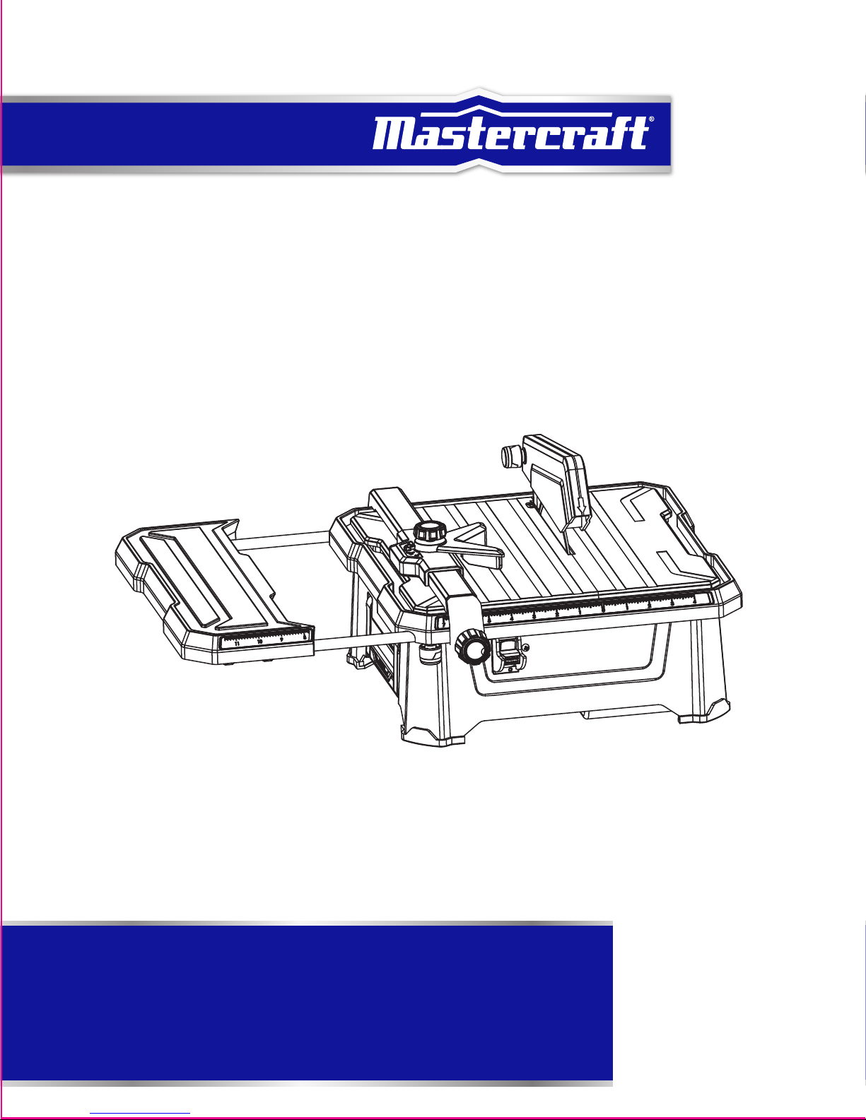
TABLETOP
WET TILE SAW WITH
EXTENSION TABLE
IMPORTANT:
Please read this manual carefully before using this tile
saw with extension table and save it for reference.
model no. 055-6778-4
Page 2

3
TABLE OF CONTENTS
SAVE THESE INSTRUCTIONS
This manual contains important safety and operating instructions. Read all
instructions and follow them when using this product.
NOTE:
If any parts are missing or damaged, or if you have any questions, please call our
toll-free helpline at: 1-800-689-9928
TABLE OF CONTENTS
Quick Start Guide
Specifications
Safety Guidelines
Know Your Tile Saw
Assembly Instructions
Operating Instructions
Maintenance
Troubleshooting
Exploded View
Parts List
Warranty
4
5
6-12
13-14
15-22
23-27
28-29
30
31
32-33
34
Page 3
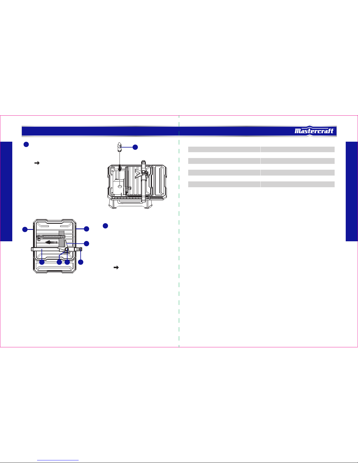
• Gently turn locking knob (2) on parallel
cutting guide counter-clockwise to loosen.
• Adjust the parallel cutting guide in the
desired position using the parallel cutting
guide scale (3), located on front and rear
of table, to set parallel cutting guide to
desired width of cut.
• Turn locking knob clockwise to tighten
securely.
see page 24
• Locate hole on bottom of water fill
reservoir.
• Push water reservoir plug (1) into hole
firmly.
see page 21
1
model no. 055-6778-4 | contact us 1-800-689-9928
SPECIFICATIONS
Motor
Speed
Table tilts
Blade
Table size
Max. cutting thickness
Weight
120V, 60 Hz, 5.0A
5300 RPM (no load)
0°,15°, 30° & 45°
7" (17.8 cm) diamond-tipped
13 9/16 x 13 9/16" (34.5 x 34.5 cm)
1 3/16" (30 mm) at 90°; 15/32" (12 mm) at 45°
16 lb 8 oz (7.5 kg)
5
SPECIFICATIONS
4
QUICK START GUIDE
2
1
3
3
4
1 65 2
Page 4
WARNING!
To avoid mistakes that could cause serious injury, do not plug in the tile saw
until you have read and understood the rules.
DANGER!
Potential hazard that will result in serious injury or loss of life.
WARNING!
Potential hazard that could result in serious injury or loss of life.
CAUTION!
Potential hazard that may result in moderate injury or damage to equipment.
7
SAFETY GUIDELINES
6
SAFETY GUIDELINES
SAFETY GUIDELINES
This manual contains information that relates to PROTECTING PERSONAL SAFETY and PREVENTING
EQUIPMENT PROBLEMS. It is very important to read this manual carefully and understand it thoroughly before
using the product. The symbols listed below are used to indicate this information.
Note: The word “Note” is used to inform the reader of something the operator needs to know about the tool.
SAFETY RECOMMENDATIONS
These precautions are intended for the personal safety of the operator and others working with the operator.
Failure to follow these instructions may result in a permanent loss of vision, serious personal or even fatal
injury, property damage and/or tool damage. Please take time to read and understand them.
Safety is a combination of common sense, staying alert- and knowing how your wet tile saw works.
BEFORE USE
• For safe handling of this product, the user must have read and understood the instructions for use before
using it for the first time.
• Observe all safety instructions! If you do not observe the safety instructions you will endanger yourself
and others.
• Keep all use and safety instructions for future reference.
• Attach the instructions for use, if you pass on the product to someone else.
• KEEP WORK AREA CLEAN. Cluttered areas and benches invite accidents.
• All parts of the product, safety devices in particular, must be correctly installed to ensure faultless
operation.
OPERATION/WORKPLACE
• KEEP GUARDS IN PLACE and in working order.
• REMOVE ADJUSTING KEYS AND WRENCHES. Form habit of checking to see that keys and adjusting
wrenches are removed from tool before turning it on.
• KEEP CHILDREN AWAY. All visitors should be kept at a safe distance from work area.
• MAKE WORKSHOP CHILDPROOF with padlocks, master switches or by removing starter keys.
• DON'T FORCE TOOL. It will do the job better and safer at the rate for which it was designed.
• USE THE RIGHT TOOL. Don't force tool or attachment to do a job for which it was not designed.
• DON'T OVERREACH. Keep proper footing and balance at all times.
• REDUCE THE RISK OF UNINTENTIONAL STARTING. Make sure switch is in the Off position before plugging
in.
• DIRECTION OF FEED. Feed work into a cutting disc against the direction of rotation of the blade or cutter
only.
• NEVER LEAVE TOOL RUNNING UNATTENDED. TURN POWER OFF. Don't leave tool until it comes to a
complete stop.
• The product may be used only when in a good working condition. If the product or part of the product is
defective, have it repaired by an expert.
• Always follow the applicable national and international safety, health and labour regulations.
• The product may only be used if no defects are found during the inspection. Ensure that any
defective parts are replaced before the product is used again.
• Position the product horizontally on a rigid, even surface with adequate load-bearing capacity.
• Do not leave any tools, objects or cables lying in the working range of the device.
• Ensure that there is sufficient lighting during operation.
• Assume a natural and secure stance when working.
• Make sure that during operation, no body parts or clothing are caught and drawn in by rotating
components.
• The immediate environment must be free of combustible and other flammable or explosive substances.
• Young people under 18 years of age and users who are not sufficiently familiar with its operation must not
use the product.
• Persons unable to safely and carefully use the tool for physical, psychological and neural reasons must
not use the product.
• Work with caution and only if you are physically fit: Working under the effects of fatigue, illness, alcohol,
medication and drugs is irresponsible, as you are unable to use the product safely.
SERVICE
• DISCONNECT TOOLS before servicing or when changing accessories, such as cutting discs.
• Have your electrical tool repaired only by qualified technicians, using only genuine spare parts. This will
maintain the safety of the electrical tool.
• DON'T USE IN A DANGEROUS ENVIRONMENT. Don't use power tools in damp or wet locations, or expose
them to rain. Keep work area well lit.
• MAINTAIN TOOLS WITH CARE. Keep tools sharp and clean for best and safest performance. Follow
instructions for lubricating and changing accessories.
• CHECK FOR DAMAGED PARTS. Before further use of the tool, a guard or other part that is damaged should
model no. 055-6778-4 | contact us 1-800-689-9928
Page 5
WARNING!
For your own safety, read instruction manual before operating saw.
• Wear eye protection.
• Use splash guard for every operation for which it can be used.
• Disconnect saw before servicing, when changing cutting wheels and cleaning.
• Use tool only with smooth edge cutting wheels free of openings and grooves.
• Replace damaged cutting wheel before operating.
• Do not fill water tank above water fill line.
9
SAFETY GUIDELINES
8
SAFETY GUIDELINES
be carefully checked to determine that it will operate properly and perform its intended function. Check
for alignment of moving parts, binding of moving parts, breakage of parts, mounting and any other
conditions that may affect operation. A guard or other part that is damaged should be properly repaired
or replaced.
• Only the maintenance work and troubleshooting activities described in these instructions may be carried
out. All other work must be carried out by an expert.
• Conversions, unauthorized modifications and the use of non-approved parts are prohibited.
PRODUCT-SPECIFIC SAFETY WARNINGS
• Make sure that you always stand to the side of the cutting disc.
• WEAR PROPER APPAREL. Do not wear loose clothing, gloves, neckties, rings, bracelets or other jewelry
that may get caught in moving parts. Non-slip footwear is recommended. Wear protective hair covering
to contain long hair.
• ALWAYS USE SAFETY GLASSES. Also use face or dust mask if cutting operation is dusty. Everyday
eyeglasses only have impact-resistant lenses; they are NOT safety glasses.
• USE RECOMMENDED ACCESSORIES. Consult the owner's manual for recommended accessories. The use
of improper accessories may cause risk of injury.
• NEVER STAND ON TOOL. Serious injury could occur if the tool is tipped or if the cutting tool is
unintentionally contacted.
• Use only cutting discs that are suitable for the product.
• Only use cutting discs in good working condition. Remove damaged or worn cutting discs immediately.
• Never use segmented cutting discs.
• Faults in the machine, including guards or diamond discs, should be reported as soon as they are
discovered. Never use the machine without the guard in position.
• Do not twist or bend workpieces.
• Never cut several workpieces simultaneously. Do not cut bundles made of several individual pieces. A
workpiece can get caught in the cutting disc and fly out of control.
• Never cut workpieces on which there are ropes, cords, bands, cables or wires containing such materials.
• Make regular checks to ensure that the cutting disc is correctly fastened.
• Make sure that during the cutting operation, an adequate quantity of cooling water reaches the cutting
surfaces of the disc at all times.
• Never cut wood or metal with this saw.
• Always maintain sufficient distance from the cutting disc. Switch off the product and wait until the cutting
disc stops before removing workpieces, residual material etc. from the work area.
• Always pull out the mains plug (disconnect the product from its power supply) before commencing work
on the product.
• A cutting disc can cause injuries, even when stationary! Use protective gloves to change the cutting disc.
• Never use lateral counter pressure to bring the cutting disc to a standstill after switching off the drive.
• Replace table insert when worn.
• Use only diamond discs recommended by the manufacturer.
• Never use blades on this machine.
• Use only diamond discs for which the maximum possible speed is not less than the maximum spindle
speed of the tool and the material to be cut.
• Maximum size of working piece should be 10 sq. ft. (1 m
2
).
• This tile saw should be used at an ambient temperature only between 59-80°F (15-50°C).
• USE PROPER EXTENSION CORD. Make sure your extension cord is in good condition. When using an
extension cord, be sure to use one heavy enough to carry the current your product will draw. An
undersized cord will cause a drop in line voltage, resulting in loss of power and overheating. Page 12
shows the correct size to use depending on cord length and nameplate ampere rating. If in doubt, use the
next heavier gauge. The smaller the gauge number, the heavier the cord.
STORAGE AND TRANSPORT
• Always store the product in a dry place.
• Store the product in a frost-free place.
• Protect the product from damage during transport.
• Keep the product away from children. Store the product in a place where it is safe from children and
unauthorized persons.
RESIDUAL RISKS
• Even when the product is used properly and in compliance with all the safety precautions in these
instructions for use, the following residual risks can arise:
• Touching the cutting disc in the exposed area.
• Reaching into the spinning cutting disc.
• Rebound from workpieces and workpiece parts.
• Cutting disc breaks.
• Faulty cutting disc diamond attachment being flung out.
• Hearing damage through failure to wear the requisite hearing protection.
model no. 055-6778-4 | contact us 1-800-689-9928
Page 6
WARNING!
• Use the proper extension cord. Make sure to use an extension cord that is heavy enough to carry
the current required by the tool. An undersized cord will cause a drop in line voltage, resulting in
loss of power and overheating of the tool.
• Use the extension cord only for intended purpose. Do not pull the extension cord to remove it
from the power socket.
CAUTION!
In all cases, verify that the outlet in question is properly grounded. If you are not sure, have a
licensed electrician check the outlet.
11
SAFETY GUIDELINES
10
SAFETY GUIDELINES
USE SAFETY GOGGLES AND EAR PROTECTION:
ALWAYS WEAR EYE PROTECTION THAT CONFORMS WITH CUL REQUIREMENTS. FLYING
DEBRIS can cause permanent eye damage.
The tool is loud and the sound can cause hearing damage. Always wear ear protection to help
prevent hearing damage and loss. Failure to comply may result in moderate injury.
USE DUST MASK:
Some dust created by sawing contains chemicals that are known to cause cancer, birth defects
or other reproductive harm. Some examples of these chemicals come from lead-based paints,
crystalline silica from bricks, cement and other masonry products, arsenic and chromium from
chemically treated lumber. To reduce exposure to these chemicals, work in a well-ventilated
area with approved safety equipment, such as dust masks that are specially designed to filter out microscopic
particles.
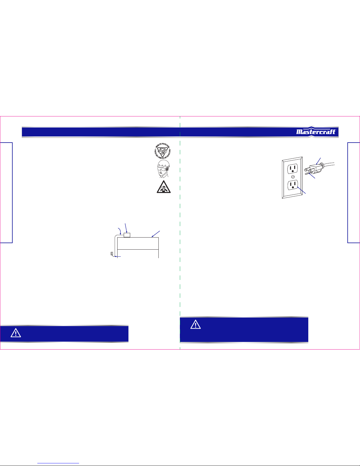
POSITION OF TILE SAW
• To avoid the possibility of the appliance plug or
receptacle getting wet, position tile saw to one side of
a wall-mounted receptacle to prevent water from
dripping onto the receptacle or plug. The user should
arrange a "drip loop" in the cord connecting the saw
to a receptacle. The "drip loop" is the part of the cord
below the level of the receptacle, or the connector if
an extension cord is used, to prevent water traveling
along the cord and coming into contact with the
receptacle.
• If the plug or receptacle does get wet, DON’T unplug
the cord. Disconnect the fuse or circuit breaker that
supplies power to the tool. Then unplug and examine for presence of water in the receptacle.
ELECTRICAL SAFETY
GUIDELINES FOR USING EXTENSION CORDS:
In the event of a malfunction or breakdown, grounding provides a path of least resistance for electric current
to reduce the risk of electric shock. This tool is equipped with an electric cord having an equipment-grounding
conductor and a grounding plug. The plug must be plugged into a matching outlet that is properly installed
and grounded in accordance with all local codes and ordinances.
Do not modify the plug provided. If it will not fit the outlet, have the proper outlet installed by a qualified
electrician.
Improper connection of the equipment-grounding conductor
can result in a risk of electric shock. The conductor with
a green outer surface, with or without yellow stripes, is the
equipment-grounding conductor. If repair or replacement
of the electric cord or plug is necessary, do not connect the
equipment-grounding conductor to a live terminal.
Check with a qualified electrician or service technician if
the grounding instructions are not completely understood,
or if in doubt as to whether the tool is properly grounded.
Use only three-wire extension cords that have three-prong
grounding plugs and three-pole receptacles that accept
the tool’s plug, as shown in Fig. 2. Repair or replace a damaged or worn cord immediately.
GROUNDING INSTRUCTIONS:
• Make sure the extension cord is in good condition. When using an extension cord, be sure to use one
that is heavy enough to carry the current that your product will draw. An undersized cord will cause a
drop in line voltage, which will result in loss of power and overheating. The table on the next page shows
the correct size to be used according to cord length and nameplate ampere rating. When in doubt, use
the next heavier gauge. The smaller the gauge number, the heavier the cord.
• Make sure your extension cord is properly wired and in good condition. Always replace a damaged
extension cord, or have it repaired by a qualified person before using it. Protect your extension cords from
sharp objects, excessive heat, and damp or wet areas.
• Use a separate electrical circuit for your tools. This circuit must consist of not less than #12 wire with a
20 A time-delayed fuse or a #14 wire with a 15 A time-delayed fuse. Before connecting the motor to the
power line, make sure the switch is in the Off position and the electric current is rated the same as the
current stamped on the motor nameplate. Running at a lower voltage will damage the motor.
Tool
Drip loop
Fig. 1
Supporting surface
Power supply
cord
Fig. 2
Three-prong plug
Grounding prong
Properly grounded outlet
model no. 055-6778-4 | contact us 1-800-689-9928
Page 7

NOTE:
Recycle unwanted materials rather than disposing of them as waste. Sort the tool and its components in
specific categories and take to the local recycling centre or dispose of them in an environmentally safe way.
AMPERAGE RATING OF THE TOOL
(120 V CIRCUIT ONLY)
MORE THAN
0
6
10
12
NOT MORE THAN
6
10
12
16
25' (7.6 m)
18
18
16
14
50' (15.2 m)
16
16
16
12
100' (30.5 m)
16
14
14
Not recommended
150' (45.7 m)
14
12
12
TOTAL LENGTH OF THE EXTENSION CORD
MINIMUM GAUGE FOR THE EXTENSION CORD (AWG)
1312
SAFETY GUIDELINES
Recommended size for extension cords
KNOW YOUR TILE SAW
No.
1
2
3
4
5
6
7
8
9
10
Description
Upper protective guard
Locking knob (for upper protective guard)
Mitre cutting guide
Extension table
Carry handle
Locking knob (for extension table)
On/Off switch
Safety key
Rubber foot
Parallel cutting guide scale
No.
11
12
13
14
15
16
17
18
19
Description
Working table
45° vertical fence
Metal bracket
Cutting disc
Locking knob (for mitre cutting guide)
Parallel cutting guide
Locking knob (for parallel cutting guide)
Water reservoir plug
Lower protective guard
WARNING!
This tool must be grounded while in use in order to protect the operator from electric shock.
model no. 055-6778-4 | contact us 1-800-689-9928
123
1514 16 17
7 8 965
12
11
10
19
4
13
18
Page 8

WARNING!
Do not use cutting discs rated less than the speed of this tool. Failure to heed this warning could
result in personal injury.
15
ASSEMBLY INSTRUCTIONS
14
On/Off switch:
This saw has an easy-access power switch located below the front rail. To lock the switch in the Off position,
remove the switch key from the switch. Place the key in a location that is inaccessible to children and others
not qualified to use the tool.
7" (17.8 cm) Cutting disc:
A 7" (17.8 cm) tile cutting disc is included with your tile saw.
45° vertical fence:
Beveled 15°, 30° and 45° cuts can be made using the 45° vertical fence.
Mitre cutting guide:
The mitre cutting guide is fully adjustable for diagonal cuts and mitre cuts.
Parallel cutting guide:
Parallel cutting guide is fully adjustable for making cross cuts and using the mitre cutting guide.
Upper protective guard:
The upper protective guard prevents accidental contact with the cutting disc and stops workpiece parts and
cooling water from being flung out. The upper protective guard must always be mounted during the operation
and can be lowered to the workpiece.
Lower protective guard:
The lower protective guard prevents accidental contact with the cutting disc and stops workpiece parts and
cooling water from being flung out.
Metal bracket:
The metal bracket prevents a workpiece from being caught by the cutting disc and being hurled at the
operator. The metal bracket must always be mounted during operation.
Parallel cutting guide scale:
The parallel cutting guide scale shows distance from the parallel cutting guide to the saw blade.
Locking knob (for parallel cutting guide):
The locking knob is located on the front of the parallel cutting guide to release or lock the parallel cutting
guide with respect to the working table.
PACKAGE CONTENTS
NO. Description Qty. Illustration
Tile saw assembly
Parallel cutting guide, spring, clamp, flat washer
and locking knob
Mitre cutting guide
Upper protective guard assembly
Metal bracket
Cutting disc
Extension table and locking knob
Water reservoir plug
1
2
3
4
5
6
7
8
1
1
1
1
1
1
1
1
KNOW YOUR TILE SAW
model no. 055-6778-4 | contact us 1-800-689-9928
Page 9

TOOLS NEEDED FOR ASSEMBLY
Star-head screwdriver
WARNING!
If any parts are damaged or missing do not operate this tool until the parts are replaced. Use of
this product with damaged or missing parts could result in serious personal injury.
• Do not attempt to modify this tool or create accessories not recommended for use with this tool.
Any such alteration or modification is misuse and could result in a hazardous condition leading
to possible serious personal injury.
• Do not connect to power supply until assembly is complete. Failure to comply could result in
accidental starting and possible serious personal injury.
• Risk of injury! Always pull out the mains plug (disconnect the product from its power supply)
before commencing work on the product.
17
ASSEMBLY INSTRUCTIONS
16
ASSEMBLY INSTRUCTIONS
UNPACKING
Do not use this product if any parts of the package contents are already assembled to your product when you
unpack it. Package contents are not assembled to the product by the manufacturer and require customer
installation. Use of a product that may have been improperly assembled could result in serious personal injury.
• Inspect the tool carefully to make sure no breakage or damage occurred during shipping.
• Do not discard the packing material until you have carefully inspected and satisfactorily operated the tool.
• The saw is factory set for accurate cutting. After assembling it, check for accuracy. If shipping has
influenced the settings, refer to specific procedures explained in this manual.
• If any parts are damaged or missing, please call: 1-800-689-9928 for assistance.
Fig. 1
Fig. 2
Fig. 3
WARNING!
Be sure to observe the rotational direction of the cutting disc when fitting! Be sure to observe the
free-wheeling of the cutting disc when fitting!
FITTING THE CUTTING DISC (Fig. 1-4)
• Unplug the tile cutter from the mains supply.
• Raise the 45° Vertical fence (1) approx. 45° and
remove.
• Loosen cross-screws (2) with the Star-head screwdriver
(not supplied) and pull off lower protective guard (3).
• Attach the straight wrench (4) (supplied) to the hex
nut (5).
• Lock motor shaft (6) to prevent turning using angled
wrench (7) (supplied).
• Turn the hex nut (5) anti-clockwise.
• Remove the hex nut (5) and outer flange (8).
• Place cutting disc (9) on inner flange (10).
• Attach the outer flange (8), the double “D” flats on the
outer flange align with flats on motor shaft.
• Screw hex nut (5) onto motor shaft (6) clockwise.
• Attach the straight wrench (4) to the hex nut (5).
• Lock motor shaft (6) to prevent turning using angle
wrench (7).
• Tighten hex nut (5) clockwise using straight wrench (4).
• Re-attach the lower protective guard (3) and tighten
cross-screws (2).
CAUTION!
When fitting make sure that the cutting disc is placed correctly on the inner flange. The inner
flange can be moved freely on the motor shaft and has a section for holding the internal hole
of the cutting disc. The hole of the outer flange is not round and is used for the interlocking
connection with the motor shaft.
model no. 055-6778-4 | contact us 1-800-689-9928
NO. Description Qty. Illustration
Wrenches9 2
2
3
8
1
2
5
4
5
7
6
6
Fig. 4
9 8
5
6
10
Page 10

WARNING!
The metal bracket must always be aligned to the cutting disc so that it does not Interfere with
material being cut.
WARNING!
Product damage! Do not over-tighten hex bolt (3) and locking knob (1). The upper protective
guard (4) must be free to rise and fall as the workpiece is pushed toward the cutting disc.
19
ASSEMBLY INSTRUCTIONS
18
ASSEMBLY INSTRUCTIONS
Fig. 5
Fig. 6
Fig. 7
ASSEMBLE/ADJUST THE METAL BRACKET (Fig. 5)
• Loosen two cross-screws (1) with the Star-head
screwdriver (not supplied).
• Push slotted hole in the metal bracket (2) below the
cross-screw (1).
• Gently tighten the cross-screws (1).
• Align metal bracket (2) with the cutting disc (3).
• Tighten cross-screws (1).
• Replace the 45° vertical fence.
MOUNTING THE UPPER PROTECTIVE GUARD (Fig. 6-7)
• Loosen the locking knob (1) and remove the locking knob,
flat washer (2) and hex bolt (3) from the upper protective
guard (4).
• Align upper protective guard (4) with cutting disc and
slide over metal bracket (5). Line up through holes in
upper protective guard with slot in metal bracket.
• Install hex bolt (3) through upper protective guard and
metal bracket. Put the flat washer (2) onto bolt before the
thread locking knob (1) and tighten the locking knob.
• Cover the cutting disc with the upper protective guard (4).
• Ensure that upper protective guard (4) can move freely
and that it cannot touch the cutting disc.
MOUNTING THE EXTENSION TABLE (Fig. 8-10)
• Undo the cross-screws (1) on the guide rails of the
extension table (2).
• Push the guide rails for the extension table (2) on both
sides into the locator of the machine body.
• Refit the cross-screws (1).
• Mounting the locking knob (3).
SETTING EXTENSION TABLE (Fig. 10)
• Loosen the locking knob counter-clockwise.
• Set the extension table to the desired distance from the
cutting disc.
• Tighten the locking knob clockwise.
3
1
2
model no. 055-6778-4 | contact us 1-800-689-9928
32
1
21 3
4
5
1
2 3
Fig. 8
Fig. 9
Fig. 10
1 2 4 3
1
2
2
Page 11

ASSEMBLY INSTRUCTIONS
ASSEMBLY INSTRUCTIONS
MOUNTING THE PARALLEL CUTTING GUIDE (Fig. 11)
• Attach the rear end of the parallel cutting guide (1) to the rear of the working table.
• Push the spring (2), clamp (3) and flat washer (4) onto thread (5).
• Screw locking knob (6) onto thread (5) and turn it clockwise to tighten securely.
ADJUSTING THE PARALLEL CUTTING GUIDE
• Gently turn locking knob on parallel cutting guide counter-clockwise to loosen.
• Use parallel cutting guide scale, located on front and rear of working table, to set parallel cutting guide to
desired width of cut.
• Turn locking knob clockwise to tighten securely.
2120
INSTALLING THE MITRE CUTTING GUIDE (Fig. 12)
• Slide mitre cutting guide (1) onto parallel cutting
guide (2) from front.
• Adjust parallel cutting guide to desired position and
secure.
• Adjust to desired angle using angle scale (3) and tighten
securely with locking knob (4).
INSTALLING THE WATER RESERVOIR PLUG (Fig. 13)
• Raise the 45° vertical fence approx. 45° and remove.
• Locate hole on bottom of water fill reservoir.
• Push water reservoir plug (1) into hole firmly.
• Replace 45° vertical fence.
Fig. 12
Fig. 13
Fig. 11
NOTE:
The mitre cutting guide can be set to a desired angle (0°-45°). The mitre cutting guide can only be used
when the parallel cutting guide is mounted.
model no. 055-6778-4 | contact us 1-800-689-9928
1
25 3 4 6
2
3 1
4
1
Page 12

OPERATING INSTRUCTIONS
ASSEMBLY INSTRUCTIONS
2322
FILLING THE WATER RESERVOIR (Fig. 14)
• Raise the 45° vertical fence approx. 45° and remove.
• Push water reservoir plug into hole firmly.
• Fill the reservoir with water only until water can drain
from the opening in the plug.
• Ensure that water just cover the disc edge (no more than
¼ of the disc is submerged in water).
• Replace 45° vertical fence.
TO CHANGE RESERVOIR WATER
• Unplug tile saw.
• Remove the water reservoir plug and empty into a
bucket, do not allow water to splash onto ground or
around machine.
• Discard waste water in accordance with local regulations.
CHECK BEFORE STARTING!
• The product must be mounted on a stable surface, i.e. on a workbench.
• If a malfunction occurs, turn switch off and unplug the main plug.
• The product may be put into operation only if no defects or errors are found. Ensure that any defective part
is replaced before the product is used again.
Check that the product is safe before plugging in the power cable:
• Check whether there are any visible defects or faults.
• Check whether all parts of the product are firmly attached.
• Check that the safety devices are in good working condition.
• Check that the cutting disc can run freely.
• Check there is sufficient cooling water in the reservoir.
Stop the machine immediately if there is excessive vibration or some other fault. If this situation continues,
check the machine to find the origin of the fault.
This tile saw shall be used only to cut tiles to a required size or shape. It shall not be used to cut inflammable,
explosive or toxic materials. Other uses for the machine will lead to the damage of the machine and a
dangerous situation for the operator. This appliance is for private and household use, not for professional or
industrial uses. Only identical accessories as the ones provided with the tile saw are authorised. Never use
the appliance in the rain or other wet conditions.
Fig. 14
CAUTION!
• Fill the product with water only until water can drain from the opening in the plug. During use
the water level must never drop below the MIN marking (1). (Fig. 14)
• Product damage! Fill the tank only with clear water. Never use chemicals or cleaning agents.
This can cause irreparable damage to the product.
CAUTION!
• Product damage! Carefully check the workpiece to be cut. Foreign bodies such as nails,
screws or similar items can seriously damage the product.
• The product is not suitable for cutting materials such as marble, fine stoneware and granite. Tile
floor made up of these materials must not be cut.
• Wait until the cutting disc has reached its maximum speed before commencing work.
• Before commencing work, ensure that there is sufficient cooling water in the reservoir.
• In the case of complex cuts (mitre or bevel) we recommend making a test cut before the real cut.
• The disc will continue to rotate for a few seconds after the machine has been switched off. Wait
for the disc to stop before removing the workpiece or making any adjustments.
WARNING!
• Before switching the tile saw on, make sure that you have read and understood all of the
safety instructions. Make sure also that the machine has been correctly assembled and
adjusted. Make sure that the mains is disconnected from the supply when the tile cutter is not
being used or adjustments are being made.
• Maintain an adequate distance from the cutting disc when cutting.
• Do not reach into the working range of the spinning cutting disc while the product is operating.
model no. 055-6778-4 | contact us 1-800-689-9928
1
Page 13

Fig. 17
Fig. 18
ON/OFF SWITCH (Fig. 15)
• To turn the tile saw On, insert the safety key (1) into the
switch housing. As a safety feature, the switch cannot be
turned On without the key.
• Flip the switch upward to the On position.
• To turn the tile saw Off, move the switch to the down
position.
• To lock the switch in the Off position, remove the safety
key from the switch. Store the key in a safe place.
2524
TO MAKE A CROSS CUT (Fig. 17)
• Cross cuts are straight 90° cuts. The material is fed into
the cut at a 90° angle to the cutting disc. Using a marker
or grease pencil, mark the area to be cut on material.
• Adjust parallel cutting guide to desired position and
secure tightly.
• Place the material on the table and firmly against the
parallel cutting guide.
• Make sure the material is clear of the cutting disc before
turning on the saw.
• Turn the On/Off switch to the ON position.
• Let the cutting disc get up to full speed and wait for the cutting disc to get wet before moving the material
into the cutting disc.
• Hold the material firmly against the parallel cutting guide and feed the material into the cutting disc.
• When the cut is made, turn the saw OFF. Wait for the cutting disc to come to a complete stop before
removing any part of the material.
OPERATING INSTRUCTIONS
OPERATING INSTRUCTIONS
Fig. 15
Fig. 16
MAKING CUTS
Always draw the line to be cut on the tile using a marker or grease pencil. If the tile is shiny and hard to mark,
place masking tape on the tile and mark the tape.
A common problem when cutting tile is straying from the marked line. Once you’ve strayed from the mark, you
can not force the cutting disc back to the line by twisting the tile. Instead, back up and recut the tile, slicing
off a small amount of tile until the cutting disc is back on track.
To avoid this problem, use the parallel cutting guide when making cross cuts, the mitre cutting guide for mitre
cuts and the tilting 45° vertical fence for making bevel cuts, whenever possible.
USING THE PARALLEL CUTTING GUIDE AND MITRE CUTTING GUIDE (Fig. 16)
The parallel cutting guide (1) can be used from both the left
and right side of the cutting disc.
• Gently turn locking knob (2) on parallel cutting guide
counter-clockwise to loosen.
• Adjust the parallel cutting guide in the desired position
using the parallel cutting guide scale (3), located on front
and rear of table, to set parallel cutting guide to desired
width of cut.
• Turn locking knob clockwise to tighten securely.
To adjust angles:
• Slide mitre cutting guide (4) onto parallel cutting guide
from the front. Adjust parallel cutting guide to desired
position and secure tightly.
• Adjust to desired angle using angle scale (5) and tighten securely with mitre cutting guide locking knob (6).
3
TO MAKE A 45° DIAGONAL CUT (Fig. 18)
45° diagonal cuts are also referred to as “cross cut”.
• Using a marker or grease pencil, mark the area to be
cut on material.
• Slide mitre cutting guide onto parallel guide from front.
• Set the parallel cutting guide to desired width, and
tighten the locking knob to secure in place.
• Adjust mitre cutting guide to 45° using angle scale and
tighten securely with locking knob.
• Make sure the material is clear of the cutting disc before
turning on the saw.
• Turn the On/Off switch to the ON position.
• Let the cutting disc get up to full speed and wait for the cutting disc to get wet before moving the material
into the cutting disc.
• Hold the material firmly against the mitre cutting guide and slide mitre cutting guide along parallel cutting
guide. Feed the material into the cutting disc.
• When the cut is made, turn the saw OFF. Wait for the cutting disc to come to a complete stop before
removing any part of the material.
model no. 055-6778-4 | contact us 1-800-689-9928
3
4
1 65 2
1
Page 14

Fig. 21
angle.
• Turn the On/Off switch to the ON position.
• Let the cutting disc get up to full speed and wait for the
cutting disc to get wet before moving the material into
the cutting disc.
• Hold the material firmly against the 45° vertical fence
and feed the material into the cutting disc.
• When the cut is made, turn the saw OFF. Wait for the
cutting disc to come to a complete stop before removing
any part of the material.
2726
OPERATING INSTRUCTIONS
OPERATING INSTRUCTIONS
TO MAKE A MITRE CUT (Fig. 19)
Mitre cuts are used for cutting outside and inside corners on
material, decorative chair rails and base moldings with the
material at any angle to the cutting disc other than 90°.
Mitre cuts tend to “creep” during cutting. This can be
controlled by holding the workpiece securely against the
mitre cutting guide.
• Using a marker or grease pencil, mark the area to be cut
on material.
• Slide mitre guide onto parallel cutting guide from front.
• Set the parallel cutting guide to desired width, and
tighten the locking knob to secure in place.
• Adjust mitre guide to desired angle, using angle scale,
and tighten securely with locking knob.
• Make sure the material is clear of the cutting disc before turning on the saw.
• Turn the On/Off switch to the ON position.
• Let the cutting disc build up to full speed and wait for the cutting disc to get wet before moving the
material into the cutting disc.
• Hold the material firmly against the mitre cutting guide and slide mitre cutting guide along parallel cutting
guide. Feed the material into the cutting disc.
• When the cut is made, turn the saw OFF. Wait for the cutting disc to come to a complete stop before
removing any part of the material.
Fig. 19
Fig. 20
NOTE:
Make sure the 45° vertical fence is locked firmly in place before beginning cut.
model no. 055-6778-4 | contact us 1-800-689-9928
TO MAKE A BEVEL CUT (Fig. 20-21)
Beveled 15°, 30° and 45° cuts can be made using the 45°
vertical fence.
• Using a marker or grease pencil, mark the area to be cut
on material.
• Raise up the 45° vertical fence.
• On the underside of the 45° vertical fence, pull down the
two table legs (1) into right angles of the plate.
• Use first notches in legs to rest plate at a 15° angle (2).
• Use second set of notches to angle the 45° vertical fence
into a 30° angle (3).
• Use third set of notches to angle the 45° vertical fence
into the highest 45° angle (4).
• Fold legs up and lay the 45° vertical fence flat for a 0°
11
2
3
4
Page 15

Fig. 22
Fig. 23
Fig. 24
2928
• Raise the 45° vertical fence (1) approx. 45° and remove.
(Fig. 22)
• Loosen cross-screws (2) with the star-head screwdriver
(not supplied) and pull off lower protective guard (3).
(Fig. 23)
• Attach the straight wrench to the hex nut .
• Lock motor shaft to prevent turning using angle wrench.
• Loosen hex nut counter-clockwise using straight wrench.
• Remove the hex nut, outer flange and cutting disc.
• Place one new cutting disc (4) on inner flange (5) with
arrows on cutting disc going in the counter-clockwise
direction.
• Attach the outer flange (6), the double “D” flats on the
outer flange align with flats on motor shaft.
• Screw hex nut (7) onto motor shaft (8) clockwise.
• Attach the straight wrench to the hex nut (7).
• Lock motor shaft (8) to prevent turning using angle
wrench.
• Tighten hex nut (7) clockwise using straight wrench.
• Re-attach the lower protective guard (3) and tighten
cross-screws (2).
• Replace the 45° vertical fence (1).
MAINTENANCE
MAINTENANCE
GENERAL MAINTENANCE
Avoid using solvents when cleaning plastic parts. Most plastics are susceptible to damage from various types
of commercial solvents and may be damaged by their use. Use clean cloths to remove dirt, dust, oil, grease,
etc.
Do not at any time let brake fluids, gasoline, petroleum-based products, penetrating oils, etc., come into
contact with plastic parts. Chemicals can damage, weaken or destroy plastic, which may result in serious
personal injury.
When servicing, use only identical replacement parts. Use of any other parts may create a hazard or cause
product damage.
LUBRICATION
All of the bearings in this tool are lubricated with a sufficient amount of high-grade lubricant for the life of the
unit under normal operating conditions.
CUTTING DISC
For maximum performance and safety, it is recommended that you use the 7" (17.8 cm) cutting disc provided
with your saw. Additional cutting discs of the same high quality are available at your local dealer.
CHANGING THE CUTTING DISC (Fig. 22-24)
A 7" (17.8 cm) tile cutting disc is the maximum cutting capacity of the saw. Never use a cutting disc that is too
thick to allow flange to engage with the flats on the motor shaft. Larger wheels will come into contact with the
upper protective guard, while thicker wheels will prevent the hex nut from securing the cutting disc on the
motor shaft. Either of these situations could result in a serious accident and can cause serious personal injury.
WARNING!
Do not use cutting discs rated less than the no-load speed of this tool. Failure to heed this warning
could result in personal injury. Do not use cutting discs with cracks, gaps, or teeth.
CAUTION!
• Product damage! Be sure to observe the rotational direction of the cutting disc when fitting! Be
sure to observe the free-wheeling of the cutting disc when fitting!
• When fitting, make sure that the cutting disc is placed correctly on the inner flange. The inner
flange can be moved freely on the motor shaft and has a section for holding the internal hole of
the cutting disc. The hole of the outer flange is not round and is used for the interlocking
connection with the motor shaft.
WARNING!
Always ensure that the inner flange is in place before placing cutting disc on motor shaft. Failure
to do so could cause an accident, since the cutting disc will not tighten properly. Never use cutting
discs that have openings, grooves or teeth on this tool.
model no. 055-6778-4 | contact us 1-800-689-9928
1
2 2
3
5
7
4
8
6
Page 16

3130
EXPLODED VIEW
TROUBLESHOOTING
PROBLEM Possible Causes Solution
Motor not running. No mains voltage. Check cable, plug, socket and fuse.
Motor runs, cutting disc
remains still.
Flange nut loose. Check that the flange is seated
correctly and tighten if necessary.
Cutting disc runs
irregularly/vibrates.
• Cutting disc warped.
• Cutting disc fitted incorrectly.
• Replacing the cutting disc.
• Fit the cutting disc correctly.
Cutting disc is discoloured. • Insufficient cooling water.
• Lateral friction caused by cut
runout.
• Fill the product with water.
• Guide workpiece through cutting
disc more slowly.
TROUBLESHOOTING
model no. 055-6778-4 | contact us 1-800-689-9928
23
30
36
37
46 30
39
45
44
47
13
48
50
52
53
54
24
55
56
58
57
59606162
63
64
66
4
5
6
7
7
1
67
2
3
68
65
9
8
17
51
49
38
40
41
14
42
43
35
34
33
32
31
30
29
28
13
12
11
10
14
14
25
24
20
21
23
22
19
18
15
16
27
26
Page 17

PARTS LIST
No.
1
2
3
4
5
6
7
8
9
10
11
12
13
14
15
16
17
18
19
20
21
22
23
24
25
26
27
28
29
30
31
Qty
4
1
1
1
1
4
6
1
1
1
1
2
2
2
1
1
4
2
1
1
1
2
1
10
6
8
2
1
1
3
1
Description
Bolt ST3.9×12
Self-locking switch
Press block
Cord outlet
Supply cord
Rubber foot
Bolt ST4.2×16
Case
Carry handle
Motor
Motor press board
Bolt ST4.2×12
Bolt M4×8
Spring washer 4
Grounding connector
Gear washer 4
Large flat washer 4
Bolt M4×15
O-ring
Capacitor
Rejector
Front label
Miter gauge knob
Nut M5
Flat washer 5
Bolt M4×10
Pull pole support base
Worktable
Knob
Large flat washer 6
Rip fence locking
No.
32
33
34
35
36
37
38
39
40
41
42
43
44
45
46
47
48
49
50
51
52
53
54
55
56
57
58
59
60
61
62
Qty
1
1
1
1
1
2
1
2
2
4
1
1
1
1
1
1
1
1
1
1
1
1
4
1
2
2
1
1
1
1
1
Description
rip fence spring
Rip fence
Cushion
Miter gauge (A)
Miter gauge (B)
Extension table back scale
Extension table
Pull pole
Press block
Bolt ST3.5×25
Extension table front scale
Rear label
Left table groupware worktable
Blade guard
Blade guard knob
Screw M6×30
Flat washer
Rip knife
Right table groupware
Angle limit board (right)
Angle limit board (left)
Rotation base
Washer 5
Chain
Bolt M5×12
Hatch ring
Lower protective guard
Nut M8
Outer flange
Blade
Inner flange
No.
66
67
68
Qty
1
1
1
Description
Wrench (A)
Self-locking switch box
Wrench (B)
No.
63
64
65
Qty
1
1
1
Description
Water reservoir plug
O-ring
Waterproof pad
3332
PARTS LIST
PARTS LIST
model no. 055-6778-4 | contact us 1-800-689-9928
Page 18

3-Year Limited Warranty
This Mastercraft product is guaranteed for a period of 3 years from the date of original retail purchase against
defects in workmanship and materials, except for the following component:
Component A: Accessories, which are guaranteed for a period of 1-year from the date of original retail
purchase against defects in workmanship and materials.
Subject to the conditions and limitations described below, this product, if returned to us with proof of purchase
within the stated warranty period and if covered under this warranty, will be repaired or replaced (with the
same model, or one of equal value or specification), at our option. We will bear the cost of any repair or
replacement and any costs of labour relating thereto.
These warranties are subject to the following conditions and limitations:
a. a bill of sale verifying the purchase and purchase date must be provided;
b. this warranty will not apply to any product or part thereof which is worn or broken or which has become inoperative due
to abuse, misuse, accidental damage, neglect or lack of proper installation, operation or maintenance (as outlined in
the applicable owner’s manual or operating instructions) or which is being used for industrial, professional, commercial
or rental purposes;
c. this warranty will not apply to normal wear and tear or to expendable parts or accessories that may be supplied with the
product that are expected to become inoperative or unusable after a reasonable period of use;
d. this warranty will not apply to routine maintenance and consumable items such as, but not limited to, fuel, lubricants,
vacuum bags, blades, belts, sandpaper, bits, fluids, tune-ups or adjustments;
e. this warranty will not apply where damage is caused by repairs made or attempted by others (i.e. persons not
authorized by the manufacturer);
f. this warranty will not apply to any product that was sold to the original purchaser as a reconditioned or refurbished
product (unless otherwise specified in writing);
g. this warranty will not apply to any product or part thereof if any part from another manufacturer is installed therein or
any repairs or alterations have been made or attempted by unauthorized persons;
h. this warranty will not apply to normal deterioration of the exterior finish, such as, but not limited to, scratches, dents,
paint chips, or to any corrosion or discolouring by heat, abrasive and chemical cleaners; and
i. this warranty will not apply to component parts sold by and identified as the product of another company, which shall
be covered under the product manufacturer’s warranty, if any.
Additional Limitations
This warranty applies only to the original purchaser and may not be transferred. Neither the retailer nor the manufacturer
shall be liable for any other expense, loss or damage, including, without limitation, any indirect, incidental, consequential
or exemplary damages arising in connection with the sale, use or inability to use this product.
Notice to Consumer
This warranty gives you specific legal rights, and you may have other rights, which may vary from province to province.
The provisions contained in this warranty are not intended to limit, modify, take away from, disclaim or exclude any
statutory warranties set forth in any applicable provincial or federal legislation.
This product is not meant for industrial or commercial purposes. This product is for household
projects. Read manual carefully.
Made in China
Imported by Mastercraft Canada Toronto, Canada M4S 2B8
34
WARRANTY
model no. 055-6778-4 | contact us 1-800-689-9928
 Loading...