

Page 1

TM
model no.: 055-6761-2
INSTRUCTION
MANUAL
IMPORTANT:
Please read this manual carefully before using this mitre saw and
save it for reference
SLIDING COMPOUND
MITRE SAW
Page 2

3
TABLE OF CONTENTS
TABLE OF CONTENTS
SPECIFICATIONS 4
SAFETY GUIDELINES 5
KEY PARTS DIAGRAM 11
ASSEMBLY AND ADJUSTMENTS 13
OPERATING INSTRUCTIONS 19
MAINTENANCE 29
TROUBLESHOOTING 31
EXPLODED VIEW
32
PARTS LIST 33
WARRANTY 36
NOTE:
If any parts are missing or damaged, or if you have any questions, please call our toll-free helpline at
1-800-689-9928.
SAVE THESE INSTRUCTIONS
This manual contains important safety and operating instructions. Read all
instructions and follow them when using this product.
Page 3

4 5
model no. 055-6761-2 | contact us 1-800-689-9928
SPECIFICATIONS
SAFETY GUIDELINES
SPECIFICATIONS SAFETY GUIDELINES
• Keep guards in place and in working order.
• Remove adjusting keys and wrenches. Form habit of checking to see that keys and adjusting
wrenches are removed from tool before turning it on.
• Keep work area clean. Cluttered areas and benches invite injuries.
• Don’t use in dangerous environment. Don’t use power tools in damp or wet locations, or expose
them to rain or snow. Keep work area well lighted.
• Keep children away. All visitors should be kept at a safe distance from work area.
• Make workshop childproof with padlocks, master switches, or by removing starter keys.
• Don’t force the tool. It will do the job better and safer at the rate for which it was designed.
• Use the right tool. Don’t force tool or attachment to do a job for which it was not designed.
• Wear proper apparel. Do not wear loose clothing, gloves, neckties, rings, bracelets, or other
jewellery which may get caught in moving parts. Non-slip footwear is recommended. Wear protective
hair covering to contain long hair.
• Always use safety glasses. Also use face or dust mask if cutting operation is dusty. Everyday
eyeglasses only have impact-resistant lenses, they are not safety glasses.
• Secure work. Use clamps or vise to hold work when practical. It’s safer than using your hand and it
frees both hands to operate tool.
• Don’t overeach. Keep proper footing and balance at all times.
• Maintain tools with care. Keep tools sharp and clean for best and safest performance. Follow
instructions for lubricating and changing accessories.
• Disconnect tools before servicing; when changing accessories, such as blades, clamps,
extensions, and the like.
• Reduce the risk of unintentional starting. Make sure the switch is in the OFF position before
plugging in.
• Use recommended accessories. Consult the owner’s manual for recommended accessories. The
use of improper accessories may cause risk of injury to persons.
Motor 120V AC, 60 Hz, 9.5A
Speed 5000 RPM (no load)
Blade 7 1/4” (18.4 cm) 24-tooth carbide-tipped
Arbor Size 5/8” (15.9 mm)
Cutting Capacity
2 x 8” (5.1 x 20.3 cm) crosscut at 0° mitre, 0° bevel
2 x 6” (5.1 x 15.2 cm) mitre cut at 45° mitre, 0° bevel
1 1/2 x 6” (3.8 x 15.2 cm) compound cut at 45° mitre, 45° bevel
1 1/2 x 8” (3.8 x 20.3 cm) cross cut at 45° bevel, left
Weight 19 lb 13 oz (9 kg)
WARNING!
To reduce the risk of injury, read the instruction manual.
WARNING!
Read and understand all instructions. Failure to follow the warnings and instructions listed below
may result in electrical shock, fire and/or serious injury.
Page 4
6 7
model no. 055-6761-2 | contact us 1-800-689-9928
SAFETY GUIDELINES
SAFETY GUIDELINES
• Never stand on tool. Serious injury could occur if the tool is tipped or if something unintentionally
comes into contact with the cutting tool.
• Check damaged parts. Before further use of the tool, a guard or other part that is damaged should
be carefully checked to determine whether it will operate properly and perform its intended function
- check for alignment of moving parts, binding of moving parts, breakage of parts, mounting, and any
other conditions that may affect its operation. A guard or other part that is damaged should be properly
repaired or replaced.
• Direction of feed. Feed work into a blade or cutter against the direction of rotation of the blade or
cutter only.
• Never leave tool running unattended. Turn power off. Don’t leave tool until it comes to a complete
stop.
DOUBLE-INSULATED TOOLS
• When servicing, use only identical replacement parts.
• Polarized Plugs: To reduce the risk of electric shock, this equipment has a polarized plug
(one blade is wider than the other). This plug will fit in a polarized outlet only one way. If the plug
does not fit fully into the outlet, reverse the plug. If it still does not fit, contact a qualified electrician to
install the proper outlet. Do not change the plug in any way.
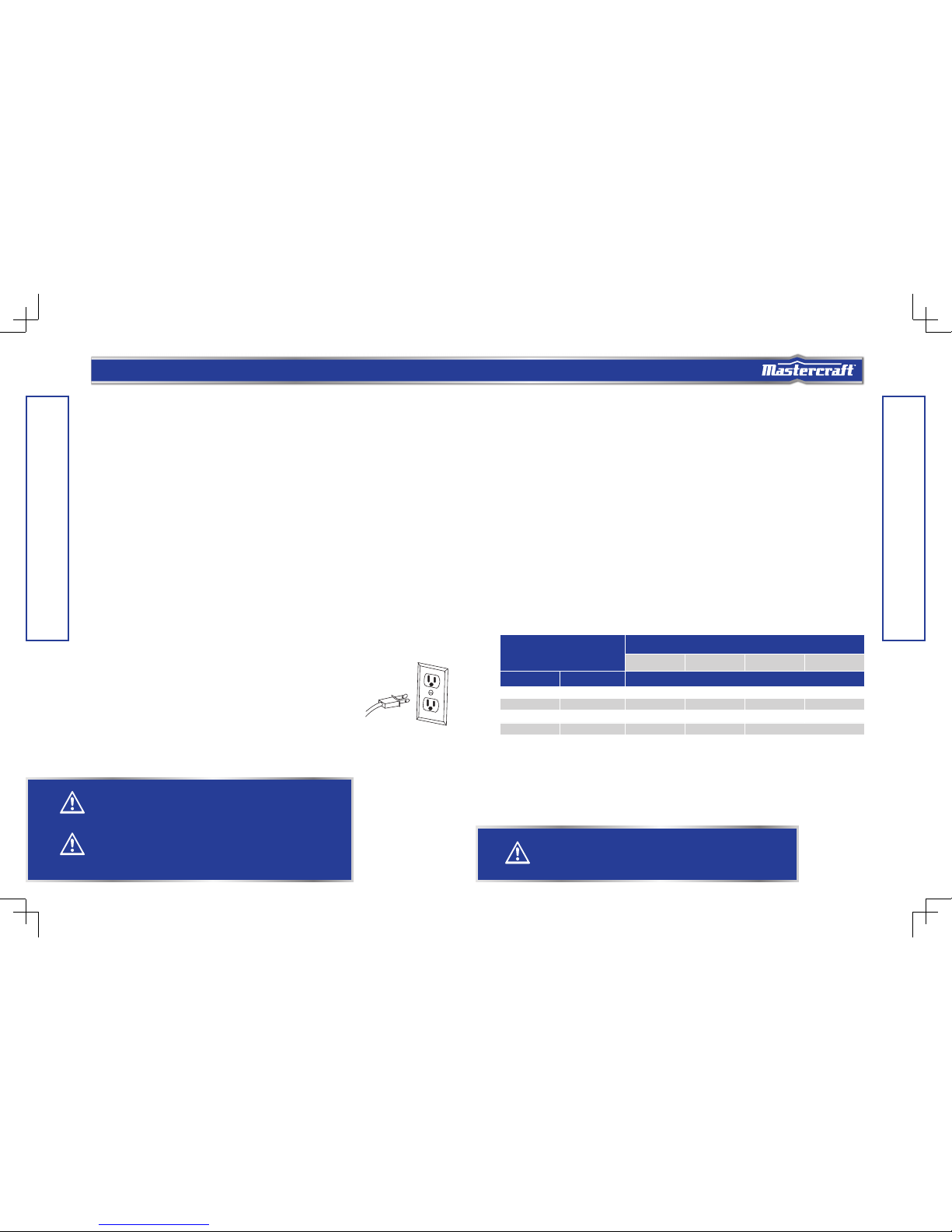
ELECTRICAL SAFETY
• To reduce the risk of electric shock, double-insulated tools are equipped with a polarized
plug (one blade is wider than the other). This plug will fit into a polarized outlet only one way. If
the plug does not fit into the outlet properly, reverse the plug. If it still does
not fit, contact a qualified electrician to install a polarized outlet. Do not
change the plug in any way.
• Double insulation eliminates the need for the three-wire grounded
power cord and grounded power supply system. This compound
mitre saw is a double-insulated tool.
• Before plugging in the tool, BE SURE that the outlet voltage
supplied is within the voltage marked on the tool’s data plate. DO NOT use “AC only” rated
tools with a DC power supply.
• Avoid body contact with grounded surfaces such as pipes, radiators, ranges and
refrigerators. There is an increased risk of electric shock if your body is grounded.
• DO NOT expose power tools to rain or wet conditions and do not use power tools in wet
or damp locations. Water entering a power tool will increase the risk of electric shock. This tool is
intended for indoor use only.
• If operating a power tool in damp locations is unavoidable, ALWAYS USE a power supply for
your tool that is protected by a Ground Fault Circuit Interrupter. ALWAYS WEAR electrician’s
rubber gloves and footwear in damp conditions.
• Inspect tool cords for damage. Have damaged tool cords repaired by a qualied person. BE
SURE to stay constantly aware of the cord location, and keep it well away from the moving blade.
• Do not abuse the cord. Never use the cord for carrying, pulling or unplugging the power
tool. Keep cord away from heat, oil, sharp edges and moving parts. Replace damaged cords
immediately. Damaged cords increase the risk of electric shock.
• Use proper extension cord. Make sure your extension cord is in good condition. When using an
extension cord, be sure to use one heavy enough to carry the current your product will draw. An
undersized cord will cause a drop in line voltage resulting in loss of power and overheating. The
following table shows the correct size to use depending on cord length and nameplate ampere rating.
If in doubt, use the next heavier gauge. The smaller the gauge number, the heavier the cord.
MINIMUM GAUGE FOR CORD SETS
Ampere rating of the tool
(120 V circuit only)
Total length of cord
25′′ (7.62 m) 50′′ (15.24 m) 100′ (30.48 m) 150′ (45.72 m)
more than not more than Minimum Gauge for the extension cord (AWG)
0 6 18 16 16 14
6 10 18 16 14 12
10 12 16 16 14 12
12 16 14 12 Not recommended
SPECIFIC SAFETY RULES FOR MITRE SAWS
• Always wear eye protection.
• Do not operate the saw without guards in place.
WARNING!
Do not permit fingers to touch the terminal or plug when installing or removing the plug from an
outlet.
WARNING!
For your own safety, read the Instruction Manual before operating the mitre saw.
WARNING!
Double insulation DOES NOT take the place of normal safety precautions when operating this tool.
Page 5

8 9
model no. 055-6761-2 | contact us 1-800-689-9928
SAFETY GUIDELINES
SAFETY GUIDELINES
• Be sure to turn the tool off and wait for the saw blade to stop before moving the workpiece or
changing settings.
• Be sure that the power is disconnected before changing the blade or servicing the saw.
• Do not expose to rain or use in a damp location.
• When servicing, use only identical replacement parts.
• Never reach around the saw blade.
• Do not perform any operation freehand. Always place the workpiece to be cut on the mitre saw
table and position it firmly against the fence as a backstop. Always use the fence.
• Always keep hands out of the path of the saw blade. Do not reach under the material being cut
or into the blade’s cutting path with your fingers or hand for any reason.
• To reduce the risk of injury, return the cutting head to the full rear position after each crosscut
operation.
• Always make sure that the mitre table and head assembly (bevel function) are locked in
position before operating your saw. Lock the mitre table by securely tightening the mitre locking
handle. Lock the head assembly (bevel function) by securely tightening the bevel locking knob.
• Be sure the blade path is free of nails. Always carefully inspect lumber and remove all nails
BEFORE cutting.
• Always be sure the blade clears the workpiece. Never start the saw with the blade touching the
workpiece. Always allow the motor to come up to full speed before starting a cut.
• Support long workpieces when cutting to minimize the risk of blade pinching or kickback.
The saw may slip, walk or slide while cutting long or heavy boards.
• Never use a length-stop on the free end of a clamped workpiece. Never hold onto or bind the
free end of the workpiece in any operation. If a clamp and length-stop are used together, they must
both be installed on the same side of the saw table to prevent the saw from catching the loose end and
kicking up.
• Never cut more than one piece at a time. Do not stack more than one workpiece on the worktable
at a time.
• Avoid awkward operations and hand positions where a sudden slip could cause your hand
to hit the blade. Always make sure you have good balance. Never operate your saw on the floor or in
a crouched position.
• Only use the correct blades. Use the correct blade size, style and cutting speed for the material and
the type of cut. Do not use blades with incorrect size holes. NEVER use blade washers or blade bolts
that are defective or incorrect. The maximum blade capacity for this saw is 7 1/4” (18.4 cm).
• Always keep blades clean, sharp and properly set. Sharp blades minimize stalling and kickback.
• Do not use dull or damaged blades. Bent blades can break easily or cause kickback.
• Never hold a workpiece by hand if it is too small to be clamped. Always keep your hands clear
of the “no hands” zone.
• Never apply lubricants to the blade when it is running.
• Never use solvents to clean plastic parts. Solvents could dissolve or otherwise damage the
material.
• Do not turn the motor switch on and off rapidly. This could cause the blade to loosen, which
could create a hazard. Should this ever occur, stand clear and allow the saw blade to come to a
complete stop. Disconnect the saw from the power source and tighten the blade bolt securely.
• Never leave the saw unattended while it is connected to a power supply.
• Keep the motor air slots clean and free of chips or dust. To avoid motor damage, the motor
should be blown out or vacuumed frequently. This keeps sawdust from interfering with the motor
ventilation.
• Never lift this tool by gripping the switch handle or by the mitre fence. This may cause
misalignment. Always lock the head assembly in the “Down” position and carry the saw by holding the
base or lift it using the carrying handle/support bracket.
ADDITIONAL RULES FOR SAFE OPERATION
• Know your power tool. Read the instruction manual carefully. Learn the applications and limitations,
as well as the specific potential hazards related to this tool. Following these rules will reduce the risk of
electric shock, fire or serious injury.
• Always wear safety glasses or eye shields when using this saw. Everyday eyeglasses have
only impact-resistant lenses; they are NOT safety glasses. All users and bystanders MUST wear eye
protection that conforms to ANSI Z87.1.
• Protect your lungs. Wear a face mask or a dust mask if the operation is dusty.
• Protect your hearing. Wear appropriate personal hearing protection during use. Under some
conditions and duration of use, noise from this product may contribute to hearing loss.
• All visitors and bystanders must wear the same safety equipment that the operator of the
saw wears.
• Inspect the tool cords periodically and, if damaged, have them repaired by a qualified person.
• Always check the tool for damaged parts. Before further use of the tool, a guard or other part that
is damaged should be carefully checked to determine whether it will operate properly and perform
its intended function. Check for misalignment or binding of moving parts, broken parts and any other
WARNING!
The use of this tool can generate and/or disburse dust, which may cause serious and permanent
respiratory or other injury. Always use NIOSH/OSHA approved respiratory protection appropriate
for dust exposure. Direct particles away from the face and body.
Page 6
10 11
model no. 055-6761-2 | contact us 1-800-689-9928
SAFETY GUIDELINES
KEY PARTS DIAGRAM
condition that may affect the tool’s operation. A guard or other part that is damaged should be properly
repaired or replaced by a qualified person.
• Save these instructions. Refer to them frequently and use them to instruct others who may
use this tool. If someone borrows this tool, make sure he or she has these instructions.
GLOSSARY OF WOODWORKING TERMS
• Spindle: The revolving shaft on which a blade or cutting tool is mounted.
• Spindle Lock: Allows the user to stop the blade from rotating while tightening or loosening the blade
screw during blade replacement or removal.
• Bevel Cut: A cutting operation made with the blade at any angle other than 90° to the mitre table.
• Chamfer Cut: A cut removing a wedge from a block of wood so the end (or part of the end) is angled
other than at 90°.
• Compound Mitre Cut: A cut made using both a mitre angle and a bevel angle at the same time.
• Crosscut: A cutting operation made across the grain of the workpiece.
• Freehand Cut: Performing a cut without using a fence, mitre gauge, fixture, work clamp, or other
proper device to keep the workpiece from twisting or moving during the cut. Do not perform any
operation freehand. Use a clamp or vice wherever possible.
• Kerf: The material removed by the blade in a through cut or the slot produced by the blade in a
non-through or partial cut.
• Kickback: A hazard that can occur when the blade binds or stalls, throwing the workpiece back
toward the operator.
• Mitre Cut: A cutting operation made with the blade at any angle other than 90° to the fence.
• No-Hands Zone: The area between the marked lines on the left and right side of the mitre table base.
This zone is identified by No-Hands Zone symbols inside the lines marked on the mitre table base.
• Non-through Cut: Any cutting operation where the blade does not extend completely through the
thickness of the workpiece.
• Revolutions Per Minute (RPM): The number of turns completed by a spinning object in one minute.
• Saw Blade Path: The area over, under, behind or in front of the blade, as it applies to the workpiece;
the area that will be or has been cut by the blade.
• Set: The distance that the saw blade tooth is bent (or set) outward from the face of the blade.
• Throat plate: A plate inserted in the mitre saw’s table that allows for blade clearance.
• Through Sawing: Any cutting operation where the blade extends completely through the thickness of
the workpiece.
• Workpiece or Material: The item on which the cutting operation is being done. The surfaces of a
workpiece are commonly referred to as faces, ends and edges.
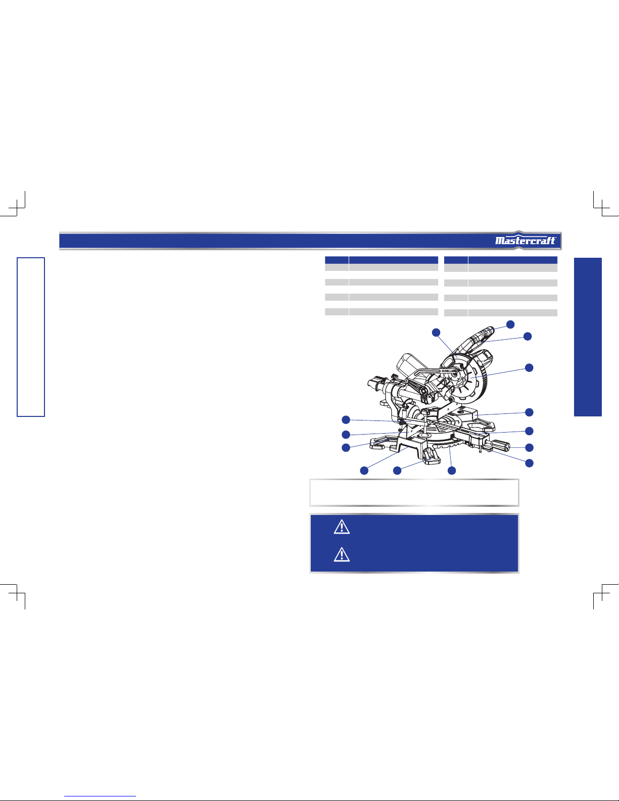
NOTE:
Before attempting to use your saw, familiarize yourself with all of the operating features and
safety requirements.
No. Description
1 Switch handle
2 On/Off trigger switch
3 Upper blade guard
4 Lower blade guard
5 Base
6 Table insert
7 Mitre handle
No. Description
8 Mitre stop locking lever
9 Positive mitre stop
10 Mounting hole
11 Hex wrench
12 Fence
13 Work clamp
14 Handhold for transportation
WARNING!
Carefully remove the tool and any accessories from the box. Make sure that all items listed in
the packing list are included. Inspect the tool carefully to make sure that no breakage or damage
occurred during shipping.
WARNING!
Do not discard the packing material until you have carefully inspected and satisfactorily operated
the tool.
1
2
3
4
5
6
7
8
12
13
11
910
14
Page 7

12 13
model no. 055-6761-2 | contact us 1-800-689-9928
KEY PARTS DIAGRAM
ASSEMBLY AND ADJUSTMENTS
REMOVING AND INSTALLING THE BLADE
Removing blade
(Fig. 1 to 4)
• Unplug the tool from the power source.
• Adjust the lock-down pin to raise the cutting head.
• Loosen the cover plate screw (1) about 4 turns with a
star-head screwdriver. Do not remove this screw from
the tool.
• Lift and hold up the lower blade guard (2) to expose
the threaded blade bolt (3).
• Press and hold the spindle-lock button (4) and
rotate the blade at the same time, until it is locked
in position.
• Continue to hold the spindle lock button to keep it
engaged, while using the wrench to turn the threaded
blade bolt clockwise and remove the threaded blade
bolt.
• Remove the outer flange (5) and the blade (6). Wipe
the flanges and spindle to remove any dust and debris.
Installing blade (Fig. 1 to 4)
Unplug the mitre saw before changing/installing the blade.
• Install a 7 1/4” (18.4 cm) blade with 5/8” (15.9 mm) arbor onto the arbor shaft (7). Match the arrow
on the blade with the arrow on the upper blade guard. Make sure that the blade teeth are pointing
downward.
No. Description
15 Spindle lock
16 Blade
17 Motor
18 Dust bag
19 Lock-down pin
No. Description
20 Sliding carriage lock knob
21 Bevel lock knob
22 Bevel scale
23 Table
24 Mitre scale
WARNING!
Always be sure that the tool is switched off and unplugged before adjusting or checking function
on the tool. Failure to switch off and unplug the tool may result in serious personal injury from
accidental start-up.
WARNING!
Only use a 7 1/4” (18.4 cm) diameter blade. To avoid injury from an accidental start, make sure
the switch is in the OFF position and the plug is not connected to the power source outlet.
NOTE:
Pay attention to the pieces being removed, noting their position and the direction they face. Wipe the blade
collar clean of any sawdust before installing a new blade.
WARNING!
Your saw should NEVER be connected to the power source when you are assembling
parts, making adjustments, installing or removing blades, cleaning, or when it it not in use.
Disconnecting the saw will prevent accidental starting, which could cause serious personal injury.
WARNING!
Do not allow familiarity with the mitre saw to cause a lack of alertness. A fraction of a second of
carelessness is enough to cause severe injury.
1
2
3
15
16
17
24
18
19
21
22
23
20
Page 8

14 15
model no. 055-6761-2 | contact us 1-800-689-9928
• Place the out flange against the blade and on the
arbor. Thread the blade bolt onto the arbor in a
counter-clockwise direction.
• Place the blade hex wrench into the blade bolt.
• Press the spindle lock button, holding it in firmly while
turning the blade counterclockwise. When spindle
lock engages, continue to press it in while tightening
the blade bolt securely.
• Rotate the lower blade guard back to its original
position until the slot in the cover plate engages with
the cover plate screw. While holding the lower blade
guard, tighten the screw with a Phillips screwdriver.
• Verify that the operation of the guard does not bind or
stick.
• Be sure the spindle lock is released so the blade turns
freely before operating the saw.
INSTALLING THE DUST BAG (Fig. 5)
• Squeeze the metal collar wings on the dust bag.
′• Place the dust bag neck opening around the exhaust
port on the mitre saw and release the metal collar
wings.
MITRE SCALE (Fig. 6)
The sliding compound mitre saw scale can be easily read,
showing mitre angles from 0° to 45° to the left, and 0°
to 45° to the right. The mitre saw table has nine of the
most common angle settings with positive stops at 0°,
15°, 22.5°, 31.6° and 45°. These positive stops position
the blade at the desired angle quickly and accurately.
Follow the process below for quickest and most accurate
adjustments.
This tool is carefully adjusted and aligned at the factory,
but rough handling may have affected the alignment. If
your tool is not aligned properly, perform the following as
needed.
To Adjust Mitre Angles:
• Unlock the table by turning the mitre handle (1)
counterclockwise.
• Move the table while lifting up on the positive stop locking lever (2) to align the indicator (3) to the
desired degree measurement.
• If the desired angle is one of the nine positive stops, release the positive stop locking lever, making
sure the lever snaps into position, and then secure by tightening the mitre handle.
• If the mitre angle desired is not one of the nine positive stops, simply lock the table into desired angle
position by turning the mitre handle in the clockwise direction.
ASSEMBLY AND ADJUSTMENTS
NOTE:
The lower blade guard must be in the right position to access the cover plate screw.
NOTE:
To empty the dust bag, remove it from exhaust port. Open zipper on underside of bag and empty into waste
container.
IMPORTANT:
Make sure the flats of the out flange are engaged with the flats on the arbor shaft. Also, the flat side of the
out flange collar must be placed against the blade.
IMPORTANT:
Check bag frequently and empty it before it gets full.
ASSEMBLY AND ADJUSTMENTS
WARNING!
• To avoid injury, never use the saw without the cover plate securely in place. It keeps the
blade bolt from falling out if it accidentally loosens and helps prevent the spinning blade from
coming off the saw.
• Make sure the anges are clean and properly arranged. Lower the blade into the lower table
and check for any contact with the metal base or the mitre table.
• To avoid injury from an accidental start, make sure the switch is in the OFF position and the
plug is not connected to the power source outlet.
• Never cut metals or masonry products with this tool. This mitre saw is designed for use on
wood and wood-like products only.
WARNING!
Do not use this saw to cut and/or sand metals. The hot chips or sparks may ignite sawdust from
the bag material.
3
5
6
Blade bolt
Out flange
Inner flange
Sawblade
Arborshaft
7
1
2
4
3
4
Page 9

16 17
model no. 055-6761-2 | contact us 1-800-689-9928
• If the blade is not 90° square with the table, loosen the bevel lock knob, tilt the cutting head to the left,
loosen the locknut (3) and turn the bevel angle adjustment bolt (4) in or out with a 3 mm hex wrench
until the blade is square with the table.
• Tilt the pivot arm back to the right at 90° (0°) bevel and recheck for alignment.
• Repeat steps if further adjustment is needed.
• Tighten bevel lock knob and locknut (3) when
alignment is achieved.
90° Bevel Pointer Adjustment (FIG. 9)
′When the blade is exactly 90° to the table, loosen the bevel
indicator screw (1) using a star-head screwdriver.
• Adjust bevel indicator (2) to the “0” mark on the bevel
scale and retighten the screw.
45° Bevel Adjustment (FIG. 10)
• Loosen the bevel lock knob (1) and tilt the cutting
head completely to the left.
• Using a combination square, check to see if the blade
is at a 45° angle to the table.
• If the blade is not at 45° to the mitre table, tilt the
pivot arm to the right, loosen the locknut (2) on the
bevel angle adjustment bolt (3) and use a 3 mm hex
wrench to the adjust bolt depth in or out to increase or
decrease the bevel angle.
• Tilt the cutting arm to the left to 45° bevel and
recheck for alignment.
• Repeat steps until the blade is at 45° to the mitre
table.
• Tighten bevel lock knob and locknut when alignment
is achieved.
MAXIMUM CUTTING DEPTH (FIG. 11)
The maximum depth travel of the cutting head was set at
the factory. Check to see that the blade does not extend
more than 5/16” (0.8 cm) below the table insert, and does
not touch the control arm throat or any part of the base or
table. If the maximum depth needs readjusting:
Mitre Angle Pointer Adjustment (Fig. 6)
• Move the table to the 0° positive stop.
• Loosen the screw (4) that holds the indicator with a Phillips screwdriver.
• Adjust the indicator (3) to the 0° mark and retighten the screw.
ADJUSTING FENCE SQUARENESS (Fig. 7)
• Lower the cutting head and lock in position.
• Using a square (1), lay the heel of the square against
the blade and the ruler against the fence (2) as
shown.
• Loosen the two fence locking bolts (3) with a 6 mm
hex wrench.
• Adjust the fence 90° to the blade and tighten the two
fence locking bolts.
• After fence has been aligned, make a cut at 90° using
a scrap piece of wood and check squareness on the
piece. Readjust if necessary.
BEVEL STOP ADJUSTMENT
This tool is carefully adjusted and aligned at the factory,
but rough handling may have affected the alignment. If
your tool is not aligned properly, perform the following as
needed.
90° (0°) Bevel Adjustment (Fig. 8)
• Loosen bevel lock knob (1) and tilt the pivot arm
completely to the right. Tighten the bevel lock knob.
• Place a combination square (2) on the mitre table with
the ruler against the table and the heel of the square
against the saw blade.
ASSEMBLY AND ADJUSTMENTS
ASSEMBLY AND ADJUSTMENTS
WARNING!
To avoid injury from an accidental start, make sure the switch is in the OFF position and the plug
is not connected to the power source outlet.
WARNING!
To reduce the risk of injury, wear safety goggles or glasses with side shields.
1
2
1
3
2
1
2
3 3
1
4
2
3
2
3
1
Page 10

18 19
model no. 055-6761-2 | contact us 1-800-689-9928
OPERATING INSTRUCTIONS
UNLOCKING AND LOCKING THE CUTTING
HEAD (Fig. 12)
To unlock: Press and lightly hold down the cutting head.
Pull out the lock-down pin (1) to release the cutting head.
The cutting head should freely move up.
To lock: Place the cutting head at the lowest position.
Secure the position and push the stop lock pin into the
locking position. Please note, if there is any cutting depth
setting, the lock in may not work. Release the cutting depth
limitation, and then lock the cutting head in.
UNLOCKING THE SLIDE CARRIAGE (Fig. 13)
After removing the saw from the carton, loosen the slide
carriage lock knob (1). When transporting or storing the
mitre saw, the slide carriage should always be locked in
position. The slide carriage lock knob is located on the
upper side of the slide carriage.
IMPORTANT:
To avoid damage, never carry the mitre saw by the switch handle, the cutting arm or the mitre table handle.
ALWAYS use the handholds for transportation.
CAUTION!
To avoid injury and damage to the saw, transport and store the mitre saw with the cutting head
locked in the down position. Never use the stop pin to hold the cutting head in a down position for
cutting operations.
• Loosen the lock nut (1) to free the depth screw (2).
• Move the cutting head down until the blade extends just 5/16” (0.8 cm) below the table insert.
• Adjust the depth screw to touch the stop plate (3), then tighten the lock nut to secured the depth
screw.
• Recheck the blade depth by moving the cutting head front to back through the full motion of a cut
along the control arm. If the blade touches the inside of the control arm, readjust the setting.
• When it is properly set, tighten the lock nut to lock the depth screw.
ASSEMBLY AND ADJUSTMENTS
CAUTION!
Always make sure that the spindle lock button is released so the blade can rotate freely. MAKE
SURE that the locking pin is loose and the cutting head moves freely up and down. ENSURE that
all clamps and locks are tightly in place, and that there is no excessive play in any parts.
WARNING!
Before each use, verify that the blade is free of cracks, loose teeth, missing teeth, or any other
damage. Do not use if damage is observed or suspected.
Always wait for the blade to stop completely, and unplug the tool before changing accessories or
making adjustments.
1
1
Page 11

20 21
model no. 055-6761-2 | contact us 1-800-689-9928
BENCH MOUNTING
(Fig. 14)
This tool should be bolted with four bolts to a level and
stable surface using the bolt holes (1) provided in the tool’s
base. This will help prevent tipping and possible injury.
INSTALLING THE WORK CLAMP (Fig. 15)
There are two mounting holes for the work clamp. These
are located just behind the fence on the left and right side
of the base.
•
Loosen the locking screw with a Phillips screwdriver.
• Place the work clamp in the desired mounting hole.
• Tighten the screw to hold the work clamp.
ON/OFF TRIGGER SWITCH (Fig. 16)
To turn the saw on, depress the trigger switch. To turn
the tool off, release the switch. There is no provision for
locking the switch on. To lock the saw off, place a padlock
in the hole provided in the trigger switch.
When the trigger switch is released, the blade will be
stopped within 10 seconds.
DRY RUN
For safe operation, it’s necessary to know where the blade
will contact the workpiece during the cutting process.
Always perform the simulated cutting process with the
switch off to check and understand the projected path of
the saw blade. Adjust the work clamps and fences to avoid
any contact with the lower guard and cutting action.
MITRE CUT (Fig. 17)
• When a mitre cut is required, unlock the table by
turning the mitre handle (1) counter-clockwise.
• While holding the mitre handle, lift up on the positive
stop locking lever (2).
• Rotate the table to the right or left with the mitre
handle.
• When the table is in the desired position, as shown
on the mitre scale (3), release the positive stop
locking lever and tighten the mitre handle. The table
is now locked at the desired angle. Positive stops are
provided at 0°, 15°, 22.5°, 31.6° and 45°.
BEVEL CUT (Fig. 18)
• When a bevel cut is required, loosen the bevel lock
knob (1) by turning it clockwise.
• Tilt the cutting head to the desired angle, as shown on
the bevel scale (2).
• The blade can be positioned at any angle, from a
90° straight cut (0° on the scale) to a 45° left bevel.
Tighten the bevel lock knob to lock the cutting head in
position. Positive stops are provided at 0° and 45°.
COMPOUND CUT (Fig. 19)
A compound cut is the combination of a mitre and a bevel
cut simultaneously.
• Loosen the bevel lock knob (1) and position the cutting
head at the desired bevel position. Lock the bevel lock
knob.
• Loosen the mitre handle (2). Lift up the positive stop
locking lever (3) and position the table at the desired
angle. Release the positive stop locking lever and lock
the mitre handle.
OPERATING INSTRUCTIONS
WARNING!
Ensure that the tool will not move on the supporting surface. Movement of the mitre saw on the
supporting surface while cutting may result in loss of control and serious personal injury.
WARNING!
• To avoid injury, after completing a cut and releasing the trigger switch, wait and conrm that
the blade has stopped before raising the cutting head.
′• To avoid injury, check and tighten the blade bolt periodically.
OPERATING INSTRUCTIONS
IMPORTANT:
Always tighten the mitre table lock handle before performing every cutting operation.
2
1
1 1
1 1
1
2
3
2
3
1
Page 12

1
2
3
4
22 23
model no. 055-6761-2 | contact us 1-800-689-9928
SLIDING CARRIAGE SYSTEM
(Fig. 20)
• For chop cutting operations on small workpieces,
slide the cutting head completely toward the rear of
the unit and tighten the carriage lock knob (1).
• To cut wide boards up to 8” (20.3 cm), the carriage
lock knob must be loosened to allow the cutting head
to slide freely.
SLIDE CUTTING WIDE BOARDS UP TO
8” (20.3 cm) WIDE
To avoid injury:
• Let the blade reach full speed before cutting. This will help reduce the risk of a thrown workpiece.
• Do not make crosscuts by lowering the blade and pulling the cutting head through the wood
toward you.
To Slide Cut Wide Boards (Fig. 21)
• Unlock the carriage lock knob (1) and allow the
cutting head assembly to move freely.
• Set both the desired bevel angle and/or the mitre
angle and lock into position.
• Use a work clamp (2) to secure the workpiece (3).
• Grasp and pull the switch handle (4) forward until
the centre of the saw blade is over the front of the
workpiece.
• Engage the trigger to turn the saw on.
• When the saw reaches full speed, slowly push the switch handle down, cutting through the leading
edge of the workpiece.
• Slowly move the switch handle toward the fence, completing the cut.
• Release the trigger and allow the blade to stop spinning before raising the cutting head and removing
the workpiece.
SETTING CUTTING DEPTH (Fig. 22)
The depth of cut can be preset for even and repetitive
shallow cuts.
• Slide the stop plate (1) towards the front position.
• Loosen the lock nut (2) to free the lock knob (3), turn
the stop knob until the cutting head down until the
teeth of the blade are at the desired depth.
• While holding the upper arm in that position, tighten
the lock nut to secured the stop knob.
• Recheck the blade depth by moving the cutting head
front to back through the full motion of typical cut
along the control arm.
CUTTING GROOVES (Fig. 23)
• Mark lines to identify the width and depth of the
desired cut on the workpiece and put the workpiece
on the table and aim the inside tip of the blade at the
line. Use a work clamp to secure the workpiece on the
table.
• Lower the cutting head so the tip of the blade touches
the top surface of the workpiece at the marked line.
• While holding the upper arm in position, loosen the
lock nut and turn the stop knob until it touches the
stop plate, then retighten the lock nut. (SEE “SETTING
CUTTING DEPTH”)
• Cut two parallel grooves as shown.
• Use a wood chisel or make multiple passes with a router to remove the material between the two
outside grooves to create the groove.
OPERATING INSTRUCTIONS
CAUTION!
To reduce the risk of injury, return carriage to the full rear position after each crosscut operation.
CAUTION!
Always use a work clamp to maintain control and reduce the risk of workpiece damage and
personal injury.
WARNING!
DO NOT USE A DADO BLADE, use only the standard saw blade for this operation.
OPERATING INSTRUCTIONS
NOTE:
Always perform a dry run cut so you can determine if the operation being attempted is possible before
power is applied to the saw.
1
2
3
1
Page 13

24 25
model no. 055-6761-2 | contact us 1-800-689-9928
CUTTING WARPED MATERIAL
(Fig. 24)
When cutting warped material, be sure that the convex
side is against the fence. If the workpiece is placed with
the concave side facing the fence, it will pinch the blade
near the completion of the cutting.
AUXILIARY WOOD FENCE (Fig. 25)
When making multiple or repetitive cuts that result in
cut-off pieces of 1” (2.5 cm) or less, it is possible for the
saw blade to catch the cut-off piece and throw it out of the
saw or into the blade guard and housing, possibly causing
damage or injury. To minimize this, an auxiliary wood fence
can be mounted to your saw. Holes are provided in the
saw fence to attach an auxiliary wood fence (this provides
additional depth of cut). This fence should be constructed
of straight auxiliary wood approximately 3/4” (1.9 cm)
thick by 1 1/2” (3.8 cm) high by 16” (40.6 cm) long. Attach
the wood fence securely and make a full depth cut to
make a blade slot. Check for interference between the
wood fence and the lower blade guard. Adjust if necessary.
CUTTING BASE MOULDING (Fig. 26)
Base mouldings and many other mouldings can be cut
on a compound mitre saw. The setup of the saw depends
on moulding characteristics and applications, as shown.
Perform practice cuts on scrap material to achieve best
results:
• Always make sure mouldings rest firmly against
the fence and table. Use hold-down or C-clamps,
whenever possible, and place tape on the area being
clamped to avoid marks.
• Reduce splintering by taping the cut area prior to
making cut. Mark cut line directly on the tape.
• Splintering typically happens due to wrong blade application and thinness of the material.
OPERATING INSTRUCTIONS
NOTE:
Always perform a dry run cut so you can determine if the operation being attempted is possible before
power is applied to the saw.
OPERATING INSTRUCTIONS
CUTTING CROWN MOULDING (Fig. 27, 28)
Your compound mitre saw is suited for the difcult task of
cutting crown moulding. To t properly, crown moulding
must be compound-mitreed with extreme accuracy. The
two surfaces on a piece of crown moulding that t at
against the ceiling and wall are at angles that, when added
together, equal exactly 90°.
Most crown moulding has a top rear angle (the section that
ts at against the ceiling) of 52° and a bottom rear angle
(the section that ts at against the wall) of 38°.
In order to accurately cut crown moulding for a 90° inside
or outside corner, lay the moulding with its broad back
surface at on the saw table. When setting the bevel and
mitre angles for compound mitres, remember the settings
are interdependent; changing one changes the other, as
well.
Bevel/Mitre Settings (when the angle between the walls equals 90°)
KEY BEVEL SETTING Mitre SETTING TYPE OF CUT
Inside corner - Left side
IL 33.9° 31.6° Right 1. Position top of moulding against fence.
2. Mitre table set at RIGHT 31.6°.
3. LEFT side is finished piece.
Inside corner - Right side
IR 33.9° 31.6° Left 1. Position bottom of moulding against
fence.
2. Mitre table set at LEFT 31.6°.
3. LEFT side is finished piece.
Outside corner - Left side
OL 33.9° 31.6° Left 1. Position bottom of moulding against
fence.
2. Mitre table set at LEFT 31.6°.
3. RIGHT side is finished piece.
Outside corner - Right side
OR 33.9° 31.6° Right 1. Position top of moulding against fence.
2. Mitre table set at RIGHT 31.6°.
3. RIGHT side is finished piece.
IL
IR
OL
OR
Inside
Corner
Outside
Corner
Fence
Mitre saw table
Workpiece
Mitre at 45°
bevel at 0°
Fence
Mitre saw table
Mitre at 0°
bevel at 45°
Workpiece
Fence
Mitre saw table
Workpiece
Fence
Mitre saw table
Workpiece
Page 14

26 27
model no. 055-6761-2 | contact us 1-800-689-9928
OPERATING INSTRUCTIONS
OPERATING INSTRUCTIONS
52/38° CROWN MOULDING 45/45° CROWN MOULDING
Angle Between
Walls
Mitre Setting Bevel Setting Mitre Setting Bevel Setting
104 25.69 29.02 28.92 25.81
105 25.29 28.67 28.48 25.50
106 24.89 28.31 28.05 25.19
107 24.49 27.96 27.62 24.87
108 24.10 27.59 27.19 24.56
109 23.71 27.23 26.77 24.24
110 23.32 26.87 26.34 23.93
111 22.93 26.51 25.92 23.61
112 22.55 26.15 25.50 23.29
113 22.17 25.78 25.08 22.97
114 21.79 25.42 24.66 22.66
115 21.42 25.05 24.25 22.33
116 21.04 24.68 23.84 22.01
117 20.67 24.31 23.43 21.68
118 20.30 23.94 23.02 21.36
119 19.93 23.57 22.61 21.03
120 19.57 23.20 22.21 20.70
121 19.20 22.83 21.80 20.38
122 18.84 22.46 21.40 20.05
123 18.48 22.09 21.00 19.72
124 18.13 21.71 20.61 19.39
125 17.77 21.34 20.21 19.06
126 17.42 20.96 19.81 18.72
127 17.06 20.59 19.42 18.39
128 16.71 20.21 19.03 18.06
129 16.37 19.83 18.64 17.72
130 16.02 19.45 18.25 17.39
131 15.67 19.07 17.86 17.05
132 15.33 18.69 17.48 16.71
133 14.99 18.31 17.09 16.38
134 14.66 17.93 16.71 16.04
135 14.30 17.55 16.32 15.70
136 13.97 17.17 15.94 15.36
137 13.63 16.79 15.56 15.02
138 13.30 16.40 15.19 14.62
139 12.96 16.02 14.81 14.34
140 12.63 15.64 14.43 14.00
141 12.30 15.25 14.06 13.65
142 11.97 14.87 13.68 13.31
143 11.64 14.48 13.31 12.97
144 11.31 14.09 12.94 12.62
145 10.99 13.71 12.57 12.29
CROWN MOULDING CHART
To aid in the correct setting, the compound angle setting chart below has been
provided.
52/38° CROWN MOULDING 45/45° CROWN MOULDING
Angle Between
Walls
Mitre Setting Bevel Setting Mitre Setting Bevel Setting
67 42.93 41.08 46.89 36.13
68 42.39 40.79 46.35 35.89
69 41.85 40.50 45.81 35.64
70 41.32 40.20 45.28 35.40
71 40.79 39.90 44.75 35.15
72 40.28 39.61 44.22 34.89
73 39.76 39.30 43.70 34.64
74 39.25 39.00 43.18 35.38
75 38.74 38.69 42.66 34.12
76 38.24 38.39 42.15 33.86
77 37.74 38.08 41.64 33.60
78 37.24 37.76 41.13 33.33
79 36.75 37.45 40.62 33.07
80 36.27 37.13 40.12 32.80
81 35.79 36.81 39.62 32.53
82 35.31 36.49 39.13 32.25
83 34.83 36.17 38.63 31.98
84 34.36 35.85 38.14 31.70
85 33.90 35.52 37.66 31.42
86 33.43 35.19 37.17 31.34
87 32.97 34.86 36.69 30.86
88 32.52 34.53 36.21 30.57
89 32.07 34.20 35.74 30.29
90 31.62 33.86 35.26 30.00
91 31.17 33.53 34.79 29.71
92 30.73 33.19 34.33 29.42
93 30.30 32.86 33.86 29.13
94 29.86 32.51 33.40 28.83
95 29.43 32.17 32.94 28.54
96 29.00 31.82 32.48 28.24
97 28.58 31.48 32.02 27.94
98 28.16 31.13 31.58 27.64
99 27.74 30.78 31.13 27.34
100 27.32 30.43 30.68 27.03
101 26.91 30.08 30.24 26.73
102 26.50 29.73 29.80 26.42
103 26.09 29.38 29.36 26.12
Page 15

28 29
model no. 055-6761-2 | contact us 1-800-689-9928
SAWDUST
Periodically, sawdust will accumulate under the table and base. This could cause difculty in the movement
of the table when setting up a mitre cut. Frequently blow out or vacuum up the sawdust.
LOWER BLADE GUARD
Do not use the saw without the lower blade guard.
The lower blade guard is attached to the saw for your protection. Should the lower guard become damaged,
do not use the saw until the damaged guard has been replaced. Check regularly to make sure the lower
guard is working properly. Clean the lower guard of any dust or buildup with a damp cloth.
REPLACING CARBON BRUSHES (Fig. 29)
Replace both carbon brushes when either has less than
1/4” (0.6 cm) length of carbon remaining, or if the spring or
wire is damaged or burned. To inspect or replace brushes,
rst unplug the saw. Remove the two screws on the back
cover of the motor and take the cover off. Move the coil
spring which press on the carbon brush to other side to
free the carbon brush. Pull out the brush and the wire
which connect to the holder. Replace it for a new carbon
brush. When replace for the other side. To reassemble,
reverse the procedure. Tighten two screws on the back
cover.
OPERATION INSTRUCTIONS
MAINTENANCE
WARNING!
• To avoid re or toxic reaction, never use gasoline, naphtha acetone, lacquer thinner or similar
highly volatile solvents to clean the mitre saw.
• To avoid injury from unexpected starting or electrical shock, unplug the power cord before
working on the saw.
• For your safety, this saw is double-insulated. To avoid electrical shock, re or injury, use
only parts identical to those identied in the parts list. Reassemble exactly to avoid electrical
shock.
CAUTION!
If blowing sawdust, wear proper eye protection to keep debris from blowing into eyes.
CAUTION!
• Do not use solvents on the guard. They could make the plastic cloudy and brittle.
• When cleaning the lower guard, unplug the saw to avoid unexpected start-up.
NOTE:
To reinstall the same brushes, first make sure the brushes go back in the way they came out.
52/38° CROWN MOULDING 45/45° CROWN MOULDING
Angle Between
Walls
Mitre Setting Bevel Setting Mitre Setting Bevel Setting
146 10.66 13.32 12.20 11.93
147 10.34 12.93 11.83 11.59
148 10.01 12.54 11.46 11.24
149 9.69 12.16 11.09 10.89
150 9.37 11.77 10.73 10.55
151 9.05 11.38 10.36 10.20
152 8.73 10.99 10.00 9.85
153 8.41 10.60 9.63 9.50
154 8.09 10.21 9.27 9.15
155 7.77 9.82 8.91 8.80
156 7.46 9.43 8.55 8.45
157 7.14 9.04 8.19 8.10
158 6.82 8.65 7.83 7.75
159 6.51 8.26 7.47 7.40
160 6.20 7.86 7.11 7.05
161 5.88 7.47 6.75 6.70
162 5.57 7.08 6.39 6.35
163 5.26 6.69 6.03 6.00
164 4.95 6.30 5.68 5.65
165 4.63 5.90 5.32 5.30
166 4.32 5.51 4.96 4.94
167 4.01 5.12 4.61 4.59
168 3.70 4.72 4.25 4.24
169 3.39 4.33 3.90 3.89
170 3.08 3.94 3.54 3.53
171 2.77 3.54 3.19 3.10
172 2.47 3.15 2.83 2.83
173 2.15 2.75 2.48 2.47
174 1.85 2.36 2.12 2.12
175 1.54 1.97 1.77 1.77
176 1.23 1.58 1.41 1.41
177 0.92 1.18 1.06 1.06
178 0.62 0.79 0.71 0.71
179 0.31 0.39 0.35 0.35
Page 16

30 31
model no. 055-6761-2 | contact us 1-800-689-9928
MAINTENANCE
This will avoid a break-in period that reduces motor performance and increases wear.
LUBRICATION (Fig. 30)
All the motor bearings in this tool are lubricated with a
sufcient amount of high-grade lubricant for the life of
the unit under normal operating conditions; therefore, no
further lubrication is required.
Lubricate the following as necessary:
Chop pivot: Apply light machine oil to points indicated in
illustration.
Central pivot of plastic guard: Use light household oil
(sewing machine oil) on metal-to-metal or metal-to-plastic
guard contact areas as required for smooth, quiet operation. Avoid excessive oil as sawdust will cling to it.
TROUBLESHOOTING
PROBLEM PROBABLE CAUSE
SUGGESTED CORRECTIVE
ACTION
Brake does not stop blade
within 10 seconds
Motor brushes not sealed or lightly
sticking
Inspect/clean/replace brushes
Motor brake overheated from use
of defective or wrong size blade or
rapid ON/OFF cycling
Use a recommended blade
Arbor bolt is loose Retighten
Motor does not start
Brush worn Replace brushes
Power source fuse or time delay
fuse
Check time delay fuse or circuit
breaker
Angle of cut inaccurate
Mitre table unlocked
Rotate the mitre locking handle all
the way to the right
Too much sawdust under table
Vacuum or blow out dust while
wearing eye protection
Head assembly cannot fully
raise or blade guard cannot fully close
Parts failure Contact service centre
Pivot spring not replaced properly
after service
Contact service centre
Sawdust build-up Clean and lubrica te moving parts
Lock-down pin not set properly
Check, adjust and properly set sawhead locking pin
Blade binds, jams or burns
wood
Improper operation
See OPERATING INSTRUCTIONS
section
Dull blade Replace or sharpen blade
Improper blade Replace blade
Warped blade Replace blade
Blade hits table Misalignment
See “Assembly and adjustments”
section
Brush sparks excessively
when switch is released
Brush worn/damaged Replace brushes
Saw vibrates or shakes
Saw blade damaged Replace blade
Saw blade loose Tighten black bolt
Saw not properly fastened down Fasten saw to stand, bench or table
Workpiece not properly supported
Properly support or clamp
workpiece
Page 17

32 33
model no. 055-6761-2 | contact us 1-800-689-9928
EXPLODED VIEW
PARTS LIST
MASTERCRAFT® 7 1/4” (18.4 CM) SLIDING MITRE SAW
When servicing the Mastercraft® Sliding Compound Mitre Saw, use only Mastercraft® replacement parts.
The use of any other parts may cause damage to the product. All servicing of the mitre saw should be
performed by a qualied service technician. For more information, call the Toll-Free Helpline at 1-800-689-
9928.
NO. Description Qty No. Description Qty
01 Screw 8 26 Inner ange 1
02 Self-tapping screw 8 27 Spindle 1
03 Top handle 1 28 Flat key 1
04 Trigger 1 29 Gear box cover 1
05 Rubber sleeve 1 30 Bearing 1
06 Cord press plate 1 31 Screw 2
07 Power cord sleeve 1 32 Spindle lock stop plate 1
08 Power cord and plug 1 33 Gear 1
09 Trigger spring 1 34 Criclip for shaft 1
10 Micro-switch 1 35 Copper sleeve 1
11 Screw 3 36 Spindle lock pin 1
12 Spring washer 11 37 Circlip 1
13 Washer 10 38 Spindle lock pin spring 1
14 Lower handle 1 39 Fixed guard 1
15 Locknut 2 40 Cuting depth adjustment screw 1
16 Moving guard cover plate 1 41 Socket head cap screw 1
17 Moving guard 1 42 Nut 4
18 Torsional spring 1 43 Knurled nut 1
19 Tooth screw 1 44 Setscrew 1
20 Screw 1 45 Bearing 1
21 Guard support 1 46 Rotor 1
22 Hex bolt 1 47 Bearing 1
23 Hex reverse screw 1 48 Fan guard 1
24 Outer ange 1 49 Self-tapping screw 2
25 Blade 1 50 Stator 1
1
1
2
3
4
9
10
14
8
7
11
6
12
13
111
2
15
16
17
18
19
20
21
22
23
24
25
26
27
28
29
30
31
32
35
36
37
38
39
40
41
42
43
44
46
47
48
49
50
51
52
53
54
55
56
57
58
59
64
63
65
66
67
68
69
7070
70707070
71
71
73
75
75
74
7676
81
77
78
79
80
86
87
8888
89
90
91
96
95
94
97
9898
82
83
85
99
100
100
101
101
102
103
104
105
106
107
60
61
108
109
110
111
115
117
112
113
5
33
34
45
126
72
84
8484
92
93
132
116
128
118
119
125
124
62
114
121
122
123
127
129
130
131
120
114
84
2
65
66
67
66
67
12
11
2
13
2
12
13
15
42
65
66
65
66
42
67
42
12
84
85
99
71
13
71
76
12
86
67
65
66
Page 18

34 35
model no. 055-6761-2 | contact us 1-800-689-9928
PARTS LIST
NO. Description Qty No. Description Qty
51 Motor housing 1 76 Half-round head screw 4
52 Brush holder 2 77 Cuting depth stop plate 1
53 Coil spring 2 78 Location pin 1
54 Carbon brush 2 79 O-ring 1
55 Self-tapping screw 4 80 Location pin knob 1
56 Motor housing cover 1 81 Support 1
57 Mitre lock handle 1 82 Shoulder screw 1
58 Mitre angle lock rod 1 83 Connection rod 1
59 Square nut 1 84 Wave washer 3
60 Location push button spring 1 85 Shoulder screw 2
61 Location push button 1 86 Buffer ring 2
62 Lock plate for mitre lock rod 1 87 Bearing cover 1
63 Screw 1 88 Straight bearing 2
64 Turntable 1 89 Bevel angle indication label 1
65 Screw 7 90 Crank arm 1
66 Spring washer 7 91 Short knob 2
67 Washer 5 92 Bevel lock knob 1
68 Mitre angle pointer 1 93 Hex bolt 1
69 Insert 1 94 Rotary shaft 1
70 Sunk screw 6 95 Washer 1
71 Washer 3 96 Locknut 1
72 Socket head cap screw 1 97 Guide rod support 1
73 Bevel angle pointer 1 98 Guide rod 2
74 Setscrew 1 99 Screw 2
75 Setscrew 2 100 Spring washer 2
PARTS LIST
NO. Description Qty No. Description Qty
101 Hex screw 2 117 Big torsional spring 1
102 Fence 1 118 Brand label 1
103 Base 1 119 Dust bag 1
104 Locknut 1 120 Inner hex screw 1
105 Mitre angle indication label 1 121 Rating label 1
106 Storage for hex key 1 122 Warning label 1
107 Hex key 1 123 Spring 1
108 Press plate of clamp 1 124 Locknut 1
109 Clamp arm 1 125 Socket head cap screw 1
110 Clamp screw knob 1 126 Mitre lock handle cover 1
111 Clamp rod 1 127 Inner wire sleeve 1
112 Inner tooth washer 1 128 Washer 1
113 Moving guard wheel 1 129 Terminal 1
114 Washer 2 130 Washer 1
115 Rotary shaft 1 131 Wave washer 1
116 Big torsional spring sleeve 1 132 Clamp lock knob 1
Page 19

36 37
model no. 055-6761-2 | contact us 1-800-689-9928
WARRANTY
WARRANTY
3-YEAR LIMITED WARRANTY
This Mastercraft product is guaranteed for a period of 3 years from the date of original retail purchase
against defects in workmanship and materials, except for the following component:
Component A: Accessories, which are guaranteed for a period of 1-year from the date of original retail
purchase against defects in workmanship and materials.
Subject to the conditions and limitations described below, this product, if returned to us with proof of
purchase within the stated warranty period and if covered under this warranty, will be repaired or replaced
(with the same model, or one of equal value or specification), at our option. We will bear the cost of any
repair or replacement and any costs of labour relating thereto.
These warranties are subject to the following conditions and limitations:
a) a bill of sale verifying the purchase and purchase date must be provided;
b) this warranty will not apply to any product or part thereof which is worn or broken or which has
become inoperative due to abuse, misuse, accidental damage, neglect or lack of proper installation,
operation or maintenance (as outlined in the applicable owner’s manual or operating instructions) or
which is being used for industrial, professional, commercial or rental purposes;
c) this warranty will not apply to normal wear and tear or to expendable parts or accessories that may
be supplied with the product that are expected to become inoperative or unusable after a seasonable
period of use;
d) this warranty will not apply to routine maintenance and consumable items such as, but not limited to,
fuel, lubricants, vacuum bags, blades, belts, sandpaper, bits, fluids, tune-ups or adjustments;
e) this warranty will not apply where damage is caused by repairs made or attempted by others (i.e.
persons not authorized by the manufacturer);
f) this warranty will not apply to any product that was sold to the original purchaser as a reconditioned or
refurbished product (unless otherwise specified in writing);
g) this warranty will not apply to any product or part thereof if any part from another manufacturer is
installed therein or any repairs or alterations have been made or attempted by unauthorized persons;
h) this warranty will not apply to normal deterioration of the exterior finish, such as, but not limited
to, scratches, dents, paint chips, or to any corrosion or discolouring by heat, abrasive and chemical
cleaners; and
i) this warranty will not apply to component parts sold by and identied as the product of another com-
pany, which shall be covered under the product manufacturer’s warranty, if any.
Additional limitations
This warranty applies only to the original purchaser and may not be transferred. Neither the retailer nor
the manufacturer shall be liable for any other expense, loss or damage, including, without limitation, any
indirect, incidental, consequential or exemplary damages arising in connection with the sale, use or inability
to use this product.
Notice to consumer
This warranty gives you specific legal rights, and you may have other rights, which may vary from province
to province. The provisions contained in this warranty are not intended to limit, modify, take away from,
disclaim or exclude any statutory warranties set forth in any applicable provincial or federal legislation.
 Loading...