

Page 1
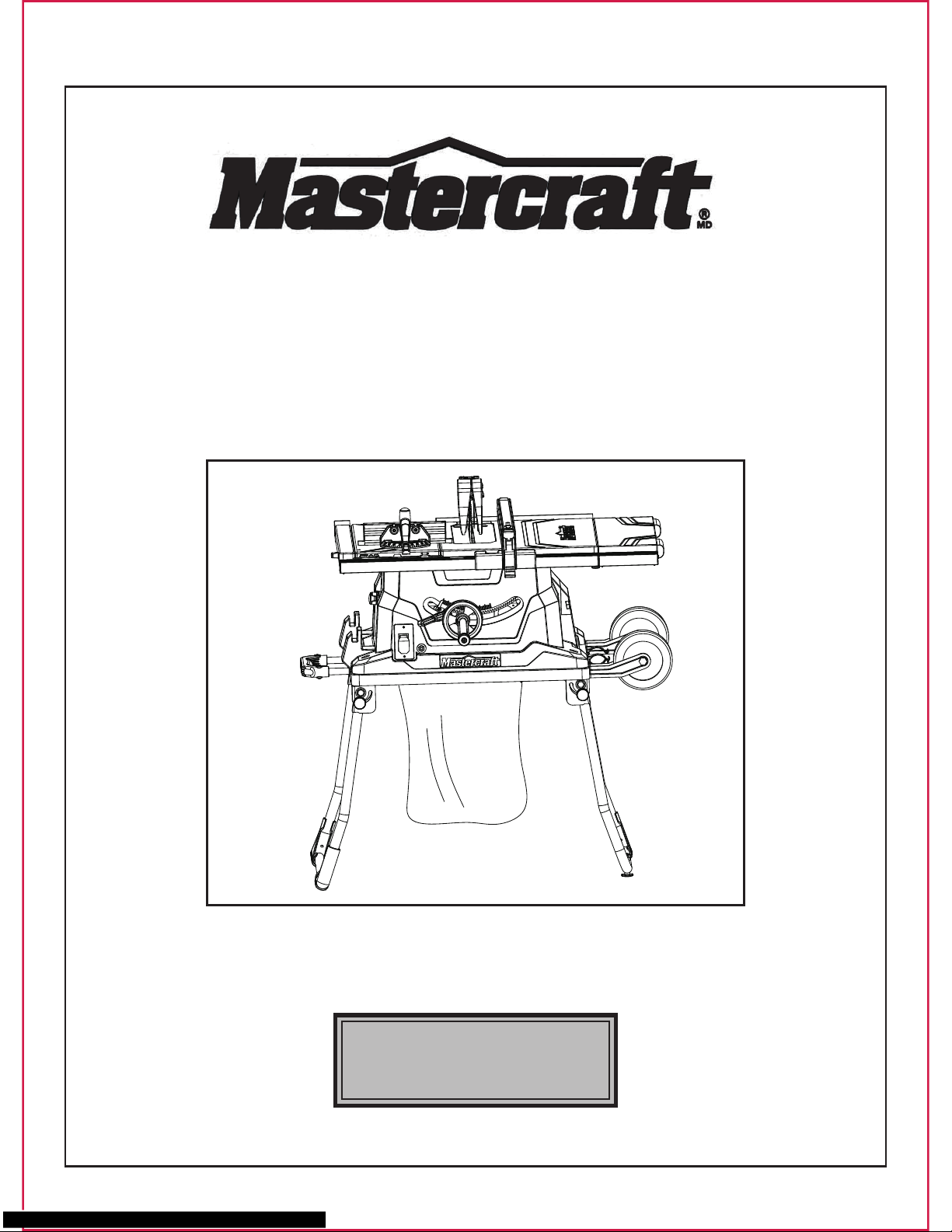
TABLE SAW
WITH SLIDING TABLE
055-6742-8
User Manual
Toll-free helpline
1-800-689-9928
Page 2

2
Table of contents
I.Specifications
SECTION
PAGE
I. Specifications
II. General safety guidelines
III. Electrical information
IV. Know your table saw
V. Assembly and adjustments
VI. Operating instructions
VII. Maintenance
VIII. Troubleshooting guide
IX. Warranty
X. Part list
Motor: 120 V, 60 Hz, 15 A,
Speed: 4500 RPM (no load)
Blade: 10” (25.4 cm) carbide-tipped
Right extension table: 19 11/16 x 6 1/10” (50 x 15.5 cm)
Main table size: 26 1/2 x 19 11/16” (67.3 x 50 cm)
Rear table size: 26 1/2 x 2 1/2” (67.3 x 6.4 cm)
Sliding tale size: 8 2/3” x 19 11/16” (22 x 50 cm)
Laser: Class IIIA
Laser wavelength: 630–665 nm
Laser outpower: <5 mW
Net weight: 75 lb (34 kg)
Depth of cut at 90°: 3 9/64” (8 cm)
Depth of cut at 45°: 2 5/32” (5.5 cm)
2
3
7
8
9
23
30
32
33
34
............................................................................................
........................................................................
..............................................................................
...............................................................................
......................................................................
............................................................................
..........................................................................................
..........................................................................
.................................................................................................
....................................................................................................
Page 3
1. 1. Store all safety guidelines and instructions for future use.
2. This device is not intended for use by people (including children) lacking experience with
electrical power tools unless they have received instructions about how the device is to be
used. Children have to be supervised to ensure that they do not play with the device.
3. Store the operating instructions so that they are always available to the user of the tool
when it is being operated.
4. If you lend this device to other people, then always hand over these operating instructions to
ensure safe use. Instruct inexperienced people in accordance with these safety instructions.
5. Keep your working area tidy. Untidiness in your work area can cause accidents.
6. Pay attention to the surrounding conditions. Do not expose the electric power tool to rain. Do
not use electric power tools in damp or wet conditions. Ensure that the work area is well lit.
Do not use electric power tools where there is a danger of fire or explosion.
7. Protect yourself against electric shocks. Avoid bodily contact with earthed parts (e.g. pipes,
radiators, electric hobs or cooling appliances).
8. Keep other people away from the work area. Do not let other people, especially children,
touch the electric power tool or the power cable. Keep them away from your work area.
9. Store unused electric power tools safety. Unused electric power tools should be stored in a
dry, high-lying or locked place, out of the reach of children.
10.Do not overload your electric power tool. It works better and more securely within the stated
output range.
11.Use the correct electric power tool. Do not use inefficient machines for heavy work. Do not
use the electric power tool for purposes which it was not intended for. For example, do not
use circular saws to cut wooden masts or logs.
12.Wear suitable clothing. Do not wear baggy clothing or jewellery, as they can be caught by
moving parts. When working outdoors, anti-slip shoes are recommended. If you have long
WARNING: Read all the safety guidelines and instructions before you use this electric power
tool!
3
WARNING! When using electrical power tools, the following essential safety measures have
to be observed to prevent electric shocks, injury and fire hazards. Failure to adhere to the
safety guidelines and instructions can cause electric shock, fire and/or severe injuries.
II. General safety guidelines
Page 4

hair, wear a hair net.
13.Wear safety equipment. Wear safety goggles. If the work creates dust, wear a dust mask.
14.Attach the dust extraction unit. If there are connections for dust extraction and collection
equipment, then make sure that the equipment is correctly attached and used.
15.Never use the cable for purposes which it is not intended for. Do not use the cable to pull the
plug out of the power socket. Protect the cable form heat, oil and sharp edges.
16.Secure the workpiece, when necessary use clamping devices to secure the workpiece.
The workpiece is thereby secured better than by hand.
17.Avoid taking abnormal stances. Make sure you stand securely and keep your balance at all
times.
18.Look after your tool with care. Keep the cutting tool sharp and clean so that you are able to
work better and safer with it. Observe the guidelines on lubrication and exchanging the tool.
Check the power cable of the electric power tool regularly and in case of damage let a
recognized specialist repair it. Check extension cables regularly and replace them if they are
damaged. Keep the handles dry, clean and free of oil and grease.
19.Pull the plug out of the power socket when the electric power tool is not in use, before
maintenance and when exchanging tools such as saw blades, drills and mills.
20.Do not leave keys in the device. Before you switch the device off, check that keys and setting
tools have been removed.
21.Avoid starting-up the device accidentally. Make sure that when you insert the plug into the
power socket, the power switch is turned off.
22.Use an extension cable when working outdoors. Only use extension cables outdoors which
are authorized for outdoor use and are correspondingly marked.
23.Be attentive. Be careful what you do. Carry out your work sensibly.
24.Check the electric power tool for any sign of damage. Before continuing work with electric
power tool, safety devices or easily damaged parts have to be carefully checked to ensure
that they function properly and are not defective. Check that the moving parts are working
properly and are not jammed, or whether the parts are damaged. All parts must be correctly
assembled by an experienced individual, unless stated otherwise in the operating instructions,
and meet all required conditions in order to guarantee that the electric power tool functions
without a problem. Damaged switches have to be replaced by a qualified electrician. Do not
use electric power tools if the power switch cannot be turned on and off.
II. General safety guidelines(continued)
4
Page 5
Additional safety guidelines for circular table saws
5
II. General safety guidelines(continued)
25.WARNING!The use of other insertion tools and accessories can present a danger of injury to
you.
26.Let a specialist electrician repair your electric power tool. This electric power tool corresponds
to the applicable safety conditions. Repairs are only allowed to be carried out by a specialist
electrician, using original replacement parts; otherwise accidents may occur.
27.No other people are allowed to stand in the direct vicinity of the machine when it is in use.
People not operating the machine must maintain a suitable safe distance!
28.Never lay the power cable over the machine table!
29.Use the push rod to pass the workpiece safely into the saw blade! Do not come too close to
the saw blade!
30.Make sure that the thickness of the material to be cut is less than the maximum possible
cutting depth.
31.Never cut “hands-free”! The workpiece must always lie level on the machine table and be
moved along the stop! The workpiece must always be pressed hard against the stop!
32.Never cut workpieces that are so small that they cannot be safety pressed against the stop
and could turn!
33.Never cut workpieces that are so small that they cannot be moved by the push rod at a safe
distance from the saw blade!
34.Only cut one workpiece at a time! Never cut several workpieces simultaneously! Workpiece
are not allowed to be placed behind or on top of each other!
35.There is a danger of the workpiece “jamming” and slipping away!
36.Make sure that the workpiece cannot slip while cutting or get jammed in the saw blade!
37.Clean the working area and the workpiece after each cut.
Warning! Switch the device off, remove the plug from the power socket and let the machine
come to a standstill! No foreign bodies are allowed to be on the workpiece or the machine
table! Cut pieces of the workpiece can be caught by the rotating cutting disc and be flung
away!
Page 6

KEEP THIS USER’S MANUAL IN A SAFE PLACE FOR FUTURE REFERENCE.
6
II. General safety guidelines(continued)
38.Never reach into the openings of the device! Never insert objects into the openings of the
device (e.g. the saw blade casing, dust extraction adaptor). Danger of cuts!
39.Never remove the cutting piece if the machine is still switched on or running! Danger of cutting
yourself!
40.Cut workpieces may have sharp edges, ridges or wooden splinters! Danger of cutting injuries!
41.Always switch the machine off and remove the power plug when your leave the machine.
42.Never expose the device to rain or extreme moisture!
43.Do not perform any cuts with this circular table saw, other than those described in these
operating instructions! Seams and notches are not allowed to be sawn!
44.Circular saws are not allowed to be used for slitting (notches which end in the workpiece)!
Page 7
III. Electrical information
7
Make sure your extension cord is properly wired and in good condition. Always replace a
damaged extension cord, or have it repaired by a qualified person before using it. Protect your
extension cords from sharp objects, excessive heat, and damp or wet areas.
Use a separate electrical circuit for your tools. This circuit must consist of not less than #12 wire
with a 20 A time-delayed fuse or a #14 wire with a 15 A time-delayed fuse. Before connecting the
motor to the power line, make sure the switch is in the OFF position and the electric current is
rated the same as the current stamped on the motor nameplate. Running at a lower voltage will
damage the motor.
GUIDELINES FOR USING EXTENSION CORDS
WARNING: THIS TABLE SAW IS INTENDED FOR INDOOR USE ONLY. DO NOT EXPOSE
IT TO RAIN OR USE IT IN DAMP LOCATIONS.
Make sure the extension cord is in good condition. When using an extension cord, be sure to use
one that is heavy enough to carry the current that your product will draw. An undersized cord will
cause a drop in line voltage, which will result in loss of power and overheating. The table below
shows the correct size to be used according to cord length and nameplate ampere rating. When
in doubt, use the next heavier gauge. The smaller the gauge number, the heavier the cord.
MINIMUM GAUGE FOR EXTENSION CORDS(AWG)
(when using 120 V only)
Ampere Rating Total length of cord in feet (metres)
More Than Not More Than
0
6
10
12
6
10
12
16
25’ (7.6 m)
18
18
16
14
50’ (15.2 m)
16
16
16
12
100’ (30.5 m)
16
14
14
150’ (45.7 m)
14
12
12
Not Recommended
WARNING: THIS TOOL MUST BE GROUNDED WHILE IN USE IN ORDER TO PROTECT
THE OPERATOR FROM ELECTRIC SHOCK.
Page 8
8
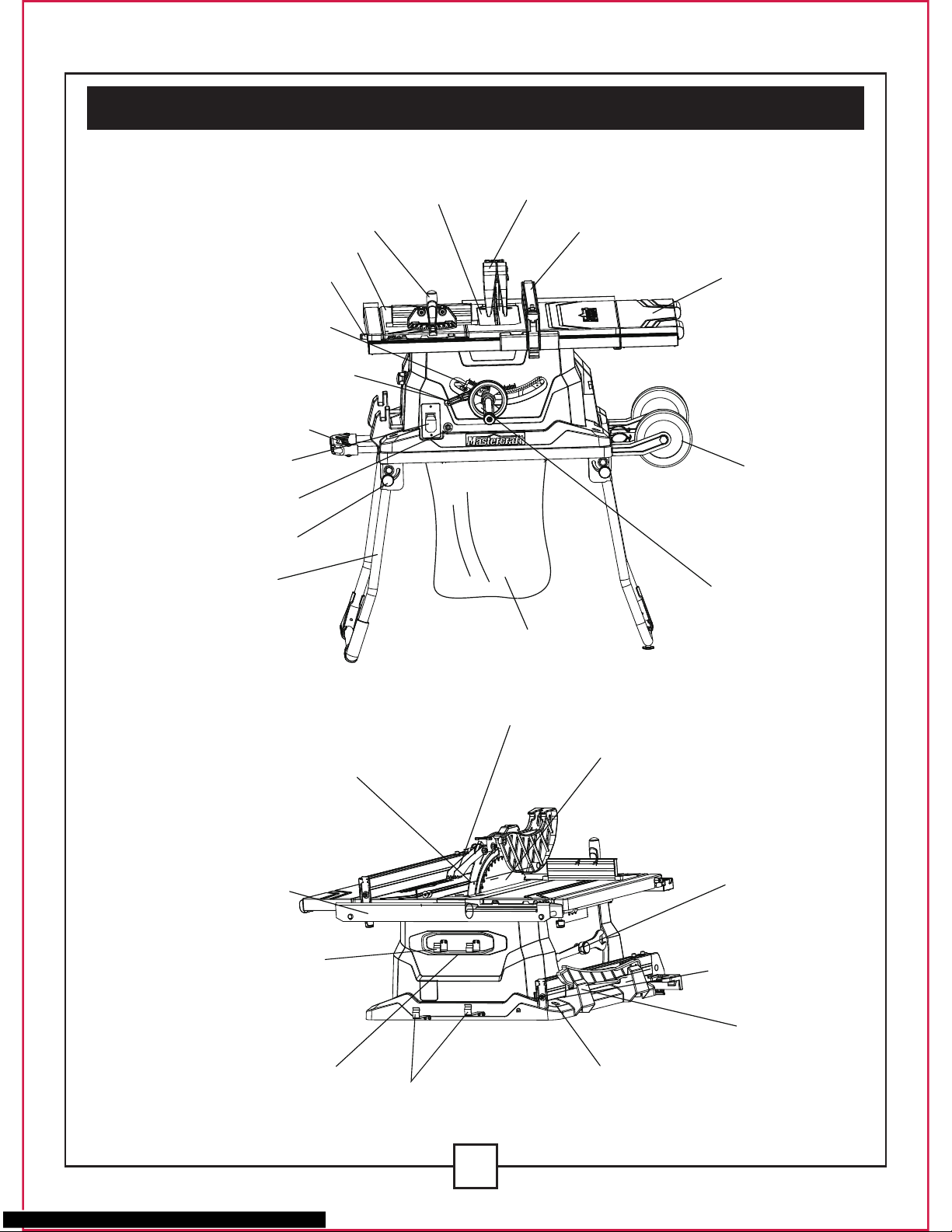
IV. Know your table saw
Mitre gauge
ON/OFF switch Key
Bevel angle
pointer and scale
Roller wheels
Rip fence
Blade guard
Table insert
Sliding mitre table
Sliding mitre table
locking lever
Fold and roll stand
Blade raising/tilting
control handle
Bevel angle
pointer and scale
Blade bevel
lock knob
Stand handle
Stand leg locking
lever
Dust bag
Side table
extension
Mounting
hole
Blade
Anti-Kickback pawls
Splitter
Rear
extension
table
Cord wrap
Limited hook
Guard pothook
Push
sticker
storage
Blade
storage
Rip fence
storage
Page 9
9
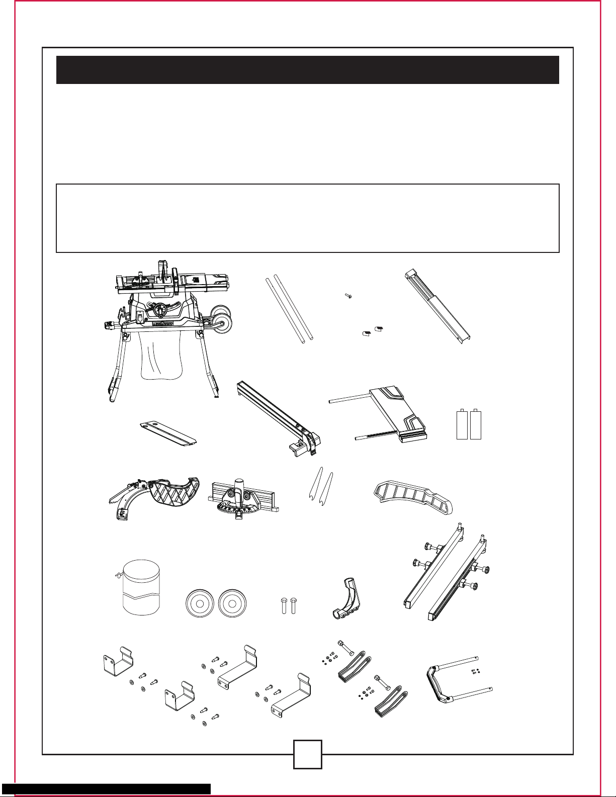
V. Assembly and adjustments
UNPACKING
1. Carefully remove the table saw from the carton.
2. Separate the parts.
3. Lay out all of the parts, and check them against the parts listed below. Examine all of the
parts carefully.
WARNING:
• IF ANY PART IS MISSING OR DAMAGED, DO NOT PLUG THE TABLE SAW IN UNTIL
THE MISSING OR DAMAGED PART HAS BEEN REPAIRED OR REPLACED.
• FOR MORE INFORMATION, CALL THE TOLL-FREE HELPLINE AT 1-800-689-9928.
Batteries
Table saw assembly
Dado insert
Blade guard
and splitter
Mitre gauge Blade wrenches
Dust bag
Limited hook Guard pothhook Wheel support Pull handle
Roller wheels Hex bolts Levelling pad Stand extension poles
Push sticker
Rip fence Right table extension
Rear table extension
tubes
Locating seats
Rear table
extension
Screw
Page 10
10
WARNING: The laser beam is emitted when the laser line is turned on. Do not stare into the
beam or view it directly using optical instruments. Do not remove the warning label that is
aaffixed to the laser cover. Avoid aiming the laser beam directly into the eyes. Caution-use of
controls or adjustments or performance of procedures other than those specified herein may
result in hazardous radiation exposure.
CAUTION-The use of optical instruments with this product will increase eye hazard.
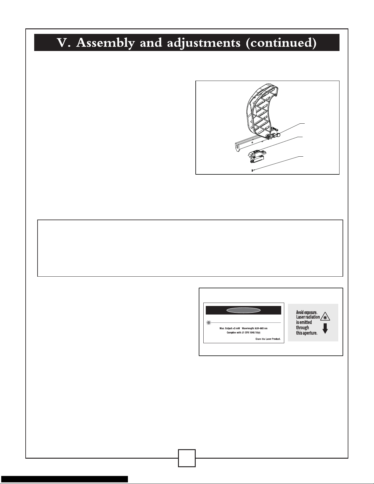
INSTALLING THE BATTERIES FOR THE LASER LINE (FIG. 1)
THE LASER LINE
1. Uninstall the blade guard component by
loosening the handle (1). Remove the
locking screw(2) on the battery box cover
with a screwdriver, and open the battery
compartment.
2. Install two “AAA” batteries.
3. Install the battery box cover by closing the
screw (2), tighten it securely.
4. Turn the switch (3) to the ON position in
order to activate the laser cutting guide.
This tool is equipped with a Hawkeye Laser Line, which is a battery-powered laser cutting guide.
The laser line allows the operator to anticipate the path of the saw blade on the workpiece before
beginning cutting.
Fig. 1
1
3
2
NOTE
• A laser beam is not a toy, and it should not be
used by children. Misuse of the laser line can lead
to irreparable eye damage.
• strongly recommend the use of laser protective
eyewear for the specific wavelength of emitted
light when working on or near reflective surfaces.
• Do not perform any adjustments that are intended
to increase the power of the laser.
• When using the laser line, do not point the laser beam at people and/or reflecting surfaces. Even
a low-intensity laser beam can cause eye damage. Do not look directly into the laser beam.
• If the laser line will not be used for more than three months, remove the batteries in order to
avoid damage from possible leakage.
• The laser line does not include any user-serviceable components. Do not open the housing in
an attempt to repair it.
• Repairs should only be carried out at a service centre or by an authorized service technician.
DANGER
LASER RADIATION-AVOID DIRECT EYE EXPOSURE
Page 11
2
1
Fig. 3
11
Keep Work Areas Clean
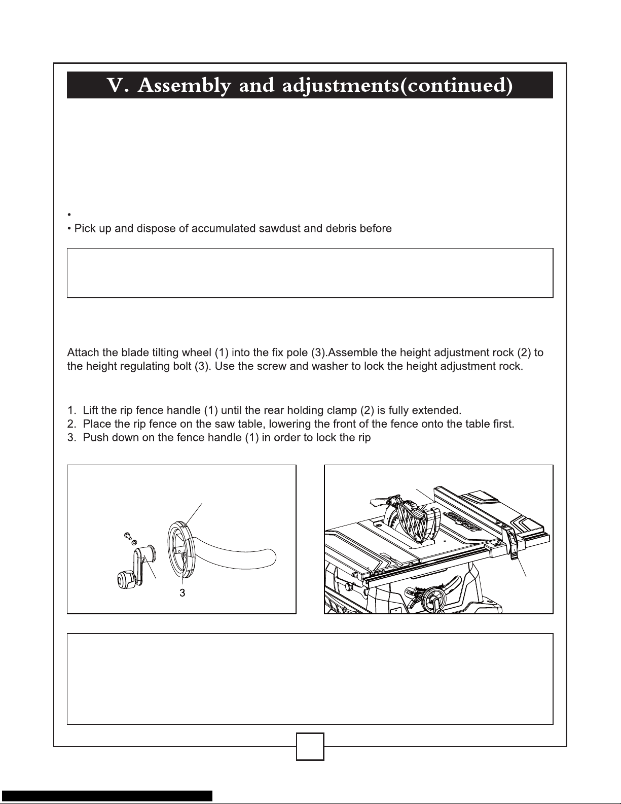
ASSEMBLING THE BLADE RAISING/
TILTING CONTROL HANDLE (FIG. 2)
RIP FENCE (FIG. 3)
WARNING: KEEP THE WORK AREA CLEAN, UNCLUTTERED, AND WELL-LIT. DO NOT
WORK ON A FLOOR SURFACE THAT IS SLIPPERY FROM ACCUMULATED SAWDUST,
DEBRIS OR WAX.
WARNING: IN ORDER TO AVOID INJURY FROM AN ACCIDENTAL START-UP, VERIFY
THAT THE POWER SWITCH IS IN THE “OFF” POSITION, THAT THE SAFETY KEY IS
REMOVED, AND THAT THE POWER CORD IS NOT PLUGGED INTO THE OUTLET. IN
ORDER TO AVOID SERIOUS INJURY, THE REAR OF THE TABLE INSERT MUST BE
FLUSH WITH THE TABLE DURING ALL SAWING OPERATIONS. A RUBBER ADJUSTING
SPACER IS PROVIDED UNDER THE REAR OF THE INSERT FOR THIS PURPOSE.
Accumulated sawdust and wood chips can pose a safety hazard.
each cutting operation.
fence in position.
Fig. 2
1
2
CAUTION
LASER RADIATION.
Do not stare into the beam or view it directly using optical instruments.
Maximum output: <5 mW Wavelength: 630-665 nm Protection Class: IIIA
Page 12
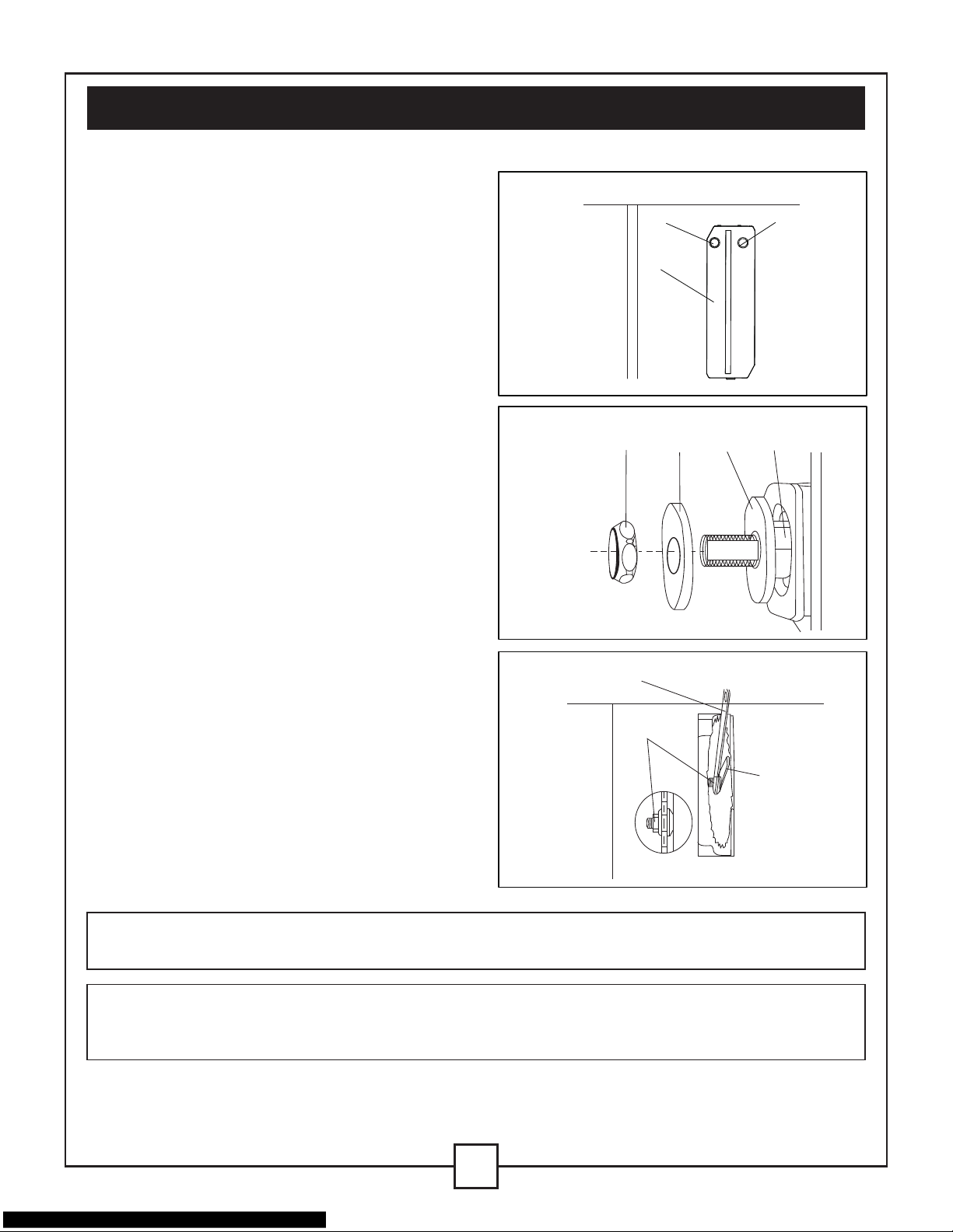
Fig. 4
2
1
3
V. Assembly and adjustments(continued)
12
WARNING: VERIFY THAT THE SAW BLADE, THE ARBOR FLANGE, AND THE NUT ARE
PROPERLY SEATED, AND THAT THE ARBOR NUT IS TIGHTENED SECURELY.
WARNING: IN ORDER TO AVOID INJURY FROM AN ACCIDENTAL START-UP, VERIFY
THAT THE POWER SWITCH IS IN THE “OFF” POSITION, AND THAT THE POWER CORD
IS NOT PLUGGED INTO THE OUTLET.
INSTALLING THE BLADE TO THE
ARBOR (FIG. 4, 5, 6)
1. Remove the table insert(1)by inserting the
finger into the hole (2&3) (see Fig.4).
2. Raise the saw blade arbor (4) to its maximum
height by turning the blade raising control
handle counter-clockwise. Remove the arbor
nut (5) and the outer flange (6) from the saw
arbor.
3. Place the saw blade onto the arbor, with the
teeth of the blade pointing DOWN toward
the front of the saw.
4. Place the flange (6) and the arbor nut (5)
onto the arbor, and hand-tighten the nut.
Verify that the saw blade is firmly seated
against the inner flange (7) (Fig. 5).
NOTE: Verify that the large, flat surfaces
of the flange and the nut face INWARD,
toward the saw blade.
5. Place the open-ended blade wrench (8) on
the flat of the outer flange (6) in order to prevent
the arbor from turning while tightening.
Tighten the arbor nut by turning it clockwise
using the box-end blade wrench (9) (Fig. 6).
Fig. 5
Fig. 6
8
5
9
4
7
6
5
Page 13

WARNING:Improper alignment of the splitter can cause “kickback” and serious injury.
ASSEMBLING THE BLADE GUARD
(Fig. 7, 8 & 9)
V. Assembly and adjustments(continued)
13
VERIFY THAT THE SAW IS
DISCONNECTED FROM THE OUTLET
BEFORE INSTALLING THE BLADE
GUARD AND SPLITTER ASSEMBLY.
1. Use the handwheel to set the blade to
the maximum height and to set the tilt
to 0° on the bevel scale. Lock the
blade bevel locking knob.
3. Insert the blade guard assembly (1)
into the splitter bracket, as shown.
(Fig. 8)
4. Using a straight edge (2), verify
whether the blade guard splitter (3)
is aligned with the saw blade (4),
with the straight edge lying between
the teeth of the blade. (Fig. 9)
NOTE: The blade guard and splitter
must always be correctly aligned so
that the cut workpiece will pass on
either side of the splitter without
binding or twisting to the side.
Fig. 7
Fig. 8
Fig. 9
1
2
4
3
2. After loosing the knob (6),press the
device(5),the splitter (7) should be at
the highest position(Fig.7)
5
6
7
Page 14

ASSEMBLING THE TABLE
EXTENSION WING (FIG. 10, 11)
NOTE:
ADJUSTING THE TABLE EXTENSION
WING (FIG. 11)
WARNING:In order to avoid injury from an accidental start-up, verify that the power switch is
in the “OFF” position, and that the power cord is not plugged into the outlet.
A. Install the extension component (1) (2) into
the two holes at the side of the main table.
(Fig. 10)
B. Install the locking knobs (3) on the
aluminum extension wing. (Fig. 11)
INSTALLING THE MITRE GAUGE
(FIG. 12)
1. Position the mitre body (2) at 90°, and tighten
the handle (3) in order to secure the mitre
body in position.
2. Place the mitre gauge into the slot (4) of the
sliding mitre table (5).
3. Release the locking bolt (1) before using
the sliding mitre table.
Follow these steps to adjust the position of the
extension table
1. Unlock the locking knobs (3) on the two
extension tube brackets.
2. Slide the extension tubes in or out, until the
scale on the front tube is positioned at the
desired distance. Lock the locking knobs (3)
V. Assembly and adjustments(continued)
14
Fig. 10
Fig. 11
Fig. 12
1
2
2
3
1
5
4
2
1
3
Page 15

2
1
4
3
ADJUSTING THE MITRE GAUGE
(FIG. 13)
INSTALLING THE REAR TABLE
EXTENSION (FIG. 14)
ADJUSTING THE REAR TABLE EXTENSION
1. Loosen the locking handle (1) in order to
allow the mitre body (2) to rotate freely
(Fig. 13). Position the mitre body at 90°
so that the positive detent secures it in
position. Tighten the locking handle in order
to hold the mitre body securely in position.
2. If the pointer (3) requires adjustment, loosen
the screw that is located under the pointer
using a screwdriver.Adjust the pointer to 90°
on the scale, and then tighten the adjusting screw firmly.
3. In order to change the angle of the mitre gauge, loosen the locking handle (1) and the rotate
the mitre body to the desired angle, as indicated on the scale. Tighten the locking handle in
order to hold the mitre body securely in position.
1. Place the rear table extension onto the two
rear table extension tubes (1).
2. Snap the two locating seats (2) over the two
rear table extension tubes (1). Verify that the
locating pin in the locating seat fits into the
corresponding hole in the extension tube.
3. Insert the rear table extension tubes (1) into
the two holes in the rear of the saw table, and
into the extension tube brackets that are
located under the table. Position the rear table support so that the instruction labels are facing
up.
4. Tighten one extension wing stop screw (4) on the end of the left rear table extension tubes (1).
Verify that the screw is fully inserted into the corresponding hole (3) in the extension tube.
1. When ripping a short workpiece, the rear extension table should be positioned as close to the
rear of the main table as possible.
2. When ripping a long workpiece that requires extra support as the cut is completed, the rear
extension table should be pulled out as far as possible, until the locating seat prevents it from
moving out any further.
V. Assembly and adjustments(continued)
15
Fig. 13
Fig. 14
30
45
60
75
75
90
60
45
30
2
1
3
90°
Page 16

ADJUSTING THE RIP FENCE (FIG. 15)
1. Move the rip fence (1) by releasing the
handle (2) and sliding the fence to the
desired location. Push the handle down in
order to lock the fence into position.
2. Position the fence on the right side of the
table, and along the edge of the mitre gauge
groove.
3. Lock the fence handle. The fence should be
parallel to the mitre gauge groove.
4. If adjustment is required in order to make the
fence parallel to the groove, follow these
steps:
•Loosen the two bolts (3), and release the
handle (2).
•Hold the fence bracket (4) firmly on the front of the working table. Move the fence until it is
parallel to the mitre gauge groove.
•Push the handle down, and tighten both screws.
5. If the fence is loose when the handle is in the locked (down) position, follow these steps:
•Release the handle (2) and turn the adjusting nut (5) clockwise until the fence can be locked
on the table.
•Do not over-tighten the adjusting screw. Otherwise it will cause the fence to come out of the
table.
ADJUSTING THE RIP FENCE INDICATOR (FIG. 15)
1. The rip fence indicator (6) points to the measurement scale. The scale shows the distance
from the side of the fence to near side of the blade.
2. Measure the actual distance using a ruler. If there is a difference between the measurement
and the indicator, adjust the indicator (6).
3. Loosen the screw (7), and slide the indicator to the correct measurement on the scale.
Tighten the screw, and re-measure using the ruler.
RAPID BLADE TILTING (FIG. 16)
1. Loosen the blade bevel locking knob (2).
2. Slide the entire control handle assembly (3) to
the desired location.
3. Tighten the blade bevel locking knob (2).
Verify that the locking knob is tightened
securely before attempting a cut.
NOTE: The angle of the blade can be changed
without changing the height of the blade,
V. Assembly and adjustments(continued)
16
Fig. 15
5
1
3
4
2
6
7
Fig. 16
1
2
3
Page 17

WARNING: THE BLADE BEVEL LOCKING KNOB (2) MUST BE TIGHTENED SECURELY
AND LOCKED DURING ALL CUTTING OPERATIONS..
Turn the control handle (1) CLOCKWISE in order to raise the saw blade. Turn the control handle
(1) COUNTER-CLOCKWISE in order to lower the saw blade.
NOTE: It is not necessary to loosen the blade bevel locking knob (2) in order to raise or lower the
saw blade.
1. Raise the blade to the maximum height by
turning the control handle counter- clockwise.
2. Loosen the bevel angle locking knob.
3. Tilt the blade to the 90°(0°) bevel.
4. Using a square (1), verify that the blade is at a
90° (0°) angle to the table top.
5. If blade is not at a 90° (0°) angle to the table,
back off the adjustment screw (2).
6. Loosen the bevel locking knob and square the
blade 90° (0°) to the table.
7. Once the blade is at a 90° (0°) angle to the
table top, tighten the bevel angle locking knob.
8. Carefully tighten the adjusting screw (2) until
it touches the bevel stop. DO NOT OVERTIGHTEN.
9. Verify that the blade is still aligned at 90° (0°).
Once the blade has been set at a 90° (0°) angle
to the table top, as described in section above,
the angle pointer (1) may require adjustment.
If it does, follow these steps:
1. Loosen the pointer screw (2), and move the
pointer until it is aligned with 90° (0°) on the
bevel scale.
2. Retighten the pointer screw.
1. Raise the blade to the maximum height by
turning the control handle counter- clockwise.
2. Loosen the bevel angle locking knob.
3. Tilt the blade to the 45° bevel.
4. Using a square (1), verify that the blade is at
a 45° angle to the table top.
V. Assembly and adjustments(continued)
17
ADJUSTING THE BLADE HEIGHT
(FIG. 16)
90°(0°) BEVEL STOP (FIG. 17)
BEVEL POINTER ADJUSTMENT
(FIG. 18)
45° BEVEL STOP (FIG. 19)
Fig. 17
Fig. 19
Fig. 18
1
2
1
2
2
1
Page 18

ADJUSTING THE LASER GUIDE (FIG. 20)
WARNING: The laser beam is emitted when the laser guide is turned on. Do not stare into
beam or look directly at it using optical instruments. Do not remove the warning label that is
affixed to the blade guard. Do not direct the laser into the eyes.
strongly recommend the use of laser protective eyewear for the specific wavelength of
emitted light when working on or near reflective surfaces.
WARNING:DO NOT PLUG THE TABLE SAW INTO THE OUTLET UNTIL ALL
INSTALLATIONS AND ADJUSTMENTS HAVE BEEN COMPLETED AND THE SAFETY AND
OPERATIONAL INSTRUCTIONS IN THIS MANUAL HAVE BEEN READ CAREFULLY AND
UNDERSTOOD FULLY.
5. If blade is not at a 45° angle to the table, back off the adjustment screw (2).
6. Loosen the bevel locking knob and set the blade at a 45° angle to the table.
7. Once the blade is at a 45° angle to the table top, tighten the bevel angle locking knob
8. Carefully tighten the adjusting screw (2) until it touches the bevel stop. DO NOT
OVERTIGHTEN.
9. Verify that the blade is still aligned at 45°.
NOTE: All of the adjustments for the operation of
this machine have been carried out at the factory.
Occasional readjustments may be necessary as
a result of normal wear and use.
1. Turn the laser guide on. Place a straight edge
or ruler against the right side of the blade.
2. Verify whether the laser line is flush against
the right side of the blade, and against the
straight edge or ruler.
3. If the laser line is not flush, loosen the two
set screws (2) with a hex wrench, but do
not remove them.
4. Using a hex wrench (not provided), adjust the laser unit (1) until the laser line is
parallel with the blade.
NOTE: Be careful not to over-rotate the laser unit. Do not rotate the laser more than 1/8 of a turn
in either direction.
5. Adjust the set screw (2) on the left or right side in order to shift the laser line until it is flush
with the right side of the blade. Once proper alignment has been achieved, tighten the set
screw on the other side slowly, until it touches the laser, in order to lock the laser into position.
Turn the laser guide off.
V. Assembly and adjustments(continued)
18
Fig. 20
1
2
Page 19

ASSEMBLING THE
ROLLER WHEELS (FIG. 21)
Attach the roller wheels (7) to the
roller wheel supports (12) using hex
bolts (8) and nuts (9), as
illustrated. Do not over tighten,
because doing so will not allow
the wheels to turn.
Leveling pad (5) the is installed at
the four corners of stand by hex bolt.
stand extension poles (10) is
installed at the lateral of stand.
align two tips of pull handle (11) to
the holes in the stand bracket and
tighten them.
ATTACHING THE TABLE SAW TO THE
STAND (FIG. 22)
1. Place the stand on a level surface, and adjust
the right front adjustable stand pad (1) in
order to level the stand to the floor.
2. Place the table saw on top of the stand (1),
aligning the holes in the base with the holes
in the stand.
3. Insert four hex bolts (2) through flat washers
and through the holes in the base and the
stand.
4. Tighten all four bolts. NOTE: Do not over
tighten the bolts that hold the saw to the
stand. Doing so may damage the saw base.
V. Assembly and adjustments(continued)
19
UNFOLDING THE STAND (FIG. 21)
Fig. 21
Fig. 22
1. Release the knob (1)(2).
2. Lift the stand up, unfold the wider leg set (3)and unfold the narrower leg set (4).
3. Lock the locking knobs (1)(2).
NOTE: Verify that the stand is securely locked in position.
4. Attach the levelling pad (5) to the wider leg set (3) using the screw (6).
1
2
7
8
12
9
5
6
4
1
3
2
11
10
Page 20

V. Assembly and adjustments(continued)
20
NOTE:
Verify that the table saw is securely locked in position, and that the adjustable stand pad has
stabilized the table saw before operation.
FOLDING THE TABLE SAW/STAND (FIG. 23)
SETTING UP THE TABLE SAW/STAND (FIG. 23)
1. Rotate the stand locking hook to the left. Lift up the two right-side stand locking levers in
order to unlock, and lift the right side of the table saw up slightly off the floor (Fig. 23). Fold
the leg set on the right side up to the base of the saw until it snaps into position with the
spring clip (Fig. 23).
2. Slide the table extension toward the table until it rests against the saw table (Fig. 23-1).
3. Rest the right side of the saw onto the floor, release the two left-side stand locking levers,
and tilt the saw on its right side. Fold the left-side leg set up to the base (Fig. 23).
4. Secure the legs into position by rotating the stand locking hook to the right.
1. Rotate the stand locking lever to the left. Unfold the leg set, and lock the stand locking levers
in position by sliding the levers down the slots of the mounting brackets and pushing down in
order to lock it in position.
2. Rest the left side of the saw on the floor, lift up the right side of the stand, and unfold the
narrower right-side leg set (Fig. 23).
3. Secure the right-side legs in position by locking the stand locking levers in position, as
described in step 1
WARNING:Do not use this saw to cut metal. The hot chips or sparks may ignite sawdust or
the material of the bag.
Fig. 23 Fig. 23-1
FOLDING
SET-UP
1
1 2 3
2
Page 21

WARNING:FAILURE TO PROVIDE THE SAWDUST FALL-THROUGH AND REMOVAL
HOLE WILL CAUSE SAWDUST TO BUILD UP IN THE MOTOR AREA, WHICH MAY
RESULT IN A FIRE HAZARD OR CAUSE DAMAGE TO THE MOTOR.
proceed to step 5. If there is a hole that is large enough, proceed to step 7.
5. Mark a 11x11” (28x28 cm) square (2), centred between the four mounting holes (1).
6. Cut out and remove the square. This opening will allow sawdust to fall through the saw base.
7. Place the table saw on the workbench tabletop, and align the holes of the table saw with the
holes that were drilled in the workbench tabletop. Fasten the table saw to the workbench
using bolts and nuts.
IMPORTANT: When mounting the saw to the stand or workbench DO NOT over tighten the
mounting bolts.
NOTE: If the stand or the workbench tends to move while the table saw is in use, the stand or
workbench must be fastened to the floor.
V. Assembly and adjustments(continued)
21
INSTALLING THE DUST BAG (FIG. 24)
1. Place the dust bag around the neck of the
dust port. Tie the dust bag by pulling the
drawstring tight, and secure it using the
tie-clip.
MOUNTING THE TABLE SAW TO A
WORKBENCH (FIG. 24-1)
1. If the stand will not be used, the table saw
must be properly secured to a sturdy
workbench using the four mounting holes
on the base.
2. The workbench must have a hole that is
large enough to allow for sawdust fall through and removal.
3. Place the table saw in the centre of the
workbench tabletop, and mark the location
of the four 3/8” (9.5 mm) mounting holes
(1) on the workbench tabletop.
4. Drill four 3/8” (9.5 mm) holes in the
workbench tabletop.
NOTE: If there is not a hole that is large
enough for sawdust removal and fall through,
Fig. 24
Fig. 24-1
SQUARE
CUTOUT
1
2
Page 22

V. Assembly and adjustments(continued)
22
LIMITED HOOKS AND GUARD PATHHOOKS (Fig. A)
1. Align the holes in the limited hooks (1)and the body of table saw.
2. insert head srew through flat washer and the holes in limtted hooks.
3. Tighten the screws with cross screwdriver.
4. About guard pathhooks(2),pls follow the same assemble procedure of limited hooks.
Fig. A
1
2
Page 23

OVERLOAD PROTECTION (FIG. 24-3)
WARNING:IN ORDER TO AVOID INJURY AND PREVENT ACCIDENTAL START-UP WHEN
THE RESET BUTTON IS PUSHED, THE ON/OFF PADDLE SWITCH SHOULD BE IN THE
OFF POSITION, AND THE POWER CORD SHOULD BE UNPLUGGED FROM THE
OUTLET WHILE THE SAW IS COOLING DOWN. OVERHEATING MAY BE CAUSED BY AN
UNDER-SIZED EXTENSION CORD, AN EXTENSION CORD THAT IS TOO LONG,
MISALIGNED PARTS, OR A DULL BLADE. INSPECT THE SAW FOR PROPER SET-UP
BEFORE USING IT AGAIN.
This saw is equipped with a reset overload relay button (1) that will restart the motor after it shuts
off due to overloading or low voltage. If the motor stops during operation, move the ON/OFF
switch to the OFF position. Wait approximately five minutes for the motor to cool down, and then
push the reset button (1) and move the switch to the ON position.
23
RAISING THE BLADE (FIG. 24-2)
TILTING THE BLADE (FIG. 24-2)
ON/OFF PADDLE SWITCH (FIG. 24-3)
1. Loosen the blade bevel locking knob (2).
2. Slide the entire control handle assembly (1) to
the desired location.
3. Tighten the blade bevel locking knob (2). Verify
that the locking knob is fully tightened before
attempting a cut.
The ON/OFF paddle switch has a removable
safety key. The saw cannot be turned on when
the key is removed from the switch, which
minimizes unauthorized use.
1. To turn the saw ON, insert the safety key (2)
into the slot that is located above the switch,
and then move the paddle switch (3) up to the
ON position.
2. To turn the saw OFF, move the paddle switch
(3) down. (Fig. 24-3)
3. To lock the saw in the OFF position, grasp the
end of the safety key and pull it out.
4. The ON/OFF switch will not operate with the
safety key removed.
5. If the safety key is removed while the saw is running, the saw can be turned OFF, but it cannot
be restarted until the safety key (2) is reinserted.
Turn the blade raising control handle (1) COUNTER-CLOCKWISE in order to raise the blade.
NOTE: It is not necessary to loosen the blade tilting locking knob (2) when raising or lowering the
saw blade.
Fig. 24-2
Fig. 24-3
1
3
2
1
2
Page 24

WARNING:Do not use more than one rip fence or a combination of a mitre gauge and a rip
fence at the same time during a cutting operation.
VI. Operating instructions (continued)
24
WARNING:FOR SAFETY REASONS, VERIFY THAT THE OPERATOR HAS READ THE
SECTION ENTITLED GENERAL SAFETY GUIDELINES FOR THE TABLE SAW BEFORE
OPERATING THIS SAW. VERIFY THE FOLLOWING BEFORE EVERY TIME THE TABLE
SAW IS USED:
1. THE BLADE IS TIGHT.
2. THE BEVEL ANGLE LOCKING HANDLE IS LOCKED.
3. IF RIPPING, THE RIP FENCE LOCKING KNOB IS TIGHT, AND THE FENCE IS
PARALLEL TO THE MITRE GAUGE GROOVE AND THE BLADE.
4. IF CROSSCUTTING, THE MITRE GAUGE KNOB IS TIGHT.
5. THE BLADE GUARD AND SPLITTER ARE IN PLACE, AND ARE WORKING PROPERLY.
6. SAFETY GLASSES ARE WORN.
7. FAILURE TO ADHERE TO THESE SAFETY RULES WILL GREATLY INCREASE THE
CHANCES OF INJURY.
1. Unlock the table extension wing levers (2) on
the two extension tube brackets.
2. Slide the extension tubes in or out until the
scale on the front tube is positioned at the
desired distance. Lock the table extension
wing levers (2).
3. To adjust the position of the fence, loosen the
locking handles (2), and place the auxiliary
fence (1) in position.
4. Tighten the locking handles (2).
Before using the table saw, polish the tabletop with an automotive polishing wax in order to keep
it clean, and to make it easier to slide the workpiece.
There are two basic types of table saw cuts: ripping and crosscutting. Ripping refers to cutting
along the length of the grain and the workpiece. Crosscutting refers to either cutting across the
width or across the grain of the workpiece. This distinction may be hard to make with man made
materials. Therefore, cutting a piece of material to a different width is ripping, and cutting across
the short dimension is crosscutting. Neither operation can be performed safely freehand: ripping
requires the use of the rip fence, and crosscutting requires the use of the mitre gauge. Never use
the rip fence and the mitre gauge at the same time during the cutting operation.
USING THE TABLE EXTENSION WING
(FIG. 25)
Fig. 25
1
2
Page 25

RIPPING (FIG. 26, 26-1)
1. Remove the mitre gauge, and secure the rip fence to the table.
2. Raise the blade until it is approximately 1/8” (3.2 mm) above the top of the workpiece.
3. Place the workpiece flat on the table and against the fence so that the larger portion of the
workpiece is between the blade and the fence. Keep the workpiece approximately 1” (2.5 cm)
away from the blade.
4. Turn the saw ON, and wait for the blade to reach full speed.
5. Slowly feed the workpiece into the blade by pushing forward on the section of the workpiece
that will pass between the blade and the fence (Fig. 26). the pattern that is provided in this
manual. (Fig. 26-1)
VI. Operating instructions (continued)
1
3
2
CAUTION!To prevent serious injury:
• Do not allow frequent use of the table saw to cause complacency and careless mistakes.
Remember that it only takes a fraction of a second of carelessness to cause a severe injury.
• Keep both hands away from the blade and the path of the blade.
• The workpiece must have a straight edge against the fence, and must not be warped,
twisted, or bowed.
6. Do not place your thumbs on the table top. Always hold the workpiece (1) while the blade is
turning. Do not let go of it in order to reach for the push stick. When both thumbs touch the
front edge of the table (2), complete the cut using a push stick (3). Make a push stick using
7. Always use the push stick when performing ripping operations.
8. Continue to push the workpiece with the push stick until it passes the blade guard and clears
the rear of the table.
9. Do not pull the workpiece backward while the blade is turning. Turn the switch OFF, and
unplug the power cord. When the blade comes to a complete stop, raise the anti- kickback
pawls on each side of the splitter, if necessary, and slide the workpiece out.
Fig. 26 Fig. 26-1
1
25
Page 26

VI. Operating instructions (continued)
26
RIPPING SMALL PIECES
BEVEL RIPPING
1. It is not safe to rip small pieces. Instead, rip a larger piece in order to obtain the size of the
desired piece.
2. When ripping a small workpiece, it is not safe to place the hand between the blade and the rip
fence. Use one or more push sticks to push the workpiece completely past the blade.
(Fig. 26-1)
Bevel ripping is the same as ripping, except that the blade bevel angle is set to an angle other
than “0”.
CAUTION!THE WORKPIECE AND THE FENCE MUST BE ON THE RIGHT SIDE OF THE
BLADE WHEN CUTTING.
CAUTION!AVOID INJURY CAUSED BY CONTACT WITH THE BLADE. DO NOT USE THIS
SAW TO MAKE THROUGH-CUTS THAT ARE NARROWER THAN 1/2” (13 MM).
WARNING:
•DO NOT ATTEMPT TO PULL THE WORKPIECE BACKWARD WHILE THE BLADE IS
TURNING. TURN THE SWITCH OFF, AND WAIT UNTIL THE BLADE HAS COME TO A
COMPLETE STOP BEFORE CAREFULLY SLIDING THE WORKPIECE OUT.
•DO NOT PERFORM ANY OPERATION FREEHAND.
•AVOID KICKBACK BY KEEPING BLADES SHARP, VERIFYING THAT THE RIP FENCE IS
PARALLEL TO THE SAW BLADE, AND KEEPING THE SPLITTER, ANTI-KICKBACK
PAWLS, AND GUARDS IN PLACE, IN ALIGNMENT, AND FUNCTIONING PROPERLY.
Page 27

3
4
2
1
WARNING:In order to avoid instability, always place the larger surface of the workpiece on
the table when crosscutting and/or bevel crosscutting.
1. Remove the rip fence, place the mitre gauge
in the mitre gauge groove on the table, and
release the sliding mitre blade locking lever (4).
2. Raise the blade until it is approximately 1/8”
(3.2 mm) above the top of the workpiece.
3. Hold the workpiece firmly against the mitre
gauge, with the path of the blade in line with
the desired cutting line. Move the workpiece
to within 1” (2.5 cm) of the blade.
4. Start the saw, and wait for the blade (1) to
reach full speed. Do not stand directly in line
with path of the saw blade. Instead, stand to
the side of the blade, on the side where the cut is being made.
5. Keep the workpiece (2) against the face of the mitre gauge (3) and flat against the table.
Slowly push the workpiece through the blade.
6. Do not attempt to pull the workpiece backward while the blade is turning. Turn the switch OFF,
and wait until the blade has come to a complete stop before carefully sliding the workpiece out.
VI. Operating instructions (continued)
27
CAUTION!To prevent serious injury:
•Do not allow familiarity with or frequent use of the table saw to cause careless mistakes.
Remember that even a fraction of a second of carelessness is enough to cause a severe
injury.
•Keep both hands away from the blade and the path of the blade.
•Do not attempt to pull the workpiece backward during a cutting operation. This will cause
kickback, and may result in serious injury to the operator.
CROSSCUTTING (FIG. 27)
Fig. 27
Page 28

1
2
3
2
1
3
3
1
2
COMPOUND MITRE CROSSCUTTING
(FIG. 29)0° - 45° BLADE BEVEL &
0° - 45° MITRE ANGLE
This operation is the same as crosscutting,
except that the blade is at a bevel angle other
than 0°.
1. Adjust the blade (1) to the desired angle, and
then tighten the blade bevel locking knob.
2. Tighten the mitre locking handle (3) at 90°.
3. Hold the workpiece (2) firmly against the face
of the mitre gauge throughout the cutting
operation.
MITERING: 0° - 45° MITRE ANGLE
(FIG. 30)
This operation is the same as crosscutting,
except that the mitre gauge is locked at an angle
other than 90°.
1. Set the blade (1) to a 0° bevel angle, and
tighten the blade bevel locking knob.
2. Set the mitre gauge (3) to the desired mitre
angle, and secure it in position by tightening
the mitre gauge locking handle.
3. Hold the workpiece (2) firmly against the face
of the mitre gauge throughout the cutting
operation.
This sawing operation combines a mitre angle
with a bevel angle.
1. Set the mitre gauge (3) to the desired angle.
2. Set the blade (1) bevel to the desired bevel
angle, and tighten the blade bevel locking knob.
3. Hold the workpiece (2) firmly against the face
of the mitre gauge throughout the cutting
operation.
VI. Operating instructions (continued)
28
BEVEL CROSSCUTTING (FIG. 28) 0° 45° BLADE BEVEL & 90° MITRE
ANGLE
Fig. 28
Fig. 29
Fig. 30
Page 29

CAUTION!Be very careful when the dado blade is running. There is no guard to protect
the operator. Do not use adjustable or wobbling dado blades with this saw.
When performing certain cutting operations, it is
necessary to add a wood facing to either side of
the rip fence (2).
1. Use a smooth, straight, 3/4” (19 mm) thick
wooden board (1) that is as long as the rip fence.
2. Attach the wood facing to the fence using wood screws (3). A wood facing should be used
when ripping material such as thin paneling, in order to prevent the material from catching
between the bottom of the fence and the table.
DADO CUTTING (FIG. 32)
29
USING A WOOD FACING ON THE RIP
FENCE (FIG. 31)
Fig. 31
Fig. 32
Fig. 32-1
3
2
1
4
5
6
2
1
3
1. Unplug the power cord before removing
and/or installing dado blades.
2. When making dado cuts, a dado insert
plate must be installed in place of the
regular table insert.
3. Instructions for operating the dado are
packed with the dado set. (Purchased
separately)
4. The arbor (1) of this saw restricts the
maximum width of a dado cut to 1/2”
(1.3 cm) (Fig. 32). The flange (2) must
be installed prior to reinstalling and
tightening the arbor nut (3).
5. NOTE: Verify that the arbor nut is tight
and that at least one thread of the arbor
sticks out past the nut.
6. After loosing the knob (5),press the
device(4),the splitter (6) should be at
the lowest position,the purpose is not
intended to cut through the workpiece
the splitter is on the midlle position,the
purpose is for non-through operations.
Use only a stackable dado set, and keep
the width to 1/2” (1.3 cm) or less. It will be
necessary to remove the blade guard and kickback pawl when using the dado.
7. Use the correct number of round outside blades and chippers, as shown in the instruction
manual for the dado set. The total width of the blades and chippers must be as follows:
less than 1/2''(1.25cm) and less than 8''(20.32cm) in diameter.
8. Before starting the table saw, check to make sure the installed dado assembly will not strike
the motor, table, or table saw base when in operation.
Page 30

30
CAUTION: For safety reasons, turn the power switch OFF, remove the safety key, and unplug
the saw from the outlet before performing any maintenance or lubrication.
CAUTION: Electrical and mechanical repairs must be performed by a qualified repair
technician. Call the Tool-Free Helpline, at 1-800-689-9928. Use only identical replacement
parts. Using substitute parts may create a hazard.
CAUTION!In order to avoid injury, always replace the blade, the blade guard assembly, and
the table insert when once the dado cutting operation has been completed.
•Use a vacuum to clean out all sawdust that has accumulated inside the saw base and around
the motor on a regular basis.
•Use an automotive wax to polish the saw table in order to keep it clean, and to make it easier to
slide the workpiece.
•Clean the cutting blades using pitch and gum remover.
•Replace a worn, cut, or damaged power cord immediately.
Use liquid dishwashing detergent and water to clean all plastic parts. NOTE: the use of certain
cleaning chemicals may damage plastic parts.
Do not use the following cleaning chemicals or solvents on the table saw: gasoline, carbon
tetrachloride, chlorinated solvents, ammonia, or household detergents that contain ammonia.
The blade raising and tilting mechanisms should
be checked for looseness, binding, or other
abnormalities after every five hours of operation.
Unplug the table saw from the outlet, and turn it
upside down. Alternately pull up and down on the
motor unit. Observe any movement in the motor
mounting mechanism. (Fig. 33)
1.Turn the screw pole(1) in the fixed part(2)
connection with the wheel.
2.The power will be transferred by the taper
gear(3) and screw pole(4).
3.The pole (6) in the fixed part(5) will be moved
up and down.
DADO CUTTING
BLADE RAISING AND TILTING MECHANISM
All motor bearings are permanently lubricated at the factory, and do not require any additional
lubrication. Use graphite or silicone to lubricate all mechanical parts of the table saw where a
pivot or threaded rod is present. Dry lubricants do not hold sawdust like oil or grease.
LUBRICATION
Fig. 33
1
2
3
4
5
6
Page 31

31
PUSH STICK CONSTRUCTION
This is a full-size drawing (actual size)
Use good quality plywood or solid wood
Use 1/2 in. or 3/4 in.material
The push stick MUST be thinner than the
width of the material that is being cut
Drill Hole For
Hanging
Notch 0 Prevent
the Operator’
s Hand From
Slipping
Cut Here To
Push 1/2 in.
Wood
Cut Here To Push
3/4 in.Wood
Page 32

WARNING:In order to avoid injury from an accidental start-up, always turn the switch to the
OFF position and unplug the table saw before moving the table saw or the blade, replacing
the blade, or making adjustments to the table saw or the blade.
SYMPTOM
The saw will not start 1. The saw is not plugged in.
2. The fuse has blown or the
circuit breaker has tripped.
3. The cord is damaged.
1. Plug in the table saw.
2. Replace the fuse or reset
the circuit breaker.
3. Have the cord replaced by
a qualified electrician.
The saw does not make accurate
45° or 90° rip cuts
1. The positive stop is not adjusted
correctly.
2. The blade tilt pointer is not set
correctly.
3. The rip fence is not properly
aligned.
1. Check the blade with the square,
and adjust the positive stop.
2. Check the blade with the square,
and adjust the positive to zero.
3. Align the rip fence with the mitre
gauge slot.
The material pinches the blade
when ripping
1. The rip fence is not aligned with
the blade.
2. The wood is warped, or the edge
that is against the fence is not straight.
1. Check and adjust the rip fence.
2. Select another piece of wood
The material binds on the splitter 1. The splitter is not aligned correctly
with the blade.
1. Check and align the splitter with
the blade.
The saw makes unsatisfactory cuts 1. The blade is dull.
2. The blade is mounted backwards.
3. There is gum or pitch on the blade.
4. The blade is not appropriate for
the work that is being done.
5. There is gum or pitch on the table,
causing erratic feeding.
1. Replace the blade.
2. Turn the blade around.
3. Remove the blade, and clean it
with turpentine and coarse steel wool.
4. Change the blade.
5. Clean the table with turpentine and
coarse steel wool, and apply a coat
of automotive polishing wax.
The material kicks back from the
blade
1. The rip fence is out of alignment.
2. The splitter is not aligned correctly
with the blade.
3. The workpiece is being fed without
the rip fence.
4. The splitter is not in place.
5. The blade is dull.
6. The operator is letting go of the
material before it has passed the
saw blade.
7. The mitre angle locking knob is
loose.
1. Align the rip fence with the mitre
gauge slot.
2. Align the splitter with the blade.
3. Install and use the rip fence.
4. Install and use the splitter(with
the guard).
5. Replace the blade.
6. Push the material all the way past
the saw blade before releasing the
workpiece.
7. Tighten the knob.
The blade does not raise or tilt freely 1. There is sawdust and/or dirt in the
raising and tilting mechanisms.
1. Brush or blow out any loose dust
and dirt.
The blade does not reach full speed 1. The extension cord is too light or
too long.
2. The voltage from the outlet is too
low.
1. Replace with the proper size of
extension cord.
2. Contact the electricity supplier.
The saw vibrates excessively 1. The saw is not mounted securely
to the workbench.
2. The stand is on an uneven
surface.
3. The blade is damaged.
1. Tighten all mounting hardware.
2. Reposition the table saw on a flat
level surface.
3. Replace the blade.
POSSIBLE CAUSES CORRECTIVE ACTION
32
Page 33

This Mastercraft product carries a one ( 3 ) year repair warranty against defects in workmanship
and materials. At its discretion, Mastercraft Canada agrees to have any defective part(s) repaired
or replaced free of charge, within the stated warranty period, when returned by the original
purchaser with proof of purchase. This product is not guaranteed against wear or breakage due
to misuse and/or abuse.
This product is not guaranteed if used for commercial or industrial purposes.
33
Page 34

MASTERCRAFT TABLE SAW WITH SLIDING TABLE
WARNING:ANY ATTEMPT TO REPAIR OR REPLACE ELECTRICAL PARTS ON THIS
TABLE SAW MAY CREATE A HAZARD UNLESS THE REPAIRS ARE CARRIED OUT BY A
QUALIFIED SERVICE TECHNICIAN.
No
1
2
3
4
5
6
7
8
9
10
11
12
13
14
15
16
17
18
19
20
21
22
23
24
25
26
27
28
29
30
31
32
33
1
2
1
13
18
1
4
2
1
1
4
19
13
1
1
1
4
2
1
1
25
2
1
4
2
1
1
2
1
1
12
14
Screw
Locking ring
Compaction shaft
Bolt M4×10
Flat washer 4
Eccentricity handle
Bolt M4×8
Compaction washer
Rip fence fix seat
Pointer
Hex bolt M6×20
Spring washer 6
Big washer 6
Rip fence pipe
Rub washer
Compress spring
Press board
Locking nut M6
Mitre bar insert
Mitre guide knob cover
Mitre guide knob
Flat washer 6
Mitre guide locking knob
Mitre guide pointer
Bolt ST2.9×8
Washer 3
Rip fence
Mitre guide
Screw M6×25
Bevel bar
Sliding table
Bolt M5×10
Washer 5
34
35
36
37
38
39
40
41
42
43
44
45
46
47
48
49
50
51
52
53
54
55
56
57
58
59
60
61
62
63
64
65
66
2
1
1
1
2
1
1
2
2
1
1
1
1
1
1
2
3
2
2
2
2
1
3
1
1
1
1
1
2
1
1
2
Hex bolt M4×12
Guide (A)
Guide (B)
Table insert
Hex bolt M6×20
Main table
Washer board
Rear extension pole
Limited ring
Rear extension table
Screw M6×58
Blade guard (left)
Laser switch
Bolt M4×16
Laser seat
Hex bolt M5×6
Laser
Washer (C)
Compaction ring (A)
Bolt ST2.9×8
Hex bolt M4×15
Bolt M4×10
Guard support board
Support board ring
Gasket
Guard support seat
Connect shaft (A)
Battery dust cover
Battery box
Battery
Battery cover
Blade guard (right)
Circumgyrate wrench
Description Qty
34
When servicing this Mastercraft table saw, use only Mastercraft replacement parts.The use
of any other parts may cause damage to the product. All servicing should be performed by a
qualified service technician. To find the nearest technician, call the toll- free helpline, at
1-800-689-9928.
No Description Qty
Page 35

35
No
67
68
69
70
71
72
73
74
75
76
77
78
79
80
81
82
83
84
85
86
87
88
89
90
91
92
93
94
95
96
97
98
99
100
101
102
103
104
105
106
107
108
2
2
2
1
2
1
1
1
2
2
2
12
2
1
8
2
1
5
5
1
1
1
1
4
8
1
1
1
1
1
1
1
1
1
1
1
1
1
1
1
4
10
Spring pin 4×12
Uncork ring 9
Limited piece
Spring pin 4×30
Compaction ring (B)
Limited support seat
Spring
Connect shaft (B)
Out handle
Hex bolt M14
Inside handle
Bolt ST4.2×12
Scale seat board (B)
Scale seat (B)
Bolt ST4.2×8
Scale seat board (A)
Scale label (B)
Square screw M6×16
Nut M6
Scale extension pole (right)
Scale label (C)
Extension table
Extension pole (right)
Extension pole knob
Bolt M6×20
Scale label (A)
Scale seat (A)
Orientation pin
Locking compress spring
Orientation block
Orientation pin knob
Bolt M3×18
Uncork ring 3.5
Locking nut M3
Adjustment pole
Motor parts
Rip knife base
Compress spring
Rip knife orientation pin
Rip knife
Bolt M5×20
Spring washer 5
109
110
111
112
113
114
115
116
117
118
119
120
121
122
123
124
125
126
127
128
129
130
131
132
133
134
135
136
137
138
139
140
141
142
143
144
145
146
147
148
149
150
2
1
1
2
1
2
1
2
2
1
1
1
1
4
2
2
2
2
2
1
1
1
1
1
1
1
10
2
1
4
1
1
1
2
1
1
1
4
4
1
3
1
Orientation shaft (A)
Rip knife press board
Rip knife locking knob
Up-down guide column
Up-down adjustment screw (B)
Flat key 4×8
Up-down adjustment seat
Taper gear
Ring for shaft 10
Fix seat (B)
Angle pointer
Spring washer 4
Up-down adjustment screw (A)
Bolt M6×16
Fix seat (B)
Screw M6×16
Clearance piece
Hex bolt M5×20
Sliding piece
Hex bolt M6×12
Body
Dust insert
Inside plywood
Blade
Outside plywood
Thin nut M16
Bolt ST2.9×10
Limited hook
Hook for cord
Big washer 4
Plug & cord
Press wire block
Cord inlet
Bolt ST4.2×16
Guard pothook (A)
Guard pothook (B)
Insert
Hex bolt M8×35
Washer 8
Miter guide board
Locking nut M5
Reinforce side board
Description Qty No Description Qty
Page 36

36
No
151
152
153
154
155
156
157
158
159
160
161
162
163
164
165
166
167
168
169
170
171
172
173
174
175
176
177
178
179
180
181
182
183
184
185
186
187
188
189
190
191
192
193
194
1
3
1
1
1
2
1
2
1
1
4
2
1
1
1
1
1
2
1
1
1
1
1
1
6
1
1
1
1
1
1
1
2
1
1
3
1
2
4
4
1
1
1
4
Rack (B)
Bolt M5×16
Overloading protection
Junction box groupware
Switch box cover
Rubber ring
Custer brand
Wire block
Overloading nut
Switch
Bolt M5×8
Bolt M4×12
Switch board
Overloading label
Case
Screw M8×30
Locking ring
Blade wrench
Blade knob
Push sticker
Main label
Washer ring
Locking compress spring
Compaction screw
Nut M5
Locking handle
Hex bolt M5×12
Circumgyrate wheel
Circumgyrate handle
Circumgyrate knob
Handle bolt
Bolt M5×16
Feet (A)
Adjustment feet
Locking knob (B)
Bolt M6×40
Stand (A)
Wheel
Screw M8×45
Nut M8
Dust collection ring
Rubber feet (B)
Stand (B)
Stand knob
195
196
197
198
199
200
201
202
203
204
205
206
207
208
209
210
211
212
213
214
215
216
217
218
219
220
221
222
223
224
225
226
227
228
229
230
231
232
233
234
235
236
237
238
2
2
2
1
2
2
2
1
4
1
1
1
1
2
1
1
1
2
2
2
1
2
1
1
1
1
1
1
1
1
1
1
3
2
2
4
1
1
4
1
2
1
4
4
Wheel bolt
Nut M12
Bag clamp
Stand board groupware
Hex bolt M5×8
Stand pipe
Bolt M5×30
Handle
Bolt M5×35
Front cover
Inside ring
Bearing 6201-2Z
Rotor
Bolt ST4.8×70
Stator
Bearing 6001-2Z
Damping ring
Brush cap
Brush
Brush holding
Press wire board
Bolt M5×8
Cover board
Body
Oilness bearing
Ring for shaft 16
Gear
Output shaft
Half-round key 5×6.5×16
Ring for hole/shaft 35
Bearing 6003-2Z
Gear cover
Bolt M5×16
Pipe bush
Wheel support
Hex bolt M6×10
Hex wrench 5
Switch board
Support board
Extension pole(B)
Adjustment screw
Extension pole(A)
Screw M6×50
Stand washer
Description Qty
No Description Qty
Page 37

37
No
239
240
1
1
Dado insert
hex wrench 5
241
242
1
1
hex wrench 5
bolt
Description Qty
No Description Qty
Page 38

38
Imported by Mastercraft Canada Toronto, Canada M4S 2B8
1
2
3
4
5
6
2
7
8
10
9
11
12
13
14
15
13
16
17
18
13
13
19
20
21
13
19
22
23
24
135
26
27
28
29
30
31
32
33
34
34
35
32
36
37
38
38
39
40
4
41
42
43
42
41
4
44
22
45
4
46
5
47
48
50
49
18
51
52
53
54
55
56
57
59
58
60
25
61
62
63
64
25
65
18
22
66
67
18
51
68
69
70
71
72
73
71
69
68
51
74
67
66
75
75
76
77
78
78
79
80
81
12
85
82
83
84
22
86
87
4
88
89
90
91
107
90
79
92
81
93
84
22
12
85
94
95
96
97
5
4
82
230
12
22
98
57
99
100
101
102
103
104
105
106
107
108
33
109
110
111
112
113
114
115
116
117
118
119
4
120
117
114
121
122
22
123
124
12
125
126
33
128
127
129
127
125
123
122
130
131
132
133
134
135
5
136
137
138
78
139
140
141
142
143
144
145
135
146
147
148
146
149
150
151
152
153
154
155
156
78
25
157
158
138
78
160
161
159
162 163
164
165
167
166
168
169
146
170
171
172
173
174
175
176
177
178
175
179
180
33
181
182
188
188
102
203
12
22
204
205
206
207
208
33
209
210
211
212
213
214
78
215
216
108
33
217
212
213
214
218
219
220
221
222
223
224
225
226
227
232
233
234
235
236
237
238
185
183
184
185
186
187
189
190
81
189
191
192
193
194
195
196
194
198
199
108
200
201
175
202
228
229
230
11
22
231
239
240
241
242
 Loading...