

Page 1
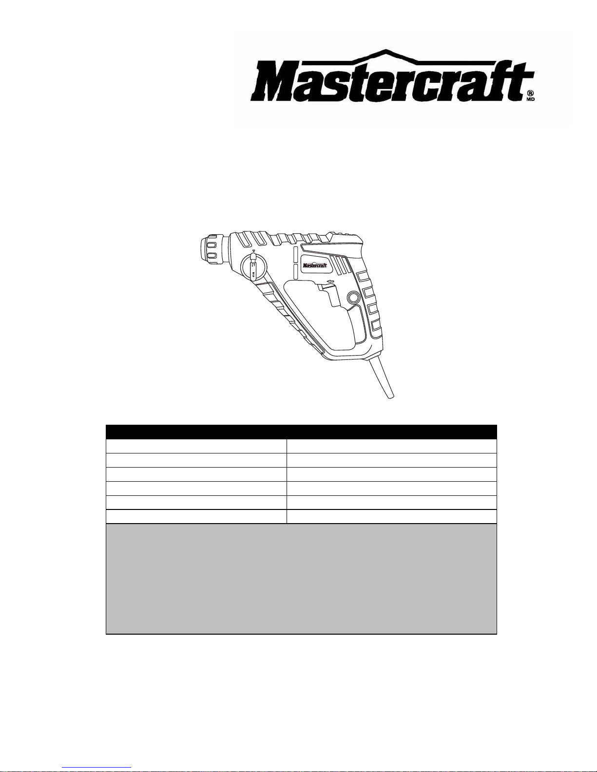
2.8A ROTARY HAMMER
054-1277-8
Owner’s Manual
PRODUCT SPECIFICATIONS
Rating:
120 V, 60 Hz AC
Amperes:
2.5 A
Variable speed:
0–900 RPM (no load)
Beats per minute:
0–4,800 BPM (no load)
Accessory clamping system:
SDS-plus®
Weight:
3 lb. 3 oz. (1.45 kg)
Need Assistance?
Call us on our toll free customer support line:
1-800-689-9928
Technical questions
Replacement parts
Parts missing from package
Imported by Mastercraft Canada Toronto, Canada M4S 2B8
Page 2

2
Product specifications ………….…………………………………………………….
1
Table of contents ……………………………………………………………………...
2
General safety warnings ……………………………………………………………..
3–4
Eye, ear & lung protection ……………………………………………………………
3–4
Electrical safety ……………………………………………………………………….
4
Power tool safety ……………………………………………………………………...
5–7
General safety rules …………………………………………………………………..
5
Work area ………………………………………………………………….…………..
5
Electrical safety ……………………………………………………………………….
5
Personal safety ………………………………………………………………………..
5–6
Power tool use and care of.…………………………………………………………..
6
Service …………………………………………………………………………………
7
Specific safety rules …………………………………………………………………..
7–8
Extension cord safety ………………………………………………………………...
8
Symbols ………………………………………………………………………………..
9
Know your rotary hammer ……………………………………………………………
10
Accessories ……………………………………………………………………………
10
Contents ……………………………………………………………………………….
11
Assembly and operating ……………………………………………………………..
12–19
Forward / reverse switch ……………………………………………………………..
12
Variable speed trigger switch ………………………………………………………..
12
Trigger switch lock-on button ………………………………………………………..
13
Drill / hammer control …………………………………………………………………
13–14
Installing bits & accessories in the SDS-plus® accessory clamping system ……
14–15
Installing a drill bit in the chuck ……………………………………………………...
15–16
Removing drill bits from the chuck ………………………………………………….
16
Drilling ………………………………………………………………………………….
17–19
Maintenance …………………………………………………………………………..
19
Exploded view …………………………………………………………………………
20
Parts list ………………………………………………………………………………..
21–22
Warranty ……………………………………………………………………….………
23–24
TABLE OF CONTENTS
Page 3
3
EYE, EAR & LUNG PROTECTION
This instruction manual includes the following:
General Safety Rules
Specific Safety Rules and Symbols
Functional Description
Assembly
Operation
Maintenance
Accessories
!
ALWAYS WEAR EYE PROTECTION THAT CONFORMS WITH CSA
REQUIREMENTS or ANSI SAFETY STANDARD Z87.1
FLYING DEBRIS can cause permanent eye damage. Prescription
eyeglasses ARE NOT a replacement for proper eye protection.
WARNING: Non-compliant eyewear can cause serious injury if
broken during the operation of a power tool.
SAVE THESE INSTRUCTIONS FOR REFERENCE
WARNING: Use hearing protection, particularly during extended
periods of operation of the tool, or if the operation is noisy.
!
GENERAL SAFETY WARNINGS
WARNING: Before using this tool or any of its accessories, read this
manual and follow all Safety Rules and Operating Instructions. The important
precautions, safeguards and instructions appearing in this manual are not
meant to cover all possible situations. It must be understood that common
sense and caution are factors which cannot be built into the product.
!
Page 4
4
ELECTRICAL SAFETY
WARNING: To avoid electrical hazards, fire hazards or damage to the
tool, use proper circuit protection.
This tool is wired at the factory for 120 V AC operation. It must be
connected to a 120 V AC, 15 A circuit that is protected by a time-delayed
fuse or circuit breaker. To avoid shock or fire, replace power cord
immediately if it is worn, cut or damaged in any way.
GENERAL SAFETY WARNINGS
WEAR A DUST MASK THAT IS DESIGNED TO BE USED WHEN
OPERATING A POWER TOOL IN A DUSTY ENVIRONMENT.
WARNING: Dust that is created by power sanding, sawing, grinding,
drilling, and other construction activities may contain chemicals that are
known to cause cancer, birth defects, or other genetic abnormalities. These
chemicals include:
Lead from lead-based paints
Crystalline silica from bricks, cement, and other masonry products
Arsenic and chromium from chemically treated lumber
The level of risk from exposure to these chemicals varies, according to how
often this type of work is performed. In order to reduce exposure to these
chemicals, work in a well-ventilated area, and use approved safety
equipment, such as a dust mask that is specifically designed to filter out
microscopic particles.
!
Page 5

5
WARNING Read all safety warnings
and instructions. Failure to follow the
warnings and instructions may result in
electric shock, fire and/or serious injury.
Save all warnings and instructions for
future reference.
Work area safety
Keep work area clean and well lit.
Cluttered or dark areas invite accidents.
Do not operate power tools in explosive
atmospheres, such as in the presence
of flammable liquids, gases or dust.
Power tools create sparks which may
ignite the dust or fumes.
Keep children and bystanders away
while operating a power tool.
Distractions can cause you to lose control.
Electrical safety
Power tool plugs must match the outlet.
Never modify the plug in any way. Do
not use any adapter plugs with earthed
(grounded) power tools. Unmodified
plugs and matching outlets will reduce risk
of electric shock.
Avoid body contact with earthed or
grounded surfaces such as pipes,
radiators, ranges and refrigerators.
There is an increased risk of electric shock
if your body is earthed or grounded.
Do not expose power tools to rain or
wet conditions. Water entering a power
tool will increase the risk of electric shock.
Do not abuse the cord. Never use the
cord for carrying, pulling or unplugging
the power tool. Keep cord away from
heat, oil, sharp edges or moving parts.
Damaged or entangled cords increase the
risk of electric shock.
When operating a power tool outdoors,
use an extension cord suitable for
outdoor use. Use of a cord suitable for
outdoor use reduces the risk of electric
shock.
If operating a power tool in a damp
location is unavoidable, use a residual
current device (RCD) protected supply.
Use of a ground fault circuit interrupter
(GFCI) reduces the risk of electric shock.
Personal safety
Stay alert, watch what you are doing
and use common sense when operating
a power tool. Do not use a power tool
while you are tired or under the
influence of drugs, alcohol or
medication. A moment of inattention while
operating power tools may result in serious
personal injury.
Use personal protective equipment.
Always wear eye protection. Protective
equipment such as dust mask, non-skid
safety shoes, hard hat, or hearing
protection used for appropriate conditions
will reduce personal injuries.
Prevent unintentional starting. Ensure
the switch is in the off-position before
connecting to power source and/or
battery pack, picking up or carrying the
tool. Carrying power tools with your finger
on the switch or energising power tools
that have the switch on invites accidents.
Remove any adjusting key or wrench
before turning the power tool on. A
wrench or a key left attached to a rotating
part of the power tool may result in
personal injury.
!
POWER TOOL SAFETY
Page 6

6
PERSONAL SAFETY – cont’d
Do not overreach. Keep proper footing
and balance at all times. This enables
better control of the power tool in
unexpected situations.
Dress properly. Do not wear loose
clothing or jewellery. Keep your hair,
clothing and gloves away from moving
parts. Loose clothes, jewellery or long hair
can be caught in moving parts.
If devices are provided for the
connection of dust extraction and
collection facilities, ensure these are
connected and properly used. Use of
dust collection can reduce dust-related
hazards.
Power tool use and care
Do not force the power tool. Use the
correct power tool for your application.
The correct power tool will do the job
better and safer at the rate for which it was
designed.
Do not use the power tool if the switch
does not turn it on and off. Any power
tool that cannot be controlled with the
switch is dangerous and must be repaired.
Disconnect the plug from the power
source and/or the battery pack from the
power tool before making any
adjustments, changing accessories, or
storing power tools. Such preventive
safety measures reduce the risk of starting
the power tool accidentally.
Store idle power tools out of the reach
of children and do not allow persons
unfamiliar with the power tool or these
instructions to operate the power tool.
Power tools are dangerous in the hands of
untrained users.
Maintain power tools. Check for
misalignment or binding of moving
parts, breakage of parts and any other
condition that may affect the power
tool’s operation. If damaged, have the
power tool repaired before use. Many
accidents are caused by poorly maintained
power tools.
Keep cutting tools sharp and clean.
Properly maintained cutting tools with
sharp cutting edges are less likely to bind
and are easier to control.
Use the power tool, accessories and
tool bits etc. in accordance with these
instructions, taking into account the
working conditions and the work to be
performed. Use of the power tool for
operations different from those intended
could result in a hazardous situation.
Hold power tool by insulated gripping
surfaces, when performing an operation
where the fastener may contact hidden
wiring or its own cord. Fasteners
contacting a "live" wire may make exposed
metal parts of the power tool "live" and
could give the operator an electric shock.
Wear ear protectors. Exposure to noise
can cause hearing loss.
Use auxiliary handle(s), if supplied with
the tool. Loss of control can cause
personal injury.
Hold power tools by insulated gripping
surfaces when performing an operation
where the cutting tool may contact
hidden wiring or its own cord. Cutting
accessory contacting a "live" wire may
make exposed metal parts of the power
tool "live" and could give the operator an
electric shock.
POWER TOOL SAFETY
Page 7

7
Service
Have your power tool serviced by a
qualified repair person using only
identical replacement parts. This will
ensure that the safety of the power tool is
maintained.
WARNING: Know your rotary
hammer. Do not plug the tool into the
power source until you have read and
understand this Instruction Manual.
Learn the tool’s applications and
limitations, as well as the specific
potential hazards related to this tool.
Following this rule will reduce the risk of
electric shock, fire, or serious injury.
Always wear eye protection.
Any power tool can throw
foreign objects into your eyes
and cause permanent eye
damage. ALWAYS wear safety goggles
(not glasses) that comply with ANSI safety
standard Z87.1. Everyday glasses have
only impact resistant lenses. They ARE
NOT safety glasses.
WARNING: Glasses or goggles
not in compliance with ANSI Z87.1
could cause serious injury when they
break.
WARNING: Always use a safety
shield, hearing protection and dust
mask when operating the drill in
"hammer" mode.
Use only hammer drill bits and accessories
that are designed for use with a rotary
hammer when using this rotary hammer in
the hammer mode. Standard drill bits are
NOT designed for use in a rotary hammer
and MUST NOT be used with a rotary
hammer. They may shatter and possibly
cause serious injury.
Do not drill material too small to be
securely held.
Always keep hands out of the path of the
drill bit. Avoid awkward hand positions
where a sudden slip could cause your
hand to move into the path of the drill bit.
Secure the workpiece. Use clamps or a
vice to hold the workpiece. It is safer than
using your hand and it frees both hands to
operate the tool.
Make sure there are no nails or foreign
objects in the part of the workpiece to be
drilled.
To avoid injury from accidental starting,
always remove the plug from the power
source before installing or removing a drill
bit.
Do not install or use any drill bit that
exceeds 7” (17.5 cm) in length or extends
more than 6” (15 cm) beyond the chuck
jaws. They can bend or break suddenly.
SPECIFIC SAFETY
RULES
!
SAVE THESE INSTRUCTIONS FOR REFERENCE
!
POWER TOOL SAFETY
!
Page 8
8
Before starting the operation, jog the drill
switch to make sure the drill bit does not
wobble or vibrate.
Do not use fly cutters or multiple-part hole
cutters, because they can come apart or
become unbalanced during use.
Make sure the spindle has come to a
complete stop before touching the chuck
or attempting to change the drill bit.
When using the chuck, always make sure
the chuck spindle is properly inserted into
the tool and the drill bit firmly tightened in
the chuck before starting the tool.
When using a drill bit or screwdriver bit
adaptor in the tool, make sure it is properly
inserted into the tool before starting the
tool.
WARNING: Keep the extension
cord clear of the working area. Position
the cord so it will not get caught on the
workpiece, tools or any other obstructions
while you are working with the power tool.
Make sure any extension cord used with
this tool is in good condition. When using
an extension cord, be sure to use one of
heavy enough gauge to carry the current
the tool will draw. An undersized cord will
cause a drop in line voltage resulting in
loss of power and overheating.
The table below shows the correct size to
use according to cord length and
nameplate ampere rating. If in doubt, use
the next heavier gauge. The smaller the
gauge number the heavier the cord.
Be sure your extension cord is properly
wired and in good condition. Always
replace a damaged extension cord or have
it repaired by a qualified electrician before
using it. Protect your extension cord from
sharp objects, excessive heat and damp or
wet areas.
Use a separate electrical circuit for your
power tools. This circuit must not be less
than 14 gauge wire and should be
protected with either a 15 AMP time
delayed fuse or circuit breaker. Before
connecting the power tool to the power
source, make sure the switch is in the OFF
position and the power source is the same
as indicated on the nameplate. Running at
lower voltage will damage the motor.
SPECIFIC SAFETY RULES
EXTENSION CORD
SAFETY
!
MINIMUM GAUGE (AWG)
EXTENSION CORDS (120V use only)
Amperage
rating Total length
More
than
Not
more
than
25'
(7.5 m)
50'
(15 m)
100'
(30 m)
150'
(45 m)
0 6 18
16
16
14 6 10
18
16
14
12
10
12
16
16
14
12
12
16
14
12
Not Applicable
SAVE THESE INSTRUCTIONS FOR REFERENCE
Page 9

9
V
Volts
A
Amperes
Hz
Hertz
W
Watts
kW
Kilowatts
Microfarads
L
Litres
kg
Kilograms
H
Hours
N/cm2
Newtons per square
centimetre
Pa
Pascals
Min
Minutes
S
Seconds
Alternating current
Three-phase alternating
current
Three-phase alternating
current with neutral
Direct current
No load speed
Alternating or direct
current
Class II construction
Splash-proof
construction
Watertight construction
Protective grounding at
grounding terminal,
Class I tools
Revolutions or
reciprocations per
minute
Diameter
Off position
Arrow
Warning symbol
Wear your safety
glasses
SYMBOLS
WARNING: Some of the following symbols may appear on the rotary
hammer. Study these symbols and learn their meaning. Proper interpretation
of these symbols will allow for more efficient and safer operation of this tool.
!
This symbol designates that
this tool is listed with both
Canadian and U.S.
requirements by Underwriters
Laboratories.
HOMOLOGUE
61TN
E213739
JD2321U
Page 10

10
AVAILABLE ACCESSORIES
WARNING: Use only accessories
that are recommended for this rotary
drill. Follow the instructions that
accompany the accessories. The use of
improper accessories may result in
injury to the operator or damage to the
tool.
Before using any accessory, carefully read
the instructions or the owner’s manual for
the accessory.
High speed drill bits
Carbide tipped masonry drill bits
Screwdriver bits
WARNING: If any part is missing
or damaged, do not plug the tool into
the power source or install any
accessory until the missing or damaged
part is replaced.
KNOW YOUR ROTARY HAMMER
ACCESSORIES
!
!
SDS-plus® accessory
clamping collar
Variable speed
trigger switch
Air vents
Drill / hammer
control
Lock-on
button
Forward /
reverse switch
Page 11

11
CONTENTS
Carefully unpack the rotary hammer.
Compare the contents against the
"ROTARY HAMMER COMPONENTS"
chart below.
NOTE: See illustration of the rotary
hammer components at right.
WARNING: To avoid fire or toxic
reaction, never use gasoline, naphtha,
acetone, lacquer thinner or similar
highly volatile solvents to clean the
tool.
WARNING: Only use the hammer
function with SDS masonry bits. Never use
the hammer function with high speed steel
(HSS) or wood boring bits.
CONTENTS
!
ROTARY HAMMER COMPONENTS
KEY
DESCRIPTION
QTY
A
Rotary hammer
1
B
SDS-plus® chuck
1
C
SDS-plus® spine
masonry drill bits
6 mm (1/4")
8 mm (5/16")
1
1
D
High-speed steel drill
bits:
1/8" (3.2 mm)
5/32" (4.0 mm)
3/16" (4.8 mm)
1/4" (6.4 mm)
4
E
SDS to 1/4" hex
adapter
1
F
Screwdriver bits
R1, R2
1 ea
(2)
G
Screwdriver bits
PH1, PH2
1 ea
(2)
Tote case
(not illustrated)
1
Owner’s Manual
1
!
Page 12

12
FORWARD / REVERSE SWITCH
The forward / reverse switch (1) is
conveniently mounted above the trigger
switch (Fig. 1). To make the drill rotate
clockwise for drilling or driving screws,
push the forward / reverse switch to the
left. To make the drill rotate counter
clockwise for removing screws, push the
forward / reverse switch to the right.
NOTES:
a) Never change the position of the
forward / reverse switch while chuck is
turning.
b) The trigger switch will NOT function with
the forward / reverse switch in the middle
position.
VARIABLE SPEED TRIGGER SWITCH
This drill is equipped with a variable speed
ON / OFF trigger switch.
1. To start drill, gently squeeze the
trigger switch (2) (Fig. 2).
NOTE: The drill will turn at its slowest
speed when the trigger switch is moved
only a small amount. The drill will turn at its
fastest speed when the trigger switch is
fully depressed.
2. To stop the drill, release the trigger
switch.
NOTE: Drilling at a slow drilling speed for
an extended period of time may cause the
drill motor to overheat. If the drill gets hot,
stop drilling and allow it to cool for at least
15 minutes.
ASSEMBLY AND OPERATING
Fig. 2
Fig. 1
Page 13

13
TRIGGER SWITCH LOCK-ON BUTTON
The trigger switch lock-on feature allows
the trigger switch to be locked in the ON
position at full speed when continuous
operation for extended periods of time is
required (Fig. 3).
1. To lock the trigger switch in the ON
position, pull the trigger switch back
fully to operate the drill at full speed.
2. While holding the trigger fully back,
push the lock-on button (3) into the
drill handle.
3. Release the trigger switch while
holding the lock-on button into the drill
handle. The drill will continue to run.
4. To release the lock-on button, pull the
trigger switch back and then release
the trigger.
DRILL / HAMMER CONTROL
The drill / hammer control (1) changes the
drilling mode between conventional drilling
and hammer for drilling concrete (Fig. 4).
To change from drilling mode to hammer
mode, push the end of the drill / hammer
control knob (2) inward and rotate the knob
180° to the hammer mode. Reverse the
procedure to change from hammer mode
to drilling mode.
NOTE: When the drill / hammer control
knob reaches the desired position, release
the end of the drill / hammer control knob
and move the knob back and forth slightly.
You will hear the knob lock into position.
ASSEMBLY AND OPERATING
Fig. 3
Fig. 4
WARNING: Only use the
hammer function with SDS masonry
bits. Never use the hammer function
with high speed steel (HSS) or wood
boring bits.
!
Page 14

14
DRILL / HAMMER CONTROL – cont’d
WARNINGS:
a) Always use a face shield, hearing
protection and a dust mask when
drilling in concrete.
b) Always use carbide tipped masonry
bits when drilling in masonry. Any other
type of bit could break and possibly
cause serious injury.
INSTALLING BITS & ACCESSORIES IN
THE SDS-PLUS® ACCESSORY
CLAMPING SYSTEM
WARNING: Only use SDS-plus
®
accessories in the SDS-plus® accessory
holder. Using any other accessories may
result in the bits coming loose and possibly
injuring the operator.
To install an SDS-plus® spine carbide drill
bit:
1. Remove the tool plug from the power
source.
2. Slide the accessory clamping collar (1)
toward the rear of the tool (Fig. 5).
3. Insert the shank of the drill bit (2) into
the accessory holder.
NOTE: Make sure the two open keyways
(3) in the drill shank align with the two
matching keys (4) inside the accessory
holder.
4. Push the drill bit shank fully into the
accessory holder and release the
accessory clamping collar so it can
slide forward to lock the drill bit shank
into the accessory holder.
!
ASSEMBLY AND OPERATING
!
Fig. 5
Page 15

15
INSTALLING BITS & ACCESSORIES IN THE
SDS-PLUS® ACCESSORY CLAMPING
SYSTEM – cont’d
5. Carefully pull outward on the drill bit to
ensure it is properly locked into the
accessory holder.
6. To remove the drill bit from the tool,
simply pull back on the accessory
clamping collar and pull the drill bit out
of the tool.
NOTE: Insert and remove the chuck and
screwdriver bit adaptor the same way as
the SDS-plus® spine drill bit above.
INSTALLING A DRILL BIT IN THE
CHUCK
WARNING: Never hold the chuck
body with one hand and use the drill
power to rotate the drill body to loosen
or tighten bits. Serious injury may
result.
This drill is equipped with a double sleeve
keyless chuck.
1. Remove the tool plug from the power
source.
2. To open the keyless drill chuck, grasp
and hold the chuck collar (1) with one
hand (Fig. 6). Rotate the chuck body
(2) with the other hand in a counter
clockwise direction (3) until the chuck
jaws (4) open wide enough to accept
the bit (5).
3. Insert the bit into the chuck the full
length of the jaws. Raise the front of
your drill slightly to prevent the bit from
falling out of the chuck jaws.
ASSEMBLY AND OPERATING
!
Fig. 6
Page 16

16
INSTALLING A DRILL BIT IN THE CHUCK –
cont’d
4. Tighten the chuck jaws onto the bit by
turning the chuck body in a clockwise
direction.
NOTE: Make sure the bit is properly
aligned in the jaws and NOT at an angle.
An improperly aligned bit could be thrown
from the chuck when drill is started. Make
sure flat sides of the screwdriver bit are
being grasped by the chuck jaws.
5. Finish tightening the chuck jaws by
holding the chuck collar with one hand
and firmly tightening the chuck body
by rotating it in a clockwise direction.
NOTE: Hand tighten the chuck jaws. Do
NOT use pliers. You will damage the
chuck.
WARNING: Do not insert the drill
bit into the chuck and tighten as shown
in Fig. 7. The drill bit MUST be properly
inserted with all three of the chuck jaws
holding the bit centered in the chuck.
Failure to properly insert the drill bit
could cause the drill bit to be thrown
from the chuck, resulting in possible
serious injury or damage to the chuck.
REMOVING DRILL BITS FROM THE
CHUCK
1. To open the keyless drill chuck, grasp
and hold the chuck collar with one
hand. Rotate the chuck body with the
other hand in a counter clockwise
direction until the chuck jaws open
and release the bit.
2. Remove the drill bit.
ASSEMBLY AND OPERATING
!
Fig. 7
Page 17

17
DRILLING
When drilling in smooth hard surfaces
such as metal, use a center punch to mark
the desired hole location. This will prevent
the drill bit from slipping off center as the
hole is started.
NOTES:
a) Use slower drilling speeds when drilling
larger holes.
b) Use a masonry bit when operating the
rotary hammer in hammer mode ONLY
when drilling in concrete.
ASSEMBLY AND OPERATING
For safety reasons, the operator must
read the sections of this Owner’s
Manual entitled "GENERAL SAFETY
WARNINGS", "POWER TOOL
SAFETY", "SPECIFIC SAFETY RULES",
"EXTENSION CORD SAFETY" and
"SYMBOLS" before using this rotary
hammer.
Verify the following every time the
rotary hammer is used:
1. Safety glasses, safety goggles, or
face shield is being worn.
2. Hearing protection is being worn.
3. The chuck, drill bit and
accessories are properly installed.
4. The bit is in good condition and is
properly tightened into the SDSplus® clamp or chuck.
Failure to observe these safety rules
will significantly increase the risk of
injury.
WARNING
Page 18

18
DRILLING – cont’d
The workpiece to be drilled should be
secured in a vice or with clamps to keep it
from turning as the drill bit rotates (Fig. 8).
1. Check drill bit to make sure it is firmly
locked into the SDS clamp or drill
chuck and the forward / reverse switch
is in the forward position.
2. Hold the tool firmly with both hands
whenever possible. Use one hand to
grasp the handle and switch and the
other to grasp the body of the tool.
NOTE: Make sure the hand placed on the
body of the tool does not cover the air
vents. Covering these air vents will reduce
the motor cooling and possibly lead to
overheating the motor.
3. While holding the tool firmly, place the
point of the drill bit at the point to be
drilled. Depress the switch trigger to
start the drill.
4. Move the drill bit into the workpiece
applying only enough pressure to
keep the bit cutting. Do not force the
drill bit or apply sideways pressure to
elongate the hole.
WARNING: Be prepared for
binding and bit breakthrough. When
these situations occur, the drill bit has
the tendency to grab the workpiece.
This action will kick the tool opposite to
the direction of drill bit rotation and
could cause loss of control when
breaking through material as you
complete drilling the hole. If you are not
prepared, this loss of control can result
in possible serious injury.
ASSEMBLY AND OPERATING
!
Fig. 8
Page 19

19
DRILLING – cont’d
When drilling metals, use a light oil on the
drill bit to keep it from overheating. The oil
will prolong the life of the drill bit and
improve the drill cutting action. If the bit
jams in the workpiece or if the tool stalls,
release the trigger switch immediately.
Remove the bit from the workpiece and
determine the reason for jamming
DRILLING IN CONCRETE
WARNING: Always use a face
shield when drilling in concrete.
Always use the hammer mode and slower
drill speeds for faster drilling in concrete.
Always use carbide tipped masonry bits.
WARNING: When servicing, use
only identical replacement parts. Use of
any other part may create a hazard or
cause product damage.
DO NOT use solvents when cleaning
plastic parts. Plastics are susceptible to
damage from various types of commercial
solvents and may be damaged by their
use. Use a clean cloth to remove dirt, dust,
oil, grease etc.
WARNING: Do not at any time
allow brake fluids, gasoline, petroleumbased products, penetrating oils, etc. to
come into contact with plastic parts.
They contain chemicals that can
damage, weaken or destroy plastic.
DO NOT abuse power tools. Abusive
practices can damage the tool as well as
the workpiece.
WARNING: DO NOT attempt to
modify tools or create accessories. Any
such alteration or modification is
misuse and could result in a hazardous
condition leading to possible serious
injury. It will also void the warranty.
LUBRICATION
All of the bearings in this tool are
lubricated with a sufficient amount of highgrade lubricant for the life of the unit under
normal conditions. Therefore, no further
lubrication is required.
!
!
MAINTENANCE
ASSEMBLY AND
OPERATION
! ! !
Page 20

20
EXPLODED VIEW
Page 21

21
WARNING: When servicing, use only Mastercraft
®
replacement parts. The use of
any other parts may create a safety hazard or cause damage to the rotary hammer.
Any attempt to repair or replace electrical parts on this rotary hammer may create a safety
hazard unless repairs are performed by a qualified technician. For more information, call
the Toll-free Helpline, at 1-800-689-9928.
Always order by PART NUMBER, not by key number.
Key #
Part #
Part Name
Quantity
1
4030010036
Screw
14
2
3011030001
Housing
1
3
4010010087
Bearing
1
4
1010030011
Rotor assembly
1
5
1230010019
Carbon brush
2
6
3150190119
Insulating ring
1
7
4010010011
Bearing
1
8
1020180002
Stator core
1
9
4010020004
Bearing
1
10
2010010093
Pinion
1
11
4010060004
Bearing
1
12
2040160142
Piston pin
1
13
4010050003
Swing stem bearing
1
14
2050060160
Function spring
1
15
2010060001
Slide cover
1
16
2010060002
Fixed cover
1
17
2030020139
Washer
1
18
2010040070
Shaft 1 19
4010010013
Bearing
1
20
2030020223
Washer
2
21
2020170011
Piston
1
22
4010020031
Bearing
2
23
4010060005
Bearing
1
24
2050060164
Gear wheel snap ring
2
25
2010010094
Gear wheel
1
PARTS LIST
!
Page 22

22
Key #
Part #
Part Name
Quantity
26
4080020001
Steel ball
2
27
2030020227
Washer
1
28
4080090003
Steel ball
1
29
3140020056
Ring 1 30
2040250004
Hammer head
1
31
4100030001
Baffle ring
1
32
2040250007
External ferrule
1
33
3140020058
Ring
2
34
2040250006
Inner ferrule
1
35
2040250005
Impact finger
1
36
3140020060
Ring 1 37
2040240004
Cylinder
1
38
3140020057
Gland strip
1
39
2030020224
Washer
1
40
2050060161
Lock spring
1
41
2040310010
Head cover check plate
1
42
2030020226
Washer
1
43
4100020016
Snap ring
1
44
3150190138
Head cover
1
45
3140080032
Lock rubber
1
46
3120040046
Revolving lock knob
1
47
2050060162
Spring
1
48
1180050044
Function knob
1
49
3140020059
Ring 1 50
4100050002
Snap ring
1
51
3140060002
Shock pad
1
52
1061010007
Switch
1
53
1130090004
PCB 1 54
4030010179
Screw 2 55
2030050002
Cable clips
1
56
3140010050
Cable sheath
1
57
1190030040
Power cable & plug
1
PARTS LIST
Page 23

23
3-Year Limited Warranty
This Mastercraft product is guaranteed for a period of 3 years from the date of
original retail purchase against defects in workmanship and materials, except for the
following components:
a) Component A: Batteries, chargers and carrying cases, which are
guaranteed for a period of 2 years from the date of original retail purchase
against defects in workmanship and materials;
b) Component B: Accessories which are guaranteed for a period of 1 year
from the date of original retail purchase against defects in workmanship
and materials.
Subject to the conditions and limitations described below, this product, if returned to
us with proof of purchase within the stated warranty period and is covered under
this warranty, will be repaired or replaced (with the same model, or one of equal
value or specification),at our option. We will bear the cost of any repair or
replacement and any costs of labour relating thereto.
These warranties are subject to the following conditions and limitations:
a) A bill of sale verifying the purchase and the purchase date must be
provided;
b) This warranty will not apply to any product or part thereof that is worn,
broken or that has become inoperative due to abuse, misuse, accidental
damage, neglect or lack of proper installation, operation or maintenance
(as outlined in the applicable owner’s manual or operating instructions) or
that is being used for industrial, professional, commercial or rental
purposes;
c) This warranty will not apply to normal wear and tear or to expendable parts
or accessories that may be supplied with the product that are expected to
become inoperative or usable after a reasonable period of use;
d) This warranty will not apply to routine maintenance and consumable items
such as, including but not limited to, fuel, lubricants, vacuum bags, blades,
belts, sandpaper, bits, fluids, tune-ups or adjustments;
e) This warranty will not apply where damage is caused by repairs made or
attempted by others (i.e.: persons not authorized by the manufacturer);
f) This warranty will not apply to any product that was sold to the original
purchaser as a reconditioned or refurbished product (unless specified
otherwise in writing);
Page 1 of 2
Page 24

24
3-Year Limited Warranty – cont’d
These warranties are subject to the following conditions and limitations:
g) This warranty will not apply to any product or part thereof if any part
from another manufacturer is installed therein or any repairs or
alterations have been made or attempted by unauthorized persons;
h) This warranty will not apply to normal deterioration of the exterior
finish, such as, including but not limited to, scratches, dents, paint
chips, or to any corrosion or discoloring by heat, abrasive and
chemical cleaners; and
i) This warranty will not apply to component parts sold by and identified
as the product or company, which shall be covered under the product
manufacturer’s warranty, if any.
Additional Limitations
This warranty applies only to the original purchaser, and cannot be transferred.
Neither the retailer not the manufacturer shall be liable for any other expense, loss
or damage, including, without limitation, but not limited to any indirect, incidental,
consequential or exemplary damages arising in connection with the sale, use or
inability to use this product.
Notice to Consumer
This warranty gives you specific legal rights, and you may have other rights, which
may vary from province to province. The provisions contained in this warranty are
not intended to limit, modify, take away from, disclaim or exclude any statutory
warranties set forth in any applicable provincial or federal legislation.
Mastercraft is a superior line of products selected for their workmanship and
materials. These products are designed to meet rigorous quality and performance
standards, and are approved by our Quality Assurance laboratory.
TOLL-FREE HELPLINE: 1-800-689-9928
Page 2 of 2
Rev 1.11 18/06/2011
 Loading...