

Page 1

AC MULTI-CRAFTER
054-1266-4
Owner’s Manual
PRODUCT SPECIFICATIONS
Rating:
120 V, 60 Hz AC
Amperes:
2.3 A
Variable speed:
10,000–18,000 OPM (no load)
Weight:
2 lb 15 oz (1.33 kg)
Need Assistance?
Call us on our toll free customer support line:
1-800-689-9928
Technical questions
Replacement parts
Parts missing from package
Imported by Mastercraft Canada Toronto, Canada M4S 2B8
Page 2

2
Product specifications ………….…………………………………………………….
1
Table of contents ……………………………………………………………………...
2
General safety warnings ……………………………………………………………..
3–4
Eye, ear & lung protection ……………………………………………………………
3–4
Electrical safety ……………………………………………………………………….
4
Power tool safety ……………………………………………………………………...
5–6
General safety rules …………………………………………………………………..
5
Work area ………………………………………………………………….…………..
5
Electrical safety ……………………………………………………………………….
5
Personal safety ………………………………………………………………………..
5–6
Use and care of power tools .………………………………………………………..
6
Service …………………………………………………………………………………
6
Specific safety rules …………………………………………………………………..
7
Symbols ………………………………………………………………………………..
8
Know your multi-crafter ………………………………………………………………
9
Accessories ……………………………………………………………………………
9
Contents ……………………………………………………………………………….
10–11
Assembly and operating ……………………………………………………………..
12–19
Installing accessories …………………………………………………………………
12–13
Installing sandpaper …………………………………………………………………..
13
ON/OFF switch ………………………………………………………………………..
14
Speed control wheel ……………………………………………………………….....
14–15
Flush cutting a door jamb and casing for installing flooring ………………………
16–17
Cutting a hole in wood flooring to install a heating vent …………………………..
17–18
Cutting a hole in drywall for installing an electrical outlet box ……………………
18–20
Using the detail sander attachment …………………………………………………
20
Using the scraper blade ……………………………………………………………...
20–21
Maintenance …………………………………………………………………………..
21
Exploded view …………………………………………………………………………
22
Parts list ………………………………………………………………………………..
23–24
Warranty ……………………………………………………………………….………
25–26
TABLE OF CONTENTS
Page 3
3
EYE, EAR & LUNG PROTECTION
This instruction manual includes the following:
General Safety Rules
Specific Safety Rules and Symbols
Functional Description
Assembly
Operation
Maintenance
Accessories
!
ALWAYS WEAR EYE PROTECTION THAT CONFORMS WITH CSA
REQUIREMENTS or ANSI SAFETY STANDARD Z87.1
FLYING DEBRIS can cause permanent eye damage. Prescription
eyeglasses ARE NOT a replacement for proper eye protection.
WARNING: Non-compliant eyewear can cause serious injury if
broken during the operation of a power tool.
SAVE THESE INSTRUCTIONS FOR REFERENCE
WARNING: Use hearing protection, particularly during extended
periods of operation of the tool, or if the operation is noisy.
!
GENERAL SAFETY WARNINGS
WARNING: Before using this tool or any of its accessories, read this
manual and follow all Safety Rules and Operating Instructions. The important
precautions, safeguards and instructions appearing in this manual are not
meant to cover all possible situations. It must be understood that common
sense and caution are factors which cannot be built into the product.
!
Page 4
4
ELECTRICAL SAFETY
WARNING: To avoid electrical hazards, fire hazards or damage to the
tool, use proper circuit protection.
This tool is wired at the factory for 120 V AC operation. It must be
connected to a 120 V AC, 15 A circuit that is protected by a time-delayed
fuse or circuit breaker. To avoid shock or fire, replace power cord
immediately if it is worn, cut or damaged in any way.
GENERAL SAFETY WARNINGS
WEAR A DUST MASK THAT IS DESIGNED TO BE USED WHEN
OPERATING A POWER TOOL IN A DUSTY ENVIRONMENT.
WARNING: Dust that is created by power sanding, sawing, grinding,
drilling, and other construction activities may contain chemicals that are
known to cause cancer, birth defects, or other genetic abnormalities. These
chemicals include:
Lead from lead-based paints
Crystalline silica from bricks, cement, and other masonry products
Arsenic and chromium from chemically treated lumber
The level of risk from exposure to these chemicals varies, according to how
often this type of work is performed. In order to reduce exposure to these
chemicals, work in a well-ventilated area, and use approved safety
equipment, such as a dust mask that is specifically designed to filter out
microscopic particles.
!
Page 5

5
GENERAL SAFETY RULES
WARNING: Read and understand
all instructions. Failure to follow all
instructions listed below may result in
electric shock, fire and/or serious personal
injury.
WORK AREA
Keep your work area clean and well lit.
Cluttered benches and dark areas invite
accidents.
Do not operate power tools in potentially
explosive environments, such as in the
presence of flammable liquids, gas or dust.
Power tools create sparks that may ignite
dust or fumes.
Keep bystanders, children and visitors
away while operating the tool. Distractions
can cause the operator to lose control.
ELECTRICAL SAFETY
Double insulated tools are equipped with a
polarized plug (one blade is wider than the
other). This plug will only fit into a
polarized plug one way.
If the plug does not fit into the outlet
properly, reverse the plug. If it still does not
fit, contact a qualified electrician to install a
polarized outlet. Do not alter the plug in
any way. Double insulation eliminates the
need for the three-pronged grounded
power cord and grounded power supply
system.
Avoid contact between the operator's body
and grounded surfaces such as pipes,
radiators, ranges, and refrigerators. There
is an increased risk of electric shock if the
operator's body is grounded.
Do not expose power tools to rain or wet
conditions. Water entering the power tool
will increase the risk of electric shock.
Do not abuse the cord. Do not use the
power cord to carry the tool or to pull the
plug out of the outlet. Keep the power cord
away from heat, oil, sharp edges, and
moving parts. Replace a damaged power
cord immediately. A damaged power cord
increases the risk of electric shock.
When operating a power tool outdoors,
use an outdoor-rated extension cord type
“W-A” or “W”. These cords are rated for
outdoor use and they reduce the risk of
electric shock.
PERSONAL SAFETY
Stay alert, be aware of the surroundings,
and use common sense when operating a
power tool. Do not use a power tool while
tired or under the influence of drugs,
alcohol, or medication. A moment of
inattention while operating a power tool
may result in serious personal injury.
Dress properly. Do not wear loose clothing
or jewellery.
Contain long hair. Keep hair, clothing, and
gloves away from moving parts. Loose
clothing, jewellery, or long hair can get
caught in moving parts.
!
POWER TOOL SAFETY
Page 6

6
PERSONAL SAFETY – cont’d
Avoid accidental start-ups. Verify that the
switch is in the OFF position before
plugging in the tool. Carrying a power tool
with a finger on the switch or plugging in a
tool that has the switch in the ON position
invites accidents.
Remove adjusting keys and wrenches
before turning the tool ON. A wrench or
key that is left attached to a rotating part of
the tool may result in personal injury.
Do not overreach. Keep proper footing and
balance at all times. Proper footing and
balance allows the operator to maintain
better control of the tool in unexpected
situations.
Use safety equipment. Always wear eye
protection.
Use a dust mask, non-skid safety shoes, a
hardhat, or hearing protection when
appropriate.
USE AND CARE OF POWER TOOLS
Use clamps or another practical means to
secure and support the workpiece to a
stable platform. Holding the work in a hand
or against the body is not stable, and may
lead to loss of control.
Do not force the tool. Use the correct tool
for the application. The correct tool will do
the job better and safer when used at the
rate that it was designed to work at.
Do not use a power tool if it cannot be
turned ON or OFF using the power switch.
A tool that cannot be controlled using the
switch is dangerous, and must be repaired.
Disconnect the plug from the outlet before
making any adjustments, changing
accessories, or storing the tool. Such
preventive safety measures reduce the risk
of accidental start-ups.
When power tools are not in use, store
them out of the reach of children or
untrained persons. Tools are dangerous in
the hands of untrained users.
Maintain tools with care. Keep cutting tools
sharp and clean. Properly maintained
cutting tools with sharp cutting edges are
less likely to bind, and are easier to
control.
Inspect the tool for misalignment or binding
of moving parts, broken parts, and any
other condition that may affect the
operation of the tool. If it is damaged, have
the tool serviced before using it. Many
accidents are caused by poorly maintained
tools.
Use only accessories that are
recommended by the manufacturer for this
model. Accessories that are suitable for
one tool may become hazardous when
used with another tool.
SERVICE
Tools servicing must be performed by
qualified personnel. Service or
maintenance performed by non-qualified
personnel could result in a risk of injury.
When servicing a tool, use only identical
replacement parts. Follow the instructions
in the Maintenance section of this Manual.
The use of unauthorized parts or failure to
follow the instructions in the Maintenance
section of this Manual may create a risk of
electric shock or injury.
POWER TOOL SAFETY
Page 7

7
WARNING: Know your multi-
crafter. Do not plug the tool into the
power source until you have read and
understand this Instruction Manual.
Learn the tool’s applications and
limitations, as well as the specific
potential hazards related to this tool.
Following this rule will reduce the risk of
electric shock, fire, or serious injury.
Always wear eye protection.
Any power tool can throw
foreign objects into your eyes
and cause permanent eye
damage. ALWAYS wear safety goggles
(not glasses) that comply with ANSI safety
standard Z87.1. Everyday glasses have
only impact resistant lenses. They ARE
NOT safety glasses.
WARNING: Glasses or goggles
not in compliance with ANSI Z87.1
could cause serious injury when they
break.
Always keep hands out of the path of the
saw blade. Avoid awkward hand positions
where a sudden slip could cause your
hand to move into the path of the saw
blade.
Secure workpiece. Use clamps or a vice to
hold the workpiece. It is safer than using
your hand and it frees both hands to
operate the tool.
Make sure there are no nails or foreign
objects in the part of the workpiece to be
cut or sanded.
To avoid injury from accidental starting,
always remove the plug from the power
source before installing or removing an
accessory.
Never use dull blades in the tool. They will
cut slower, leave rough cuts and break
easily due to added pressure and
excessive heat. They will also overload the
motor and cause premature failure of the
tool.
Never use damaged or bent blades. They
will be brittle and break easily possibly
causing injury to the operator.
Never touch a saw blade immediately after
using the tool. The blade will be extremely
hot and will burn your hand.
Only use accessories designed for use
with this tool.
SPECIFIC SAFETY RULES
!
SAVE THESE INSTRUCTIONS FOR REFERENCE
!
Page 8
8
3042597
JD2540U
LISTED
This symbol designates that this tool is
listed with Canadian requirements by
ETL Testing Laboratories, Inc.
Conforms to UL Std. 745-1, 745-2-4.
Certified to CAN/CSA Std. C22.2 No.
745-1, 745-2-4.
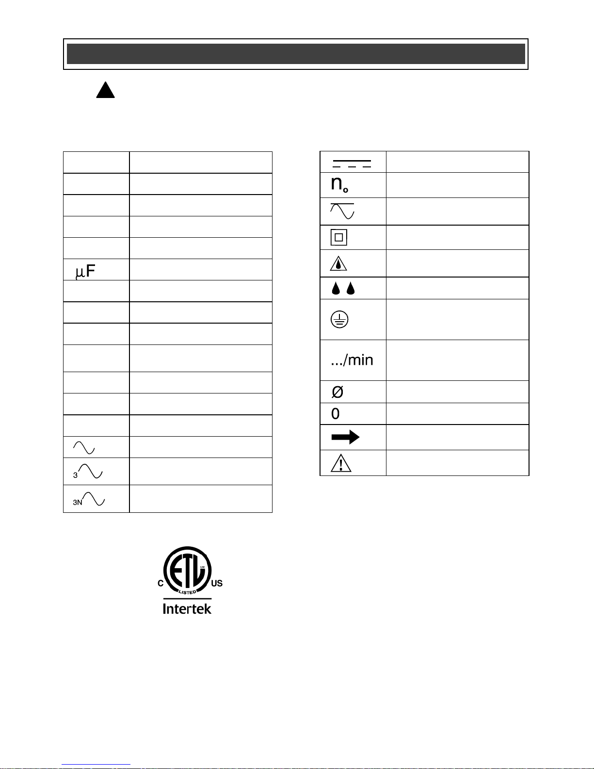
V
Volts
A
Amperes
Hz
Hertz
W
Watts
kW
Kilowatts
Microfarads
L
Litres
kg
Kilograms
H
Hours
N/cm2
Newtons per square
centimetre
Pa
Pascals
Min
Minutes
S
Seconds
Alternating current
Three-phase alternating
current
Three-phase alternating
current with neutral
Direct current
No load speed
Alternating or direct
current
Class II construction
Splash-proof
construction
Watertight construction
Protective grounding at
grounding terminal,
Class I tools
Revolutions or
reciprocations per
minute
Diameter
Off position
Arrow
Warning symbol
SYMBOLS
WARNING: Some of the following symbols may appear on the multi-
crafter. Study these symbols and learn their meaning. Proper interpretation
of these symbols will allow for more efficient and safer operation of this tool.
!
Page 9

9
AVAILABLE ACCESSORIES
WARNING: Use only accessories
that are recommended for this multicrafter. Follow the instructions that
accompany the accessories. The use of
improper accessories may result in
injury to the operator or damage to the
tool.
Before using any accessory, carefully read
the instructions or the owner’s manual for
the accessory.
Saw blades
Scraper blades
Sandpaper
WARNING: If any part is missing or
damaged, do not plug the tool into the
power source or install any accessory until
the missing or damaged part is replaced.
KNOW YOUR MULTI-CRAFTER
ACCESSORIES
!
!
ON/OFF switch
Speed control
wheel
Air vents
Saw blade
Accessory
holder
Hex key
Page 10

10
CONTENTS
Carefully unpack the multi-crafter.
Compare the contents against the “MULTICRAFTER COMPONENTS” chart below.
NOTE: See illustration of the multi-crafter
on Page 11.
WARNING: To avoid fire or toxic
reaction, never use gasoline, naphtha,
acetone, lacquer thinner or similar
highly volatile solvents to clean the
tool.
CONTENTS
MULTI-CRAFTER COMPONENTS
KEY
DESCRIPTION
QTY
A
Multi-crafter
1
B
5 mm Hex key
1
C
Small plunge cutting
saw blade – wood
1
D
Large plunge cutting
saw blade – wood
1
E
Semicircular saw blade
– metal
1
F
Scraper blade
1
G
Sanding pad
1
H
Sandpaper
5
Tote case
(not illustrated)
1
Owner’s Manual
1
!
Page 11

11
CONTENTS
Page 12

12
INSTALLING ACCESSORIES
All accessories are installed on the multicrafter in a similar manner. For the
purposes of describing the accessory
installation, the semicircular blade is used.
DANGER: Always remove the plug
from the power source before installing
or removing accessories or sandpaper.
Failing to remove the plug from the
power source may result in the tool
accidentally being started and causing
serious injury to the operator.
1. Remove the screw (1) and washer (2)
from the accessory holder (3) by
turning the screw counter clockwise.
Use the 5 mm Hex key (4) if the screw
is too tight to be removed by hand
(Fig. 1).
2. Place the blade (5) on the accessory
holder (Fig. 2).
NOTES:
a) Make sure the alignment holes (6) in
the blade fit over the alignment pins
(7) in the accessory holder and the
printed side of the blade is facing the
tool.
b) The blade can be mounted at various
angles left or right of center if
required.
3. Thread the screw (1) through the
washer (2) and the blade and into the
accessory holder threaded hole (8).
4. Turn the screw clockwise until it is
finger tight.
ASSEMBLY AND OPERATING
!
ASSEMBLY AND OPERATING ASSEMBLY AND OPERATING
Fig. 1
4
1
2
3
Fig. 2
Page 13

13
INSTALLING ACCESSORIES – cont’d
NOTES:
a) Check to make sure the convex curve
of the washer (9) is facing the head of
the screw.
b) Make sure the alignment holes in the
blade are still mated with the
alignment pins in the accessory
holder.
5. Firmly tighten the screw with the 5 mm
hex key.
NOTE: Check to make sure the holes in
the blade are still mated with the alignment
pins on the accessory holder after the
screw is fully tightened.
INSTALLING SANDPAPER
1. Install the hook & loop sanding pad (1)
onto the tool (Fig. 3).
2. Firmly press the sandpaper (2) onto
the hook & loop pad.
NOTES:
a) Place the sandpaper so the holes in the
sandpaper line up with the matching holes
in the hook & loop pad.
b) Press the sandpaper firmly onto the
hook & loop pad.
3. To remove the sandpaper, simply peel
the sandpaper way from the hook &
loop pad (Fig. 4).
ASSEMBLY AND OPERATING
Fig. 4
Fig. 3
1
2
Fig. 2
Page 14

14
ON/OFF SWITCH
1. To turn the tool ON, slide the ON/OFF
switch (1) toward the front of the tool
(Fig. 5).
2. To turn the tool OFF, slide the
ON/OFF switch toward the rear of the
tool.
SPEED CONTROL WHEEL
The speed of the tool can be adjusted to
run the tool at speeds varying between
10,000 OPM and 18,000 OPM by rotating
the speed control wheel (1) located toward
the rear of the tool housing (Fig. 6).
1. To increase the speed, rotate the
speed control wheel toward the front
of the tool.
2. To decrease the speed, rotate the
speed control wheel toward the rear of
the tool.
NOTE: Speed #1 is the lowest speed.
“MAX” is the highest speed.
The optimal speed setting will vary
depending upon the type of accessory
being used, the surface being worked and
the complexity of the project. For general
recommendations, see the chart on the
following page.
ASSEMBLY AND OPERATING
Fig. 5
1
Fig. 6
1
Page 15

15
Project
Accessory
Speed
Drywall
Semicircular
blade
Maximum
Restoring
windows
Semicircular
blade
Medium
Door jamb
Wood blade
Maximum
Door casing
Wood blade
Med / max
Wood
dowels
Wood blade
Maximum
Floor vent
Wood blade
Med / max
Copper pipe
Wood blade
Maximum
PVC pipe
Wood blade
Medium
Glued
flooring
Scraper
Medium
Sanding
Sander
Med / max
ASSEMBLY AND OPERATING
For safety reasons, the operator must
read the sections of this Owner’s
Manual entitled “GENERAL SAFETY
WARNINGS”, “POWER TOOL
SAFETY”, “SPECIFIC SAFETY RULES”
and “SYMBOLS” before using this
multi-crafter.
Verify the following every time the
multi-crafter is used:
1. Safety glasses, safety goggles, or
face shield are being worn.
2. Hearing protection is being worn.
3. The blade or sandpaper is in good
condition.
4. The accessory is properly
tightened onto the accessory
holder of the tool.
Failure to observe these safety rules
will significantly increase the risk of
injury.
WARNING
Page 16

16
FLUSH CUTTING A DOOR JAMB AND
CASING FOR INSTALLING FLOORING
The multi-crafter can be used to flush cut a
door jamb and casing to allow space for
the new flooring to fit neatly under the door
jamb and casing. For the purpose of
demonstrating the procedure, floor tile is
being used.
1. Install the plunge cutting wood saw
blade for wood in the tool
(Fig. 2 Page 12).
NOTE: The blade should be centred on
the tool housing and NOT installed in the
90° position.
2. Place a scrap piece of floor tile (1) on
the floor about 1/2" (25 mm) from the
door jamb (2) (Fig. 7).
NOTE: Make sure the “good” side of the
tile is facing upward to provide a smooth
surface for the blade to follow.
3. Place the tool with the saw blade (3)
lightly touching the surface of the tile
and the cutting teeth NOT touching
the surface to be cut.
4. Set the speed to the fastest speed
and turn the tool ON (Fig. 5 & 6 Page
14).
5. When the tool reaches its maximum
set speed, carefully plunge the blade
into the door jamb while sliding the
blade along the floor tile.
NOTE: Hold the tool tightly and do not put
too much forward pressure on the saw
blade when cutting, as this will cause the
tool to vibrate excessively.
ASSEMBLY AND OPERATING
Fig. 7
1
3
4
2
Page 17

17
FLUSH CUTTING A DOOR JAMB AND
CASING FOR INSTALLING FLOORING –
cont’d
6. Continue to make several plunge cuts
until the bottom of the door jamb and
casing are completely cut off and the
loose pieces can be easily removed.
Follow the same basic procedure for
installing carpet, using a thicker spacer
that is the same thickness of the carpet
being installed.
CUTTING A HOLE IN WOOD FLOORING
TO INSTALL A HEATING VENT
The multi-crafter can be used to cut a hole
in wood flooring for installing a heating
vent.
1. Install the plunge cutting saw blade for
wood in the tool (Fig. 2 Page 12).
NOTE: The blade should be centred on
the tool housing and NOT installed in the
90° position.
2. Place the floor vent on the floor and
use a soft lead pencil to trace the
required rectangular hole (1) on the
flooring (Fig. 8).
3. Place the saw blade (2) near the floor
surface in the middle of one of the
cutting lines.
4. Set the tool speed at a medium speed
and turn the tool ON (Fig. 5 & 6 Page
14).
NOTE: The tool and blade should be at a
45° angle to the floor to allow the corner of
the blade to plunge cut into the flooring.
ASSEMBLY AND OPERATING
Fig. 8
1
2
Page 18

18
CUTTING A HOLE IN WOOD FLOORING TO
INSTALL A HEATING VENT – cont’d
5. While holding the tool tightly, slowly
plunge the corner of the blade into the
flooring until it cuts through the
flooring. Once the plunge cut is
complete, set the tool to its highest
speed and complete the cut to the
corner of the rectangle.
6. Turn the saw OFF, remove it from the
cut and proceed to cut in the opposite
direction to complete the cut for the
first side of the rectangle.
7. Repeat steps #4, #5 & #6 to cut the
remaining three sides of the rectangle.
8. When all cuts are complete, use a flat
blade screw driver to carefully pry the
cut-out from the floor.
NOTE: Do NOT use the saw blade to pry
the cut-out from the floor. You will break
the blade. If the cut-out is not easy to pry
from the floor, check to make sure each
line is cut completely into the corner of the
rectangle.
CUTTING A HOLE IN DRYWALL FOR
INSTALLING AN ELECTRICAL OUTLET
BOX
The multi-crafter can be used to cut a hole
in drywall for installing an electrical outlet
box.
1. Install the semicircular saw blade for
wood & drywall in the tool (Fig. 2 Page
12).
ASSEMBLY AND OPERATING
Page 19

19
CUTTING A HOLE IN DRYWALL FOR
INSTALLING AN ELECTRICAL OUTLET BOX –
cont’d
NOTE: The blade should be centred on
the tool housing and NOT installed in the
90° position.
2. Place the outlet box on the drywall
and use a soft lead pencil to trace the
required rectangular hole (1) on the
drywall (Fig. 9).
3. Place the corner edge of the saw
blade (2) near the drywall in the
middle of one of the cutting lines.
4. Set the speed to the highest speed
and turn the tool ON (Fig. 5 & 6 Page
14).
5. When the tool reaches its maximum
speed, carefully plunge the blade into
the drywall until it cuts through the
drywall. Complete the cut to the
corner of the rectangle.
NOTE: Hold the tool tightly and do not put
too much pressure on the saw blade when
cutting.
6. Turn the saw OFF, remove it from the
cut and proceed to cut in the opposite
direction to complete the cut for the
first side of the rectangle.
7. Repeat steps #4, #5 & #6 to cut the
remaining three sides of the rectangle.
8. When all cuts are complete, use a flat
blade screw driver to carefully pry the
cut-out from the drywall.
ASSEMBLY AND OPERATING
Fig. 9
1
2
Page 20

20
CUTTING A HOLE IN DRYWALL FOR
INSTALLING AN ELECTRICAL OUTLET BOX –
cont’d
NOTE: Do NOT use the saw blade to pry
the cut-out from the drywall. You will break
the blade. If the cut-out is not easy to pry
from the drywall, check to make sure each
line is cut completely into the corner of the
rectangle.
USING THE DETAIL SANDER
ATTACHMENT
1. Install the sanding pad on the multicrafter as outlined on Pages 12 & 13,
Fig. 1 & 2.
2. Install the sandpaper on the sanding
pad as outlined on Page 13, Fig. 3 & 4
3. Set the speed control wheel between
4 and MAX as outlined on Page 14,
Fig. 6
4. Turn the switch ON as outlined on
Page 14, Fig. 5
This tool is designed for detail sanding on
small surface areas. Place the sandpaper
surface of the sanding pad on the
workpiece to be sanded. Keep the tool
moving to avoid gouging the surface. Use
coarse sandpaper and lower speeds when
sanding rough surfaces and for removing
previous finishes. Use fine sandpaper and
higher speeds to produce the smoothest
surface.
ASSEMBLY AND OPERATING
Page 21

21
USING THE SCRAPER BLADE
1. Install the scraper blade on the multicrafter as outlined on Pages 12 & 13,
Fig. 1 & 2.
2. Set the speed control wheel to #4 and
turn the switch ON.
When using the scraper blade to scrape
old finishes or glue from a workpiece,
place the under side of the blade flat on
the workpiece surface and then lift upward
on the rear of the tool to allow the blade to
form a very slight angle with the workpiece
surface. Feed the blade slowly into the
material that is to be removed. Do not
force the tool as slower travel speeds will
produce better cutting action and reduce
the risk of gouging the workpiece.
When using the scraper blade to cut
carpet, place a scrap workpiece under the
carpet where the cut is being made. Set
the speed to “MAX”, turn the tool so the
scraper blade is at right angles
(perpendicular) to the carpet and then feed
the blade into the carpet.
GENERAL
WARNING: When servicing, use
only identical replacement parts. The
use of any other part may create a
hazard or cause product damage.
DO NOT use solvents when cleaning
plastic parts. Plastics are susceptible to
damage from various types of commercial
solvents and may be damaged by their
use. Use a clean cloth to remove dirt, dust,
oil, grease etc.
WARNING: Do not allow brake
fluids, gasoline, petroleum-based
products, penetrating oils, etc. to come
into contact with plastic parts. They
contain chemicals that can damage,
weaken or destroy plastic.
DO NOT abuse power tools. Abusive
practices can damage the tool and the
workpiece.
WARNING: DO NOT attempt to
modify tools or create accessories. Any
such alteration or modification is
misuse and could result in a hazardous
condition leading to possible serious
injury. It will also void the warranty.
LUBRICATION
All of the bearings in this tool are
lubricated with a sufficient amount of highgrade lubricant for the life of the unit under
normal conditions. Therefore, no further
lubrication is required.
ASSEMBLY AND
OPERATING
MAINTENANCE
! ! !
Page 22

22
EXPLODED VIEW
Page 23

23
WARNING: When servicing, use only Mastercraft
®
replacement parts. The use of
any other parts may create a safety hazard or cause damage to the multi-crafter.
Any attempt to repair or replace electrical parts on this multi-crafter may create a safety
hazard unless repairs are performed by a qualified technician. For more information, call
the Toll-free Helpline, at 1-800-689-9928.
Always order by PART NUMBER, not by key number.
Key #
Part #
Part Name
Quantity
1
1190030033
Power cord
1
2
6140020006
Hex key
1
3
3140010033
Cord guard
1
4
3150020003
Cord clamp
1
5
4030010099
Screw ST3.9
5
6
1130010123
PCB 1 7
4030010026
Screw ST2.9
3
8
3150160117
Switch cover
1
9
1061150016
Switch
1
10
3111210001
Housing cover – left
1
11
3120110036
Switch lever
1
12
3011210001
Left housing
1
13
1020210002
Stator 1 14
4010010034
Ball bearing 607
1
15
1210160003
Magnetic ring
1
16
3150060017
Brush holder support
2
17
2030070003
Brush holder
2
18
1230010059
Carbon brush assembly
2
19
1010210002
Rotor 1 20
4010010035
Ball bearing 627
2
PARTS LIST
!
Page 24

24
Key #
Part #
Part Name
Quantity
21
2030020134
Washer
1
22
2010130022
Balance block
1
23
4010050002
Ball bearing 625
1
24
4010020005
Needle bearing 0709
1
25
2030200001
Fork 1 26
4010010052
Ball bearing 6001
1
27
2040290035
Spindle
1
28
4030010038
Screw ST2.9X19
2
29
4030010034
Screw ST2.9X16
2
30
3011210001
Right housing
1
31
4030010106
Screw ST3.9
7
32
3111210001
Housing cover - right
1
33
3140060014
Rubber cap
2
34
6070070006
Plunge cut saw blade - I
1
35
2030020177
Blade washer
1
36
4020080032
Screw1\4'' X16
1
37
6070060003
Semi-circular saw blade
1
38
6070070007
Scraping knife
1
39
1150020020
Velcro sanding base plate
1
40
6090030022
Sanding paper
5
41
4100050001
E-ring
1
42
6070070001
Plunge cut saw blade - II
1
PARTS LIST
Page 25

25
3-Year Limited Warranty
This Mastercraft product is guaranteed for a period of 3 years from the date of
original retail purchase against defects in workmanship and materials, except for the
following components:
a) Component A: Batteries, chargers and carrying cases, which are
guaranteed for a period of 2 years from the date of original retail purchase
against defects in workmanship and materials;
b) Component B: Accessories which are guaranteed for a period of 1 year
from the date of original retail purchase against defects in workmanship
and materials.
Subject to the conditions and limitations described below, this product, if returned to
us with proof of purchase within the stated warranty period and is covered under
this warranty, will be repaired or replaced (with the same model, or one of equal
value or specification),at our option. We will bear the cost of any repair or
replacement and any costs of labour relating thereto.
These warranties are subject to the following conditions and limitations:
a) A bill of sale verifying the purchase and the purchase date must be
provided;
b) This warranty will not apply to any product or part thereof that is worn,
broken or that has become inoperative due to abuse, misuse, accidental
damage, neglect or lack of proper installation, operation or maintenance
(as outlined in the applicable owner’s manual or operating instructions) or
that is being used for industrial, professional, commercial or rental
purposes;
c) This warranty will not apply to normal wear and tear or to expendable parts
or accessories that may be supplied with the product that are expected to
become inoperative or usable after a reasonable period of use;
d) This warranty will not apply to routine maintenance and consumable items
such as, including but not limited to, fuel, lubricants, vacuum bags, blades,
belts, sandpaper, bits, fluids, tune-ups or adjustments;
e) This warranty will not apply where damage is caused by repairs made or
attempted by others (i.e.: persons not authorized by the manufacturer);
f) This warranty will not apply to any product that was sold to the original
purchaser as a reconditioned or refurbished product (unless specified
otherwise in writing);
Page 1 of 2
Page 26

26
3-Year Limited Warranty – cont’d
These warranties are subject to the following conditions and limitations:
g) This warranty will not apply to any product or part thereof if any part
from another manufacturer is installed therein or any repairs or
alterations have been made or attempted by unauthorized persons;
h) This warranty will not apply to normal deterioration of the exterior
finish, such as, including but not limited to, scratches, dents, paint
chips, or to any corrosion or discoloring by heat, abrasive and
chemical cleaners; and
i) This warranty will not apply to component parts sold by and identified
as the product or company, which shall be covered under the product
manufacturer’s warranty, if any.
Additional Limitations
This warranty applies only to the original purchaser, and cannot be transferred.
Neither the retailer not the manufacturer shall be liable for any other expense, loss
or damage, including, without limitation, but not limited to any indirect, incidental,
consequential or exemplary damages arising in connection with the sale, use or
inability to use this product.
Notice to Consumer
This warranty gives you specific legal rights, and you may have other rights, which
may vary from province to province. The provisions contained in this warranty are
not intended to limit, modify, take away from, disclaim or exclude any statutory
warranties set forth in any applicable provincial or federal legislation.
Mastercraft is a superior line of products selected for their workmanship and
materials. These products are designed to meet rigorous quality and performance
standards, and are approved by our Quality Assurance laboratory.
TOLL-FREE HELPLINE: 1-800-689-9928
Page 2 of 2
Rev 1.8 14/06/2010
 Loading...