

Page 1
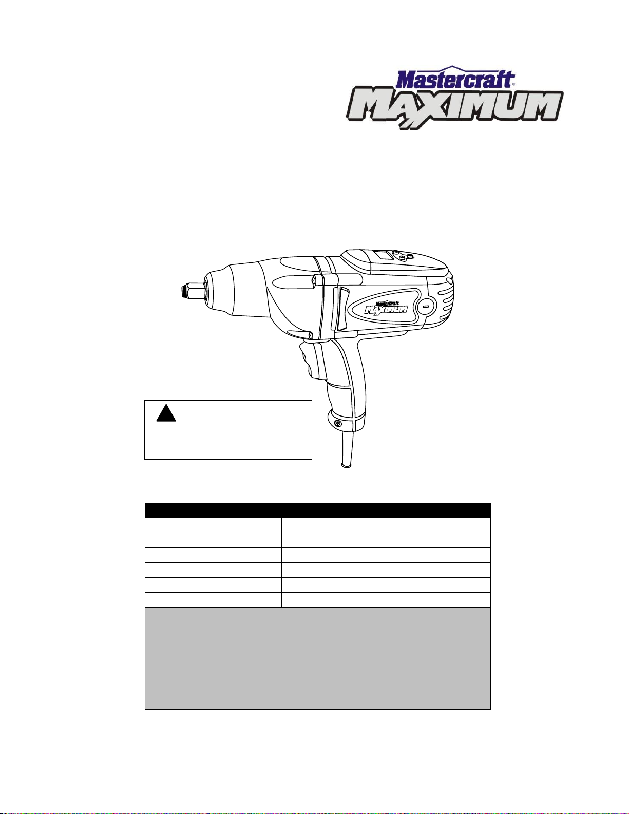
DIGITAL IMPACT WRENCH
054-1265-6
Owner’s Manual
PRODUCT SPECIFICATIONS
Motor:
120 V AC, 60 Hz, 8.5 A
Speed:
2200 RPM (no load)
Impact speed:
3000 BPM (no load)
Torque:
80–350 ft/lbs
Square drive:
1/2”
Weight:
8 lb 13 oz (3.6 kg)
Need Assistance?
Call us on our toll free customer support line:
1-800-689-9928
Technical questions
Replacement parts
Parts missing from package
Imported by Mastercraft Canada Toronto, Canada M4S 2B8
WARNING: Do
not use with modified
sine wave inverter.
!
Page 2

2
Product specifications ………….…………………………………………………….
1
Table of contents ……………………………………………………………………...
2
General safety warnings ……………………………………………………………..
3–4
Eye, ear & lung protection ……………………………………………………………
3–4
Electrical safety ……………………………………………………………………….
4
Power tool safety ……………………………………………………………………...
5–6
General safety rules …………………………………………………………………..
5
Work area ………………………………………………………………….…………..
5
Electrical safety ……………………………………………………………………….
5
Personal safety ………………………………………………………………………..
5–6
Use and care of power tools .………………………………………………………..
6
Service …………………………………………………………………………………
6
Specific safety rules …………………………………………………………………..
7–8
Extension cord safety ………………………………………………………………...
8
Symbols ………………………………………………………………………………..
9
Know your impact wrench ……………………………………………………………
10
Accessories ……………………………………………………………………………
10
Contents ……………………………………………………………………………….
11
Assembly and operation ……………………………………………………………..
12–18
Installing impact sockets ……………………………………………………………..
12
Forward/reverse trigger switch ………………………………………………………
12
Setting the torque value ……………………………………………………………...
13–14
Removing wheel nuts ………………………………………………………………...
15–16
Tightening wheel nuts ………………………………………………………………..
16–18
Maintenance …………………………………………………………………………..
19–20
Exploded view …………………………………………………………………………
21
Parts list ………………………………………………………………………………..
22–23
Warranty ……………………………………………………………………….………
24–25
TABLE OF CONTENTS
Page 3
3
EYE, EAR & LUNG PROTECTION
This instruction manual includes the following:
General Safety Rules
Specific Safety Rules and Symbols
Functional Description
Assembly
Operation
Maintenance
Accessories
!
ALWAYS WEAR EYE PROTECTION THAT CONFORMS WITH CSA
REQUIREMENTS or ANSI SAFETY STANDARD Z87.1
FLYING DEBRIS can cause permanent eye damage. Prescription
eyeglasses ARE NOT a replacement for proper eye protection.
WARNING: Non-compliant eyewear can cause serious injury if
broken during operation of a power tool.
SAVE THESE INSTRUCTIONS FOR REFERENCE
WARNING: Use hearing protection, particularly during extended
periods of operation of the tool, or if the operation is noisy.
!
GENERAL SAFETY WARNINGS
WARNING: Before using this tool or any of its accessories, read this
manual and follow all Safety Rules and Operating Instructions. The important
precautions, safeguards and instructions appearing in this manual are not
meant to cover all possible situations. It must be understood that common
sense and caution are factors which cannot be built into the product.
!
Page 4
4
ELECTRICAL SAFETY
GENERAL SAFETY WARNINGS
WEAR A DUST MASK THAT IS DESIGNED TO BE USED WHEN
OPERATING A POWER TOOL IN A DUSTY ENVIRONMENT.
WARNING: Dust that is created by power sanding, sawing, grinding,
drilling, and other construction activities may contain chemicals that are
known to cause cancer, birth defects. or other genetic abnormalities. These
chemicals include:
Lead from lead-based paints
Crystalline silica from bricks, cement, and other masonry products
Arsenic and chromium from chemically-treated lumber
The level of risk from exposure to these chemicals varies according to how
often this type of work is performed. In order to reduce exposure to these
chemicals, work in a well-ventilated area, and use approved safety
equipment, such as a dust mask that is specifically designed to filter out
microscopic particles.
!
WARNING: To avoid electrical hazards, fire hazards or damage to the
tool, use proper circuit protection.
This tool is wired at the factory for 120 V AC operation. It must be
connected to a 120 V AC, 15 A circuit that is protected by a time-delayed
fuse or circuit breaker. To avoid shock or fire, replace power cord
immediately if it is worn, cut or damaged in any way.
Page 5

5
WARNING Read all safety warnings
and instructions. Failure to follow the
warnings and instructions may result in
electric shock, fire and/or serious injury.
Save all warnings and instructions for
future reference.
Work area safety
Keep work area clean and well lit.
Cluttered or dark areas invite accidents.
Do not operate power tools in explosive
atmospheres, such as in the presence
of flammable liquids, gases or dust.
Power tools create sparks which may
ignite the dust or fumes.
Keep children and bystanders away
while operating a power tool.
Distractions can cause you to lose control.
Electrical safety
Power tool plugs must match the outlet.
Never modify the plug in any way. Do
not use any adapter plugs with earthed
(grounded) power tools. Unmodified
plugs and matching outlets will reduce risk
of electric shock.
Avoid body contact with earthed or
grounded surfaces such as pipes,
radiators, ranges and refrigerators.
There is an increased risk of electric shock
if your body is earthed or grounded.
Do not expose power tools to rain or
wet conditions. Water entering a power
tool will increase the risk of electric shock.
Do not abuse the cord. Never use the
cord for carrying, pulling or unplugging
the power tool. Keep cord away from
heat, oil, sharp edges or moving parts.
Damaged or entangled cords increase the
risk of electric shock.
When operating a power tool outdoors,
use an extension cord suitable for
outdoor use. Use of a cord suitable for
outdoor use reduces the risk of electric
shock.
If operating a power tool in a damp
location is unavoidable, use a residual
current device (RCD) protected supply.
Use of a ground fault circuit interrupter
(GFCI) reduces the risk of electric shock.
Personal safety
Stay alert, watch what you are doing
and use common sense when operating
a power tool. Do not use a power tool
while you are tired or under the
influence of drugs, alcohol or
medication. A moment of inattention while
operating power tools may result in serious
personal injury.
Use personal protective equipment.
Always wear eye protection. Protective
equipment such as dust mask, non-skid
safety shoes, hard hat, or hearing
protection used for appropriate conditions
will reduce personal injuries.
Prevent unintentional starting. Ensure
the switch is in the off-position before
connecting to power source and/or
battery pack, picking up or carrying the
tool. Carrying power tools with your finger
on the switch or energising power tools
that have the switch on invites accidents.
Remove any adjusting key or wrench
before turning the power tool on. A
wrench or a key left attached to a rotating
part of the power tool may result in
personal injury.
POWER TOOL SAFETY
!
Page 6

6
PERSONAL SAFETY – cont’d
Do not overreach. Keep proper footing
and balance at all times. This enables
better control of the power tool in
unexpected situations.
Dress properly. Do not wear loose
clothing or jewellery. Keep your hair,
clothing and gloves away from moving
parts. Loose clothes, jewellery or long hair
can be caught in moving parts.
If devices are provided for the
connection of dust extraction and
collection facilities, ensure these are
connected and properly used. Use of
dust collection can reduce dust-related
hazards.
Power tool use and care
Do not force the power tool. Use the
correct power tool for your application.
The correct power tool will do the job
better and safer at the rate for which it was
designed.
Do not use the power tool if the switch
does not turn it on and off. Any power
tool that cannot be controlled with the
switch is dangerous and must be repaired.
Disconnect the plug from the power
source and/or the battery pack from the
power tool before making any
adjustments, changing accessories, or
storing power tools. Such preventive
safety measures reduce the risk of starting
the power tool accidentally.
Store idle power tools out of the reach
of children and do not allow persons
unfamiliar with the power tool or these
instructions to operate the power tool.
Power tools are dangerous in the hands of
untrained users.
Maintain power tools. Check for
misalignment or binding of moving
parts, breakage of parts and any other
condition that may affect the power
tool’s operation. If damaged, have the
power tool repaired before use. Many
accidents are caused by poorly maintained
power tools.
Keep cutting tools sharp and clean.
Properly maintained cutting tools with
sharp cutting edges are less likely to bind
and are easier to control.
Use the power tool, accessories and
tool bits etc. in accordance with these
instructions, taking into account the
working conditions and the work to be
performed. Use of the power tool for
operations different from those intended
could result in a hazardous situation.
Service
Have your power tool serviced by a
qualified repair person using only
identical replacement parts. This will
ensure that the safety of the power tool is
maintained.
POWER TOOL SAFETY
Page 7
7
WARNING: Know your impact
wrench. Do not plug the tool into the
power source until you have read and
understand this Instruction Manual.
Learn the tool’s applications and
limitations, as well as the specific
potential hazards related to this tool.
Following this rule will reduce the risk of
electric shock, fire or serious injury.
Always wear eye protection.
Any power tool can throw
foreign objects into your eyes
and cause permanent eye
damage. ALWAYS wear safety goggles
(not glasses) that comply with ANSI safety
standard Z87.1. Everyday glasses have
only impact resistant lenses. They ARE
NOT safety glasses.
WARNING: Glasses or goggles
not in compliance with ANSI Z87.1
could cause serious injury when they
break.
Always use hearing protection when
operating the impact wrench.
Use only impact sockets and accessories
that are designed for use with an impact
wrench. Do not use chrome plated sockets
and accessories. Chrome plated sockets
and accessories are designed for hand
use only and MUST NOT be used with an
impact wrench. They may shatter and
possibly cause serious injury.
Before each use, check the impact sockets
and accessories for excessive wear or
cracks. Worn or damaged sockets or
accessories may shatter and possibly
cause serious injury. Worn accessories
may allow the socket to come off during
operation of the impact wrench.
WARNING: Always use a torque
wrench to verify the torque being delivered
each time the impact wrench torque setting
is changed. This will prevent over or under
tightened fasteners.
Keep the impact wrench handle and body
clean and free of oil and grease. Always
use a clean dry cloth when cleaning. Do
not use solvents, brake fluid, gasoline or
other petroleum products to clean the tool.
They will damage the tool.
Do not wear neckties or loose clothing.
When wearing gloves, they must be tight
fitting and slip resistant type. Leather
gloves offer the best protection.
Always use two hands when operating the
impact wrench. Use one hand on the
handle and the other on the front of the
tool body.
Never place your hand so it is touching the
socket or accessory when the tool is
turned ON. Your hand could be seriously
injured.
Always remove the plug from the power
source before installing or removing any
socket or accessory.
Be ready for components to shift when
removing any fastener. The speed of the
fastener removal could cause unexpected
shifting of the components.
Hold the tool by the insulated gripping
surfaces when performing an operation
where the cutting tool may contact hidden
wiring or its own cord. Contact with a “live”
wire will make exposed metal parts “live”
and shock the operator.
SPECIFIC SAFETY RULES
!
!
!
Page 8

8
WARNING: This impact wrench is
calibrated for tightening standard nuts
used on automotive wheel nuts. Using the
torque settings to indicate the torque being
applied to fasteners with finer or coarser
threads will result in the fastener being
either over or under tightened. Always use
a torque wrench to verify the torque being
delivered to the fastener.
WARNING: Only use the pre-set
torque value when tightening right hand
threads. It DOES NOT work when using
the impact wrench to tighten left hand
threaded fasteners.
WARNING: The pre-set torque value
DOES NOT work when using the impact
wrench to remove fasteners. When used in
the REVERSE direction, full torque will be
applied to the fastener.
WARNING: Keep the extension
cord clear of the work area. Position the
cord so that it will not get caught on the
workpiece, a tool, or any other obstruction
while the power tool is in use.
If an extension cord is used with this
impact wrench, verify that it is in good
condition. When using an extension cord,
be sure to use one that is heavy enough to
carry the current that the tool will draw. An
undersized cord will cause a drop in line
voltage, which will result in a loss of power
and overheating.
The following table shows the correct size
to use according to cord length and the
amperage rating that is listed ton the tool's
nameplate. When in doubt, use the next
heavier gauge. The smaller the gauge
number, the heavier the cord.
Verify that the extension cord is properly
wired and in good condition. Replace a
damaged extension cord immediately, or
have it repaired by a qualified electrician
before using it. Keep the extension cord
away from sharp objects, excessive heat,
and damp or wet areas.
Use a separate electrical circuit for power
tools. This circuit must consist of not less
than 14 gauge wire, and should be
protected by either a 15 A time-delayed
fuse or a circuit breaker. Before connecting
the power tool to the outlet, verify that the
switch is in the OFF position, and that the
voltage of the power source is the same as
the voltage that is indicated on the tool's
nameplate. Running this impact wrench at
lower voltage will damage the motor.
EXTENSION CORD
SAFETY
!
MINIMUM GAUGE (AWG)
EXTENSION CORDS (120 V use only)
Amperage
rating Total length
More
than
Not
more
than
25'
(7.5 m)
50'
(15 m)
100'
(30 m)
150'
(45 m)
0 6 18
16
16
14 6 10
18
16
14
12
10
12
16
16
14
12
12
16
14
12
Not Applicable
! ! !
SPECIFIC SAFETY RULES
Page 9

9
This symbol designates that this tool is
listed with Canadian requirements by ETL
Testing Laboratories, Inc.
Conforms to UL Std. 60745-2-2.
Certified to CAN/CSA Std. C22.2 No.
60745-2-2.
3042597
JD2172U
LISTED
V
Volts
A
Amperes
Hz
Hertz
W
Watts
kW
Kilowatts
Microfarads
L
Litres
kg
Kilograms
H
Hours
N/cm2
Newtons per square
centimeter
Pa
Pascals
Min
Minutes
S
Seconds
Alternating current
Three-phase alternating
current
Three-phase alternating
current with neutral
Direct current
No load speed
Alternating or direct
current
Class II construction
Splash-proof
construction
Watertight construction
Protective grounding at
grounding terminal,
Class I tools
Revolutions or
reciprocations per
minute
Diameter
Off position
Arrow
Warning symbol
SYMBOLS
WARNING: Some of the following symbols may appear on the impact
wrench. Study these symbols and learn their meaning. Proper interpretation
of these symbols will allow for more efficient and safer operation of this tool.
!
Page 10

10
AVAILABLE ACCESSORIES
WARNING: Use only accessories
that are recommended for this impact
wrench. Follow the instructions that
accompany the accessories. The use of
improper accessories may result in
injury to the operator or damage to the
impact wrench.
Before using any accessory, carefully read
the instructions or the owner’s manual for
the accessory.
Impact sockets
Impact extensions
Impact adapters
WARNING: If any part is missing or
damaged, do not plug the impact wrench
into the power source until the missing or
damaged part is replaced.
KNOW YOUR IMPACT WRENCH
ACCESSORIES
!
!
½” square
drive
Air vent
Three position
trigger switch
Air vents
Handle
Torque
setting LCD
Torque setting
buttons
LCD display
ON/OFF switch
Motor brush
cap
Socket
retainer
Page 11

11
CONTENTS
Carefully unpack the impact wrench.
Compare against the “COMPONENTS”
chart below.
NOTE: See illustration of contents at right.
WARNING: To avoid fire or toxic
reaction, never use gasoline, naphtha,
acetone, lacquer thinner or similar
highly volatile solvents to clean the
tool.
!
CONTENTS
IMPACT WRENCH
COMPONENTS
KEY
DESCRIPTION
QTY
A
Impact wrench
1
B
Impact sockets
5/8”
3/4"
7/8"
1"
1
1
1
1
Blow moulded case
(Not illustrated)
1
Owner’s manual
1
Page 12

12
INSTALLING IMPACT SOCKETS
WARNING: Use only impact
sockets and accessories that are
designed for use with an impact
wrench. Do not use chrome plated
sockets and accessories. Chrome plated
sockets and accessories are designed for
hand use only and MUST NOT be used
with an impact wrench. They may shatter
and possibly cause serious injury.
WARNING: Always remove the plug
from the power source before changing
any sockets or accessories. You may
injure your hand if the tool is started
accidentally.
To install a socket, press the square
portion of the socket (1) onto the square
drive (2) of the impact wrench (Fig. 1).
NOTE: Slide the socket fully onto the
square drive so the socket retainer (3) will
hold the socket firmly in place.
FORWARD/REVERSE TRIGGER
SWITCH
This impact wrench is equipped with a
rocker style forward/reverse switch (1)
(Fig. 2).
1. To operate the impact wrench in the
forward direction, press and hold the
bottom part of the switch (2). The
socket will rotate in a clockwise
direction to tighten the fastener.
NOTE: This tool includes a soft start
feature to improve control over the tool
during the high torque generated when the
tool starts.
2. To operate the impact wrench in the
reverse direction, press and hold the
top part of the switch (3). The socket
will rotate in a counter clockwise
direction to loosen the fastener.
ASSEMBLY AND OPERATION
!
!
Fig. 2
Fig. 1
Page 13

13
SETTING THE TORQUE VALUE
When tightening fasteners, the preset
torque value in the LCD window will flash
and the digital torque control will
automatically turn the impact wrench OFF
as soon as the preset torque is reached.
NOTE: The digital torque control will
function ONLY when the socket is turning
clockwise to tighten the fastener. When the
socket is turning counter clockwise to
loosen the fastener, maximum torque will
be applied to remove the fastener.
To set the digital torque control:
1. Press the LCD display button (1) once
to turn the LCD display light (2) ON
(Fig. 3). Press the LCD display button
a second time to turn the LCD display
light OFF.
NOTE: The default torque setting of 80
ft/lbs will be visible in the LCD display.
2. Press the “+” button (3) once to
increase the torque setting to 85 ft/lbs
(Fig. 4).
NOTE: Each time the “+” button is
pressed, the torque value will increase by
an additional 5 ft/lbs until the maximum
torque value of 350 ft/lbs is achieved.
3. To reduce the torque value, press the
“–“ button (4). Each time the “–“ button
is pressed, the torque value will
reduce by 5 ft/lbs.
NOTE: Each time the “–“ button is
pressed, the torque value will decrease by
5 ft/lbs until the minimum torque value of
80 ft/lbs is achieved.
ASSEMBLY AND OPERATION
Fig. 3
Fig. 4
Page 14

14
SETTING THE TORQUE VALUE – cont’d
4. To turn the LCD display OFF, press
the torque control button a second
time.
NOTE: The memory within the digital
torque system will “remember” the preset
torque value until the torque value is
changed. When the plug is removed from
the power source, the previous setting will
remain in the memory.
ASSEMBLY AND OPERATION
For safety reasons, the operator
must read the sections of this
Owner’s Manual entitled “GENERAL
SAFETY WARNINGS”, “POWER
TOOL SAFETY”, “SPECIFIC SAFETY
RULES”, “EXTENSION CORD
SAFETY” and “SYMBOLS” before
using this impact wrench.
Verify the following every time the
impact wrench is used:
1. Safety glasses and hearing
protection are being worn.
2. Socket or accessory is “impact
wrench” rated.
3. Socket or accessory is in good
condition.
4. The torque value is set to the
required maximum torque for
the fastener being tightened.
Failure to observe these safety rules
will significantly increase the risk of
injury.
WARNING
!
ASSEMBLY AND OPERATION
Page 15

15
REMOVING WHEEL NUTS
One of the most common uses for the
impact wrench is to remove car wheel nuts
for rotating the tires. Car wheel nut
removal is used for illustrative purposes.
DANGER: Before attempting to
remove a car wheel, make sure all
jacking, wheel blocking and wheel
removal safety procedures illustrated in
the Owner’s Manual for your car are
followed exactly. Failure to follow those
safety instructions could result in
serious injury or death.
1. Install the correct size of impact
socket on the impact wrench as
outlined in Fig. 1.
NOTE: The torque value does not have to
be set for removing fasteners. Maximum
torque will automatically be applied when
operating the impact wrench in the “R” or
counter clockwise direction for removing
fasteners.
2. Plug the impact wrench power cord
into an appropriate power source.
3. Grasp the impact wrench handle (1)
with one hand and the front housing of
the impact wrench (2) with the other
hand (Fig. 5).
4. Place the impact socket (3) onto the
wheel nut.
NOTES:
a) Make sure the socket is fully engaged
with the nut to avoid potentially
damaging the socket or the wheel nut.
b) Maximum torque will be applied to the
socket when the impact wrench is
used in the “reverse” direction
regardless of the torque setting.
!
!
ASSEMBLY AND OPERATION
Fig. 5
Page 16

16
REMOVING WHEEL NUTS – cont’d
5. While holding the tool level with the
ground and with a firm grasp, squeeze
the upper portion of the trigger switch
(4).
NOTE: Once the nut has been removed,
release the trigger. The tool will turn OFF.
When removing fasteners, do not operate
the impact wrench for more than 10
seconds unless the fastener begins to turn.
If the fastener fails to turn within 10
seconds, reverse the direction of rotation
and operate the impact wrench in a
forward direction on the fastener for a few
seconds. Now switch back to reverse
direction and remove the fastener. This
procedure will usually break loose seized
or “frozen” fasteners.
WARNING: Operating the impact
wrench for more than 10 seconds at a time
on a seized or “frozen” fastener will place
severe stress on the impact wrench and
cause damage. It may also break the
fastener.
TIGHTENING WHEEL NUTS
This digital impact wrench can be used to
tighten wheel nuts and other fasteners to a
pre-determined torque by setting the
maximum torque value in the LCD display.
1. Install the correct size of impact
socket on the impact wrench (Fig. 1).
2. Turn the LCD “ON” and set the
maximum torque value to 80 ft/lbs
(Fig. 3 & 4).
!
ASSEMBLY AND OPERATION ASSEMBLY AND OPERATION
Page 17

17
TIGHTENING WHEEL NUTS – cont’d
3. Place the wheel on the wheel studs
and thread one wheel nut (1)
clockwise onto each wheel stud
(Fig. 6).
NOTE: Thread each wheel nut at least
three full turns onto the wheel stud to
make sure the nuts are NOT cross
threaded. The wheel stud and wheel nut
will be damaged if the nut is cross
threaded.
4. Grasp the impact wrench handle with
one hand and the front housing of the
impact wrench with the other hand.
5. Place the impact socket onto the
lower wheel nut (1) (Fig. 7 & 8).
NOTE: Make sure the socket is fully
engaged with the nut to avoid potentially
damaging the socket or the wheel nut.
6. While holding the tool level with the
ground and with a firm grasp, squeeze
the lower portion of the trigger
switch. The impact wrench will tighten
the wheel nut to the set torque of 80
ft/lbs.
NOTE: The LCD display will flash 3 times
and the impact wrench will stop when the
nut is tightened to 80 ft/lbs.
7. Proceed with tightening the remaining
wheel nuts to 80 ft/lbs as noted above.
WARNING: Tighten the wheel nuts
in the sequence outlined in Fig. 7 for 4
stud wheel patterns and Fig. 8 for 5
stud wheel patterns. Following this
sequence is extremely important to
avoid potential distortion of the brake
rotors or drums.
ASSEMBLY AND OPERATION
Fig. 6
Fig. 8
Fig. 7
!
ASSEMBLY AND OPERATION
Page 18

18
TIGHTENING WHEEL NUTS – cont’d
8. Once all the wheel nuts are tightened
to 80 ft/lbs, set the maximum torque
value to that which is recommended
by the vehicle manufacturer or the
fastener manufacturer.
9. Tighten all wheel nuts to the
manufacturer’s recommended torque,
following the same sequence as noted
above.
NOTE: After the tool has been tightening
the nut for approximately 3 seconds, the
pre-set torque will have been reached. At
this point, the tool will turn OFF and the
LCD display will flash 3 times.
10. Once all the wheel nuts are tightened
to the manufacturer’s recommended
torque using the impact wrench, lower
the vehicle so the wheel is firmly in
contact with the ground and verify the
torque of each wheel nut using a
conventional torque wrench.
ASSEMBLY AND OPERATION
Page 19

19
REPLACING CARBON MOTOR
BRUSHES
The carbon motor brushes will wear down
and require replacing. The time intervals
between replacements will vary depending
upon the torques being achieved and the
hours of use. It is recommended that the
brushes be checked after each 10 hours of
use. When the length of the carbon brush
reaches 1/4" (6.35 mm), the brushes
should be replaced.
WARNING: Unplug the tool from the
power source.
1. Use a 3/16" (4 mm) slot screwdriver
and remove one brush cap (1)
(Fig. 9). Turn the brush cap counter
clockwise to remove it from the motor
housing.
2. Pull the spring & brush assembly (2)
from the brush holder (3) in the motor
housing (4).
3. Insert the new spring & brush
assembly into the motor housing.
4. Compress the spring into the brush
holder and thread the brush cap back
into the motor housing.
NOTE: Make sure the brush cap threads
are not cross-threaded. Do NOT over
tighten.
5. Repeat steps 1 to 4 and replace the
second carbon brush located on the
opposite side of the motor housing.
!
MAINTENANCE
Fig. 9
Page 20

20
GENERAL
WARNING: When servicing, use
only identical replacement parts. Use of
any other part may create a hazard or
cause product damage.
DO NOT use solvents when cleaning
plastic parts. Plastics are susceptible to
damage from various types of commercial
solvents and may be damaged by their
use. Use a clean cloth to remove dirt, dust,
oil, grease etc.
WARNING: Do not at any time
allow brake fluids, gasoline, petroleumbased products, penetrating oils, etc. to
come into contact with plastic parts.
They contain chemicals that can
damage, weaken or destroy plastic.
DO NOT abuse power tools. Abusive
practices can damage the tool as well as
the workpiece.
WARNING: DO NOT attempt to
modify tools or create accessories. Any
such alteration or modification is
misuse and could result in a hazardous
condition leading to possible serious
injury. It will also void the warranty.
LUBRICATION
All of the bearings in this tool are
lubricated with a sufficient amount of highgrade lubricant for the life of the unit under
normal conditions. Therefore, no further
lubrication is required.
! ! !
MAINTENANCE
Page 21

21
EXPLODED VIEW
Page 22

22
WARNING: When servicing, use only Mastercraft
®
replacement parts. The use of
any other parts may create a safety hazard or cause damage to the impact wrench.
Any attempt to repair or replace electrical parts on this impact wrench may create a safety
hazard unless repairs are performed by a qualified technician. For more information, call
the Toll-Free Helpline, at 1-800-689-9928.
Always order by PART NUMBER, not by key number.
Key #
Part #
Part Name
Quantity
1
4030010187
Self tapping Screw ST4.9X50
4
2
4040030003
Spring washer φ5
4
3
4040010011
Washer φ5.0
4
4
2020050030
Fixing ring
1
5
3140020017
Washer
1
6
2010080084
Bushing
1
7
2030020196
Washer
1
8
2040040051
Output shaft
1
9
4080080002
Ball φ6.35
2
10
2040200004
Impactor
1
11
4080060001
Ball φ5.0
19
12
2030020197
Washer
1
13
2050060139
Spring 1 14
2040040052
Inner shaft
1
15
2040070002
Gear
1
16
2030020198
Washer
1
17
2010080085
Bushing
1
18
2030020198
Washer
1
19
4081010015
Needle roller
15
20
2040070003
Double gear
1
21
2030020198
Washer
1
22
2040160119
Pin φ8
1
23
2030170009
Airproof washer
1
24
2020130025
Bearing seat
1
25
3190010023
Felt seal
1
26
4010010055
Bearing 6000-2RS
1
PARTS LIST
!
Page 23

23
Key #
Part #
Part Name
Quantity
27
2030110019
Pendulum plate
1
28
3150010071
Fan
1
29
1010180003
Rotor assembly
1
30
4010010060
Bearing 608-2RS
1
31
3140040001
Bearing Sleeve
1
32
2010170017
Magnetism ring
1
33
4100050004
Pendulum plate
1
34
3150050046
Baffle plate - rear
1
35
3150160134
Baffle plate mount
1
36
4030010122
Self tapping screw ST3.9X70
2
37
1020180003
Stator 1 38
2050060140
Electric ring
2
39
3011180003
Housing
1
40
4030010019
Self tapping screw ST2.9X4
1
41
1130040031
Digital PCB
1
42
4030010020
Self tapping screw ST2.9X6
1
43
3160070009
Transparent cover
1
44
3110010137
Decorative plate
1
45
3120020095
Digital button "+"
1
46
3120020096
Digital button "–"
1
47
3120020097
Digital button "I/0"
1
48
1230010066
Brush holder
2
49
3150150019
Carbon brush
2
50
3150140018
Carbon brush cap
2
51
3160010043
Back cover
1
52
4030010105
Self tapping screw ST3.9X20
4
53
1062020029
Switch assembly
1
54
2010170019
Magnetic column
1
55
3120010049
Switch button
1
56
3120070072
Front handle
1
57
4030010106
Self tapping screw ST3.9X20
3
58
1250010002
Terminal block
1
59
4030010099
Self tapping screw ST3.9X14
2
60
2030050002
Cord clamp
1
61
1190040004
Cord 1 62
3140010004
Cord guard
1
PARTS LIST
Page 24

24
5-Year Limited Warranty
This Mastercraft® Maximum® product is guaranteed for a period of five (5) years
from the date of original retail purchase against defects in workmanship and
materials, except for the following components:
a) Component A: Batteries, chargers and carrying cases, which are
guaranteed for a period of two (2) years from the date of original retail
purchase against defects in workmanship and materials;
b) Component B: Accessories which are guaranteed for a period of one (1)
year from the date of original retail purchase against defects in
workmanship and materials.
Subject to the conditions and limitations described below, this product, if returned to
us with proof of purchase within the stated warranty period and if covered under this
warranty, will be repaired or replaced (with the same model, or one of equal value or
specification),at our option. We will bear the cost of any repair or replacement and
any costs of labour relating thereto.
These warranties are subject to the following conditions and limitations:
a) A bill of sale verifying the purchase and purchase date must be provided;
b) This warranty will not apply to any product or part thereof that is worn or
broken or that has become inoperative due to abuse, misuse, accidental
damage, neglect or lack of proper installation, operation or maintenance
(as outlined in the applicable owner’s manual or operating instructions) or
that is being used for industrial, professional, commercial or rental
purposes;
c) This warranty will not apply to normal wear and tear or to expendable parts
or accessories that may be supplied with the product that are expected to
become inoperative or unusable after a reasonable period of use;
d) This warranty will not apply to routine maintenance and consumable items,
including but not limited to fuel, lubricants, vacuum bags, blades, belts,
sandpaper, bits, fluids, tune-ups or adjustments;
e) This warranty will not apply where damage is caused by repairs made or
attempted by others (i.e.: persons not authorized by the manufacturer);
f) This warranty will not apply to any product that was sold to the original
purchaser as a reconditioned or refurbished product (unless otherwise
specified in writing);
Page 1 of 2
Page 25

25
Rev 1.9 13/11/2010
5-Year Limited Warranty – cont’d
These warranties are subject to the following conditions and limitations:
g) This warranty will not apply to any product or part thereof if any part
from another manufacturer is installed therein or any repairs or
alterations have been made or attempted by unauthorized persons;
h) This warranty will not apply to normal deterioration of the exterior
finish including but not limited to scratches, dents, paint chips, or to
any corrosion or discolouring by heat, abrasive and chemical cleaners;
and
i) This warranty will not apply to component parts sold by and identified
as the product of another company, which shall be covered under the
product manufacturer’s warranty, if any.
Additional Limitations
This warranty applies only to the original purchaser, and cannot be transferred.
Neither the retailer nor the manufacturer shall be liable for any other expense, loss
or damage, including but not limited to any indirect, incidental, consequential or
exemplary damages arising in connection with the sale, use or inability to use this
product.
Notice to Consumer
This warranty gives you specific legal rights, and you may have other rights, which
may vary from province to province. The provisions contained in this warranty are
not intended to limit, modify, take away from, disclaim or exclude any statutory
warranties set forth in any applicable provincial or federal legislation.
Mastercraft® is a superior line of products selected for their workmanship and
materials. These products are designed to meet rigorous quality and performance
standards, and are approved by our Quality Assurance laboratory.
TOLL-FREE HELPLINE: 1-800-689-9928
Page 2 of 2
 Loading...